

BEC Integrated Solutions NT-IP-A9K, NT-IP-G9W, NT-IP-G9W-S, NT-IP-DRS1, NT-IP-DRG Installation Manual And Programming Manual
...Page 1
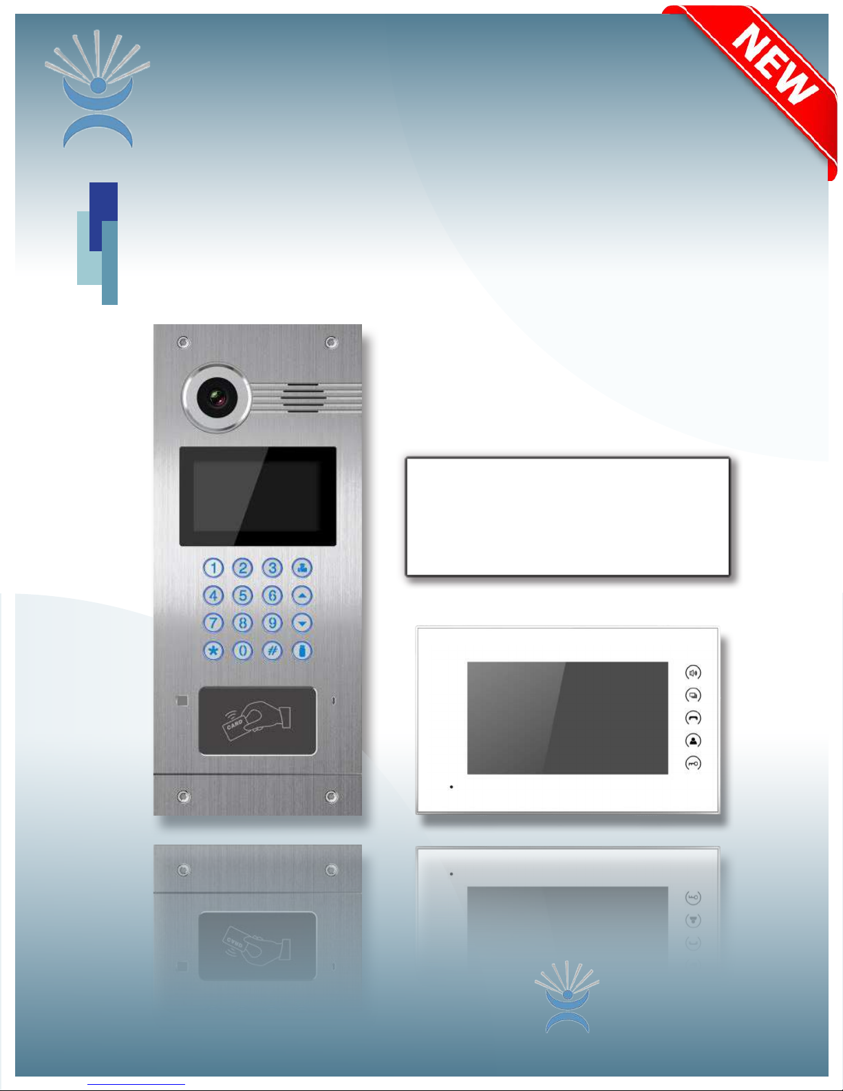
Video Entry System
IP Video Intercom
2017
Installation Manual
and Programming Guide
BEC Integrated Solutions - Williamsville, New York - 716-689-0871
NT-IP-DRS1
BEC
Integrated Solutions
Page 2

IP Video Intercom
Table of Contents
Technical Specications................................................................2
Installation...............................................................................3-7
Conguration & Screenshots
NT-IP-G9W Monitor......................................................10-19
NT-IP-A9K Door Panel...............................................20-24
NT-IP-DRG/DRS1/DRCR....................................24-25
Troubleshooting........................................................................26
Warranty.....................................................................................26
Contact Us.......................................................................................27
5225 Sheridan Drive
Georgetown Square
Williamsville, NY 14221
Phone: 1-716-689-0871
Toll-Free: 1-888-556-3998
E-Mail: support@becsolutionsllc.com
http://www.becintegrated.com
Copyright © 2017 BEC Integrated Solutions LLC.
1
Page 3
Technical Specications
Entry Panels
Outdoor Panel Functions
• Video Intercom with Indoor Monitors and optional management center
• Optional IC/ID/RF card reader
• Passcode Entry
• Supports SIP 2.0 Protocol to communicate with IP phone and SIP software
• Infrared Detection
NT-IP-A9K
• Operating Voltage: 12V DC
• Power: 6W - Operating | 3W - Standby
• Display: 4.3” TFT LCD (480x272)
• IP Rating: IP-54
• Dimensions: 6.1” (W) x 14.76” (H) x 2.05” (D)
• Operating Temperature: 14°F~131°F
(A9K Only)
(A9K & DRCR Only) (max # of fobs = 10,000pcs)
NT-IP-DRG
• Operating Voltage: 12V DC
• Power: 5W (Operating)/2.5W
(Standby) POE Ready
• IP Rating: IP-55
• Dimensions: 3.94” (W) x 6.30”
(H) x 1.85” (D)
• Operating Temperature: -40°F
~ 158°F
NT-IP-DRS1
• Operating Voltage: 12V DC
• Power: 5W (Operating)/2.5W (Stand-
by) POE Ready
• IP Rating: IP-55
• Dimensions: 3.94”(W) x 6.30”(H) x
1.85”(D)
• Operating Temperature: -40°F ~
158°F
NT-IP-DRCR
• Operating Voltage: 12V DC
• Power: 5W (Operating)/2.5W
(Standby) POE Ready
• IP Rating: IP-65
• Dimensions: 4.57”(W) x 7.56”(H)
x 1.85”(D)
• Operating Temperature:
14°F~131°F
2
Page 4

Tech Specs Cont’d
Monitor
NT-IP-G9W-S & NT-IP-G9W
• Operating Voltage: 12V DC (POE)
• Power: 6W (Operating)/2.5W (Standby)
• Screen Size: 7” @ 1024x600 Resolution
• Dimensions: 9.25” (W) x 5.71” (H) x 0.77” (D)
• OS: Android 4.4 KitKat
• Internal Storage: 4GB
• SD Card Maximum: 32GB
Monitor Features
*************
Model NT-IP-G9W-S includes
BEC SIP Server Access
*************
• VOIP: Supports audio/video calling over IP networks, monitoring network door panels & cameras, and
call logging.
• Security: Supports up to 8 alarm zones with 3 states, with built-in zone/scene setup.
• Smart-Home: Can interface with a smart-home system via RS-485 communication.
• Android Features: Ability to install apps via android APK les.
• Built in Micro-USB port for power & data transfer.
Installation
NT-IP-A9K
Punch out
rst for water
drainage
Parts Included:
3
Page 5

Installation Cont’d
A9K Connections & Wiring
Rear
Connections
RS485 Interface
Standard Lock Control Signal
Card Reader Interface
Switching Value Lock Wiring
Door Detection & Exit Switch
Notes:
• The standard control signal can be used with an
Altronix 6062 relay to handle the lock connections
with any lock 9-24vDC or AC.
• The switching value connection supports a max current of 3.5A and requires an external PSU for your
lock. When the outside power is off, the NO and NC
terminals are opposite from normal operation.
• The optional RS485 header enables connections between compatibile equipment. Capable of 12v/100mA
power output.
• Exit/Door Detection header allows for an internal
exit switch and a sensor to know when the door is
open or closed.
• The card reader interface can read keyfobs from a
standalone controller. If unit has reader built-in, it
cannot be used.
4
Page 6

Installation Cont’d
NT-IP-DRG NT-IP-DRS1
Parts Included:
Rear
Connections:
Drain
Back-box
Punch out bottom
hole rst for water
drainage
5
Page 7

Installation Cont’d
NT-IP-DRCR
Screw Holes
Parts Included:
To indoor
building-exit button
Drain
Name Tag
Back-Box
Punch out bottom hole rst
for water drainage
Name Tag
Cover
CNCNO
A Note on Lock Wiring
All IP door panels are designed to operate an electric strike, available as a “slim-style” 12vDC strike plate
from BEC, however any type of lock can be used if wired to the dry contacts on an Altronix 6062 relay, also
available from BEC. You must include an external power source for your lock. If you need assistance
with lock wiring, please contact either BEC technical support, or your lock manufacturer for further support.
6
Page 8

Installation Cont’d
NT-IP-G9W-S & NT-IP-G9W
SD Card
Micro-USB
Port
Camera
(Optional)
Speaker
Talk (Answer)
(Reserved)
Call Guard Station
Monitor
Unlock
Microphone
Connections & Wiring
Home Automation
Security Integration
Alarm
Audio Extension
7
Page 9

General System Diagram
8
Page 10

Features & Set-Up
Quick Overview
Before setting up your system, consider the amount of time it would take you to go room-to-room to program
your monitors. In a large environment with many monitors, it may be extremely time-consuming to
program on-site. In this case, we recommend setting up all monitors locally, one-at-a-time, then installing
them in their assigned rooms. This ensures, not only will the monitors be plug-and-play at that point, but you’ll
have an understanding of the basic system functionality, before your scheduled installation date.
To begin, you’ll need to set the IP address of each monitor and door panel either at each component, or
through a network connected computer using the default IP: 192.168.68.90 for each device, one-at-a-time.
*NOTE*: You’ll have conicting IP addresses out of the box if more than one deviced is connected to the
network.
Once addressed, you’ll need a laptop or computer connected at the switch, or within your network to
access the online settings. To access your online settings out of the box, you’ll need to set the PC’s ethernet
controller’s IPv4 address. Assign the PC’s IP to 192.168.68.xxx (x=# of your choice), with a default gateway
of 192.168.68.1. You can then type in the IP address in a browser window of your choice, enter the admin
credentials (default=admin:123456),then adjust settings using the device’s graphical user interface (GUI).
Note: All door stations, except the full-sized A9K model, must be programmed over the network.
Door Station Main Page
(A9K)
Monitor Network Settings
9
Page 11

NT-IP-G9W-S & NT-IP-G9W
7” Touchscreen Monitor
Features & Set-Up
Main Taskbar: VOIP, Security, Smart, Service, Contact, Calendar, Mediaplayer, and About
Top Shortcuts: Elevator, Out/Secure, Unlock, and Apps
1. Missed and unread notications will appear on the left widget interface.
2. Weather icons and information is synchronized using NTP.
Bottom Navigation Bar: Previous, Home, Multi-Tasking, Volume -, Volume + will appear when outside of the
home screen.
1. Return : Tap to return to the previous screen.
2. Home : Tap to return to the home screen.
3. M u l t i - T a s k i n g : Tap to display currently running apps.
4. Volume- : Tap to decrease volume.
5. Volume+ : Tap to increase volume.
Physical Buttons (Right)
1. Talk (Answer)
2. (Unassigned)
3. Quick Dial Management Center
4. Monitor
5. Unlock
10
Page 12

Features & Set-Up
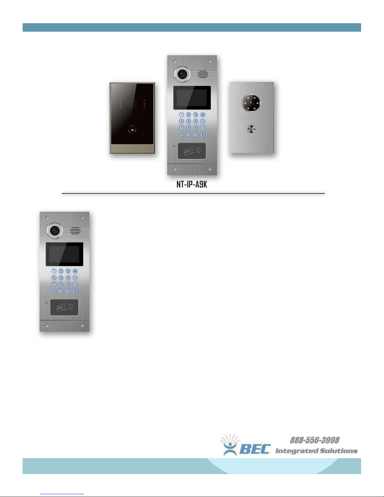
VOIP Menu
Tap VOIP to open the VOIP menu (shown right) -
Call - Tap the call icon to enter the dialing menu.
• To call a network monitor - type the 1-3 digit
building no. + “Building” + 2-digit unit no. +
“Door” + 4-digit room no., then click to call.
(Ex. 1+Building+1+Door+0207 ). The system
will enter into the calling menu, and the called
monitor will ring.
• In the calling menu, press to answer the call,
press to unlock the door, and press to end
the call.
VOIP Menu
Dialing Menu
• While in an active call, press to take a
snapshot, or to start a recording (Photos and
recordings will be saved to external SD card if
installed).
• Tap “center” to call the management center.
Monitor - Tap to open the monitor menu
• Press to begin monitoring the camera feed.
Press or to switch cameras. Press to
end. Press to unlock.
• Press “Door01” to switch from outdoor panel to
at camera modes.
• Monitoring will time-out in 25 seconds.
Calling Menu
11
Page 13

Features & Set-Up
VOIP Menu Cont’d
Monitor Menu
Records Menu
Records - Tap to open the records menu.
• Represents call-dialed
• Represents call-received
• Represents call-missed
• Tap or to scroll through records (Max. 64
records).
• Select one record, press to call; Press to
delete; to back-up. If record has image
attached, press to view it.
Room - Tap room to enter room settings menu
(Default Pass: 123456)
*Note*: Please revise the 6-Digit Sync # ASAP to
prevent conict. The sync # is used to synchronize
multiple devices in one household.
• Building No. - Max 3-Digits (Ex. 001)
• Unit No. - Max 2-Digits (Ex. 01)
• Floor No. - Max 2-Digits (Ex. 03)
• Room No. - Max 2-Digits (Ex. 10)
Room Settings
For this example, when calling from an outdoor panel,
you would dial 0310# (Floor + Unit + #).
• Device No. - Set to 0 for master device, 1-5 will
be set as “slaves” (sub1-sub5).
Additonal devices will need the same SYNC # and
set to device 1 to 5 (including within the IpCalls
smartphone app).
• Server & Password - IP Address of the
Management PC running the available software.
(Default Password: 123456 - set on PC)
12
Page 14

Features & Set-Up
VOIP
For SIP/cell forwarding mobile app setup
instructions, please see the
included with your shipment, or available from
support@becsolutionsllc.com.
BEC will provide SIP Server access for call
forwarding to a mobile app on a North American
based server ONLY on the “G9W-S” monitor.
There is an annual fee associated with the callforwarding service PER DEVICE/SMARTPHONE of
$30 each for up to 3 devices, or $100/year for 4 or
more devices. Please contact BEC or your system
administrator for further information!
Settings
VOIP Menu Cont’d
- Tap VOIP to enter the VOIP Menu.
NT-Setup Guide
VOIP Menu
Intercom Settings
**Internet connection will be required for
cellphone access**
- Tap Settings to open intercom settings.
13
Page 15

Features & Set-Up
VOIP Menu Cont’d
Settings Menu
• Intercom - Camera (Disabled on G9W & G9W-S), Message - ON/OFF, Auto Answer - ON/OFF, Volume
• Network Settings
• DHCP: To automatcially assign an IP address, turn this ON, otherwise adjust the following settings:
• IP Address: Type an IP address to network your monitor to the system. Each IP must be unique.
• Password - Used for system settings (Default = 123456). Can be 1-16 digits.
• QR Code - Used with the IpCalls system application available for smartphones. System settings will be
(Example: 192.168.1.240)
• Mask: Default = 255.255.255.0 - usually, this does not need to be changed.
• Gateway: By denition, the default address of your router - must be the same on all monitors.
(Example: 192.168.1.1)
• DNS: If the indoor monitor is communicating to the internet, this must be set correctly.
(Typical default address would be 8.8.8.8 Google Public DNS)
syncrhonized automatcially, but only available for use on the local network.
Camera - Press camera to enter the IP camera menu.
• Tap to begin monitoring camera. Press to stop.
Select a specic camera using the or keys
• To setup camera access, log into the monitor webpage
via IP address in a web browser.
Use credentials: Username=user; Password=1234
Security Menu
Tap Security on the home screen to enter the
security menu.
ON/OFF - Tap to enter the security mode selection
menu. Tap “Out”, “Home”, or “Sleep” to activate the
alarm system. System sounds 2-beeps and icon
appears at the home screen when active.
• Press “OFF” when system is active to disarm.
(Default Pass = 1234).
14
Page 16

Features & Set-Up
Security Menu Cont’d
Online IP Camera Menu -
• Set max no. of cameras
• Type in a name for the camera.
• Type in the address of your camera in RTSP
format
.
rtsp://user:password@192.168.1.Xx:xxxx/ch01
Zone - Tap Zone to open Zone Menu
• You can adjust the Type, Mode, Delay, and Sensor
mode by tapping on the index within the table
shown below.
Alarm Zone Menu
Online IP Camera Setting
Delay Setting
Type Setting
Sensor Setting
Mode Setting
15
Page 17

Features & Set-Up
Security Menu Cont’d
Scene Menu
Smart Home Menu
Tap Smart to enter into the smart home menu.
Currently, these functions are unsupported by BEC,
but will be in the future. Check with your smart home
device manufacturer. If you have questions, please
call us at 888-556-3998 to speak with a technician!
Scene - Tap scene to enter scene menu (Left).
• Checked options will be active alarms, unchecked
will be inactive within the 3 modes.
• Tap activation time to select between NONE, 30s,
40s, 60s, 100s, or 300s.
Settings - Tap settings to enter the security settings
menu (Below).
• Here you can adjust the security/alarm
password (Default = 1234)
Security Settings
Lighting Menu
Smart Menu
Scene Menu
16
Page 18
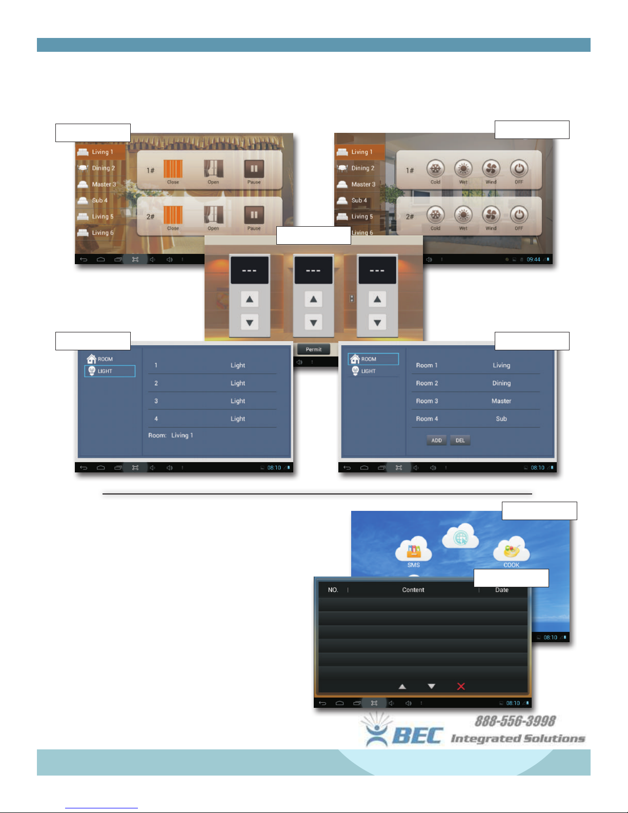
Features & Set-Up
Smart Menu Cont’d
Curtain Menu
Air Menu
Elevator Menu
“Elevator Control” module
required. Check with elevator manufacturer.
Menu SettingsLight Settings
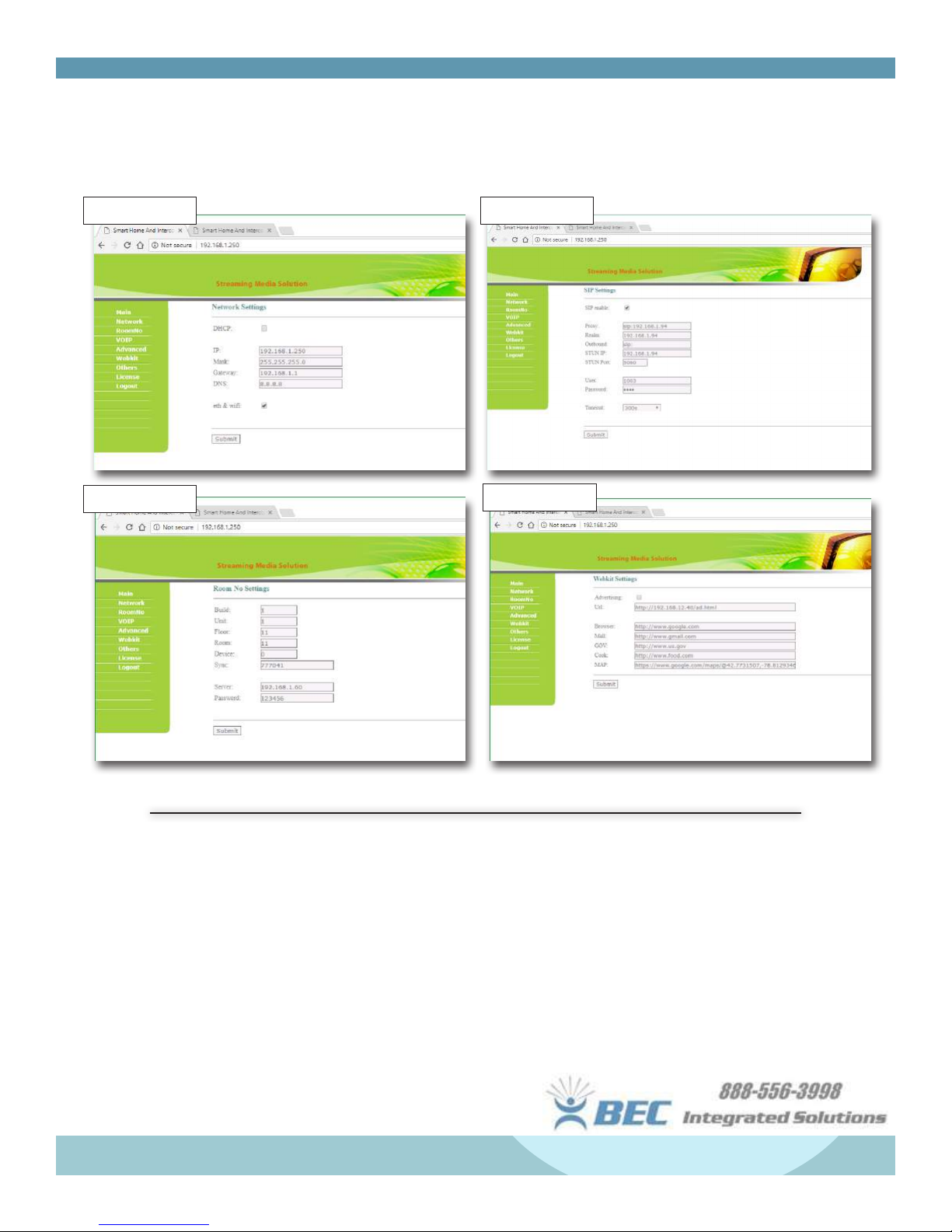
Service Menu
Tap Service to enter the service menu.
These links can be adjusted online via the monitor’s
web-interface from the network computer.
SMS - Can store 64 messages sent from PC using
available management software.
Default links can be set to any online webpage
through the monitor’s online interface.
Service Menu
SMS Records
17
Page 19
Features & Set-Up
Online Settings
Network (1) VOIP (2)
Room No (3)
Webkit (4)
Online Settings - Accessed @ IP Address of monitor (Note: .
1. IP Address/DHCP/Gateway/DNS Addresses can be addressed here. See pg 14. for further info.
2. SIP Addresses can be entered here as well as the monitor. See pg 13. for further info.
3. Room Number, Floor Number, etc. can all be adjusted here. See pg. 12 for further info.
4. Webkit allows you to address the links within the service menu to Gov, Cook, Mail, Map, and
Browser.
18
Page 20
Features & Set-Up
Online Settings Cont’d
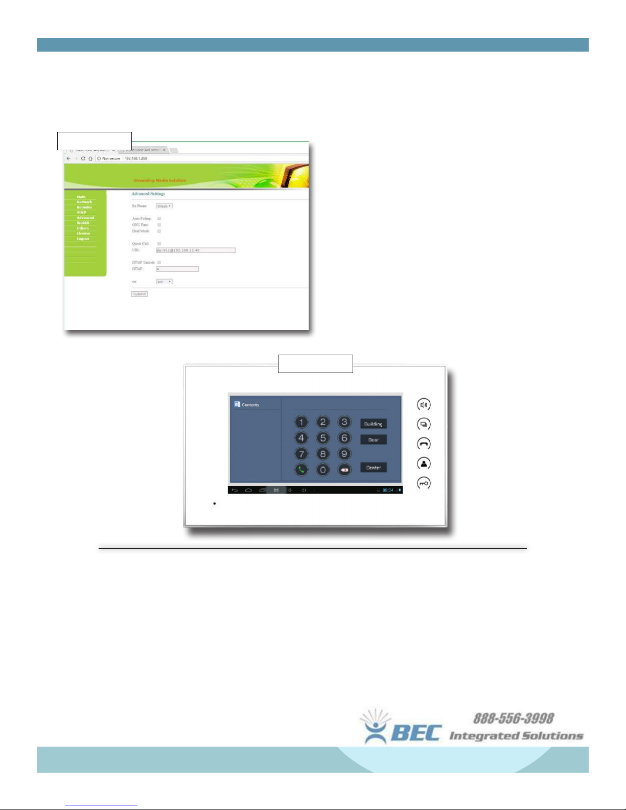
Advanced (5)
Online Settings - Accessed @ IP Address of monitor.
5. Advanced Settings -
• ExPhone: Input IP Address of other SIP/VOIP
device as the sub deivce of indoor monitor. When
outdoor panel calls indoor monitor, IP device will
ring at the same time.
• Auto Pickup: Checked, the indoor monitor will
answer after unanswered 10s.
• Quick Call: You can address a device to ring
when the “Center” button is pressed under the
Calling menu.
Calling Menu
Additonal Notes
• The micro-usb port on the side can be used to connect to computer’s usb-port to transfer media
les or Android application les (.apk).
• You can access the
Android
right corner. Navigate to settings to adjust additional settings such as date & time, system info, and to
turn on “Install from Unknown Sources”. This is required to install additional apps such as the Android
Play Store, if desired.
• Monitor footage/photos can be removed via MicroSD or micro-USB cable.
system app drawer via the main screen, and tapping apps in the upper
19
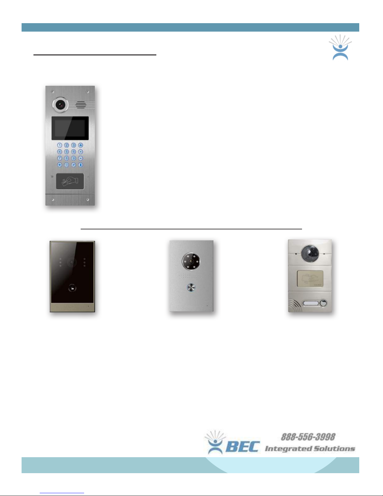
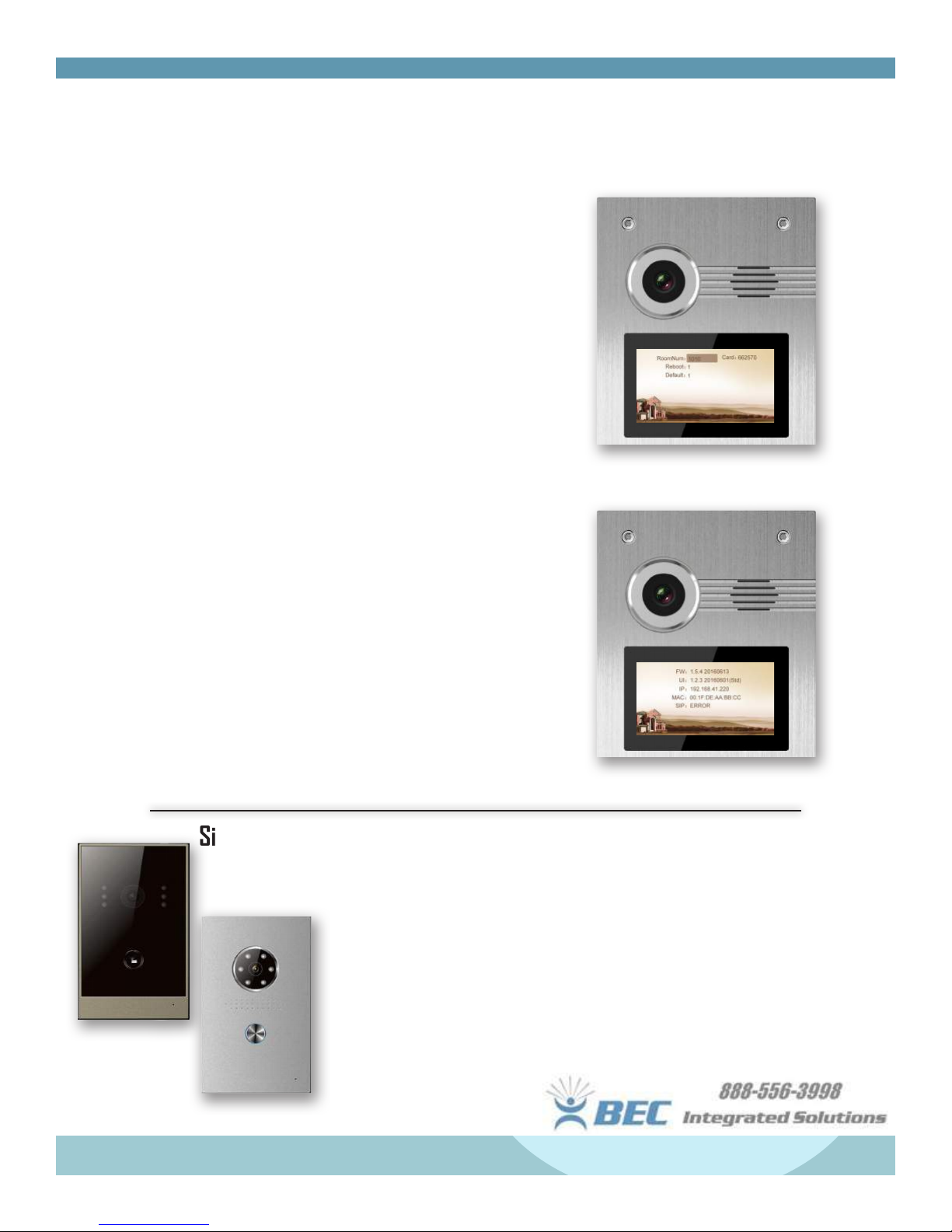
Page 21
Features & Set-Up
Door Station Settings
NT-IP-DRG
NT-IP-A9K
NT-IP-DRS1
NT-IP-A9K Set-Up
Basic Operation
• When programmed as an “outdoor panel”, type at least 3 digits (oor + room) to
call a room.
• When programmed as a “wall station”, type the building no. + #, unit no. + #, +
Room no. + # (at least 7 digits).
• If room exists, monitor will dial and room monitor will ring. If device not found, a
failure tone and message will appear. If indoor monitor is busy, “Busy” will appear.
• During communication, “*” will end the call.
(Example: 0312#)
Unlocking the Door
• Press # then type the access password (Default = 0000). Press # to conrm. If
password is correct, door will unlock. If incorrect, an error will sound.
• To unlock via IC/ID card, swipe or place the fob on the card reader area of the
panel. If registered, the door will unlock.
20
Page 22
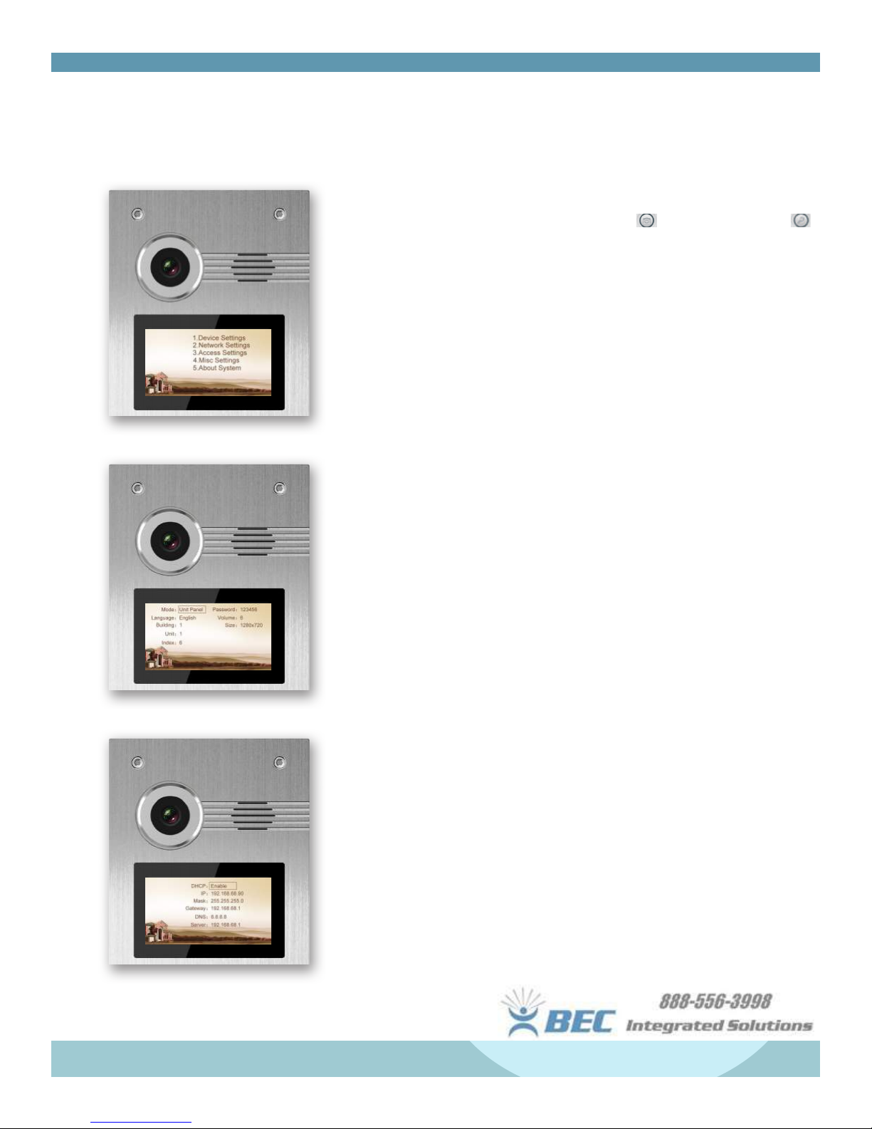
Features & Set-Up
A9K Door Setup
Panel Settings - Press ‘#’ TWICE to bring up the admin prompt then type the
admin password (Default = 123456)
• To navigate through the menu, press 2 or to go UP, press 8 or
to go down. Press ‘#’ to conrm; press ‘*’ to return.
1. Device Settings
• Device Mode: Choose between “Unit Panel” or “Wall Panel” -
Unit panels can call monitors within only that unit, while wall
panels can call any monitor within your network.
• Language Settings
• Volume: Set volume from 1-6, 6 being the loudest.
• Size: Screen resolution, choose between 230x240, 640x480,
or 1280x720
• Password: Admin password for device settings.
(Default = 123456)
2. Network Settings
• DHCP: Enable/Disable
• IP Address: Set for network access. Must be unique.
• Mask: Default Mask = 255.255.255.0
• Default Gateway: Default is 192.168.68.1
• DNS: Default = 8.8.8.8
• Server: Refers to the network PC running the management
software. Default = 192.168.68.1
3. Access Settings
• Timeout: Controls how long the unlock will hold for. Set from
1-9 seconds. Ineffective if using an Altronix 6062 relay.
• Delay: Controls a delay between user pressing the unlock key
on a monitor and opening at the door. Set from 1-9 seconds.
• Password: Sets the unlock code for passcode access to the
building. (6 digits)
4. Misc Settings
• The “RoomNum” setting is to assign a keycard to a room #.
• Reboot: Set to 1 to reboot the panel.
• Default: Set to 1 to set to system defaults.
21
Page 23
Features & Set-Up
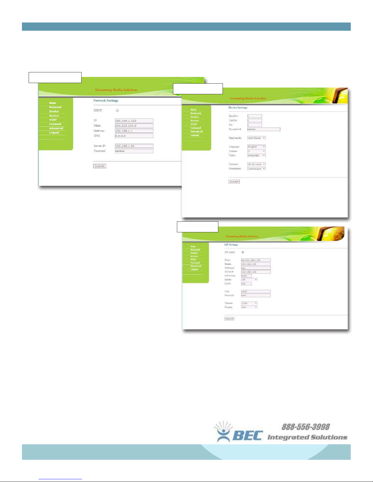
A9K Door Setup Cont’d
1. Network Settings
Online Settings - Accessed through assigned IP
address on a network based computer.
2. Device Settings
1. Network Settings
• DHCP: Enable/Disable
• IP Address: Default = 192.168.68.90
• Default Mask: 255.255.255.0
• Gateway: Default = 192.168.68.1
• DNS Address: 8.8.8.8
• Server IP: Address of the management PC
• Password: For PC access (default = 123456)
2. Device Settings
• Build and Unit Number need to be the same of
the Outdoor Panel.
• Unique for the Outdoor Panel. Max of 9 outdoor
panels.
• Sys Password: Default = 123456; this changes
the login password for online access, and panel
admin settings outside.
• Panel Mode:
• Unit panel - Used in one unit; calls residents and
guard station. (This is the most common mode).
3. SIP Settings
• Panel Mode Cont’d
• Wall panel - Used at a community entrance; calls
outdoor panels, residents, and management center.
• Personal Panel - N/A
• Panel volume and language can be adjusted as well.
• Forward: Change between “All at Once” or “One by
One” to change the call fowarding behavior.
22
Page 24
Features & Set-Up
A9K Door Setup Cont’d
Online Settings - Available via assigned IP Address of the door station.
3. SIP Settings
• User & Password: Assigned by the SIP server.
• Screen Timeout: 2m, 5m, 10m, 20m, or 30m.
• Ringing: Time in seconds the user will have to answer the call at the monitor.
Further SIP/Call Forwarding information can be found on the NT-Setup Guide document included in your
shipment, or available via email by contacting support@becsolutionsllc.com.
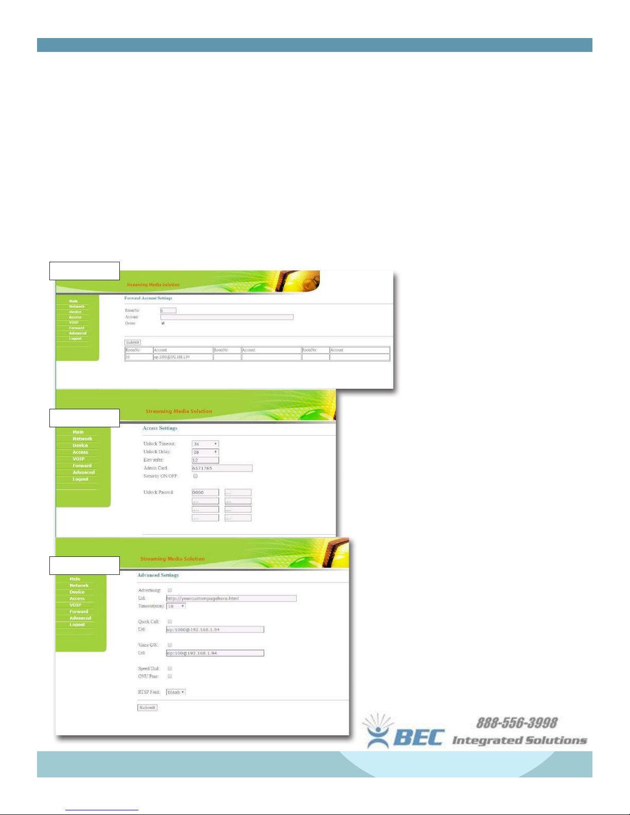
4. Call Forward
5. Access
6. Advanced
4. Foward
• Room No.: Calling-code to assign
forwarding rule to
• Account: SIP/VOIP IP Address
to foward a missed call to. Calls
will forward to cell phone app if
successfully authenticated
5. Access Settings
• Unlock Timeout - controls time lock is open
(1-9s)
N/A if 6062 Relay is used.
• Unlock Delay - delay from monitor to door
(1-9s)
• Elev Refer is used for setting the oor # from
01-99 for your elevator control module.
• Security On/Off: Arming is only at a secondary
panel, unit panel only supports disarming by
card.
• Unlock Password: Used for unlocking by
passcode at the door keypad. Default =
000000. 8 different passwords can be
created.
23
Page 25
Features & Set-Up
A9K Door Setup Cont’d
Online Settings - Accessed @ IP Address of door
station.
6. Advanced Settings
• Advertising: Check the box to have the panel
automatcially display the webpage input into the
URL eld.
• Quick Call: Check the box to enable to assign
monitor’s “Center” button in calling menu to call
web address typed into the URL eld.
• Speed Dial: Press one # key to give a direct call.
Additional A9K Notes
• “SIP: OK” will show on the online homepage when
SIP account is successfully authenticated.
• The BE-KF keyfobs/ID cards can be entered into
the system online using the last 7 digits printed
on the fob. The admin card is required to program
fobs.
• To program fobs, swipe the admin card once,
swipe all fobs to be programmed, then swipe
admin card once more.
Single-Button Door Setup
Operation
NT-IP-DRG
NT-IP-DRS1
• Calling: In standby mode, call
button will call corresponding
indoor monitor. Can also be set
up as a help station, which will
call the management station.
• Online Settings Menu: Connect
to door panel with door panel’s
default IP address: 192.168.68.90
(Login with: admin ; 123456)
24
Page 26

Features & Set-Up
Single-Button Door Setup Cont’d
(NT-IP-DRS1 & NT-IP-DRG)
1. LAN Setting
• IP Address: Must be unique in the LAN
(Default IP = 192.168.68.90)
• Mask: Default mask = 255.255.255.0
• Gateway: Dependant on the IP address
(Default Gateway = 192.168.68.1)
• DNS: Typically 8.8.8.8
• Server IP: Assigned IP Address of management
PC running the corresponding software.
• NTP: Network Time Protocol -
2. Device Setting
3. Access Setting
4. VOIP Setting
(Default = ntp.nasa.gov)
• The building and unit no. should be the same of
corresponding indoor monitor.
• No.: Outdoor panel no. (1-9) Maximum 9
outdoor panels.
• System password: Change the online login
password (Default = 123456)
• Panel mode: Choose between wall panel or
personal panel.
• Ring back: Choose the tone to playback at
panel.
• Unlock timeout: Set the door open for 1-9s.
• Unlock delay: Set the delay from monitor to
door for 0-9s.
• Unlock Password, Elev Refer, Admin Card are
disabled (N/A)
• Input Relevant SIP Server Information
(See A9K page for default addresses and eld
descriptions)
5. Forward (Call Transfer)
• Call Indoor Monitor: Monitor can be assigned
an IP address to call if there is no answer
within 25 seconds. Input room No. of indoor
monitor then input sip account address.
(Example: sip:1000@yoursip.domain.com)
One-Button Reader Setup (NT-IP-DRCR)
Press call button to call assigned
monitor.
Swipe programmed ID Card at panel
to unlock door.
To access the online settings menu,
type in the IP address in a browser
NT-IP-DRCR
All programming functions are the same as other
single-button panels, with the exception of the access
settings to allow for card reader programming. Within
the online menu, type in last 8-digits on the ID card/
fobs under admin to assign your admin card. If admin
card # is unknown, type 0, hit “submit”, then swipe
your desired admin card.
To program fobs, swipe the admin card at the reader,
swipe fobs to program, then swipe the admin card
once more.
window on a network-connected PC.
(Default IP = 192.168.68.90)
25
Page 27

Management Software
Please see additional management software manual for further assistance with software setup.
Troubleshooting & Other Info.
For assistance with BEC Server Connectivity, please refer to the NT-Setup Guide, or contact us at 888-556-3998
for further setup help.
All systems will be shipped with an Altronix 6062 relay for unlocking. This relay is compatible with all types
of locking mechanisms, so long as a compatible power supply is provided for power. Please contact technical
support for custom locking diagrams if you have an alternative lock.
There is a 1 year limited warranty available on each component beginning at the time of purchase. Please contact
technical support at ext. 4 for troubleshooting assistance. We will issue an RMA and replace the unit if found
defective after troubleshooting.
We hope you enjoy your new IP based video entry system! We
are excited to introduce this to our current lineup of available
intercom systems and believe this system will withstand the
ever changing market of entry-technology.
If you have any questions, or would like to speak about any
issues you come across during your usage, or are interested
in additional systems for your future projects, please call us
at our main line, or email support@becsolutionsllc.com and
we will do our best to meet your needs!
26
Page 28

BEC
Integrated Solutions
Georgetown Square
5225 Sheridan Drive
Williamsville, NY, 14221
Phone: 716-689-0871
Email: support@becsolutionsllc.com
http://www.becintegrated.com
Rev. 9/19/17
Copyright © 2017
BEC Integrated Solutions LLC.
27
 Loading...