

Page 1
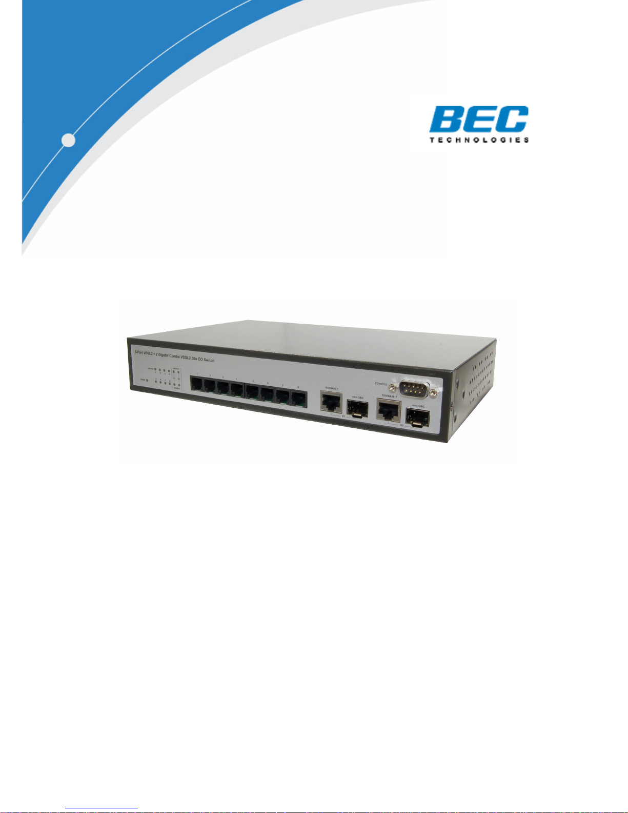
8-Port VDSL2 + 2 Gigabit Combo
VDSL2 30a CO Switch
BEC V8E2G
User Manual
-1-
Page 2

The information in this guide may be changed without notice. The
manufacturer assumes no responsibility for any errors which may appear in
this guide.
Ethernet is a trademark of XEROX Corporation. Microsoft, Windows and
Windows logo are trademarks of Microsoft Corporation.
Copyright 2010.All rights were reserved. No Part of the contents of this guide
maybe transmitted or reproduced in any form or by any means without the
written permission of BEC Technologies, Inc..
The revision date for this guide is Jan. 2010,
Version 1.0I
FCC Statement
This product has been tested and found to comply with the limits for a Class A
digital device pursuant to Part 15 of FCC Rules. These limits are designed to
provide reasonable protection against such interference when operating in a
commercial environment. This equipment generates uses and can radiate
radio frequency energy, and if not installed and used according to the
instructions, may cause harmful interference to radio communications.
Operation of this equipment in a residential area is likely to cause interference,
in which the case user, at his or her own expense will be required to take
whatever measures to correct the interference.
CE Mark Warning
This is a Class A product. In a domestic environment, this product may cause
radio interference in which case the user may be required to take adequate
measures.
-2-
Page 3

Contents
1. Introduction................................................................................................ 4
1.1. Package Contents............................................................................4
1.2. How to Use this Guide ..................................................................... 4
2. Installation..................................................................................................5
2.1. Product Description Overview..........................................................5
2.2. Switch Front and Rear Panel ...........................................................5
2.3. LED Function ...................................................................................6
2.4. Installing the Switch ......................................................................... 6
2.4.1. Pre-Installation Considerations............................................7
2.4.2. Desktop or Shelf Mounting .................................................. 7
2.5. Rack- Mount Placement...................................................................7
3. Configuration .............................................................................................9
3.1. Login ................................................................................................9
3.1.1. Power-On Self-Testing ........................................................9
3.1.2. Console Login .....................................................................9
3.1.3. Login with a Web Browser...................................................9
3.2. Web User Interface ........................................................................10
3.2.1. Home.................................................................................10
3.2.2. Administration....................................................................10
3.2.3. L2 Features .......................................................................23
3.2.4. Access Control List............................................................41
3.2.5. Security .............................................................................46
3.2.6. QoS ................................................................................... 49
3.2.7. Monitoring..........................................................................50
3.2.8. Profile configuration...........................................................51
3.2.9. Reset System ....................................................................53
3.2.10. Reboot...............................................................................53
4. Specifications .......................................................................................... 54
4.1. Cable specifications .......................................................................54
4.2. Technical Specifications ................................................................56
4.2.1. Software Specification.......................................................56
4.2.2. Hardware specification ......................................................57
4.3. Environments Specification............................................................58
4.4. Standard Conformance..................................................................58
5. Warranty statement ................................................................................. 59
6. Product Support & Contact..................................................................... 59
-3-
Page 4

1. Introduction
Thank you for choosingVDSL2 Product .These products are cost-effective
switching solution idea for small business and the network edge. It provides
the Quality of Service (QoS) features, like 802.1p, DSCP and Rate Control etc,
to ensure the traffic is prioritized properly to deliver real-time applications like
voice and video and also have a good control in network bandwidth usage.
The 802.1Q feature enables you separate the network traffic easily and quickly.
The Network Security features, like ACL, Port Security, Storm Control, 802.1X
and Management IP List etc, enables you to prevent unauthorized access to
company network and block intentional or inadvertent network traffic. The
Spanning Tree Protocol (STP) provides you a loop-free network. The IGMP
snooping enables you to have efficient network usage in IP multicast
environment. The one-to-one or many-to-one Port Mirroring feature of the
switch enables you to monitor the traffic on the network. With these features,
you can build or expand your network quickly and easily.
1.1. Package Contents
The package contains the following:
> One VDSL2 Switch
> One RS-232 cable
> One power cord/adapter
> One set of brackets.
> One CD for user manual and utilities.
If any of the listed items is missing or damaged, please contact the place of
purchase.
1.2. How to Use this Guide
This user guide is structured as follows:
Chapter 2, Installation explains the functions of the switch and how to
physically install it.
Chapter 3, Configuration explains how to set up and modify the configuration
of the switch.
Chapter 4, Specifications contains information about the cables, and the
technical specifications of the switch.
Appendices include the Warranty Statement. Read them as necessary.
-4-
Page 5
2. Installation
This chapter describes the function of the VDSL2 switch components and
shows how to install it on the desktop or shelf. Basic knowledge of networking
is assumed. Read this chapter completely before continuing.
2.1. Product Description Overview
The product support VDSL2, supports 802.1Q VLAN, QoS, 802.1d / 1w/ 1s
Spanning Tree Protocol, 802.1x, Port Security, Port Mirroring, IGMP Snooping,
SNTP, Storm Control, Rate Control, SNMP and RMON, Link Aggregation
(IEEE 802.3ad) etc. features.
2.2. Switch Front and Rear Panel
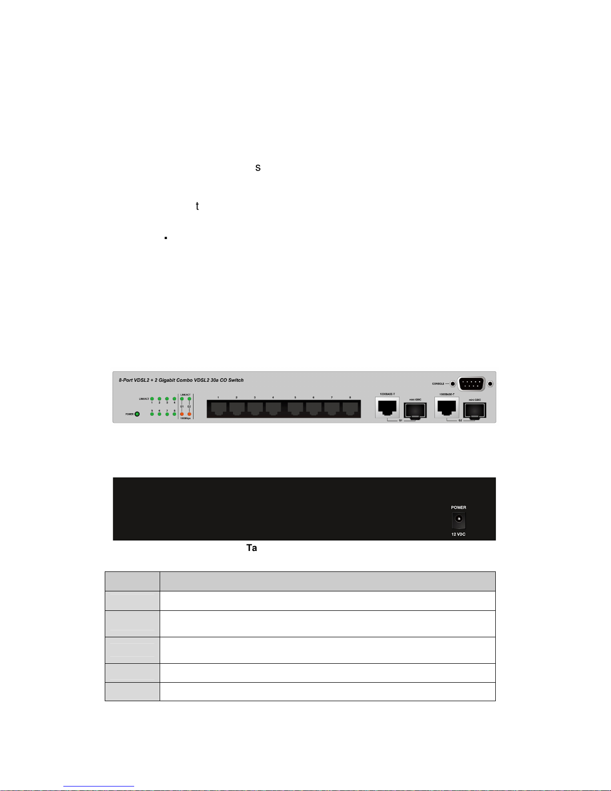
The front panel of 8-Port VDSL2 + 2 Gigabit Combo VDSL2 30a CO Switch
has 8 VDSL2 ports at the left, 2 Gigabit SFP slots and two 2 Gigabit copper
ports at the right. The product name is at the top on the left. Figure 2.2.2a
shows a front panel of this switch.
The rear panel has a power connector, and figure 2.2.2b shows a rear panel of
the switch.
Table 2.2.2c shows the port function of the switch.
Figure 2.2.2a Front Panel
Figure 2.2.2b Rear Panel
Table 2.2.2c Port Function
Port Function
VDSL2 Connect to VDSL2 interface.
RJ45
SFP
Console This is where you will connect RS232 console cable.
Power This is where you will connect the AC power adapter.
These 2 RJ-45 ports connect to network devices such as PCs,
print servers and other network peripherals at 1000 Mbps.
These 2 mini GBIC ports allows you to insert a SFP module for
1000Mbps fiber connection
-5-
Page 6
2.3. LED Function
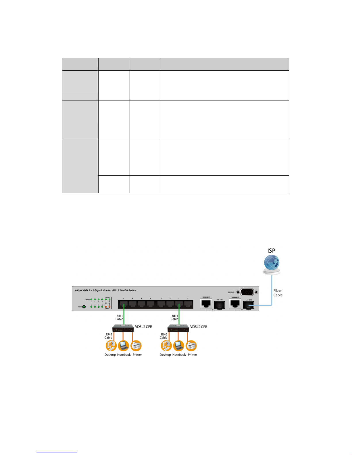
This section explains the definition of the Switch’s LEDs on the front panel.
Group LED Color Function
System
VDSL port
GE-LED
G1/G2
System
Link/Act
Link/Act
Speed Amber
Green
Green
Green
On : When the power supplied to the system
Off : Power off
Blinking: While system Booting /System
Self-Test / Firmware upgrade/Error.
Lights: When the link through the port is
successfully established.
Off : No-link detected for the port
Blinks: When the port is activating
transmitting data.
Lights: When the link through the port is
successfully established.
Off: for no-link detected for the port
Blinks: When the port is activating
transmitting data.
Lights: Link at 1000Mbps
Off: Link at 100/10Mbps or No Link
2.4. Installing the Switch
This section describes how to install and make connection to your VDSL2
Switch. The following diagrams shows the typical network configuration,
Read and perform the following procedures to install the switch,
-6-
Page 7

2.4.1. Pre-Installation Considerations
Gigabit Considerations:
If you will use the switch for Gigabit applications, keep in mind that the
maximum UTP cabling length of Category 5e cable is 328 feet (100 meters).
Positioning the switch:
When choosing a location for the switch, observe the following guidelines:
Keep enough ventilation space between the switch and the surrounding
objects.
Keep cabling away from sources of electrical noise, power lines, and
fluorescent lighting fixtures.
Do not stack free-standing switch more than four units high.
2.4.2. Desktop or Shelf Mounting
To install the switch on a desktop or shelf, simply complete the following steps:
Step 1 Place the switch on a desktop or shelf near an AC power source.
Step 2 Keep enough ventilation space between the switch and the surrounding
objects.
Note: When choosing a location, keep in mind the environmental restrictions
discussed in Chapter 4, Specifications.
Step 3 Connect the switch to network devices.
A. Connect one end of a standard network cable to the RJ11/RJ-45
ports on the front of the switch.
B. Connect the other end of the cable to the network devices such as
printer servers, VoIP, Video, workstations or routers.
Step 4 Supply power to the switch.
A. Connect one end of the power cable to the switch.
B. Connect the power cube end of the power cable to a standard wall
outlet.
2.5. Rack- Mount Placement
Before mounting the Switch, please read the following instructions carefully,
A) Elevated Operating Ambient - If installed in a closed or multi-unit rack
assembly, the operating ambient temperature of the rack environment may be
greater than room ambient. Therefore, consideration should be given to
installing the equipment in an environment compatible with the maximum
ambient temperature (Tma) specified by the manufacturer.
B) Reduced Air Flow - Installation of the equipment in a rack should be such
that the amount of air flow required for safe operation of the equipment is not
compromised.
C) Mechanical Loading - Mounting of the equipment in the rack should be
such that a hazardous condition is not achieved due to uneven mechanical
loading.
D) Circuit Overloading - Consideration should be given to the connection of
the equipment to the supply circuit and the effect that overloading of the
circuits might have on over current protection and supply wiring. Appropriate
consideration of equipment nameplate ratings should be used when
addressing this concern.
-7-
Page 8
E) Reliable Earthing - Reliable earthing of rack-mounted equipment should
be maintained. Particular attention should be given to supply connections
other than direct connections to the branch circuit (e.g. use of power strips)."
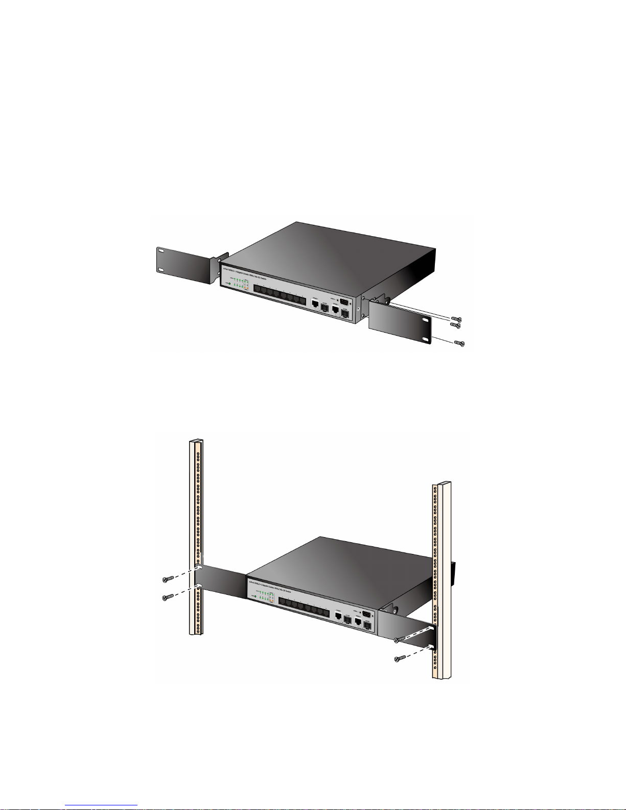
To mount the Switch in any standard-sized, 19-inch wide, 1U high rack, please
follow these instructions:
Place the Switch on a hard flat surface with the front panel facing you.
Attach a rack–mount bracket to one side of the Switch with the supplied
screws. Then attach the other bracket to the other side. (Figure 2.5.1)
Figure 2.5.1
Make sure the brackets are properly attached to the Switch.
Use the appropriate screws (not included) to securely attach the brackets to
your rack. (Figure 2.5.2)
Figure 2.5.2
-8-
Page 9
3. Configuration
3.1. Login
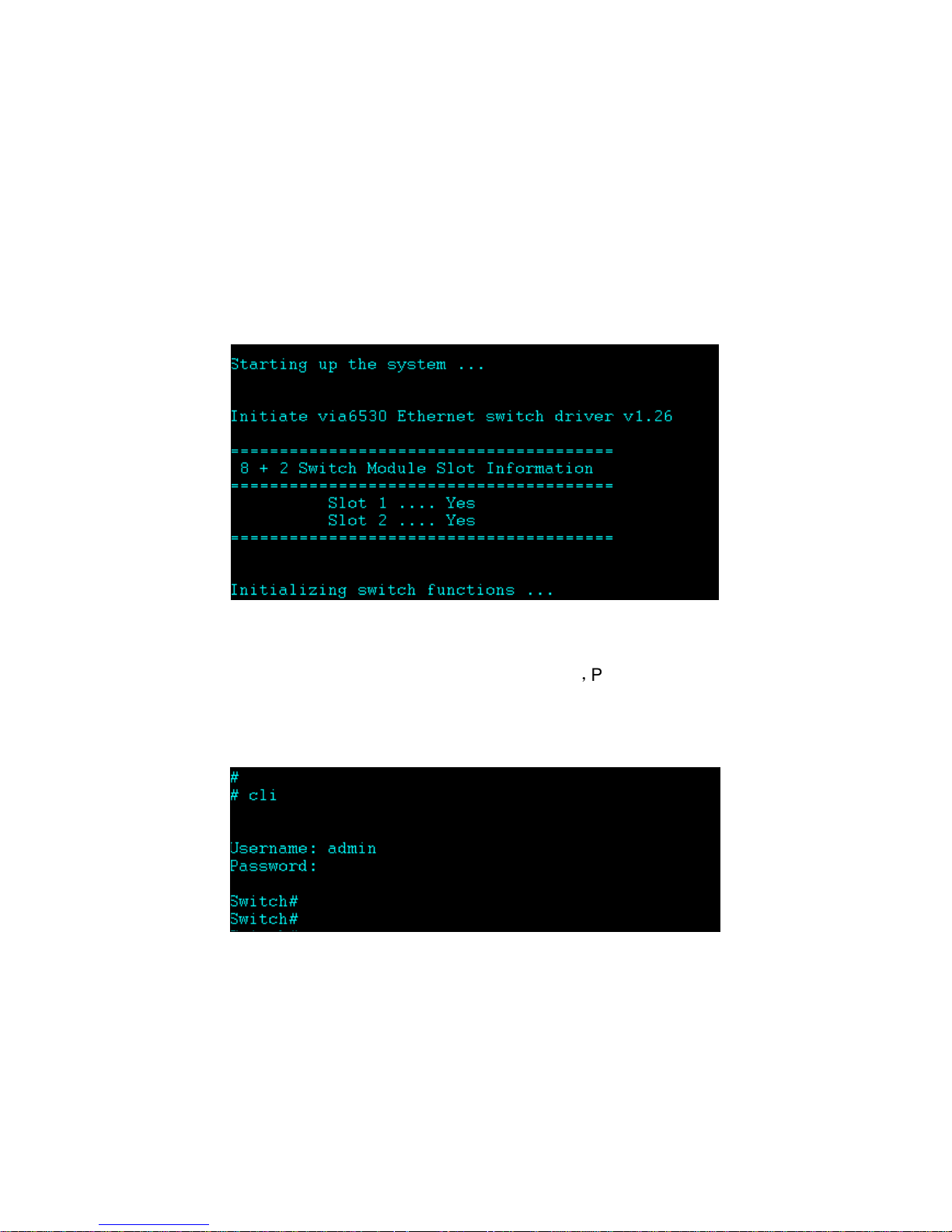
3.1.1. Power-On Self-Testing
The power-on self-testing is running immediately after the switch system is
powered up. The self-testing program diagnoses the hardware components of
a switch system. After hardware tests are all passed, the system will detect
and display the module slot status and start the initializations. The system will
be in ready state while the prompt is showing up.
3.1.2. Console Login
When you connect to the switch with a terminal emulation program, refer to the
information of: Baurate (bits/sec) 115200; Data Bits 8,Parity Check none ;Stop
Bits 1. Type “cli” if you want to log in the configuration of the switch .Enter a
user name and password to login to access the switch. The default user name
is “admin” and the password is empty.
3.1.3. Login with a Web Browser
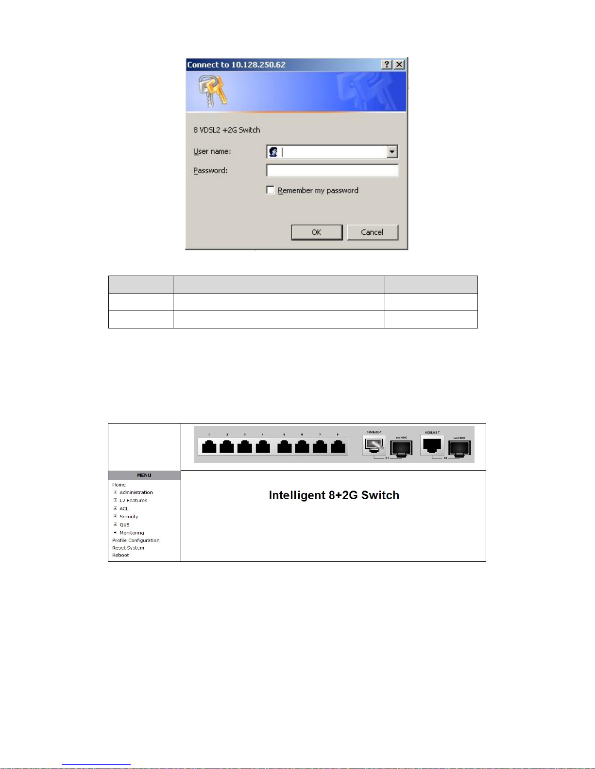
When you connect to the switch through a web browser, a login screen is
displayed. Enter a user name and password to login to access the switch.
-9-
Page 10
Items Option Default Value
User name Max:10, Min:0 characters, case sensitive admin
Password Max:10, Min:0 characters, case sensitive NULL
3.2. Web User Interface
3.2.1. Home
After user login verification, the homepage of the switch will be shown as
below.
3.2.2. Administration
There are many management functions can be set or performed if you expand
the submenus of Administrator in MENU area. These functions are:
IP Address
Switch Setting
Console Port Info
Port Configuration
SNMP Configuration
-10-
Page 11
Syslog Setting
Firmware Update
Configuration Backup
3.2.2.1. IP Address Setting
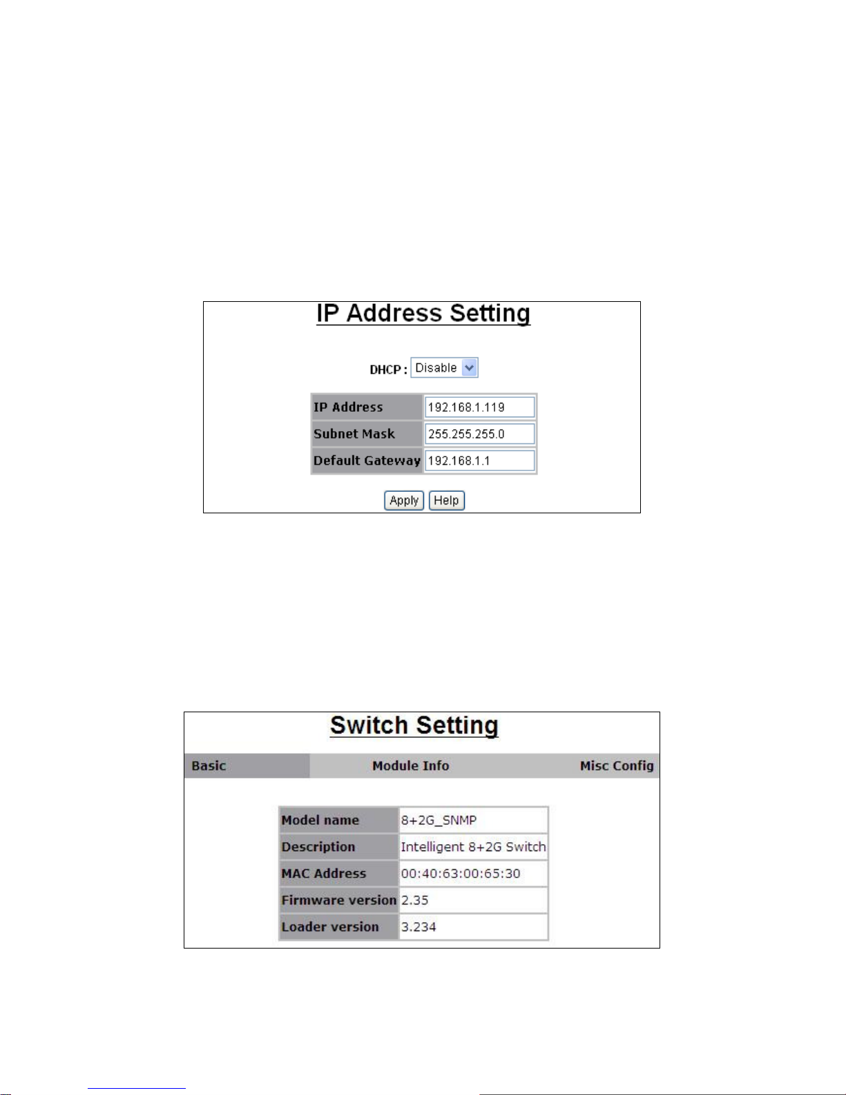
User can see and modify the IP address, subnet mask and default gateway in
this page, then clicks “Apply” button to confirm (save) the settings, then the
switch reboot must be done to activate the updates. The IP address can be
statically set or dynamically be assigned by the DHCP Server.
NOTE: If any of the value is changed in this field, reboot is necessary.
3.2.2.2. Switch Setting
Basic
All information in Basic is read only, user can’t modify the contents.
Model Name: Display the switch’s model name.
Description: Display the name of device type.
MAC Address: The unique hardware address assigned by manufacturer
(default)
Firmware Version: Display the switch’s firmware version.
-11-
Page 12
Module Info
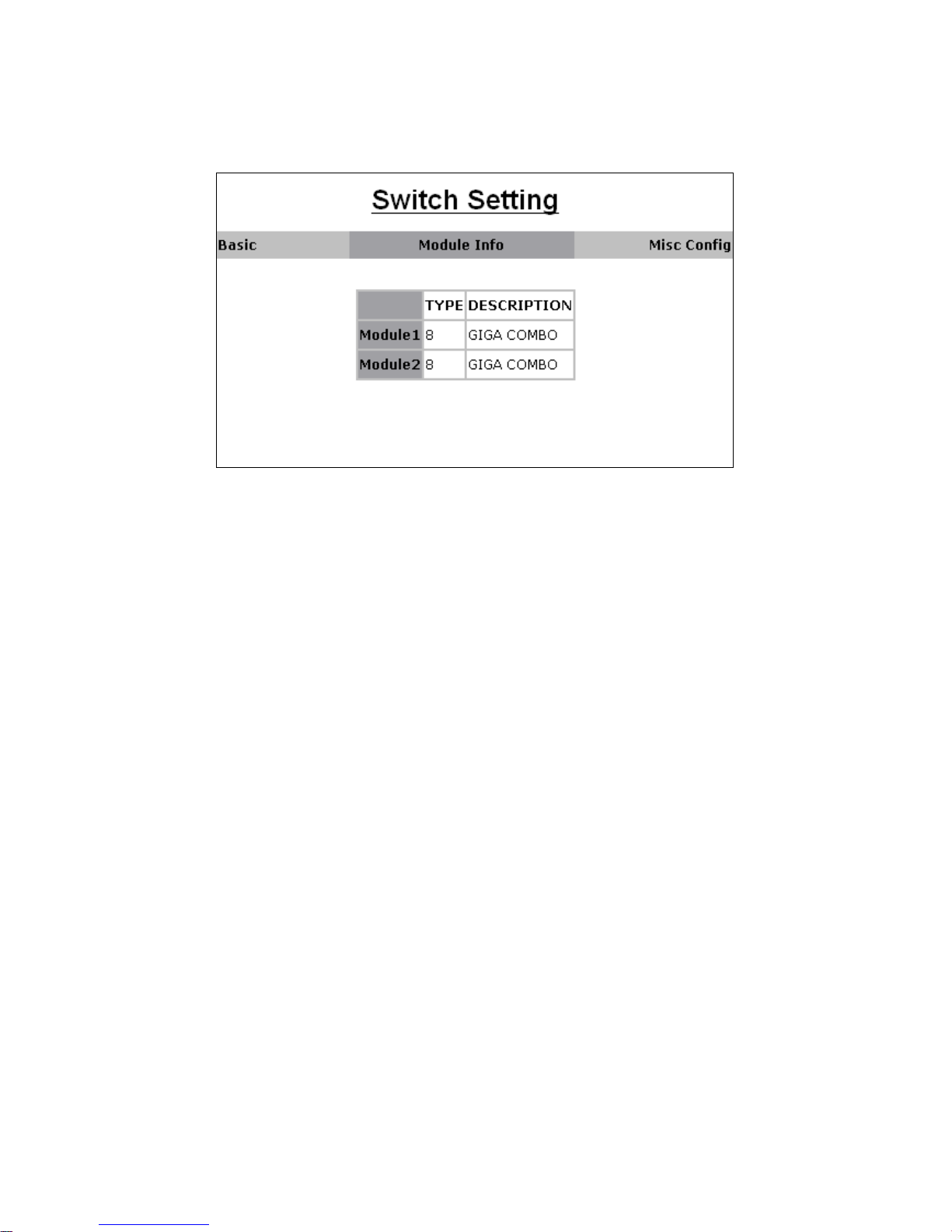
All information in this field is read only; user can’t modify its contents. It is only
to display the module port information.
MISC CONFIG
This page is to provide miscellaneous settings:
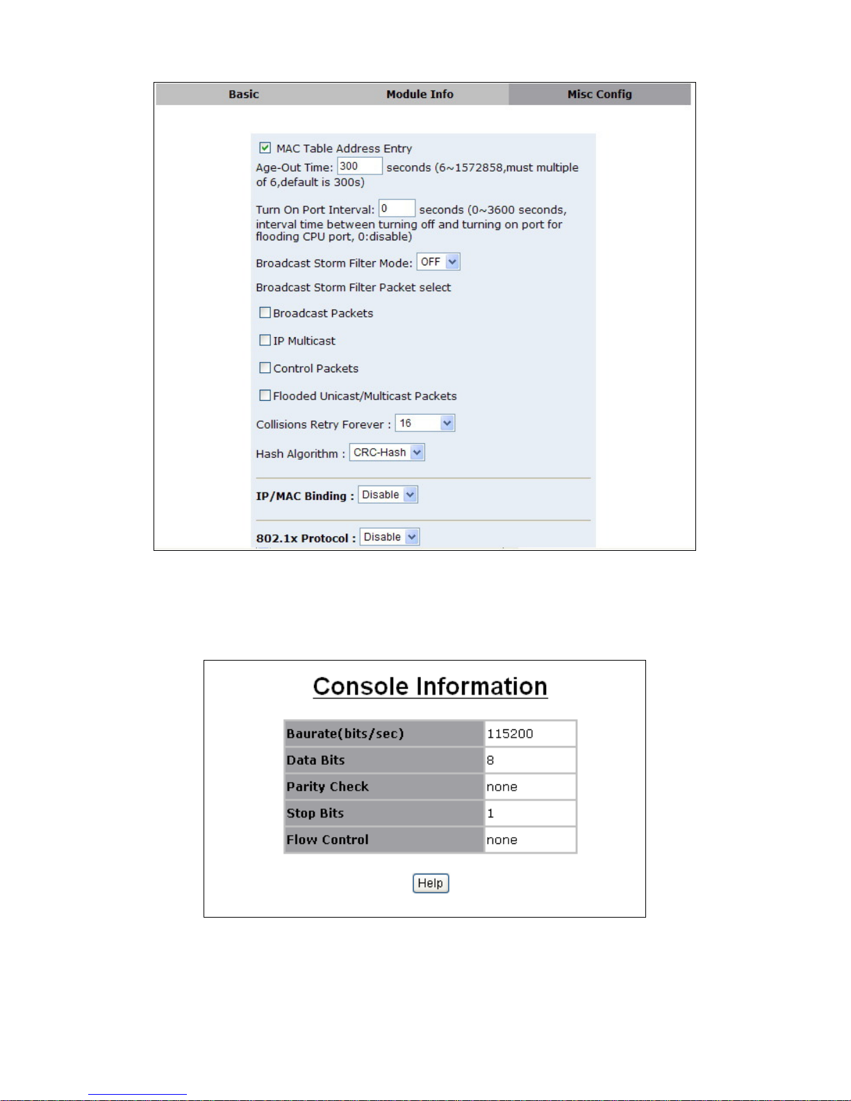
MAC Address Age-out Time: Type the number of seconds that an
inactive MAC address remains in the switch's address table. The valid
range is 6~1572858 seconds. Default is 300 seconds. The value is a
multiple of 6.
Turn on port interval: Set the interval time between turning off and
turning on when flooding CPU on this port. That’s to say, when flooding
CPU’s rate is faster than 3M this port will be disable, After turn on port
interval time later it will be enable automatically.
Broadcast Storm Filter Mode: To configure broadcast storm control,
enable it and set the upper threshold for individual ports. The threshold is
the percentage of the port's ingress bandwidth used by broadcast traffic.
When broadcast traffic for a port rises above the threshold you set,
broadcast storm control becomes active. The valid threshold value are 1/2,
1/4, 1/8, 1/16, and off.
Broadcast Storm Filter Packets Select: To select broadcast storm Filter
Packets type. If no packets type by selected, mean cannot filter any
packets .The Broadcast Storm Filter Mode will show OFF.
Collisions Retry Forever: In half duplex, collision-retry maximum is 16,
32, or 48 times and packet will be dropped if collisions still happen. In
default (Disable), system will retry forever if collisions happen.
Hash Algorithm: Select Hash Algorithm.
IP/MAC Bing: Enable or disable SMAC and SIP binding.
802.1x Protocol: Enable or disable 802.1 x protocols.
NOTE: Before you enable 802.1x or IP/MAC Binding, you should enable them
in this page
-12-
Page 13
3.2.2.3. Console Port Information
Console is a standard UART (RS-232) interface to communicate with serial
port. User can use windows HyperTerminal program to link the switch .Refer to
following information, user can’t modify the contents.
-13-
Page 14

3.2.2.4. Port Configuration
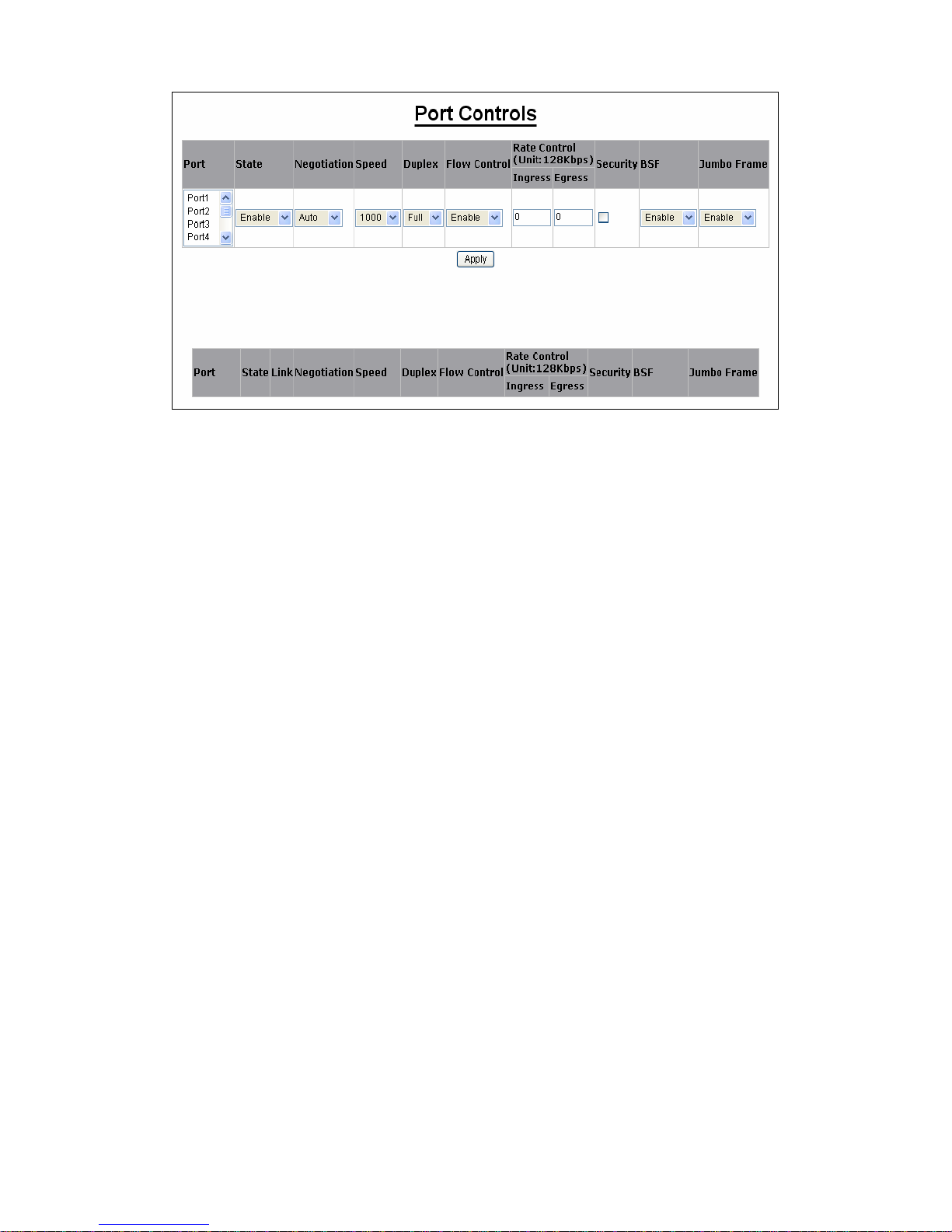
Port Controls
This webpage is to provide the display and modification for the port settings.
Use the dropdown in Port field to select one or multiple ports. The port settings
for the selected port(s) will be displayed in web. Use the other control fields in
the upper area to modify the port settings for the selected port(s). Press Apply
to save and activate the port settings.
State: User can enable or disable this port .When you disable this port, it
will not forward any packet.
Negotiation: User can set auto negotiation mode is Auto, Nway (specify
the speed/duplex on this port and enable auto-negotiation, in this model
link partner can be linked in full duplex and the device will link the partner
with the max capability); Force of per port: in this model the device’s
speed and duplex must be the same as the partner’s, if there is no auto
negotiation.
Speed: User can set 100Mbps or 10Mbps speed on Port1~Port8. User
can set 1000Mbps, 100Mbps or 10Mbps speed on mod1~mod2 (depend
on module card mode).
Duplex: User can set full-duplex or half-duplex mode of per port.
Flows control:
Full: User can set flow control function is enable or disable in full mode.
Half: User can set backpressure is enable or disable in half mode.
Rate Control: port1 ~ port 8, supports by-port ingress and egress rate
control. For example, assume port 1 is 10Mbps, users can set its effective
egress rate at 1Mbps and ingress rate at 500Kbps. Device will perform
flow control or backpressure to confine the ingress rate to meet the
specified rate.
Ingress: Type the port effective ingress rate. The valid range is 0 ~ 800 in
port 1~port 8, the unit is 128Kbps.
0: disable rate control;
1 ~ 800: valid rate value.
The Giga port’s valid range is 0 ~ 8000.
Egress: Type the port effective ingress rate. The valid range is 0 ~ 800 in
port 1~port 8, the unit is 128Kbps.
0: disable rate control;
1 ~ 800: valid rate value.
The Giga port’s valid range is 0 ~ 8000.
Port Security: A port in security mode will be “locked” without permission
of address learning. Only the incoming packets with source MAC already
existing in the address table can be forwarded normally. User can disable
the port from learning any new MAC addresses, then use the static MAC
addresses screen to define a list of MAC addresses that can use the
secure port. Enter the settings, and then click Apply to change on this
page.
BSF: User can disable/Enable port broadcast storm filtering option by port.
The filter mode and filter packets type can be select in Switch Setting >
Misc Config page.
Jumbo Frame: User can disable/Enable port jumbo frame option by port.
When port jumbo frame is enable, the port forward jumbo frame packet
-14-
Page 15
Port Sniffer
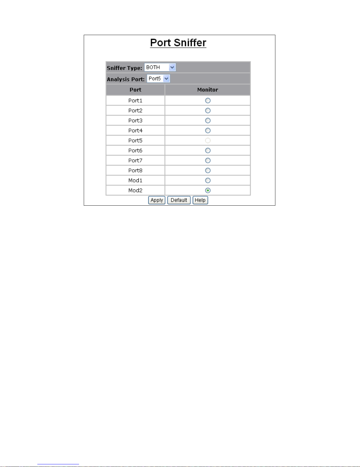
The Port Sniffer (mirroring) is a method for monitor traffic in switched networks.
Traffic through a port can be monitored by one specific port. That is, traffic
goes in or out a monitored port will be duplicated into sniffer port.
Sniffer Type: Select a sniffer mode: Disable / Rx / TX / Both.
RX: Packets goes in the Monitored port will be duplicated into analysis
port.
TX: Packets goes out the monitored port will be duplicated into analysis
port.
Both: Packets goes in or out the monitored port will be duplicated into
analysis port
Analysis (Monitoring) Port: It’ means Analysis port can be used to see
the traffic on another port you want to monitor.
Monitored Port: The port you want to monitor. The monitor port traffic will
be copied to Analysis port. You can select one monitor port in the switch.
User can choose which port that they want to monitor in only one sniffer
type.
Note: The Analysis port is dedicated for monitoring usage. That is to say, the
ordinary port function will be unavailable on Analysis port.
-15-
Page 16
Protected Port
There are two protected port groups. Ports in different groups can't
communicate each other.
In the same group, protected ports can't communicate each other, but can
communicate with unprotected ports. Unprotected ports can communicate with
any ports, including protected ports. In default, all ports are in Group1 and not
protected.
3.2.2.5. SNMP Configuration
Any Network Management platform running the Simple Network Management
Protocol (SNMP) can manage the switch; The SNMP is a Protocol that
governs the transfer of information between management station and agent.
NMS manages an SNMP-enabled network. It uses SNMP to manage and
monitor the network devices in the network. NMS can be a server that
manages the network or an application performing management function on a
device. NMS can send a request to an agent to query or modify one or more
variables. At the same time, NMS can receive traps sent by the agent to obtain
the status of the managed device. Currently, SNMP includes three versions:
SNMPv1, SNMPv2c and SNMPv3.
SNMPv1
SNMPv1 is the first version of the SNMP protocol, providing a minimum
network management function. The Structure of Management Information
(SMI) and MIB of SNMPv1 are rather simple and have many security defects.
SNMPv1 uses community name for authentication. A community name plays a
similar role as a password and can be used to control access from NMS to
-16-
Page 17
Agent. SNMP packets with community names that do not pass the
authentication on the device are simply discarded.
SNMPv2c
SNMPv2c also uses community name for authentication. Compatible with
SNMPv1, it extends the functions of SNMPv1. SNMPv2c provides more
operation modes such as GetBulk; it supports more data types such as
Counter32; and it provides various error codes, thus being able to distinguish
errors in more detail.
SNMPv3
By adopting User-based Security Model (USM) and View-based Access
Control (VACM) technologies, SNMPv3 enhances security. USM offers
authentication and privacy functions; while VACM controls users’ access to
specific MIBs.
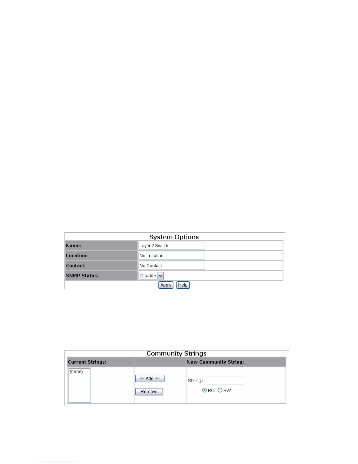
System options
User can define a name, location, and contact person for the switch or
enable/disable the SNMP function in this page .Fill in the system options data,
and then click Apply to update the changes. Name/ Location/ Contact: when
the network management station connect the agent correctly the “name”,
“location” and “contact” will be displayed in the SNMP tool . This information is
the description of the SNMP agent. Of course, we can modify this information
on the network management station. SNMP Status: Enable/Disable SNMP
Function
Community strings
If network management station wants to connect the SNMP agent with SNMP
v1 or SNMP v2, the community string will be served as passwords to visit the
MIB-object Information and the privilege of this access will be set by selecting
“RO” and “RW”. RO meats you can only read the MIB; RW meats you can read
and set the MIB.
-17-
Page 18
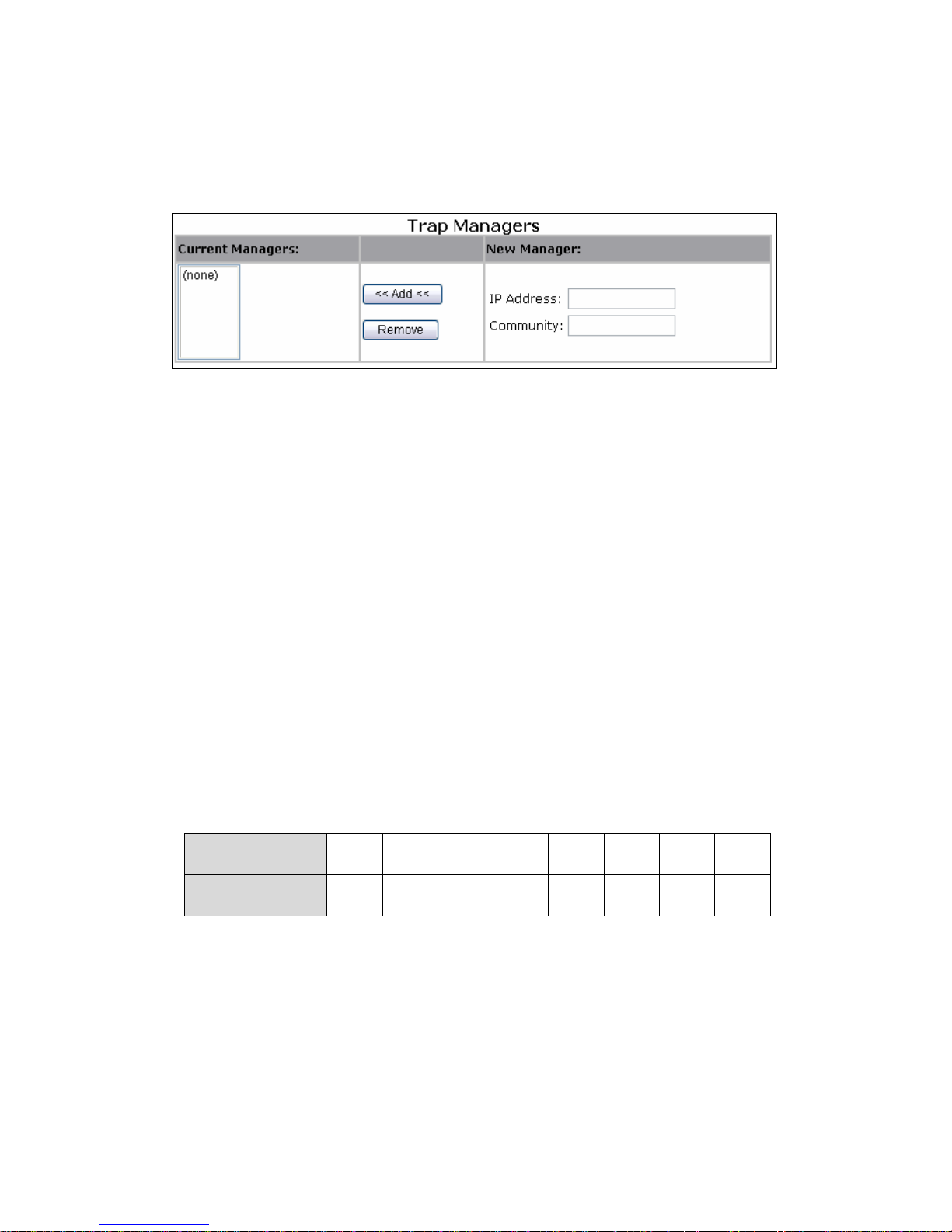
Trap Manager
Trap Manager is a management station that receives traps, the system alerts
generated by the switch. If no trap manager is defined, no traps are issued.
Create a trap manager by entering the IP address of the station and a
community string.
SNMPv3 Group
The group will be used in V3 access. In SNMP v3 group you can indicate
group name security model and group security
SNMPv3 View
V3 View only used on NNMP v3 .When the network management station visit
the SNMP agent, the V3 View is used to limit the privilege to visit the
Management Information Base. You can only view the MIB information (for
example: system name, interface) which included in the view you created.
Include/excluded indicate that the device feature OID include the Subtree ID or
not. View mask: A Subtree OID used with a View mask defines a view Subtree.
A View mask is in hexadecimal format. After it is converted to binary bits, each
bit corresponds to a node of the OID, where:
1 means full match, that is, the OID of the MIB object to be accessed must
be identical to the Subtree OID.
0 means wildcard match, that is, the OID of the MIB object to be accessed
can be different from the Subtree OID.
For example, provided the View mask 0xDB (11011011 in binary) and the
Subtree OID 1.3.6.1.6.1.2.1, their relationship is as shown as following. The
view determined by them includes all the nodes under the Subtree whose OID
is 1.3.*.1.6.*.2.1, where * represents any number.
Subtree OID 1 3 6 1 6 1 2 1
Subtree mask 1 1 0 1 1 0 1 1
-18-
Page 19
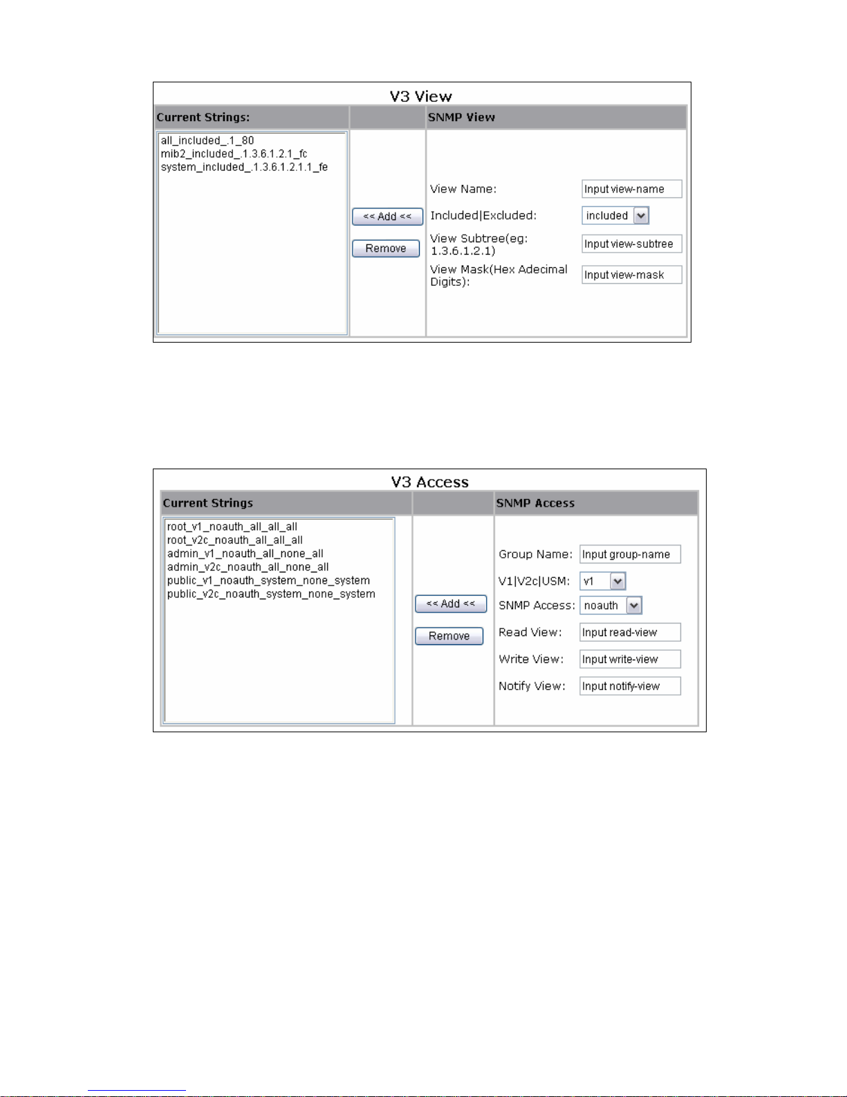
SNMPv3 Access
SNMPv3 Access control users’ access to management information. Only a
user with access rights can manage the objects. When a user accesses the
management information, he can access only the objects defined by the
corresponding MIB view.
SNMPv3 USM-User
USM introduces the concepts of username and group. You can set the
authentication and privacy functions. The former is used to authenticate the
validity of the sending end of the authentication packets, preventing access of
illegal users; the latter is used to encrypt packets between the NMS and Agent,
preventing the packets from being intercepted. USM ensures a more secure
communication between SNMP NMS and SNMP Agent by authentication with
privacy, authentication without privacy, or no authentication no privacy
-19-
Page 20
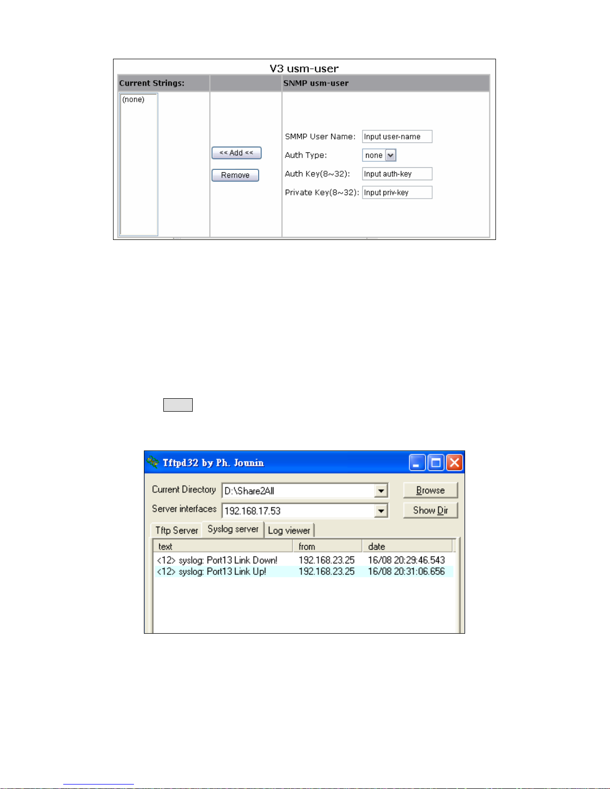
3.2.2.6. Syslog
This system supports syslog sent to a remote syslog server. Currently system
will do syslog for 3 events: cold start, warm start And link change. In this page,
user needs to setup the following parameters to activate the syslog: Syslog
server IP: The IP address of remote syslog server .Log level:
None: never send syslog message to syslog server, and Max Age
parameters of the root bridge, regardless of how it is configured.
Major: only send major syslog to syslog server, e.g.: link up/down, system
warm/cold start.
All: send all syslog messages to syslog server.
Then click Apply button to activate the syslog function. The following example
figure shows the syslog server application (e.g. Tftpd32.exe) got the messages
from switch which link status is changed on port13.
3.2.2.7. Firmware Update
This system supports firmware update through two different ways: TFTP and
HTTP.
TFTP Update
Use this page to assign a TFTP server IP address and an existing firmware
-20-
Page 21
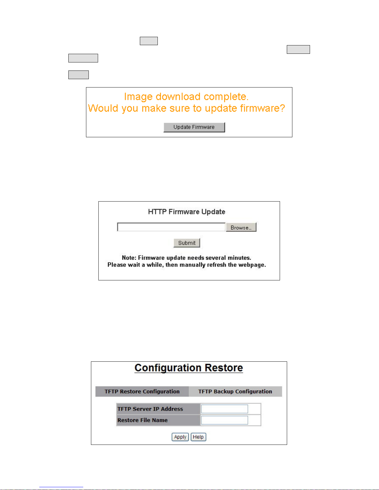
image file. Then press Apply button to start the firmware update process. The
firmware image will first update to the RAM area in system. Hit the Update
Firmware button to confirm to write to the system’s flash memory. When the
whole process is completed, system needs to be rebooted by pressing the
reboot button to activate the new firmware.
HTTP Update
An alternative for firmware updating is using HTTP transfer. Just like the file
copy in Windows, select the valid firmware image file to be uploaded to the
switch and hit Submit to start the updating process. This is easier than ordinary
TFTP file transfer. When the firmware image is completely uploaded, system
will automatically be rebooted.
3.2.2.8. Configuration Backup
Just like the firmware update, this system also supports configuration
backup/restore through either TFTP or HTTP transfer.
TFTP Restore Configuration
Use this page to assign a TFTP server IP address and an existing
configuration filename to be restored. Then press Apply button to start the
restore process.
-21-
Page 22
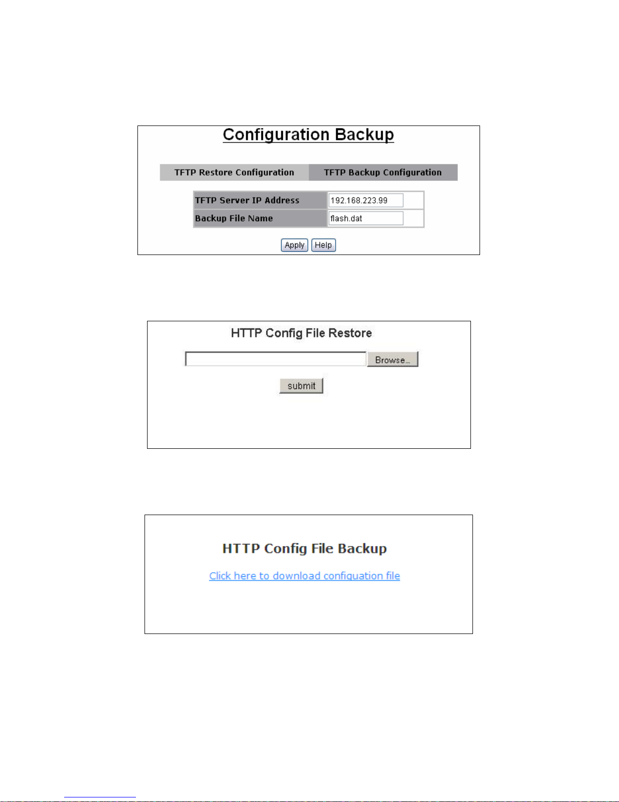
TFTP Backup Configuration
Use this page to assign a TFTP server IP address and a filename to be stored.
Then press Apply button to start the backup process.
HTTP Restore Configuration
Press “browse” button to select the destination file, then press “submit” button
to restore your configuration.
HTTP Backup Configuration
Press “Click here to download configuration file” to download current
configuration
-22-
Page 23

3.2.3. L2 Features
This switch provides the following L2 features:
VLAN Configuration
Trunking (Port Aggregation)
Forwarding & Filtering Spanning Tree (STP)
IGMP Snooping
Spanning Tree
DHCP Relay & Option 82
LLDP (optional)
3.2.3.1. VLAN Configuration
A Virtual LAN (VLAN) is a logical network grouping that limits the broadcast
domain. It allows you to isolate network traffic so only members of the VLAN
receive traffic from the same VLAN members. Basically, creating a VLAN from
a switch is logically equivalent of reconnecting a group of network devices to
another Layer 2 switch. However, all the network devices are still plug into the
same switch physically. This switch supports port-based, 802.1Q
(tagged-based) or no VLAN in web management page. In default, 802.1Q
VLAN is enabled for common and advanced operations. In VLAN configuration,
there are three categories to configure:
Static VLAN
GVRP VLAN
QinQ VLAN
Static VLAN
Port Based VLAN
When create a port based VLAN the traffic is forwarded to the member ports of
the same VLAN group. To create a port-based VLAN you can do as follows:
From the main menu, click Configure VLAN, and then click port-based
VLAN.
Click Add.
Type a name for the new VLAN.
Type a Group ID (between1-4094).
From the Available ports box, select ports to add to the switch
and click Add.
Click Apply.
-23-
Page 24
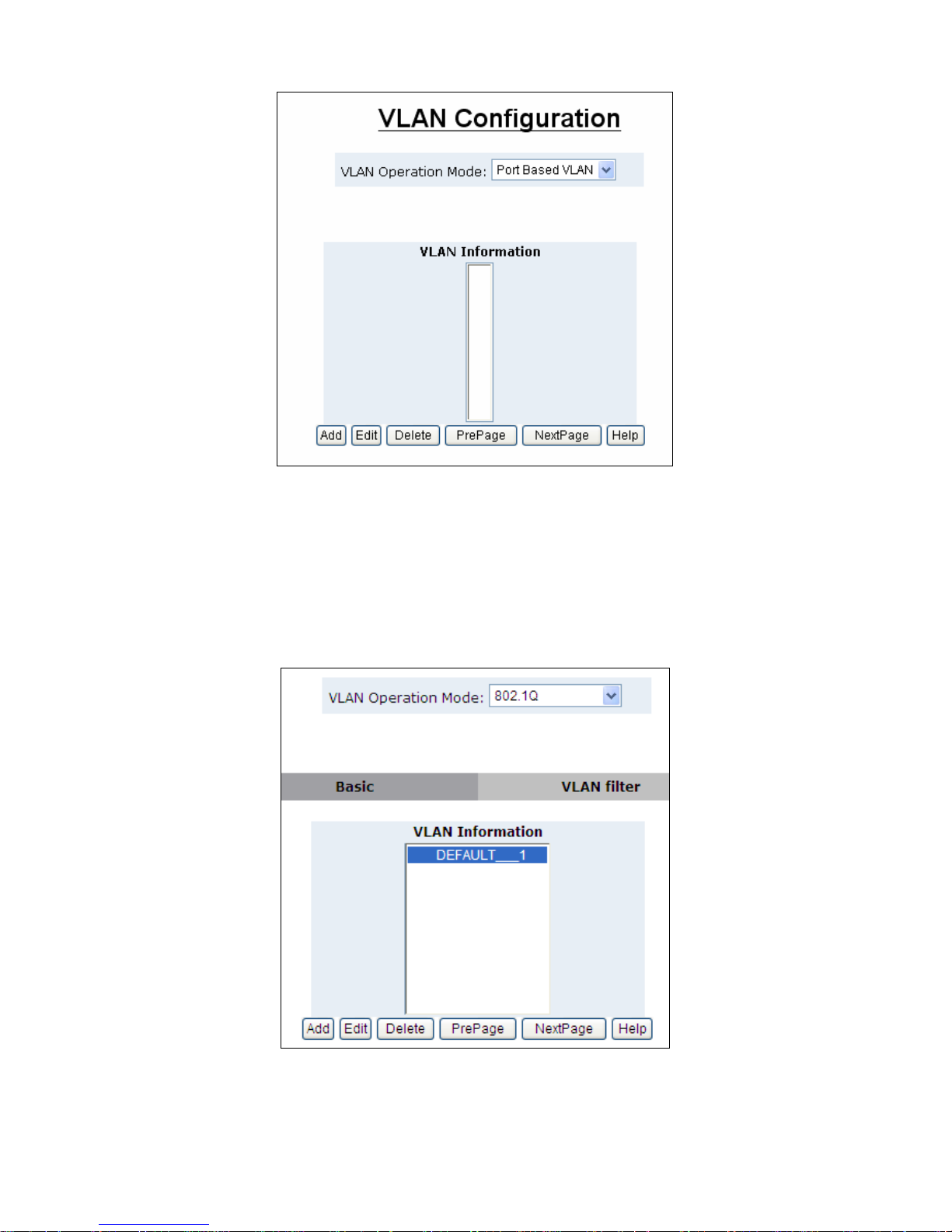
802.1Q VLAN
In this page, user can create 802.1Q (tag-based) VLAN. There are up to 512
VLAN groups to provide configuration. While VLAN Operation Mode is
changed to 802.1Q VLAN, all ports on the switch belong to default VLAN group
which VID is 1. The default VLAN group can’t be deleted. Use 802.1Q to set
the outgoing frames is VLAN-Tagged frames or not.
Tag: outgoing frames with VLAN-Tagged.
Untag: outgoing frames without VLAN-Tagged.
-24-
Page 25
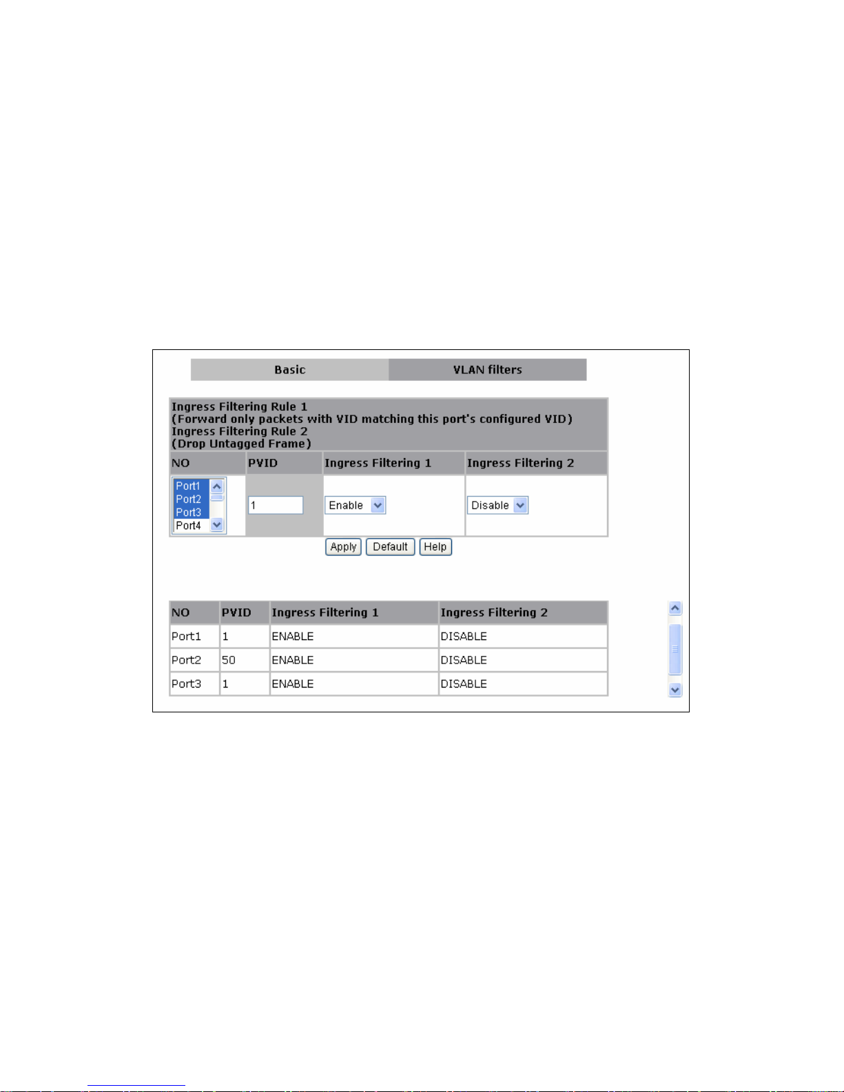
VLAN Filters
Port NO.: Port number(s) to be assigned to see or configure the settings.
Port VID (PVID): Port VLAN ID will be assigned to untagged traffic on a given
port. This feature is useful for accommodating devices that you want to
participate in the VLAN but that don’t support tagging. This switch allows user
to set one PVID for each port, the range is 1~4094, default PVID is 1. The
PVID must as same as the VLAN ID that the port belong to VLAN group, or the
untagged traffic will be dropped.
Ingress Filtering: Ingress filtering lets frames belonging to a specific VLAN to
be forwarded if the port belongs to that VLAN. This switch has two ingress
filtering rule as follows:
Ingress Filtering Rule 1: A forward only packet with VID matching this
port’s configured VID.
Ingress Filtering Rule 2: Drop Untagged Frame.
GVRP VLAN
GVRP Setting
GVRP (GARP VLAN Registration Protocol or Generic VLAN Registration
Protocol) is a protocol that facilitates control of virtual local area networks
(VLANs) within a larger network. GVRP conforms to the IEEE 802.1Q
specification, which defines a method of tagging frames with VLAN
configuration data. GVRP allows automatic VLAN configuration between the
switch and nodes. If the switch is connected to a device with GVRP enabled,
you can send a GVRP request using the VID of a VLAN defined on the switch,
the switch will automatically add that device to the existing VLAN GVRP can
be enabled per port basis. To enable GVRP function for a port, both global
GVRP and special port GVRP are required to configure.
-25-
Page 26
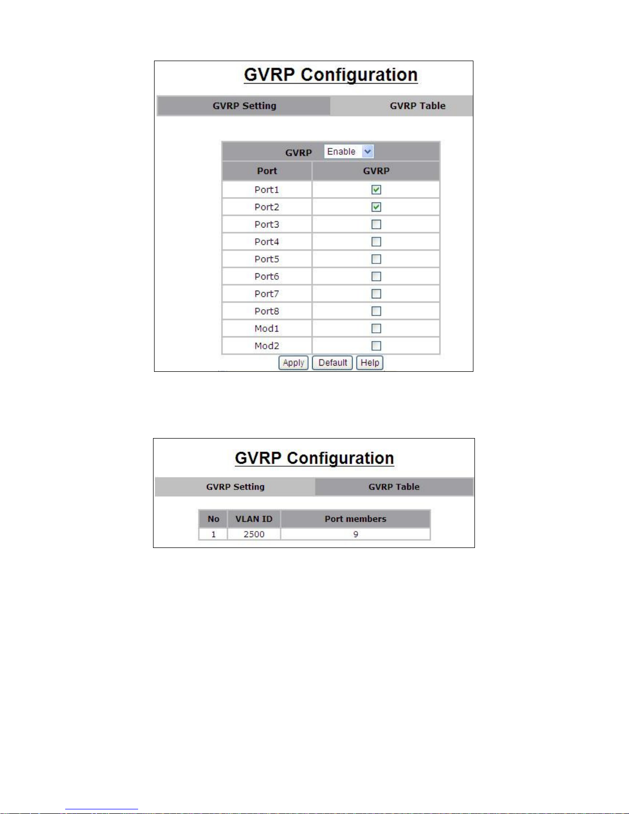
GVRP Table
In GVRP table the VLAN group(s) dynamically created by GVRP can be
displayed with VID and port member(s).
QinQ VLAN
QinQ Port Setting
Business customers of service providers often have specific requirements for
VLAN IDs and the number of VLANs to be supported. The VLAN ranges
required by different customers in the same service-provider network might
overlap, and traffic of customers through the infrastructure might be mixed.
Assigning a unique range of VLAN IDs to each customer would restrict
customer configurations and could easily exceed the VLAN limit (4096) of the
IEEE 802.1Q specification. Using the QinQ feature, service providers can use
a single VLAN to support customers who have multiple VLANs. Customer
VLAN IDs are preserved, and traffic from different customers is segregated
within the service-provider network, even when they appear to be in the same
-26-
Page 27
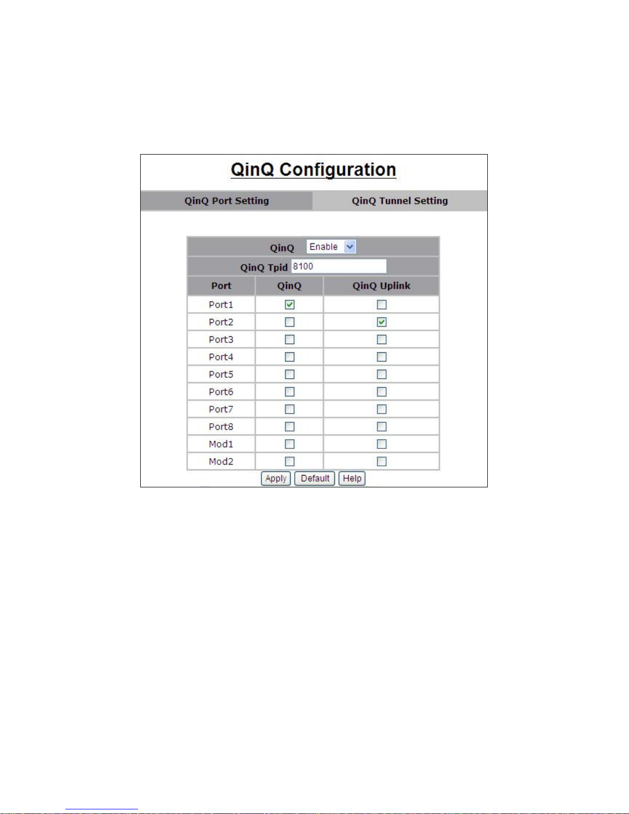
VLAN. Using QinQ expands VLAN space by using a VLAN-in-VLAN hierarchy
and retagging the tagged packets. A port configured to support QinQ is called
a QinQ user-port. A port configured to support QinQ Uplink is called
a QinQ uplink-port. To enable QinQ function, the global QinQ option, QinQ
Tpid and specified port-based QinQ User or Uplink port option need to be
configured.
QinQ Tunnel Setting
Virtual private networks (VPNs) provide enterprise-scale connectivity on a
shared infrastructure, often Ethernet-based, with the same security,
prioritization, reliability, and manageability requirements of private networks.
QinQ tunnel is a feature designed for service providers who carry traffic of
multiple customers across their networks and are required to maintain the
VLAN and Layer 2 protocol configurations of each customer without impacting
the traffic of other customers. When you configure QinQ tunnel, you assign the
QinQ user-port and uplink-port to a VLAN ID that is dedicated to QinQ tunnel.
To add QinQ tunnel, you first select QinQ Tunnel ID, then fill VLAN ID QinQ
dedicated to QinQ tunnel, and select user-port and uplink-port to be added to
QinQ tunnel.
-27-
Page 28
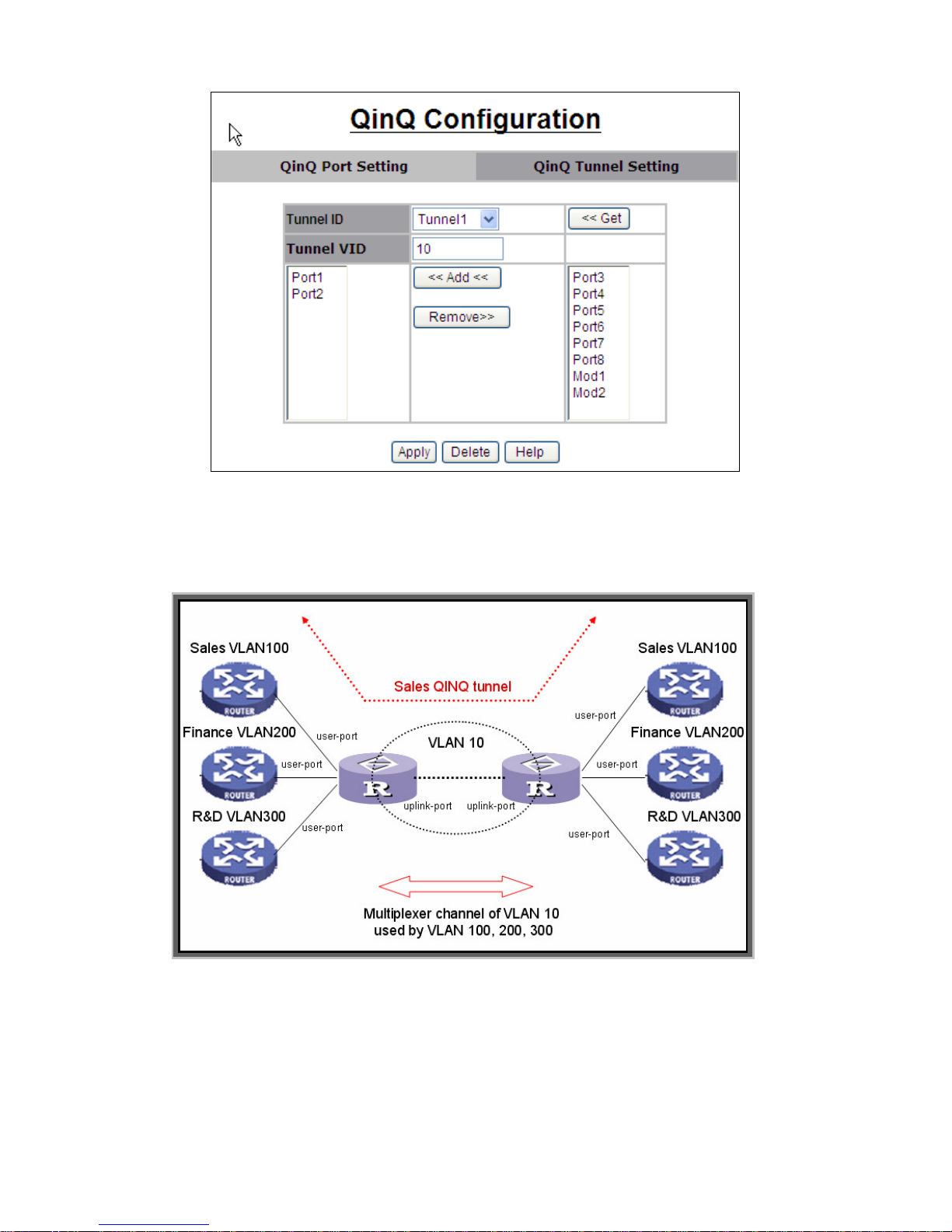
Note: Only the ports (user port, uplink port) not belong to any VLAN can be
added to the same tunnel
Following figure is an example of QinQ VLAN application
Refer to the figure of QinQ application in previous page, a QinQ tunnel using
VLAN100 wants to be created for Sales VLAN10 across the public network.
Port1 on left-side switch connects to Sales VLAN100 client. Port2 of switch
connects to the public network. The following commands needs to be set:
qinq enable
qinq tpid 8100
qinq userport enable 1
-28-
Page 29
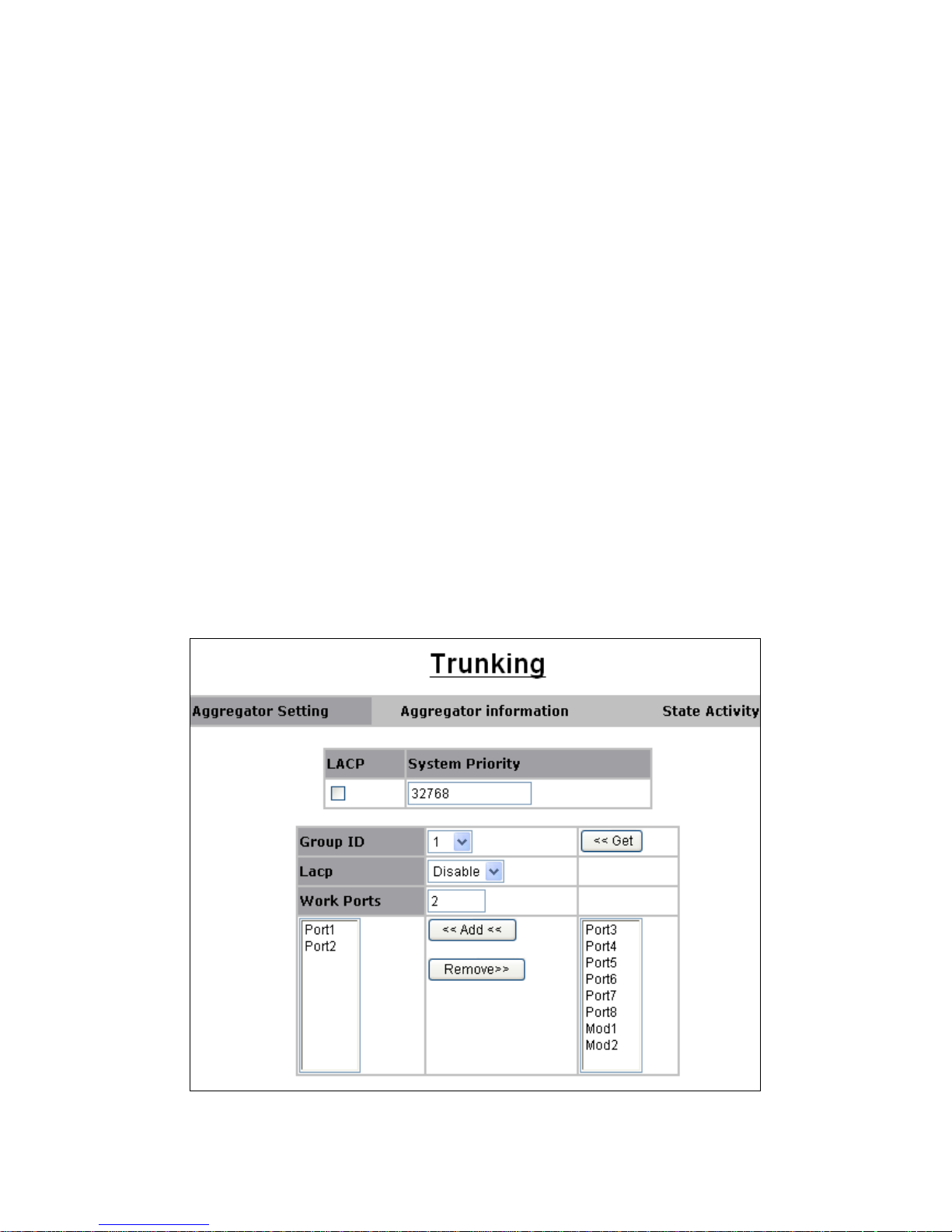
qinq uplinkport enable 2
qinq tunnel add 1 10 1, 2
3.2.3.2. Trunking
The Link Aggregation Control Protocol (LACP) provides a standardized means
for exchanging information between Partner Systems on a link to allow their
Link Aggregation Control instances to reach agreement on the identity of the
Link Aggregation Group to which the link belongs, move the link to that Link
Aggregation Group, and enable its transmission and reception functions in an
orderly manner. In conclusion, Link aggregation lets you group up to eight
consecutive ports into a single dedicated connection. This feature can expand
bandwidth to a device on the network. LACP operation requires full-duplex
mode, more detail information refers to IEEE 802.3ad.
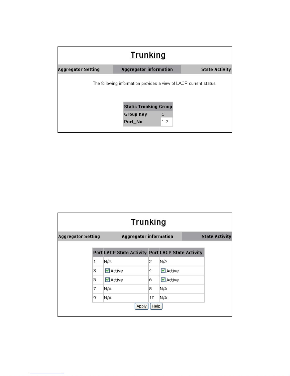
System Priority: A value used to identify the active LACP. The switch with the
lowest value has the highest priority and is selected as the active LACP.
Group ID: There are up to 7 trunk groups can be configured. Choose the
"Group ID" and click << Get to retrieve the trunk group.
LACP: If enabled, the group is LACP static trunk group. If disabled, the group
is local static trunk group. All ports support LACP dynamic trunk group. If
connecting to the device that also supports LACP, the LACP dynamic trunk
group will be created automatically.
Work ports: Allow max eight ports can be aggregated at the same time. If
LACP static trunk group, the exceed ports is standby and able to aggregate if
work ports fail. If local static trunk group, the number must be as same as the
group member ports. Select the ports to join the trunk group. Allow max 8 ports
can be aggregated at the same time. If LACP enabled, you can configure
LACP Active/Passive status in each port on State Activity page.
-29-
Page 30
In aggregator information: The static LACP static trunk group will be displayed
as follows:
In State Activity:
Active (select): The port automatically sends LACP protocol packets.
N/A (no select): The port does not automatically sends LACP protocol
packets, and responds only if it receives LACP protocol packets from the
opposite device.
1. A link that has either two active LACP ports or one active port can
perform dynamic LACP trunking. A link has two N/A LACP ports will not
perform dynamic LACP trunking because both ports are waiting for and
LACP protocol packet from the opposite device.
2. If you are active LACP’s actor, when you select trunking port, the active
status will be created automatically.
3.2.3.3 Forwarding and Filtering
In this submenu, the following functions related to forwarding and filtering are
provided:
-30-
Page 31
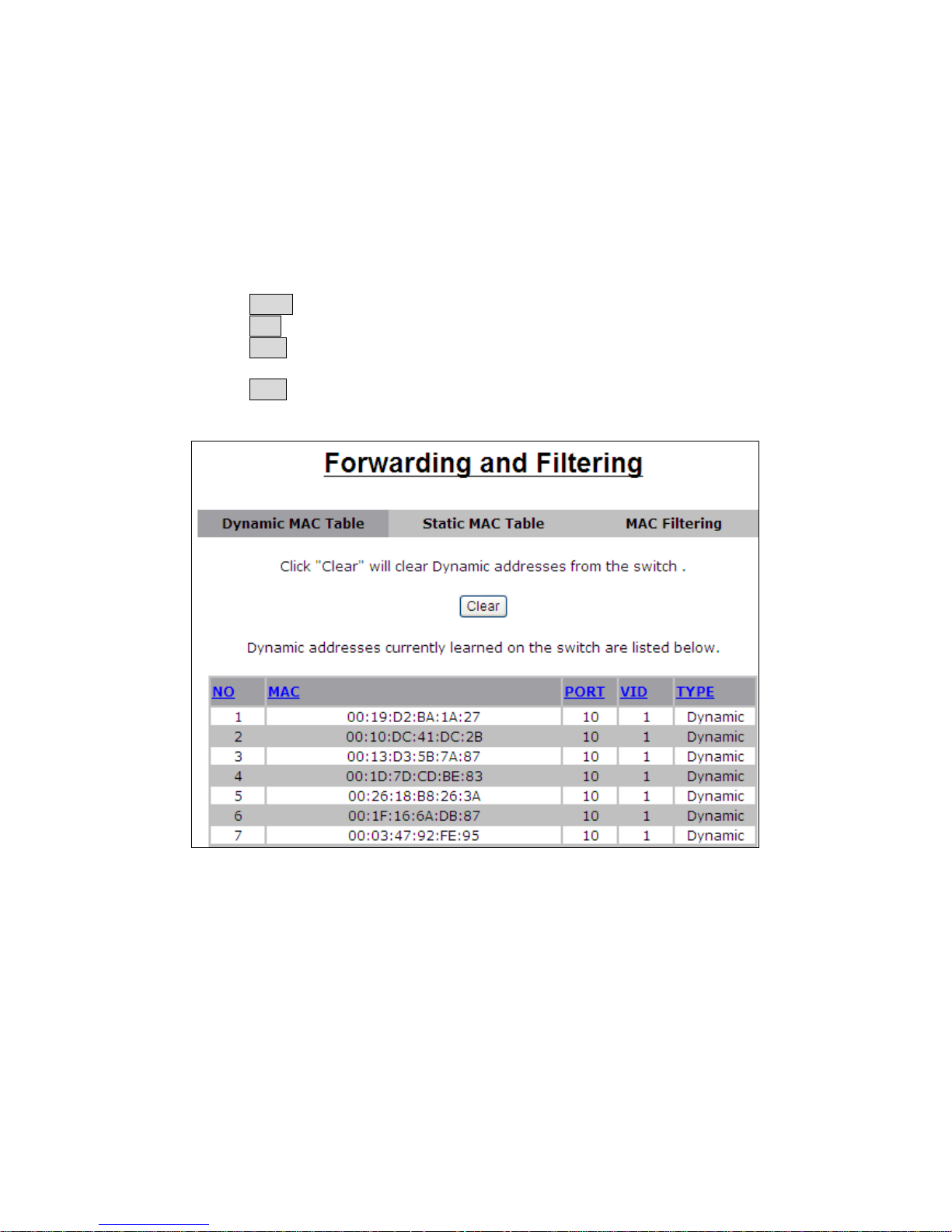
Dynamic MAC Table
Static MAC Table
MAC Filtering
Dynamic MAC Table
The switch will dynamically learn the device’s MAC address when it
corresponding with the switch. MAC address will be stored in MAC address
table. Dynamic MAC Table shows the MAC addresses learned by the switch.
The table will be shown by pages if larger than 500 MAC Addresses. You can
set the age-out time of Dynamic MAC table in switch setting:
Click Clear to clear Dynamic MAC address table.
Click Top to show the first page of MAC address table.
Click Prev to show the previous page of MAC address table. If there is
nothing to shown or NO is 1, it is the first page.
Click Next to show the next page of MAC address table. If there is nothing
to shown, it is the end page.
Static MAC Table
When you add a static MAC address, it permanently remains in the switch's
address table, regardless of whether the device is physically connected to the
switch. This saves the switch from having to re-learn a device's MAC address
when the disconnected or powered-off device is active on the network again.
This table can associate with the Security field in Port Controls configuration to
achieve the access control by source MAC / port / VID binding. That is only
ingress traffic with matched lookup (with specified MAC address, port number
and VID) in this table can be allowed to access to the switch.
The following parameters can be associated to setup the Static MAC table:
MAC Address: Static MAC address in a MAC entry
-31-
Page 32
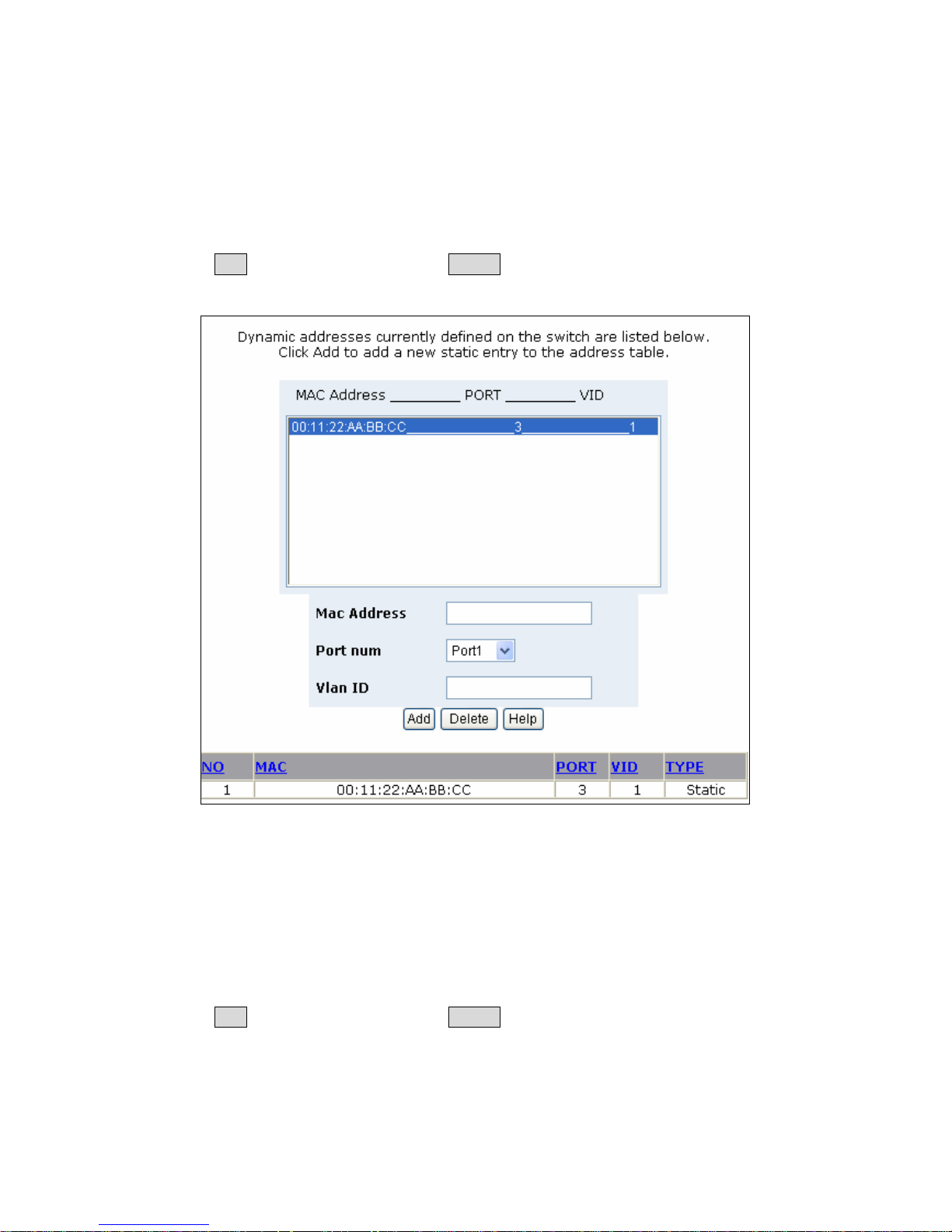
Port number: Switch port number to associate with the MAC address in a
MAC entry
VLAN ID: If tag-based (IEEE 802.1Q) VLANs are enabled, static MAC address
can be associated with individual VLANs. Type the VID in this field to associate
with the MAC address.
Click Add to add a new entry. Click Delete to remove a specified entry.
The MAC entries in this table can be sorted by clicking the column NO / MAC /
PORT / VID / TYPE.
MAC Filtering
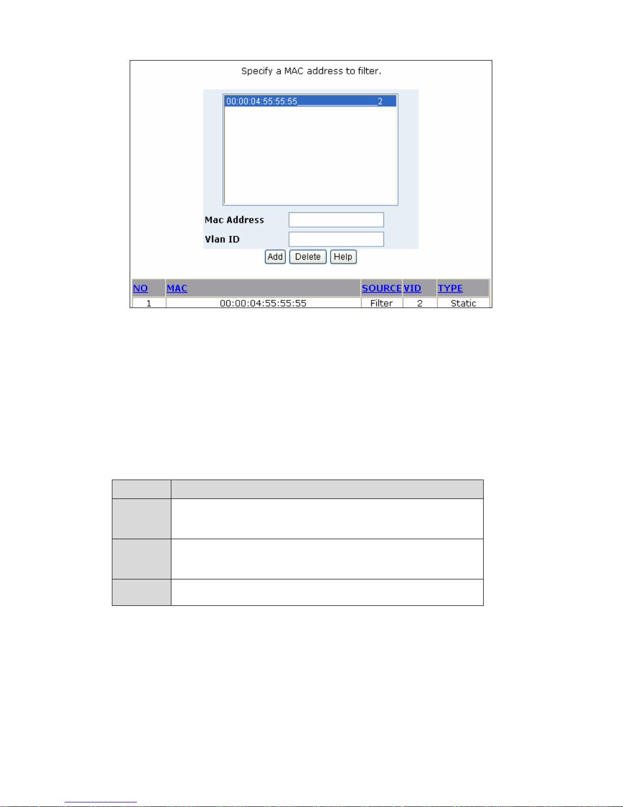
MAC address filtering allows the switch to drop unwanted traffic. Traffic is
filtered based on the destination MAC addresses.
MAC Address:
MAC address that wants to be filtered.
VLAN ID: If tag-based (802.1Q) VLAN are enabled, type the VID in this field to
associate with the MAC address.
Click Add to add a new entry. Click Delete to remove a specified entry.
The MAC entries in this table can be sorted by clicking the column NO / MAC /
PORT / VID / TYPE.
-32-
Page 33
3.2.3.4 IGMP Snooping
This switch supports multicast IP, one can enable IGMP protocol on web
management’s switch setting advanced page, then display the IGMP snooping
information in this page, you can view difference multicast group, VID and
member port in here, IP multicast addresses range from 224.0.0.0 through
239.255.255.255. The Internet Group Management Protocol (IGMP) is an
internal protocol of the Internet Protocol (IP) suite. IP manages multicast traffic
by using switches, routers, and hosts that support IGMP. Enabling IGMP
allows the ports to detect IGMP queries and report packets and manage IP
multicast traffic through the switch. IGMP have three fundamental types of
message as follows:
Message
Description
A message sent from the queries (IGMP router or switch)
Query
asking for a response from each host belonging multicast
group.
A message sent by a host to the queries to indicate that the
Report
host wants to be or is a member of a given group indicated
in the report message.
Leave
Group
A message sent by a host to the queries to indicate that the
host has quit being a member of a specific multicast group.
-33-
Page 34
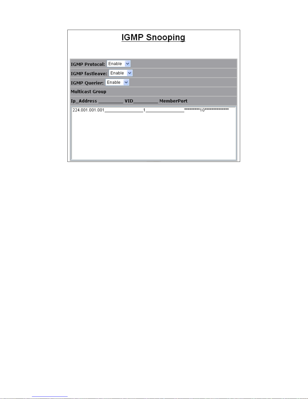
IGMP protocol: Enable/disable IGMP snooping.
IGMP fast leave: Enable/disable IGMP snooping fast leave. If enable, switch
will fast delete member who send leave report, else wait one second.
IGMP Querier: Enable/disable IGMP snooping querier. If select disable, the
switch can’t send query report.
3.2.3.5 Spanning Tree
STP provides tree topology for any arrangement of bridges and it also provides
a unique path between end stations on a network. In this way, it eliminates
loops.
Loops occur when alternate routes exist between hosts. Loops in an extended
network can cause bridges to forward traffic indefinitely, resulting in increased
traffic and reduced network efficiency. The device supports the following
Spanning two Protocol versions:
STP: Provides a single path between end stations, avoiding and
eliminating loops.
Multiple STP (MSTP)
Provides full connectivity for packets allocated to any VLAN. MSTP is based
on RSTP. In addition, MSTP transmits packets assigned to various VLANs
through different MST regions. MST regions act as a single bridge.
In STP, when the system detects L2 loops, it attempts to mitigate them by
preventing the involved port from transmitting traffic. Since loops exist on a
per-L2-domain basis, a problematic situation may occur wherethere is a loop in
VLAN A and no loop in VLAN B. If both VLANs are on Port X, and regular STP
wants to mitigate the loop, it stops traffic on the entire port, even for VLAN B
traffic, where there is no need. Multiple Spanning Tree Protocol (MSTP) solves
this problem by enabling several STP instances, so that it is possible to
detect/mitigate loops separately in each instance. By associating instances to
-34-
Page 35
VLANs, each instance is associated with the L2 domain on which it performs
loop detection/mitigation. This enables a port to be stopped in one instance (for
example, in the above example, traffic from VLAN A) while traffic can remain
active in another domain where no loop was seen (in VLAN B in the above
example).
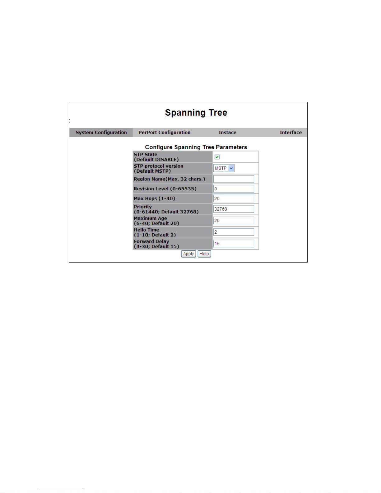
3.2.3.5.1
System configuration
STP state: Enable/disable STP on the device
STP protocol version: Select the STP mode or MSTP mode
Region Name:
Revision Level: Enter an unsigned 16-bit number that identifies the
revision of the current MST configuration. The possible field range
0-65535.
Max Hops — Enter the total number of hops that occur in a specific
region before the BPDU is discarded. Once the BPDU is discarded,
the port information is aged out. The possible field range is 1-40.
Priority: You can change priority value, A value used to identify the
root bridge. The bridge with lowest value has the highest priority and
is selected as the root. Value range <0- 61440>, the value must be in
steps of 4096. Default value is 32768.
Max Age: You can change Max Age value. The maximum age of
received protocol information before it is discarded. Value range
<6-40>. Default value is 20.
Hello Time: You can change Hello time value. The time interval
between the transmission of Configuration BPDUs by a Bridge that is
attempting to become the Root or is the Root. Value range <1-10>.
Default value is 2
Forward Delay: You can change forward delay time. The time spent
by a Port in the Listening State and the Learning State before moving
-35-
Page 36
to the Learning or Forwarding State, respectively. It is also the value
used for the ageing time of dynamic entries in the Filtering Database,
while received BPDU indicate a topology change. Value range <430>. Default value is 15.
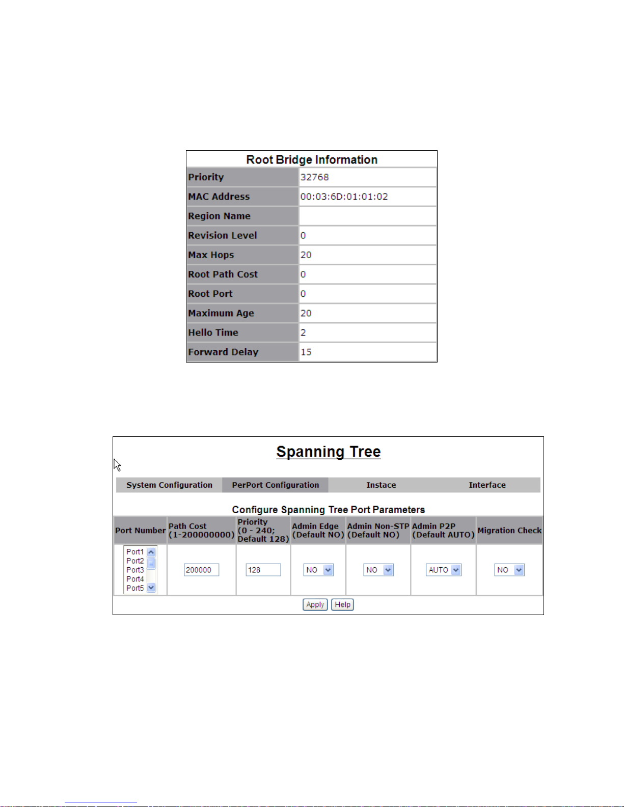
You can view STP information about the Root Bridge. Such as following
screen
.
3.2.3.5.2
PerPort configuration
The following parameters can be configured on each port, click Apply button to
set the values
-36-
Page 37
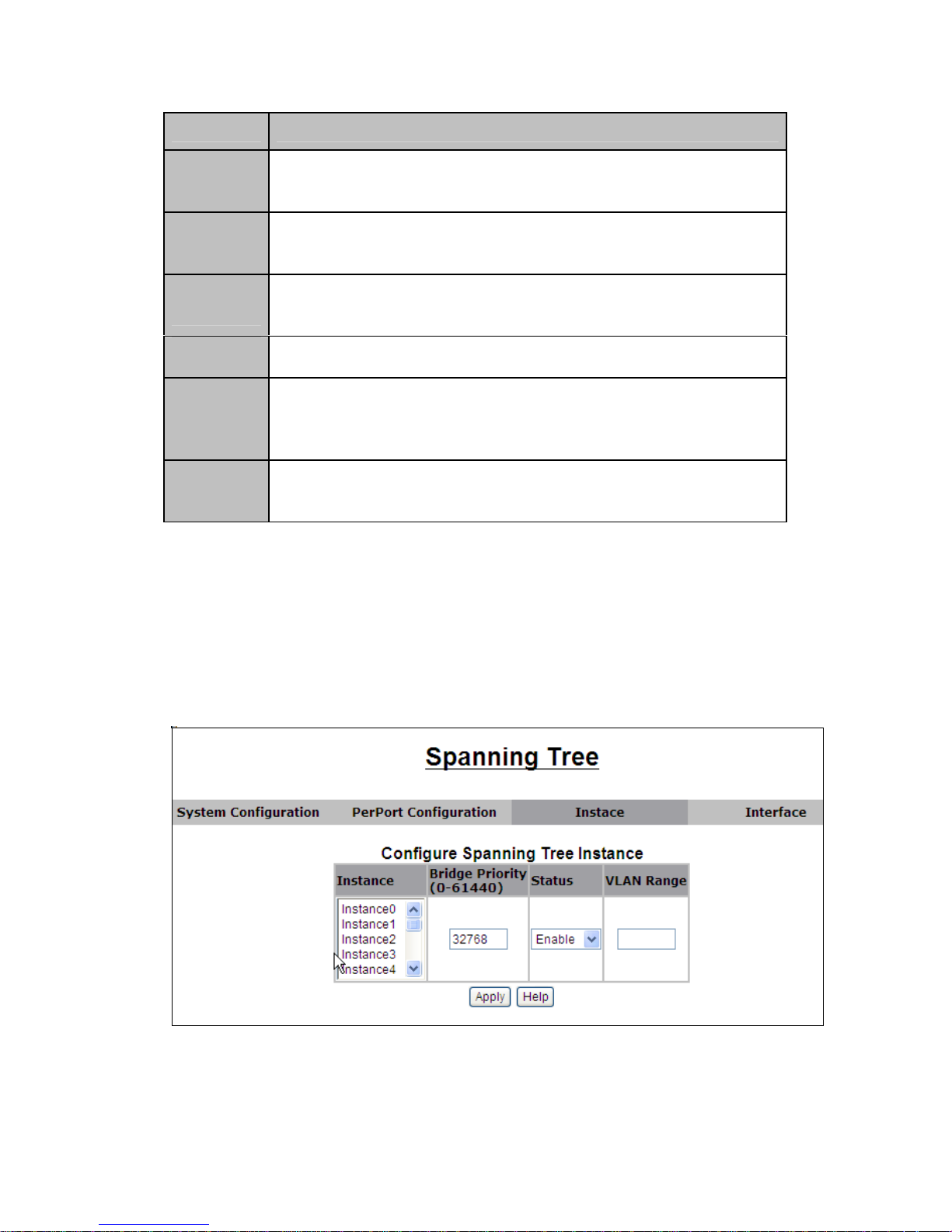
Parameter
Path Cost
Priority
Admin
Edge
Admin
non-STP
Admin
P2P
Migration
3.2.3.5.3
Description
The contribution of the path through this port, when the port is the
root port, to the total cost of the path to the root for this bridge.
Value range <1-65535>.
You can make it more or less likely to become the root port, the
lowest number has the highest priority. Value range <0-240>, the
value must be in steps of 16. Default value is 128.
Indicates if this port is the edge port. Once configured as an edge
port, the port state immediately transitions from discarded to
forwarding state.
Enable/disable STP on designated port
Indicates if this port is a point-to-point link. If you connect a port
to another port though a point-to-point link and the local port
becomes a designated port, it negotiates a rapid transition with
the other port to ensure a loop-free topology.
If MSTP switch has Link STP switch, Enable Migration Check to
Change the port status to MSTP mode when the STP switch
power down or be moved.
Instance
The VLAN to MST Instance Page enables mapping each VLAN to a Multiple
Spanning Tree Instance (MSTI). For devices to be in the same region they
must have the same mapping of VLANs to MSTIs. Note that the same MSTI
can be mapped to more than one VLAN, but each VLAN can only have one
MST Instance attached to it. Configuration on this page (and all of the MSTP
pages) applies if the system STP mode is MSTP.
Instance ID — Select an MST instance to be displayed and defined
Bridge Priority — Enter the selected spanning tree instance device priority.
Value range is from 0 to 61440, the value must be in steps of 4096. Default
-37-
Page 38
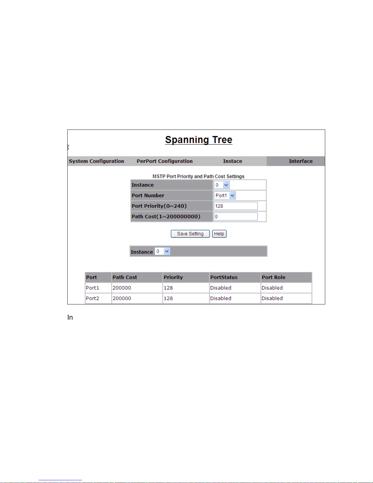
value is 32768.
Status —You can choose the value of Enable if you want the Instance to be
enable. Value range is Disable or Enable. Default value is Instance 0 Enable,
Other Disable.
VLAN Range — Displays the VLANs mapped to the selected instance. Each
VLAN belongs to a single instance.
3.2.3.5.4
Interface
The MST Interface Settings Page enables configuring MSTP per port per MST
instance, as well as receiving information that has currently been learned by
the protocol, such as the designated bridge per MST instance.
Instance ID — Select the MST Instance to be configured.
Port Number — Select whether to display the list of ports or LAGs.
Priority —You can change the port priority of the Instance , Value range is from
0 to 240, the value must be in steps of 16. Default value is 128.
Path Cost —You can change the port post cost of the Instance , Value range is
from 1 to 200000000, Default value is 2000000.
Port State — Displays the MSTP status of the specific port on a specific MST
instance. The possible options are:
Disabled — STP is currently disabled.
Blocking — Port on this instance is currently blocked and cannot
forward traffic or learn MAC addresses.
Listening — Port on this instance is in Listening mode. The port cannot
forward traffic nor can it learn MAC addresses.
Learning — Port on this instance is in Learning mode. The port cannot
-38-
Page 39
forward traffic, however it can learn new MAC addresses.
Forwarding — Port on this instance is in Forwarding mode. The port
can forward traffic and learn new MAC addresses.
Port Role — Displays the port role, per port per instance, assigned by the
MSTP algorithm in order to provide STP paths. The possible options are:
Root — Forwarding packets through this interface provides the lowest
cost path to forward packets to the root device.
Designated — Device is attached to the LAN through this interface.
Alternate — Interface provides an alternate path to the root device
from the root interface.
Backup — Interface provides a backup path to the designated port
path toward the Spanning Tree leaves. Backup ports occur only when
two ports are connected in a loop by a point-to-point link. Backup ports
also occur when a LAN has two or more connections connected to a
shared segment.
Disabled — Interface is not participating in the Spanning Tree.
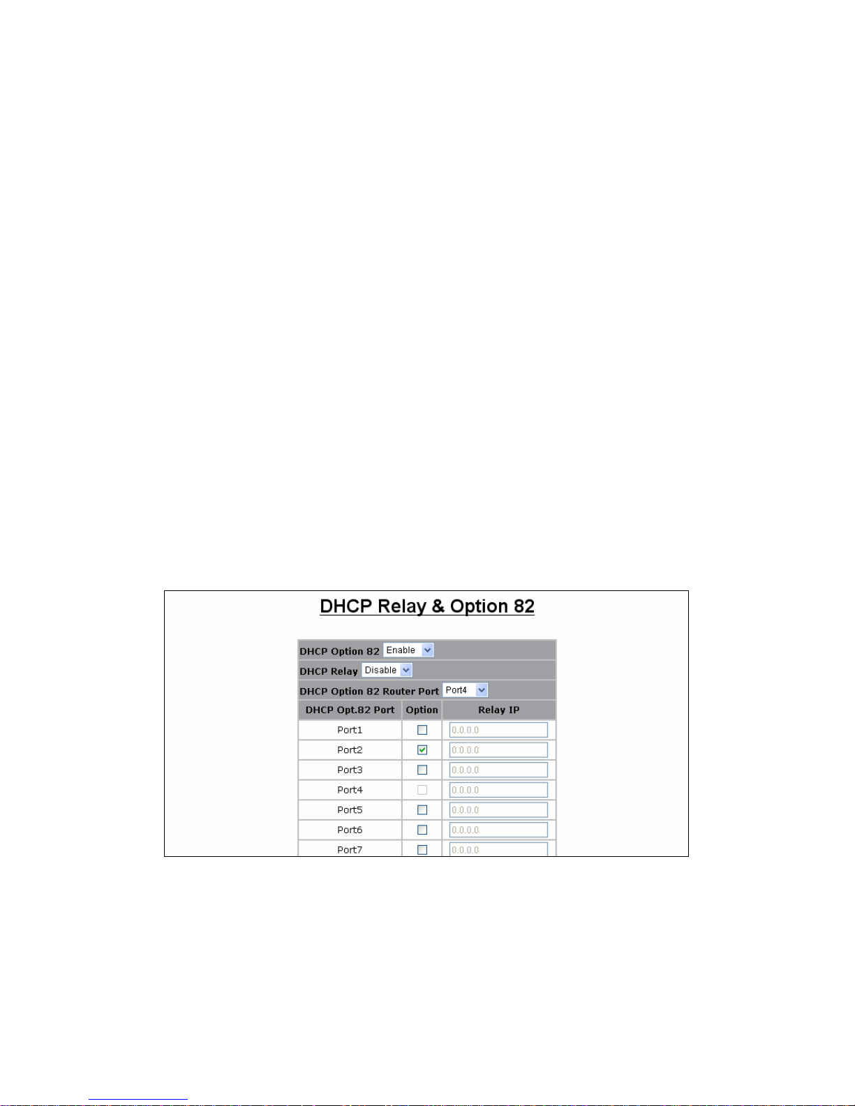
3.2.3.6 DHCP Relay and Option 82
The Relay Agent Information option (Option82) is inserted by the DHCP relay
agent when forwarding client-originated DHCP packets to a DHCP server
(RFC 3046). Servers recognizing the Relay Agent Information option may use
the information to implement IP address or other parameter assignment
policies. The DHCP Relay can forward the DHCP broadcast packets to a
DHCP server in a different subnet (RFC 1542). So DHCP server can provide
IP addresses to clients spanning multiple subnets instead of deploying a
DHCP server on every subnet.
3.2.3.7 LLDP
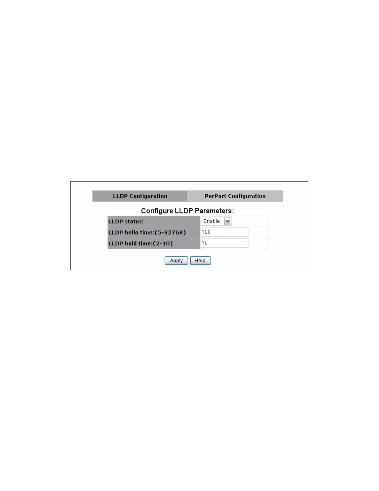
LLDP Configuration
Link Layer Discovery Protocol (LLDP) operates on data link layer. It stores and
maintains the information about the local device and the devices directly
connected to it for network administrators to manage networks through NMS
(network management systems).In LLDP, device information is encapsulated
in LLDP PDUs in the form of TLV (meaning type, length, and value) triplets and
-39-
Page 40
is exchanged between directly connected devices. Information in LLDP PDUs
received is restored in its MIB. A LLDP-enabled device operating in the TxRx
mode or Tx mode sends LLDP PDUs to its directly connected devices
periodically. It also sends LLDP PDUs when the local configuration changes to
inform the neighboring devices of the change timely. In any of the two cases,
an interval exists between two successive operations of sending LLDP PDUs.
This prevents the network from being overwhelmed by LLDP PDUs even if the
LLDP operating mode changes frequently. To enable the neighboring devices
to be informed of the existence of a device or an LLDP operating mode change
(from the disable mode to TxRx mode, or from the Rx mode to Tx mode) timely,
a device can invoke the fast sending mechanism. In this case, the interval to
send LLDP PDUs changes to one second. After the device sends specific
number of LLDP PDUs, the interval restores to the normal. An LLDP-enabled
device operating in the TxRx mode or Rx mode validates the TLVs carried in
the LLDP PDUs which receive and store the valid neighboring information. An
LLDP PDU also carries a TTL (time to live) setting with it. The information
about a neighboring device maintained locally ages out when the
corresponding TTL expires.
LLDP Status: Enable/Disable LLDP.
LLDP hello time: LLDP hello time value which is time interval between the
transmission LLDP info packets. Value range is from 5 to 32768. Default value
is 30.
LLDP hold time: LLDP hold time value. Value range is from 2 to 10. Default
value is 4.
-40-
Page 41
PerPort Configuration
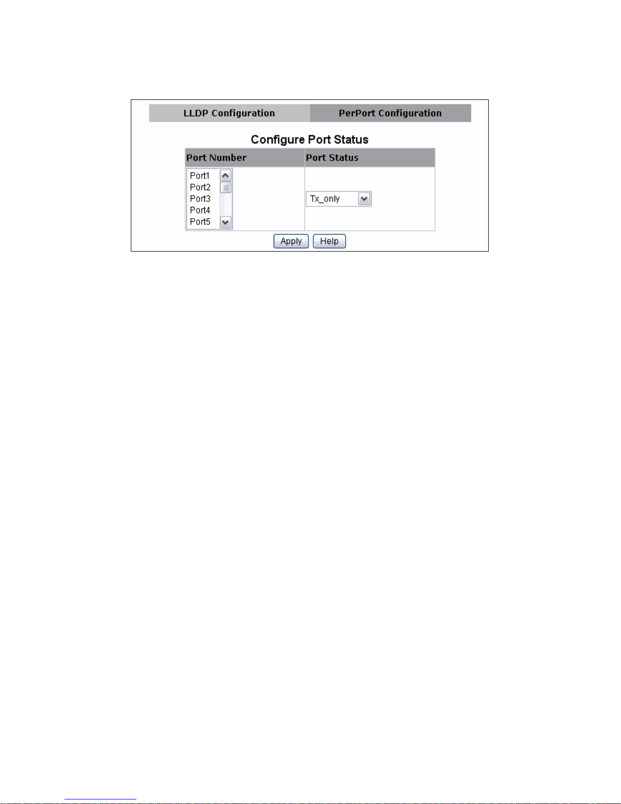
Port Number: specify the port(s) to be configured in the switch.
Port Status: specify one of four port mode to operate LLDP for specified
port(s)
Tx only: LLDP transmit the packet of the port only
Rx only: LLDP receive the packet of the port only.
Tx and Rx: LLDP transmit and receive the packets of the port.
Disable: LLDP do not transmit and receive the packets of the port.
3.2.4. Access Control List
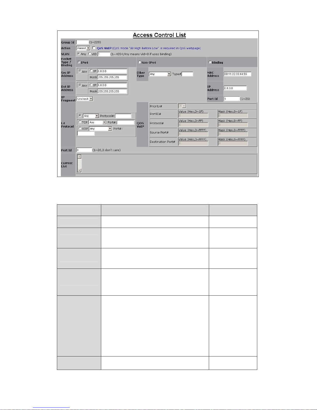
Packets can be forwarded or dropped by ACL rules include IPv4 or non-Ipv4.
VT6530 can be used to block packets by maintaining a table of packet
fragments indexed by source and destination IP address, protocol, and so on.
The web was divided into four domain IPV4, non-IPv4, Binding and QOS VOIP.
Enable/Disable ACL rule: Select an ACL entry which you want to
enable/disable in the Current List. Then click Enable /Disable to execute.
Reset ACL count: Select an ACL entry which you want to reset its counts
(octetcnt and packetcnt fields) in the Current List. Then click Reset Hit Count to
do the action.
-41-
Page 42
3.2.4.1. IPv4
The IPv4 related parameters are shown in the following table
Items Option Default value
Group ID 1 ~ 220 (max. 220 ACL groups) NULL
Permit / Deny.
Action
VLAN
Packet Type
Src
IP Address
Dst
IP Address
Permit: Permit packet cross switch.
Deny: Drop packet.
Any / VID.
Any: Any VLAN ID
VID: 1~4094. A certain VLAN ID.
IPv4 / Non-IPv4 / Binding
IPv4: Set Ipv4 packet field.
Non-IPv4: Set non-IPv4 packet field.
Binding: Set binding entry.
(Set this field if Packet Type is IPv4,
else ignore.)
Any / IP and Mask
Any: Any IP address.
IP: A certain IP address.
Mask: ***.***.***.***
* is represent a digit from 0~9,
*** is range from 0 to 255
Notice: This is not subnet mask.
(Set this field if Packet Type is IPv4,
else ignore.)
Permit
Any
IPv4
Any
Any
-42-
Page 43

IP Fragment
L4 Protocol
Protocol
TCP
Port
UDP
Port
Port Id
Any / IP and Mask
Any: Any IP address.
IP: A certain IP address.
Mask: *** *** *** ***
* is represent a digit from 0~9,
*** is range from 0 to 255
(Set this field if Packet Type is IPv4,
else ignore.)
Uncheck / Check
Uncheck: Not check IP fragment field.
Check: Check IP fragment field.
(Set this field if Packet Type is IPv4,
else ignore.)
Any / ICMP(1) / IGMP(2) / TCP(6) /
UDP(17)
(Set this field if Packet Type is IPv4,
else ignore.)
0~255. If protocol not find in L4 Protocol
field, you can direct assign number.
(Set this field if Packet Type is IPv4,
else ignore.)
Any / FTP(21) / HTTP(80)
(Set this field if Packet Type is IPv4,
else ignore.)
0~65535 If TCP port not find in TCP
field, you can direct assign number.
(Set this field if Packet Type is IPv4,
else ignore.)
Any / DHCP(67) / TFTP(69) /
NetBIOS(137)
(Set this field if Packet Type is IPv4,
else ignore.)
0~65535 If UDP port not find in UDP
field, you can direct assign number.
Source port id, from 1~10, 0 means
don’t care.
Uncheck
Any
NULL
Any
NULL
Any
NULL
0
Current List Create ACL and Binding groups. NULL
The octetcnt is octet number of the
Count
packets hitting the ACL rule.
The packetcnt is the packet number
hitting the ACL rule.
0
-43-
Page 44

3.2.4.2. Non-IPv4
The related parameters are shown in the following table:
Items Option Default value
Group ID 1 ~ 220 (max. 220 ACL group) NULL
Permit / Deny.
Action
VLAN
Packet Type
Ether type
Type
Current List Create ACL and Binding groups. NULL
Permit: Permit packet cross switch.
Deny: Drop packet.
Any / VID.
Any: Any VLAN ID.
VID: 1~4094. A certain VLAN ID.
IPv4 / Non-IPv4 / Binding
IPv4: Set Ipv4 packet field.
Non-IPv4: Set non-IPv4 packet field.
Binding: Set binding entry.
(Set this field if Packet Type is
Non-IPv4, else ignore.)
Any / ARP(0x0806) / IPX(0x8137)
(Set this field if Packet Type is
Non-IPv4, else ignore.) 0~0xFFFF
If ether type not find in Ether Type
field, you can direct assign number.
Permit
Any
IPv4
Any
NULL
3.2.4.3. Binding
Let device that has specific IP address and MAC address can use network. We
can set specific IP address, MAC address, VLAN id and port id to bind, and
device can cross switch if all conditions match. Use binding function; we
should enable it first in following page.
In “Packet Type / Binding” box should select “Binding”.
The related parameters are shown in the following table:
Items Option Default value
Group ID 1 ~ 220 (max. 220 ACL group) NULL
Permit / Deny.
Action
VLAN
Packet Type
Mac Address
Permit: Permit packet cross switch.
Deny: Drop packet.
Any / VID.
Any: Any VLAN ID.
VID: 1~4094. A certain VLAN ID.
IPv4 / Non-IPv4 / Binding
IPv4: Set Ipv4 packet field.
Non-IPv4: Set non-IPv4 packet field.
Binding: Set binding entry.
**:**:**:**:**:**
* is represent a digit from 0-9 and A-F
Permit
Any
IPv4
Any
-44-
Page 45
IP Address
***.***.***.***
*** is range from 0 to 255
0.0.0.0
Port ID Source port id from 1~10 1
Current List Create ACL and binding groups NULL
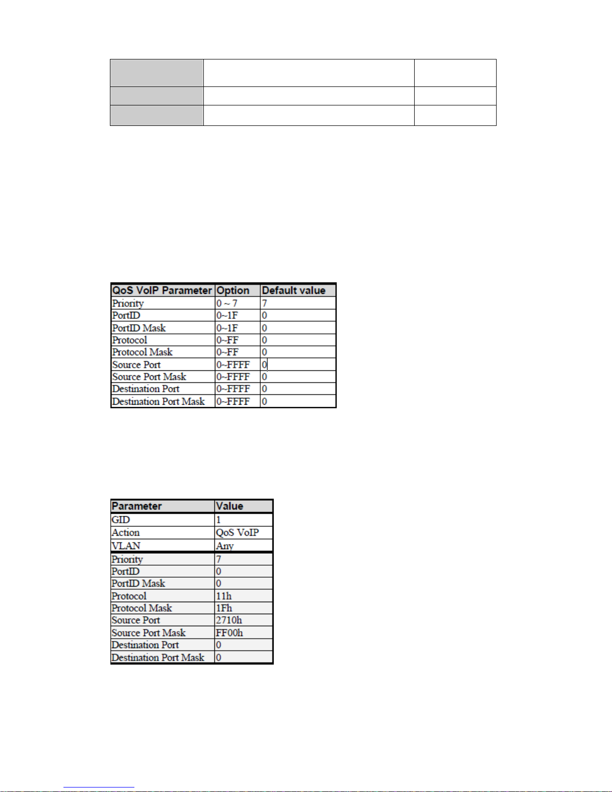
3.2.4.4. QoS VoIP
QoS VoIP option in Action field is to provide ingress VoIP packets can be
forwarded out with higher priority through the ACL function. In “Action” box
select the “QoS VoIP” checkbox to make QoS VoIP parameter area available
to configure.
NOTE: To make this function work, the QoS mode “All High Before Low “ in
QoS Configuration is required.
The QoS VoIP related parameters are shown in the following table:
All parameters with HEX format provide settings in continuous range. For
example, if we want VoIP packets, with UDP protocol type (17) and source port
number is in range of 10000~10015, to be forwarded out with highest priority
while network congestion happens, an ACL rule can be created like the
following setting:
-45-
Page 46
3.2.5. Security
3.2.5.1. Security Manager
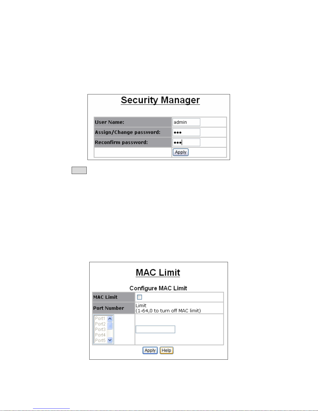
In this page, user can change user name and password with the following
parameters.
User Name: Type the new user name. The maximum length is 10 characters.
Assign/Change password: Type the new password.
Reconfirm password: Retype the new password.
Click Apply to activate the setting.
3.2.5.2. MAC Limit
MAC limit allows users to set a maximum number of MAC addresses to be
stored in the MAC address table. The MAC addresses chosen to be stored in
MAC address table is the result of first-come-first-save policy. Once a MAC
address is stored in the MAC address table, it stays in until it is aged out.
When an “opening” is available, the switch stored the first new MAC address it
sees in that opening. All packets from MAC addresses not in the MAC address
table should be blocked.
MAC Limit: You can enable or disable MAC limit function for all ports.
Limit: The maximum number of per-port MAC addressees to be learned (1-64,
0 to disable this port's MAC limit function).
-46-
Page 47
3.2.5.3. 802.1x Configuration
802.1x makes use of the physical access characteristics of IEEE 802 LAN
infrastructures in order to provide a means of authenticating and authorizing
devices attached to a LAN port that has point-to-point connection
characteristics, and of preventing access to that port in cases in which the
authentication and authorization process fails. In the beginning, 802.1 x
configuration page is disabled because 802.1x is disabled in default. To enable
802.1x, go to Administration-> Switch setting ->Misc Configs page to enable
the 802.1x protocol field. After clicked Apply, the 802.1x configuration page will
be shown up.
3.2.5.3.1 System Configuration
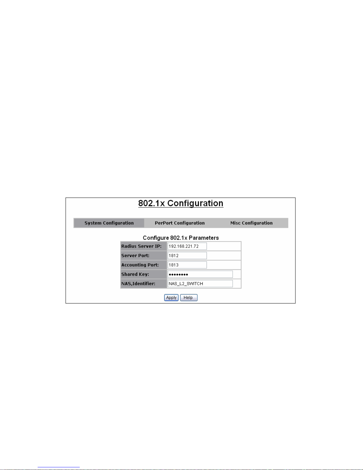
Radius Server IP: The IP address of the authentication server.
Server Port: The UDP port number used by the authentication server to
authenticate (default: 1812).
Accounting Port: The UDP port number used by the authentication server to
retrieve accounting information (default: 1813).
Shared Key: A key shared between this switch and authentication server.
NAS, Identifier: A string used to identify this switch.
3.2.5.3.2 Perport Configuration
You can select the specific port and configure the authorization state. There
are 4 kinds of authorization state to provide for each port.
Fu: Force the specific port to be unauthorized.
Fa: Force the specific port to be authorized.
Au: The state of the specific port was determined by the outcome of the
authentication.
No: The specific port didn't support 802.1x function.
-47-
Page 48
3.2.5.3.3 Misc Configuration
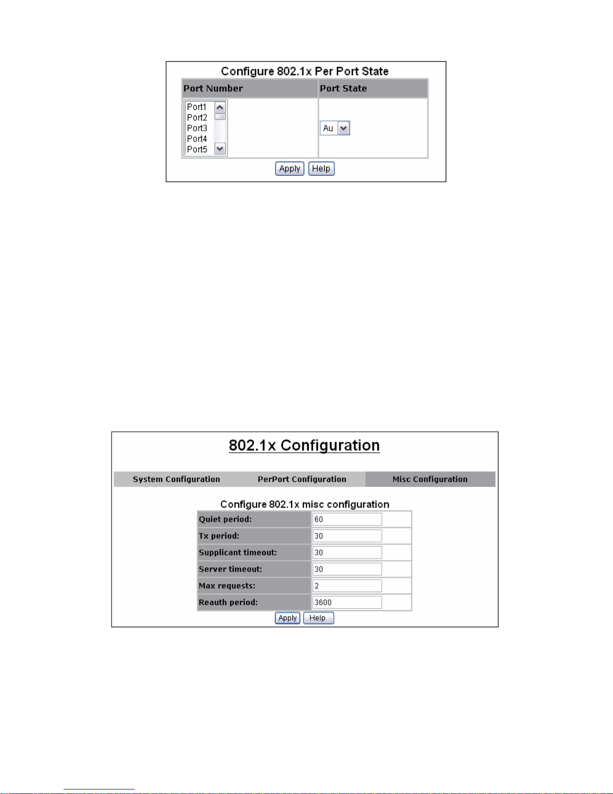
In this page, you can change the default configuration for the 802.1x standard:
Quiet Period: Used to define periods of time during which it will not attempt to
acquire a supplicant (default time: 60 seconds).
Tx Period: Used to determine when an EAPOL PDU is to be transmitted
(Default value is 30 seconds).
Supplicant Timeout: Used to determine timeout conditions in the exchanges
between the supplicant and authentication server (default value: 30 seconds).
Server Timeout: Used to determine timeout conditions in the exchanges
between the authenticator and authentication server (default value: 30
seconds).
Max requests: Used to determine the number of re-authentication attempts
that are permitted before the specific port becomes unauthorized (default
value: 2 times).
Reauth Period: Used to determine a nonzero number of seconds between
periodic re-authentication of the supplications (default value: 3600 seconds).
-48-
Page 49
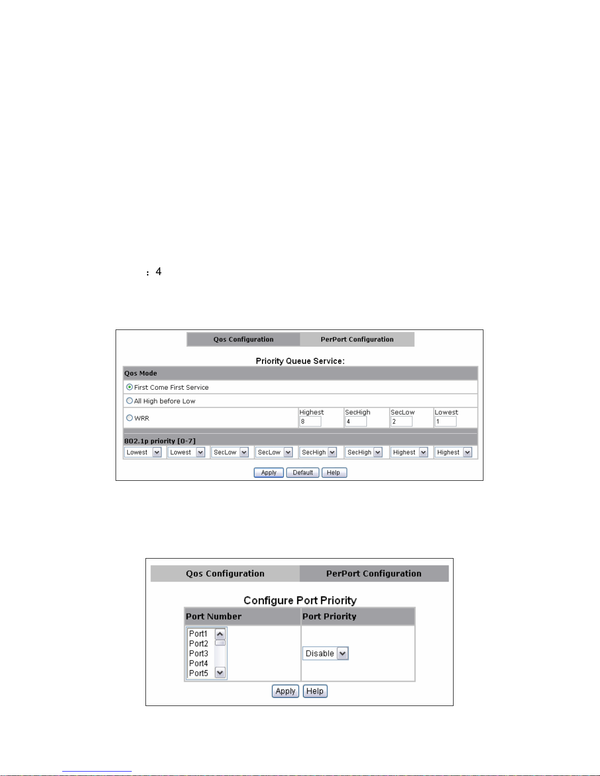
3.2.6. QoS
This switch provides quality of service (QoS) to prioritize the packet forwarding
when traffic congestion happens. This switch supports port-based (4-level
output queue) and 802.1p (8-level priority to 4-level queue mapping)QoS
functions. Strict and weight round robin (WRR) QoS mode are supported.
3.2.6.1. QoS Configuration
This page is mainly to set the QoS mode (First Come First Service, All High
before Low, and WRR) and 8-level priority to 4 –level queue mapping.
First Come First Service: The sequence of packets sent is depending on
arrive orders. This mode can be regarded as QoS is disabled.
All High before Low: The high priority packets sent before low priority
packets.
WRR: Weighted Round Robin. Select the preference given to packets in the
switch's high-priority queue. These options represent the number of higher
priority packets sent before one lower priority packet is sent. For example, 8
Highest:4 second-high means that the switch sends 8 highest-priority packets
before sending 4 second-high priority packets.
QoS Priority: 8-level (0~7) priority can be mapped to 4-level (Highest,
Second-High, Second-Low, Lowest) queue.
3.2.6.2. Per Port Configuration
Per-port priority can be configured and shown in this page.
Port Number: the ports in the switch.
Port Priority: port priority can be disable or 0-7.
-49-
Page 50
3.2.7. Monitoring
3.2.7.1. Port Status
This page provides current status of every port that depends on user’s setting
and the negotiation result.
State: Display port statuses: disable or enable. “Unlink” will be treated as “off”.
Link Status: Down means “No Link”; Up means “Link up”.
Auto Negotiation: Display the auto negotiation mode: auto/force/nway-force.
Speed status: Display 1000Mbps or 100Mbps or 10Mbps speed, port 1-8 are
10/100Mbps, Port 9-10 are 10/100/1000Mbps."
Duplex status: Display full-duplex or half-duplex mode.
Flow Control: Display the flow control state
Full: Display the flow control is enabled or disabled in full mode.
Half: Display the backpressure is enabled or disabled in half mode.
Rate Control: Display the rate control setting.
Ingress: Display the port effective ingress rate of user setting.
Egress: Display the port effective egress rate of user setting.
Port Security: Display the port security is enabled or disabled.
BSF: Display the port broadcast storm filter control is enable or disable.
Jumbo Frame: Display the jumbo frame is supported or not for the port.
NOTE: You can click the Browser’s Refresh button or press <F5> to update to
the latest status.
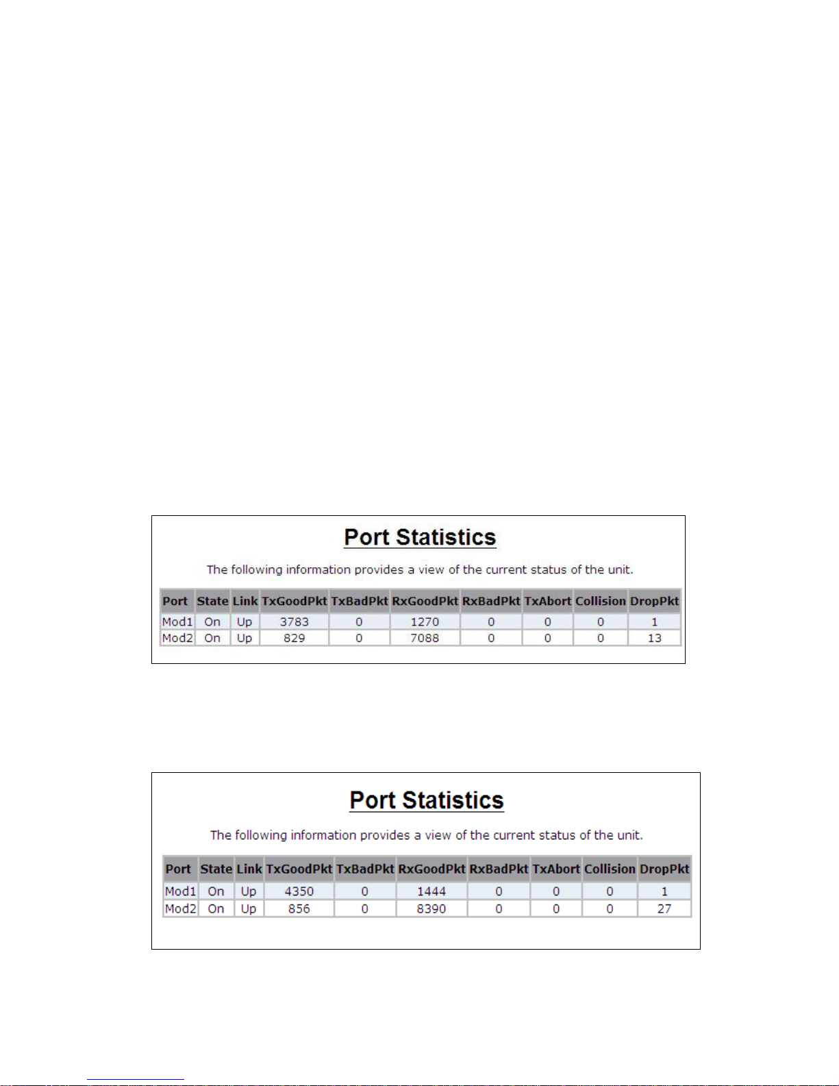
3.2.7.2. Port Statistics
The following information provides a view of the current status of the whole
unit.
Press Reset button to clean all count.
-50-
Page 51
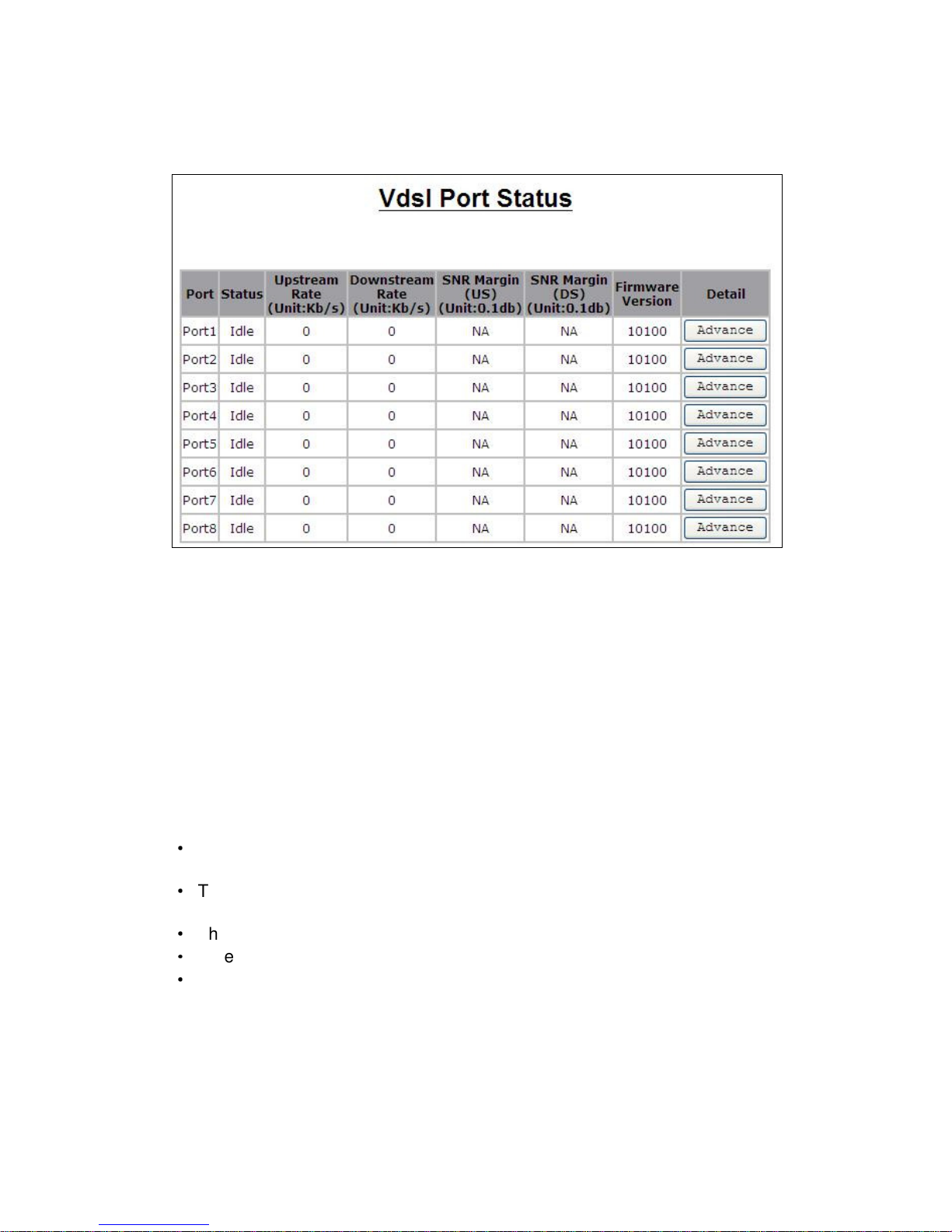
3.2.7.3. Vdsl Port Statistics
This page provides current status of VDSL port’s downstream rate: Upstream
rate, US, DS and VDSL firmware version.
3.2.8. Profile configuration
VDSL2 Profile
ITU-T G.993.2 VDSL2 standard defines a wide range of settings for various
parameters that could potentially be supported by a VDSL2 transceiver.
Profiles are specified to allow transceivers to support a subset of the allowed
settings and still be compliant with this Recommendation. Multiple profiles
allow vendors to limit the complexities of the implementations and develop
implementations that target specific service requirements.
The standard defines 8 VDSL2 profiles (8a, 8b, 8c, 8d, 12a, 12b, 17a, and
30a). VDSL2 transceivers compliant with G.993.2 shall comply with at least
one profile.
Each profile specifies normative values for the following parameters
·
The maximum aggregate transmit power in the downstream and upstream
directions;
·
The minimum aggregate transmit power in the downstream and upstream
directions;
·
The sub-carrier spacing;
·
Whether support of upstream band zero (US0) is required;
·
The minimum bidirectional net data rate capability (MBDC);
In addition to complying with at least one profile, VDSL2 transceivers shall
comply with at least one annex (Annexes A, B and C) specifying spectral
characteristics. Table 2 shows the 8 profiles and Annexes A, B, C.
-51-
Page 52
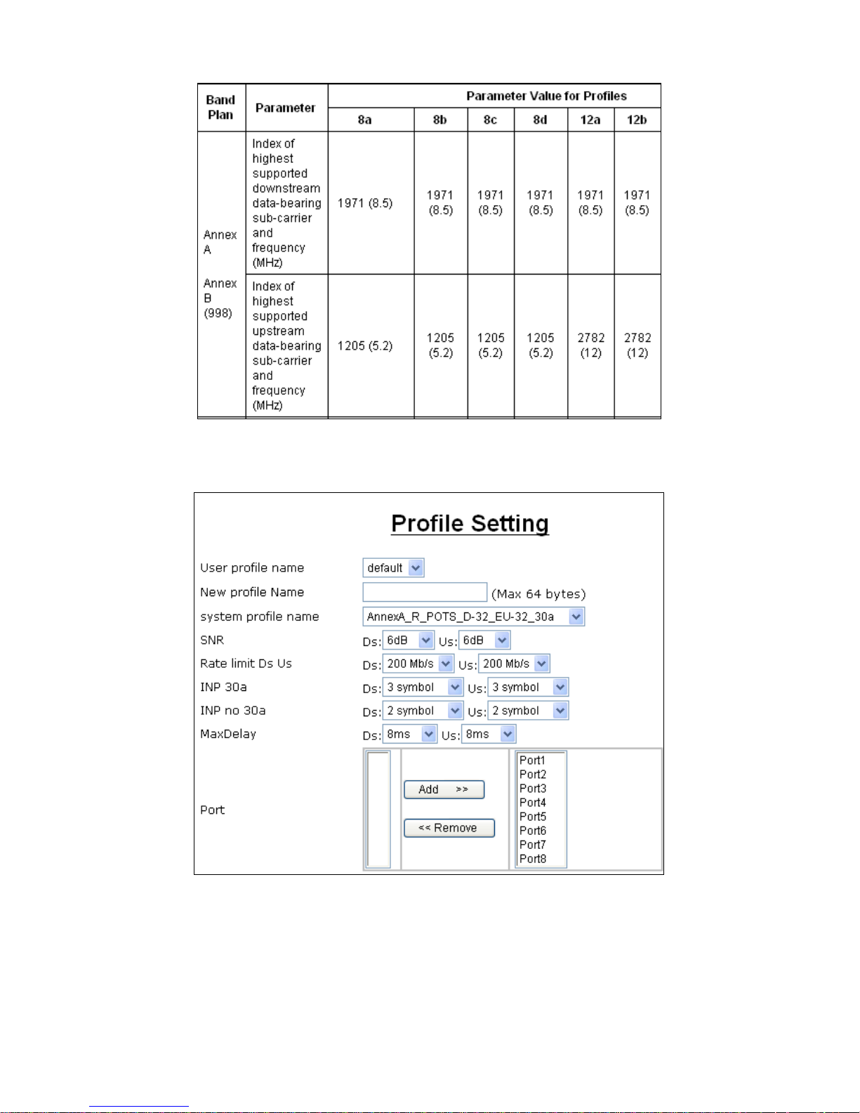
In profile web user can select or create a profile model with the setting of SNR,
INP (Impulse noise protection) and max delay
-52-
Page 53
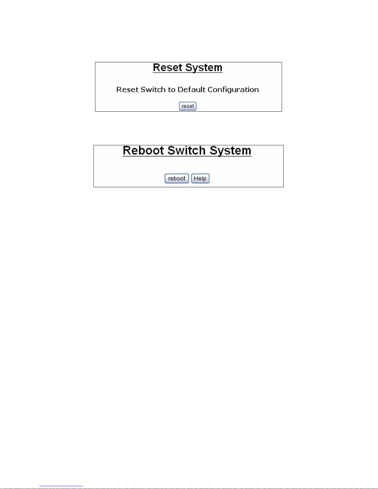
3.2.9. Reset System
The page to reset the switch to default configuration is shown as below.
3.2.10. Reboot
The page to reboot (warm restart) the switch is shown as below.
-53-
Page 54

4. Specifications
4.1. Cable specifications
The related cables specification shown in the following table
Cable Type Cable Requirements Maximum Length
1000BASE-T Category 5e or better, UTP or STP 328 ft (100M)
RJ11 6P4C (six position, four conductor),
Twisted-pair cabling comes in various grades, or categories. Category 5 is
required for Fast Ethernet, and is also the most reliable and most commonly
used category. You can buy UTP Category 5 (Unshielded Twisted Pair)
Ethernet cabling in precrimped lengths, or you can crimp your own. Crimping
your own can result in faulty connections if the
RJ-45 tips are not attached properly. Precrimped Category 5 cabling is
available at most computer retail stores.
The most reliable and commonly used type of Category 5 cabling used is UTP,
or "unshielded twisted pair." STP or "shielded twisted pair" wiring is only
necessary for network environments exposed to excessive amounts of
electromagnetic interference, or EMI. These environments include areas with
high sources of electrical power, air conditioning, generators, and radio signals.
STP is also used for wiring outdoors.
There are two types of the wiring: Straight-Through Cables and Crossover
Cables. Category 5 UTP/STP cable has eight wires inside the sheath. The
wires form four pairs. Straight-Through Cables has same pin outs at both ends
while Crossover Cables has a different pin arrangement at each end.
In a straight-through cable, wires 1,2,3,4,5,6,7 and 8 at one end of the cable
are still wires 1~8 at the other end. In a crossover cable, the wires of 1,2,3,6
are reversed so that wire 1 become 3 at the other end of the cable, 2 becomes
6, and so forth.
To determine which wire is wire 1, hold the RJ-45 cable tip with the spring clip
facing towards the ground and the end pointing away from you. The copper
wires exposed upwards to your view. The first wire on the far left is wire 1. You
can also refer to the illustrations and charts of the internal wiring on the
following page.
There are two types of cables: Straight Through Cables and Crossover Cables.
Category 5 UTP/STP cable has eight wires inside the sheath. The wires form
four pairs. Straight Through Cables has same pin outs at both ends while
Crossover Cables has a different pin arrangement at each end.
Figure 4-1 shows the diagram of Straight Through Cables. Figure 4-2 shows
the diagram of Crossover Cables. Figure 4-3 shows the diagram of RJ-11
100Mbps@984ft
(300M)
-54-
Page 55
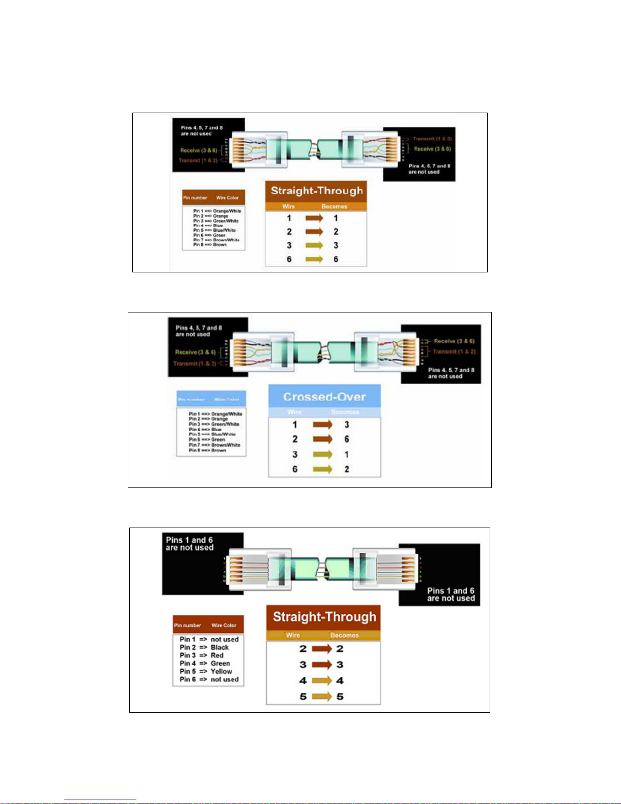
Cables
Figure 4-1: Diagram of Straight Through Cables
Figure 4-2: Diagram of Crossover Cables
Figure 4-3: RJ11 Cable Diagram
-55-
Page 56

4.2. Technical Specifications
4.2.1. Software Specification
Supports 802.1D bridge self-learning, storing up to 8K+ 256unicast or
multicast addresses
Supports automatic age-out period between 1 to 1,000,000 seconds
Broadcast storm filtering based on ingress port bandwidth
HOL blocking prevention
Deadlock relief
9K+ jumbo packets supported on per port and per VLAN basis
Supports layer 2 source filtering
Supports 802.1D Spanning Tree Algorithm and Protocol, and 802.1w Rapid
Reconfiguration
Flexible per-port VLAN classification option supports port-based VLAN
domain and 802.1Q VLAN domain simultaneously
Supports 802.1X Port-based Network Access Control
Supports 802.3ad Aggregation of Multiple Link Segments
Statistical load-balancing algorithm may be configured to be function of
source and destination MAC addresses, ingress port ID, source and
destination IP addresses, and TCP/UDP source and destination ports
Supports BPDU, LACP, EAPOL suppression based on per port
configuration
Supports 64 VLAN-dependent Spanning Trees
Supports IP multicast and snooping of IGMP and IP multicast routing
protocol PDU Including IGMP, CBT, OSPF, and PIM v2
IP multicast packets may be forwarded within single VLAN or across
multiple VLANs. Cross-VLAN mode allows each egress port to have its own
tag rule and VID for IP multicast packets
Supports Port mirroring
Supports 802.1p Traffic Priority
ToS-to-802.1p priority mapping
Supports 802.1p remarking:
The prioritization result can be made available to other switches in the
network by replacing priority field in VLAN tag
Four priority egress queues per port
QoS Scheduling algorithms: strict priority or weighted round robin
Four RMON groups (1,2,3,9)
Supports MIB of RFC1213, 1573, 1757, 1643, 2233
MAC address table synchronization assistance
Asymmetric VLAN membership for better network security:
Distinguish ingress VLAN member and egress VLAN member
Prevents a station to sneak in VLAN set up for common servers, e.g. IPTV
services
Improved VLAN ingress rules may specify:
Filtering untagged packets or VLAN tagged packets
Filtering packets received on non-ingress VLAN member ports
Supports insertion of 2nd tag with programmable TPID to VLAN-tagged
packets
Port-based ingress rate policing and egress rate pacing
-56-
Page 57

Supports Layer 2/3/4 (Layer 2+) classification:
Standard-length IPv4 packets can use layer 2 VLAN-tag ID, IP protocol,
Source IP, Destination IP, TCP/UDP Destination Port and Source Port,
and TCP SYN field for classification
Non-standard or non-IPv4 packets use part of layer 2/3 header for
classification
Up to 256 different classification rules supported
Each classification rule is associated with an action code
Packet and byte counters for all classification rules to record match
statistic.
Supports Layer 2+ based VLAN classification scheme:
IP subnet based and Protocol-based VLAN achievable by means of
layer 2+ classification
May override VID in VLAN-tag
Supports filtering, redirecting, and/or mirroring of packets based on
Layer 2+ classification result
Redirects IPv6 packets to IPv6-capable network devices
SMAC/SIP bindings for IPv4 packets can be implemented
Layer 2+ packet classification result may be used to define packet
priority
Supports protected port, protected port group, and unprotected port group
VID in transmitted packets can be replaced by a fixed VID associated with
the egress port
The VID to be swapped in by egress port can be different than the default
VID for untagged ingress packets
Support remote profile configuration for 8a, 8b, 8c, 8d, 12a, 12b, 17a, 30a.
4.2.2. Hardware specification
Support 8 ports VDSL2 ports and 2 1000TX with 2 shared Mini-GBIC.
Power supply: External Power adapter 36W:12V/3A depends on the design.
Auto-detect 100FX & 1000SX/LX mini-GBIC fiber module on mini-GBIC
ports.
Supports 8 VDSL DMT port with downstream up to 100Mbps and upstream
up to 100Mbps.
Support remote profile configuration for 8a, 8b, 8c, 8d, 12a, 12b, 17a, 30a
VDSL supports Full Complies to ITU-T G.993.2 & G.997.1.
Automatic polarity detection and correction on all RJ-45 ports for automatic
adjustment of wiring errors.
Provides Flow Control mechanism ensures zero packet loss, IEEE802.3x
Flow Control for full-duplex operation and .Back Pressure for half-duplex
operation.
Supports 8K L2 MAC address entries and 3Mbit packet memory. Operation
through-put supports up to 6.55Mpps wired-speed L2 packet forwarding.
Maximum Frame size: 1536KB, 9K Jumbo frame support.
Provides Store-and-Forward switching mechanism.
Provides non-blocking switching performance.
Provides Multicasting, Broadcasting and Flooding control.
Supports packet-filtering and port security.
Supports 802.1q Tagged based VLAN and Double Tagging VLAN.
Four egress queues on all ports.
-57-
Page 58
Support for Strict Priority, Weighted Round-Robin (WRR) scheduling
policies.
Support 802.1d, 802.1w, 802.1s Spanning Tree protocol.
Support IGMP multicast snooping.
Support 802.1x Port-Based Authentication
Traffic classification based on Port#, VLAN priority in VLAN tagging packet,
DS/TOS field in IP packet.
Supports Ingress and Egress Rate Limiting control.
Supports up to 3 Link Aggregation Groups, load sharing among LAG ports
based on MAC address.
Port Mirroring to monitor the traffic of Mirrored ports.
Support hardware monitor to monitor voltage and temperature.
Power supply: Open Frame 36W, 12V/3A
Console port: Male, DTE. Default setting: 115200.8.N.1
4.3. Environments Specification
Operating Temp 0°C to 40°C (32°F to 104°F )
Storage Temp -40°C to 70°C (-40°F to 158°F )
Operating Humidity 20% to 85%, relative humidity, non-condensing
Storage Humidity 20% to 90%, relative humidity, non-condensing
4.4. Standard Conformance
EMC Certification FCC Class A, CE
-58-
Page 59

5. Warranty statement
We provide this limited warranty for it originally purchased the product from us
or its authorized reseller or distributor. We guarantee that equipment is free
from physical defects in workmanship and material under normal use from the
date of original retail purchase of the Hardware. If the product proves defective
during this warranty period, call our Customer Service in order to obtain a
Return Authorization number. Be sure to have a proof of purchase on hand
when calling. Return requests cannot be processed without proof of purchase.
When returning a product, mark the Return Authorization Number clearly on
the package pack and include you original proof of purchase.
In no event shall our liability exceed the price paid for the product from direct,
incidental or consequential damage resulting from the use of the product, its
accompanying software, or its documentation. We make no warranty or
representation, expressed, implied, or statutory, with respect to its products or
the contents or use of this documentation and all accompanying software, and
specifically disclaim its quality, performance, merchantability, or fitness for any
particular purpose. We reserve the right to revise or update its products,
software, or documentation without obligation to notify any individual or entity.
6. Product Support & Contact
If you come across any problems please contact the dealer from where you
purchased your product.
Contact BEC Technologies, Inc.
Worldwide:
http://www.bectechnologies.com
-59-
 Loading...