

Page 1

Last revised: April, 2014
BEC 9800VN
GigaConnect
®
Wireless-N VoIP Active Ethernet
Point-to-Point Fiber Gateway
User Manual
Version release: v1.14
Page 2

TABLE OF CONTENTS
CHAPTER 1: INTRODUCTION ................................... 1
INTRODUCTION TO YOUR ROUTER................................................................ 1
FEATURES & SPECIFICATIONS ...................................................................... 2
HARDWARE SPECIFICATIONS ....................................................................... 5
APPLICATION DIAGRAM ............................................................................ 6
CHAPTER 2: PRODUCT OVERVIEW .......................... 8
IMPORTANT NOTE FOR USING THIS ROUTER .................................................. 8
DEVICE DESCRIPTION ................................................................................ 9
Front Panel LEDs .................................................................................................. 9
Rear Panel Connectors ....................................................................................... 10
CABLING ............................................................................................... 11
CHAPTER 3: BASIC INSTALLATION.......................... 12
NETWORK CONFIGURATION – IPV4 ........................................................... 13
Configuring a PC in Windows 7 (IPv4) ............................................................... 13
Configuring a PC in Windows Vista (IPv4) ......................................................... 15
Configuring a PC in Windows XP (IPv4) ............................................................. 17
Configuring a PC in Windows 2000 (IPv4) ......................................................... 18
Configuring PC in Windows 98/ME ................................................................... 19
Configuring PC in Windows NT4.0 ..................................................................... 20
NETWORK CONFIGURATION – IPV6 ........................................................... 21
Configuring a PC in Windows 7 (IPv6) ............................................................... 21
Configuring a PC in Windows Vista (IPv6) ......................................................... 23
Configuring a PC in Windows XP (IPv6) ............................................................. 25
DEFAULT SETTINGS ................................................................................. 26
INFORMATION FROM YOUR ISP ................................................................ 27
CHAPTER 4: DEVICE CONFIGURATION ................... 28
Page 3

LOGIN TO YOUR DEVICE ........................................................................... 28
STATUS ................................................................................................ 30
Device Info ......................................................................................................... 31
System Log ......................................................................................................... 33
Statistics ............................................................................................................. 34
DHCP Table ......................................................................................................... 38
ARP Table ........................................................................................................... 38
Wireless ARP Table............................................................................................. 38
Disk Status .......................................................................................................... 39
VoIP Status ......................................................................................................... 39
QUICK START ........................................................................................ 40
CONFIGURATION .................................................................................... 43
Interface Setup ................................................................................................... 43
Internet ........................................................................................................................ 44
LAN............................................................................................................................... 52
Wireless ........................................................................................................................ 56
Wireless MAC Filter ...................................................................................................... 66
Dual WAN ........................................................................................................... 67
Advanced Setup ................................................................................................. 69
Firewall......................................................................................................................... 70
Routing ......................................................................................................................... 71
NAT ............................................................................................................................... 72
Static DNS..................................................................................................................... 77
QoS ............................................................................................................................... 78
Interface Grouping ....................................................................................................... 81
Port Isolation ................................................................................................................ 84
Time Schedule .............................................................................................................. 85
VoIP .................................................................................................................... 86
Basic ............................................................................................................................. 86
Media ........................................................................................................................... 88
Advanced...................................................................................................................... 89
Speed Dial .................................................................................................................... 90
Call Features ................................................................................................................. 91
Access Management .......................................................................................... 94
Device Management .................................................................................................... 94
SNMP ........................................................................................................................... 95
Universal Plug & Play ................................................................................................... 96
Dynamic DNS ................................................................................................................ 97
Access Control .............................................................................................................. 99
Packet Filter ................................................................................................................ 101
Page 4

CWMP (TR-069) .......................................................................................................... 105
Parental Control ......................................................................................................... 107
SAMBA & FTP Server .................................................................................................. 108
Maintenance .................................................................................................... 111
User Management ..................................................................................................... 111
Time Zone ................................................................................................................... 114
License ........................................................................................................................ 115
Firmware & Configuration .......................................................................................... 115
System Restart ............................................................................................................ 117
Diagnostics Tool.......................................................................................................... 118
CHAPTER 5: TROUBLESHOOTING ........................ 120
Problems with the Router ............................................................................... 120
Problem with LAN Interface ............................................................................ 120
Recovery Procedures ....................................................................................... 121
APPENDIX: PRODUCT SUPPORT & CONTACT ....... 122
Page 5

Introduction
1
BEC 9800VN User Manual
CHAPTER 1: INTRODUCTION
Introduction to your Router
Congratulations on your purchase of the BEC 9800VN (Wireless-N VoIP Active Ethernet
Point-to-Point Fiber Gateway). This gateway provides ultra-fast connectivity (FTTP/FTTH) – with
uniquely Small Form Factor Pluggable (SFP) interface that can support 100Base or 1000Base
connectivity in a box. With WAN throughput in excess of 900Mbps and one USB ports on the rear of
the router will support 3G/4G LTE services from selected dongles for high-speed mobile
connectivity. Failover between fixed line and mobile connectivity also quickly and smoothly ensures
maximum Internet uptime. The BEC 9800VN is designed for home and office environment extending
reliable, high-speed, and long-reach last-mile connectivity to people living and working building.
With an integrated 802.11n wireless access point and 4-port Gigabit Ethernet LAN ports, the gateway
enables faster wireless speeds of up to 300Mbps and LAN connection 10 times faster than regular
10/100Mpbs Ethernet LAN. The BEC 9800VN provides a unique Management Center, enabling users
to monitor 3G/4G LTE signal strength, bandwidth, download speed, and much more.
Furthermore, the BEC 9800VN supports remote management which facilitate FTTH service provider
deliver more efficient management. The gateway leverages the extraordinary bandwidth to deliver
high-speed Internet applications to home and office users. The full-featured fibre router providing is an
ideal solution for FTTH deployments.
FTTH Applications
The BEC 9800VN can be used for a point-to-point fibre access network. Since the Fibre WAN
interface allows faster rates over even longer distances, it can support Telcom operators or ISPs to
provide high quality and reliable Internet broadband services to either business users or home users.
The 4-port Gigabit Switch incorporated into the BEC 9800VN enables blistering LAN transfer rates for
multimedia applications such as interactive gaming, IPTV video streaming and real-time audio.
Wireless Mobility and Security
With an integrated 802.11n Wireless Access Point, this router delivers up to 3 times the wireless
coverage of a 802.11b/g network device, so that wireless access is available everywhere in the house
or office. If your network requires wider coverage, the built-in Wireless Distribution System (WDS)
allows you to expand your wireless network without additional wires or cables. BEC 9800VN also
supports the Wi-Fi Protected Setup (WPS) standard and allows users to establish a secure wireless
network just by pressing a button. Multiple SSIDs allow users to access different networks through a
single access point. Network managers can assign different policies and functions for each SSID,
increasing the flexibility and efficiency of the network infrastructure.
IPv6 Supported
Internet Protocol version 6 (IPv6) is a version of the Internet Protocol that is designed to succeed IPv4.
IPv6 has a vastly larger address space than IPv4. The router is already supporting IPv6, you can use
it in IPv6 environment no need to change device. The dual-stack protocol implementation in an
operating system is a fundamental IPv4-to-IPv6 transition technology. It implements IPv4 and IPv6
Page 6

Introduction
2
BEC 9800VN User Manual
protocol stacks either independently or in a hybrid form. The hybrid form is commonly implemented in
modern operating systems supporting IPv6.
Quick Start Wizard
Support a WEB GUI page to install this device quickly. With this wizard, simple steps will get you
connected to the Internet immediately.
Firmware Upgradeable
Device can be upgraded to the latest firmware through the WEB based GUI.
Features & Specifications
• WAN Interface supports up to 1000Mbps downstream and upstream wire-speed (over 900Mbps)
rates
• Dual WAN ports (SFP Cage & Ethernet WAN)
• SFP interface supports 100Base or 1000Base fibre connectivity
•
Extra Rj-45 EWAN WAN port for connecting to ADSL/VDSL/Cable/Fibre modem devices
• 4-port Gigabit LAN Switch
• IPv6 ready (IPv4/IPv6 dual stacks)
• Auto failover feature to ensure an always-on WAN connectivity
• 802.11 wireless AP with high-speed wireless connection rate of up to 300Mbps
• Support Wi-Fi Protecyed Setup (WPS) and WPA-PSK/WPA2-PSK
• Multiple wireless SSIDs with wireless guest access and client isolation
•
Wi-Fi Protected Access (WPA-PSK/ WPA2-PSK) and Wired Equivalent Privacy (WEP)
• Two FXS ports for connecting to regular telephones
• Supports FAX Transmission: T.38 fax relay, G.711 pass-through
• QoS for traffic prioritization and bandwidth management
Network Protocols and Features
•
IPv4, IPv6, IPv4 / IPv6 dual stack
•
NAT,PAT, static(v4/v6) routing and RIP-1/2
•
IPv6 stateless / stateful address auto-configuration
•
IPv6 router advertisement
•
IPv6 over PPP
•
DHCPv6
•
Universal Plug and Play (UPnP) compliant
Page 7

Introduction
3
BEC 9800VN User Manual
•
SNTP, DNS relay, Dynamic Domain Name System(DDNS)
•
Virtual server and DMZ
•
IGMP proxy and IGMP snooping for video service
•
MLD proxy and MLD snooping for video service
•
Management based-on HTTP, port number and IP address
•
Supports Port-based Virtual LAN (VLAN)
•
File sharing with SMB (Samba) and FTP
•
Diagnostic tool
Firewall
•
Built-in NAT Firewall
•
Stateful Packet Inspection (SPI)
• DoS attack prevention including Land Attack, Ping of Death, etc
• Access control
• IP / MAC address / URL / Application Filtering
• Password protection for system management
• Parental Control
• VPN pass-through
Quality of Service Control
•
Traffic prioritization management based-on Protocol, Port Number and IP Address (IPv4/ IPv6)
•
Supports the DiffServ approach
•
Traffic bandwidth control, DSCP marking, and 802.1p marking based-on IP protocol, port
number and IP address
•
Supports 802.1p/q
•
Supports 802.1ad (Q-in-Q)
Wireless LAN
•
Compliant with IEEE 802.11 b/ g/ n standards
• Backward compatible with IEEE 802.11b and 802.11g standards
•
2.4 GHz - 2.484GHz frequency range
•
Up to 300 Mbps wireless operation rate
•
WPS (Wi-Fi Protected Setup) for easy setup
• On / Off Wireless with WPS push button
•
64 / 128 bits WEP supported for encryption
Page 8

Introduction
4
BEC 9800VN User Manual
•
Wireless Security with WPA-PSK, WPA2-PSK, and Mixed WPA / WPA2-PSK support
•
WDS repeater function support
• Multiple SSID
•
Wireless MAC filtering
USB Application Server
•
Storage/NAS: Samba server, FTP Server
VoIP
•
Compliant with SIP standard (RFC3261)
•
Supports G.711 A/μ-Law, G.726, G.729 audio codec standards
•
Supports telephony features: call waiting, caller ID (DTMF, FSK), speed dial, return call,
anonymous call, distinctive ring, Do Not Disturb, three-way conference, volume control, notify for
voicemail, Call Detailed Records(CDR)
•
Supports voice enhance features: Adaptive jitter buffer, Comfort Noise Generation (CNG),
Silence Suppression (VDA), G.168 Echo Cancellation, Packet Loss Concealment
•
DTMF Method: Inband, RFC 2833, SIP Info
•
FAX Transmission: T.38, G.711 pass-through
•
Voice over data, QoS control to ensure higher voice quality
Management
• Quick Installation wizard
•
Web-based GUI for remote and local management
•
Firmware upgrades and configuration data upload and download via web-based GUI
•
Supports DHCP server / client / relay
• Supports
SNMP v1, v2, v3, MIB-I and MIB-II
•
TR-069 supports remote management
• System log monitoring
• User Access Management Levels
Page 9

Introduction
5
BEC 9800VN User Manual
Hardware Specifications
Physical interface
•
Wireless Antenna: two (2) detachable antennas
•
1-port Gigabit EWAN (Ethernet WAN)
•
1-port 100/1000BASE SFP Cage (WAN)
•
4-port Gigabit auto-crossover (MDI/MDI-X) Gigabit LAN Ethernet ports
•
PoE-PD on Ethernet LAN Port 4
•
VoIP: Two (2) RJ-11 FXS interface ports
•
USB 2.0 for storage service
•
Reset Button
•
Wireless On/Off / WPS Push Button
•
Power Jack
•
Power On/Off Switch
Physical Specifications
• Dimensions (W*H*D): 9.04" x 6.10" x 1.27"(229.5mm x 155mm x 32.24mm)
Page 10
Introduction
6
BEC 9800VN User Manual
Application Diagram
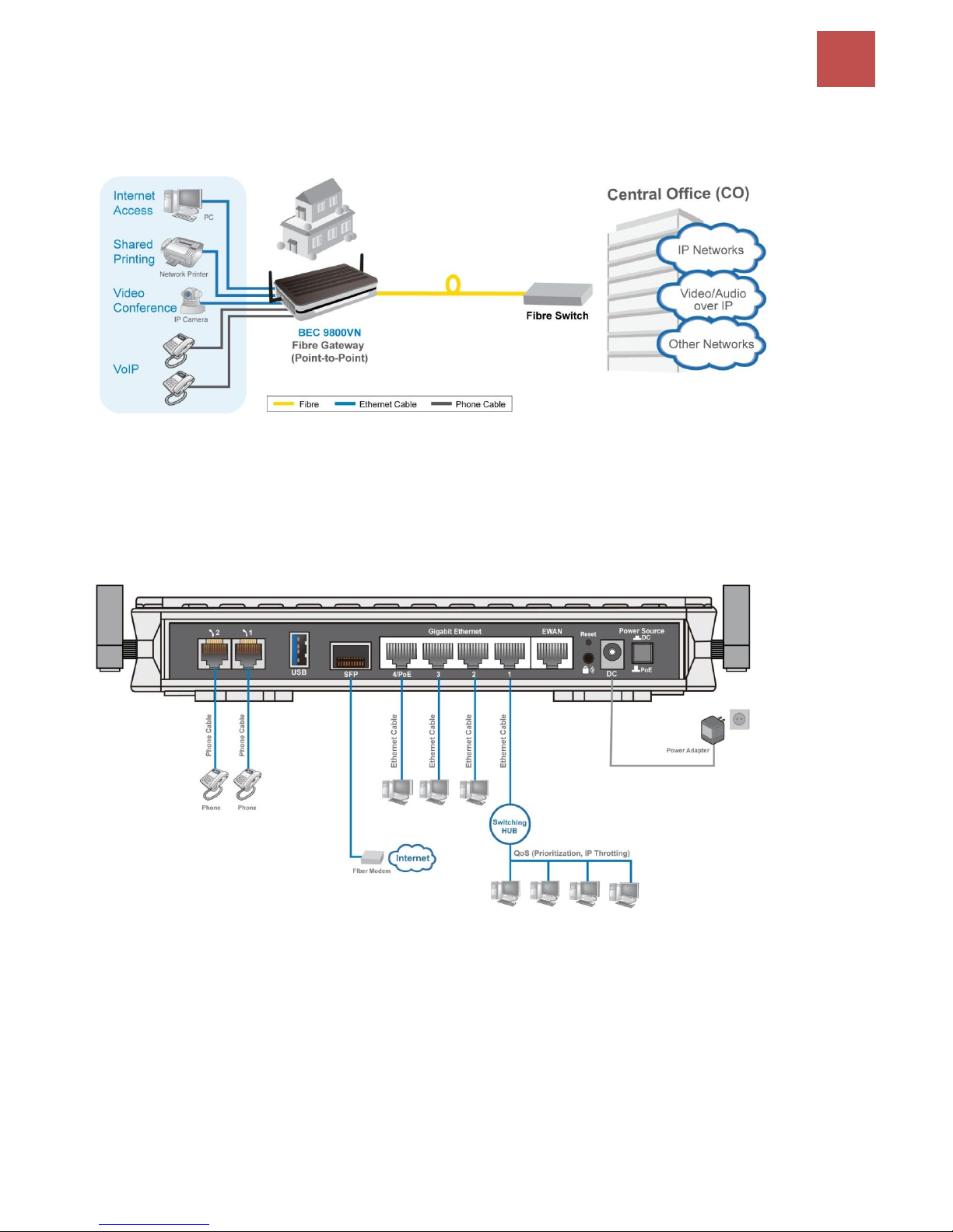
SFP (direct connection to fiber) mode
BEC 9800VN has a SFP interface for direct fibre connection.
Page 11
Introduction
7
BEC 9800VN User Manual
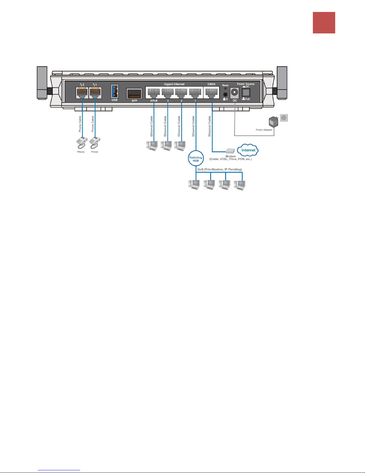
Broadband router mode
BEC 9800VN has a Gigabits Ethernet WAN port to connect to your Fibre/ Cable/ xDSL modem.
Page 12
Basic Installation
8
BEC 9800VN User Manual
CHAPTER 2: PRODUCT OVERVIEW
Important Note for Using This Router
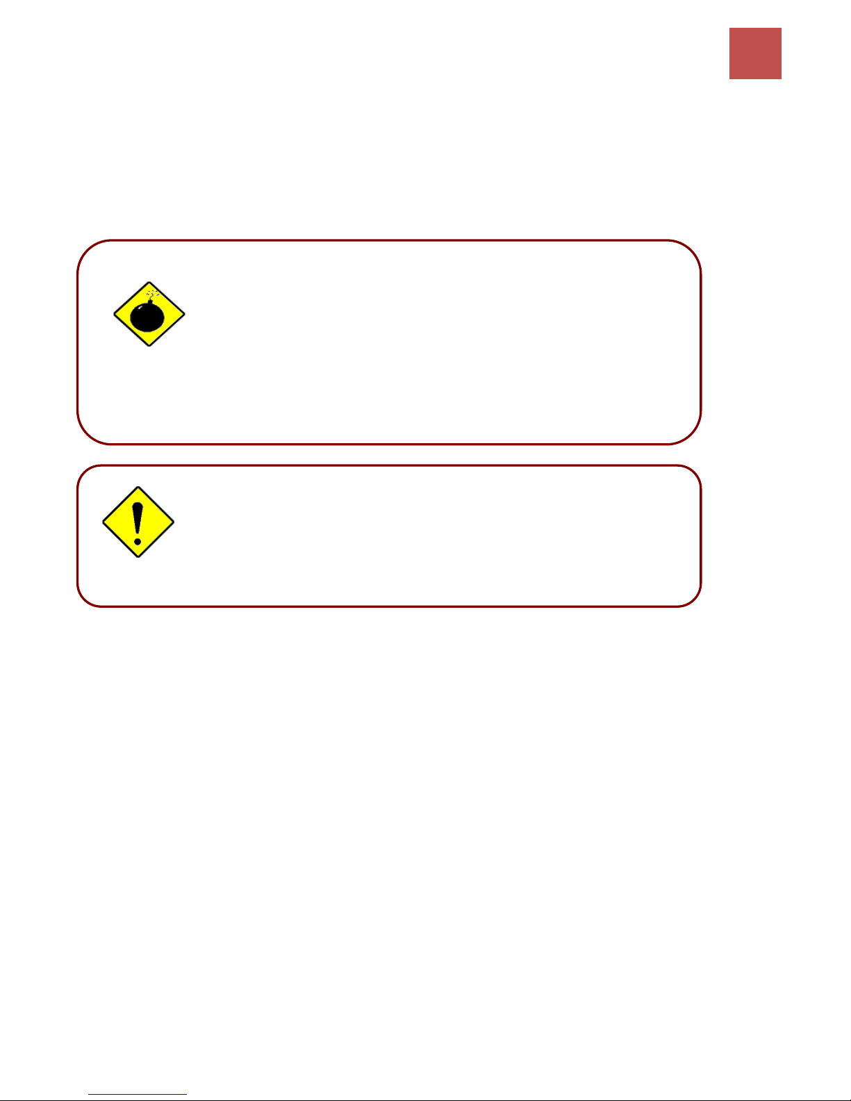
Place the router on a stable surface.
Only use the power adapter that comes with the package. Using
a different voltage rating power adaptor may damage the router.
Attention
Do not use the router in high humidity or high temperature.
Do not use the same power source for the BEC 9800VN on
other equipment.
Do not open or repair the case yourself. If the device becomes
too hot, turn off the power immediately and have it repaired at
a qualified service center.
Avoid using this product and all accessories outdoors.
Warning
Page 13
Basic Installation
9
BEC 9800VN User Manual
Device Description
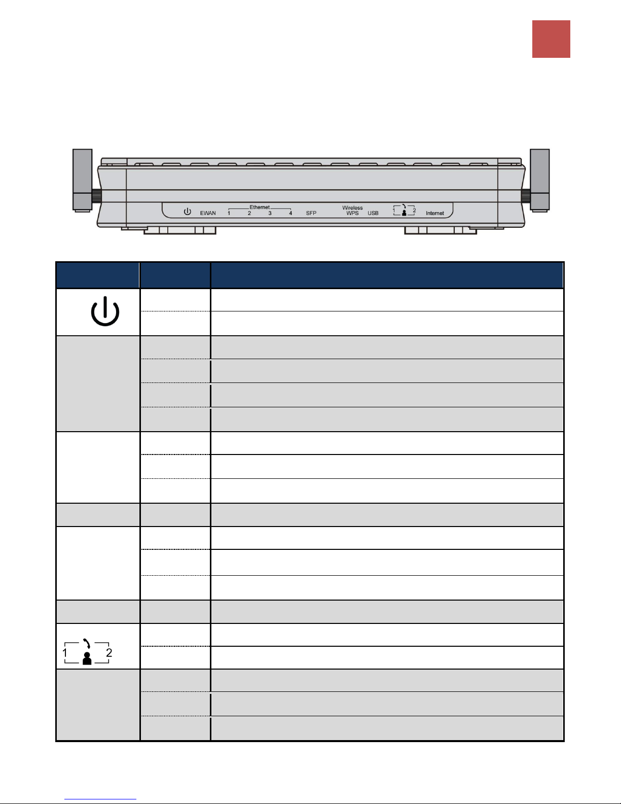
Front Panel LEDs
LED
STATUS
DESCRIPTION
Power
Green
System is up and ready
Red
Boot failure
EWAN
Lit up
BEC 9800VN is successfully connected with a broadband connection device.
Green
Transmission speed is at Gigabit speed (1000Mbps)
Orange
Transmission speed is at 10/100Mbps
Blinking
Data being transmitted/received
Ethernet
Port 1-4
Green
Transmission speed is at Gigabit speed (1000Mbps)
Orange
Transmission speed is at 10/100Mbps
Blinking
Data being transmitted/received
SFP
Green
SFP fiber connection is ready.
Wireless/WPS
Green
Wireless connection established
Green
blinking
Data being transmitted / received
Orange
WPS configuration is in progress
USB
Green
Connecting to a USB dongle or a hard drive.
Phone 1 & 2
Green
Successfully registered and ready to be used.
Orange
Phone is off-hook, in-use
Internet
Green
IP connected and traffic is passing thru the device.
Red
IP request failed.
Off
BEC 9800VN is either in bridged mode or WAN connection not ready.
Page 14
Basic Installation
10
BEC 9800VN User Manual
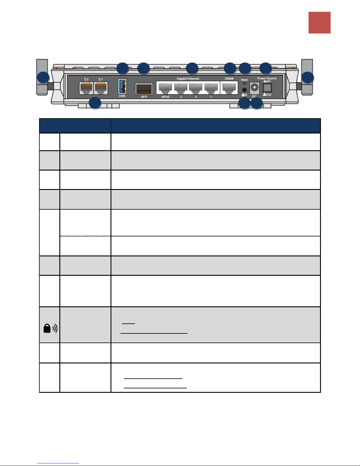
Rear Panel Connectors
PORT
MEANING
1
Antenna
Screw the supplied Wi-Fi antennas onto the antenna connectors on both sides.
2
Phone (1~2)
Connect your analog phone to the phone port with a RJ-11 cable.
3
USB
Connect an external USB dongle / hard drive for storage, network sharing, etc
4
SFP Cage
Insert and gently push the SFP module until it snap into the slot tightly.
Auto-sensing SFP (Small Form Factor Pluggable) transceivers 100Base or
1000Base
5
Gigabit
LAN Ethernet
(1 ~ 4)
Connect a UTP Ethernet cable (Cat-5 or Cat-5e) to one of the four LAN ports when
connecting to a PC or an office/home network of 10Mbps /100Mbps /1000Mbps
4/PoE
LAN Port 4 is also featuring 802.3at PoE PD (Power over Ethernet)
*1
6
Gigabit EWAN
Connect to Fiber/ Cable/ xDSL Modem with a RJ-45 cable
7
Reset
After the device is powered on, press it 6 seconds or above: to restore to factory
default settings (this is used when you cannot login to the router, e.g. forgot your
password)
8
WPS &
Wireless On/Off
By controlling the pressing time, users can achieve two different effects:
(1) WPS
* 2
: Press &hold the button for less than 6 seconds to trigger WPS function.
(2) Wireless ON/OFF button: Press & hold the button for more than 6 seconds to
On/Off the wireless.
9
Power
Connect the supplied Power Adapter to this port.
10
Power Source
Power ON/OFF switch
(1) with Power Switch ON: power up by the supplied DC power adaptor.
(2) with Power Switch OFF: power up by a PoE
* Note:
1. It is required to use a PoE Injector / Device complied with IEEE802.at standard. Using an 802.af standard
PoE device will reduce the performance of BEC 9800VN.
2. For WPS configuration, please refer to the WPS section in the User Manual.
1 2 3 4 5 6 7 8 1
9
10
Page 15

Basic Installation
11
BEC 9800VN User Manual
Cabling
One of the most common causes of problems is bad cabling. Make sure that all connected devices are
turned on. On the front panel of the product is a bank of LEDs. Verify that the LAN Link and LEDs are
lit. If they are not, verify that you are using the proper cables.
Make sure that all other devices (e.g. telephones, fax machines, analogue modems) connected to the
same telephone line as your BEC router have a line filter connected between them and the wall socket
(unless you are using a Central Splitter or Central Filter installed by a qualified and licensed
electrician), and that all line filters are correctly installed in a right way. If the line filter is not correctly
installed and connected, it may cause problems to your connection or may result in frequent
disconnections.
Page 16

Basic Installation
12
BEC 9800VN User Manual
CHAPTER 3: BASIC INSTALLATION
The router can be configured with your web browser. A web browser is included as a standard
application in the following operating systems: Windows 98 / NT /2000 / XP / ME / 7 / Vista, Linux, Mac
OS, etc. The product provides an easy and user-friendly interface for configuration.
PCs must have an Ethernet interface installed properly and be connected to the router either directly
or through an external repeater hub, and have TCP/IP installed and configured to obtain an IP address
through a DHCP server or a fixed IP address that must be in the same subnet as the router. The
default IP address of the router is 192.168.1.254 and the subnet mask is 255.255.255.0 (i.e. any
attached PC must be in the same subnet, and have an IP address in the range of 192.168.1.1 to
192.168.1.253). The best and easiest way is to configure the PC to get an IP address automatically
from the router using DHCP. If you encounter any problems accessing the router’s web interface it
may also be advisable to uninstall any kind of software firewall on your PCs, as they can cause
problems accessing the 192.168.1.254 IP address of the router. Users should make their own
decisions on how to best protect their network.
Please follow the steps below for your PC’s network environment installation. First of all, please check
your PC’s network components. The TCP/IP protocol stack and Ethernet network adapter must be
installed. If not, please refer to your Windows-related or other operating system manuals.
Any TCP/IP capable workstation can be used to communicate with or
through the BEC 9800VN. To configure other types of workstations,
please consult the manufacturer’s documentation.
Page 17
Basic Installation
13
BEC 9800VN User Manual
Network Configuration – IPv4
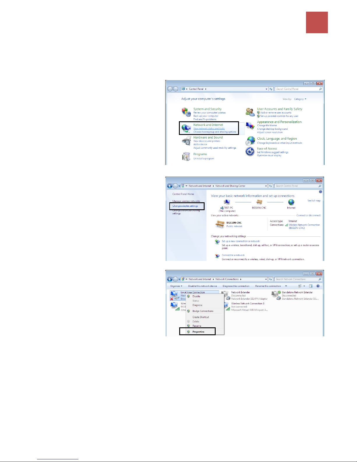
Configuring a PC in Windows 7 (IPv4)
1. Go to Start. Click on Control Panel.
2. Then click on Network and Internet.
3. When the Network and Sharing
Center window pops up, select and
click on Change adapter settings on
the left window panel.
4. Select the Local Area Connection,
and right click the icon to select
Properties.
Page 18
Basic Installation
14
BEC 9800VN User Manual
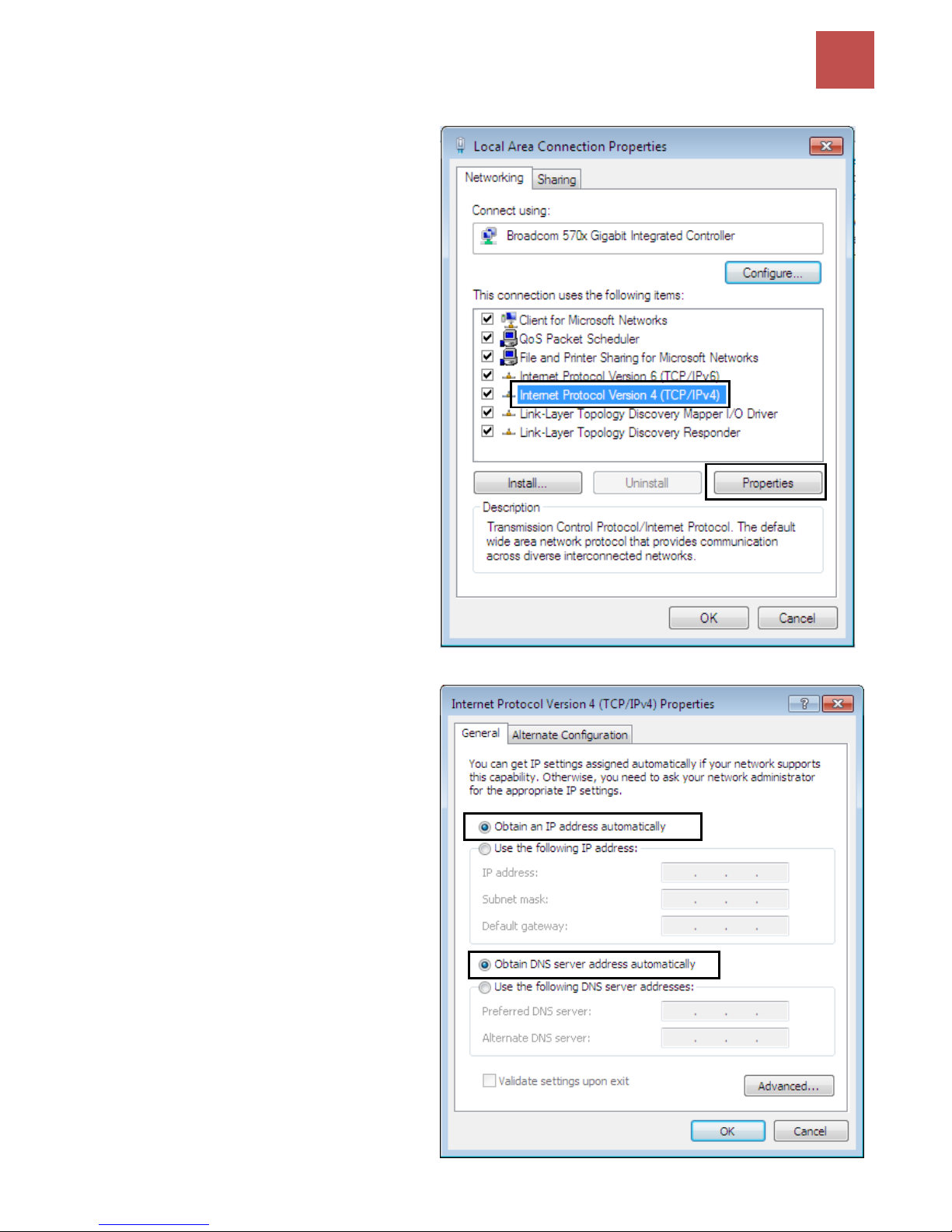
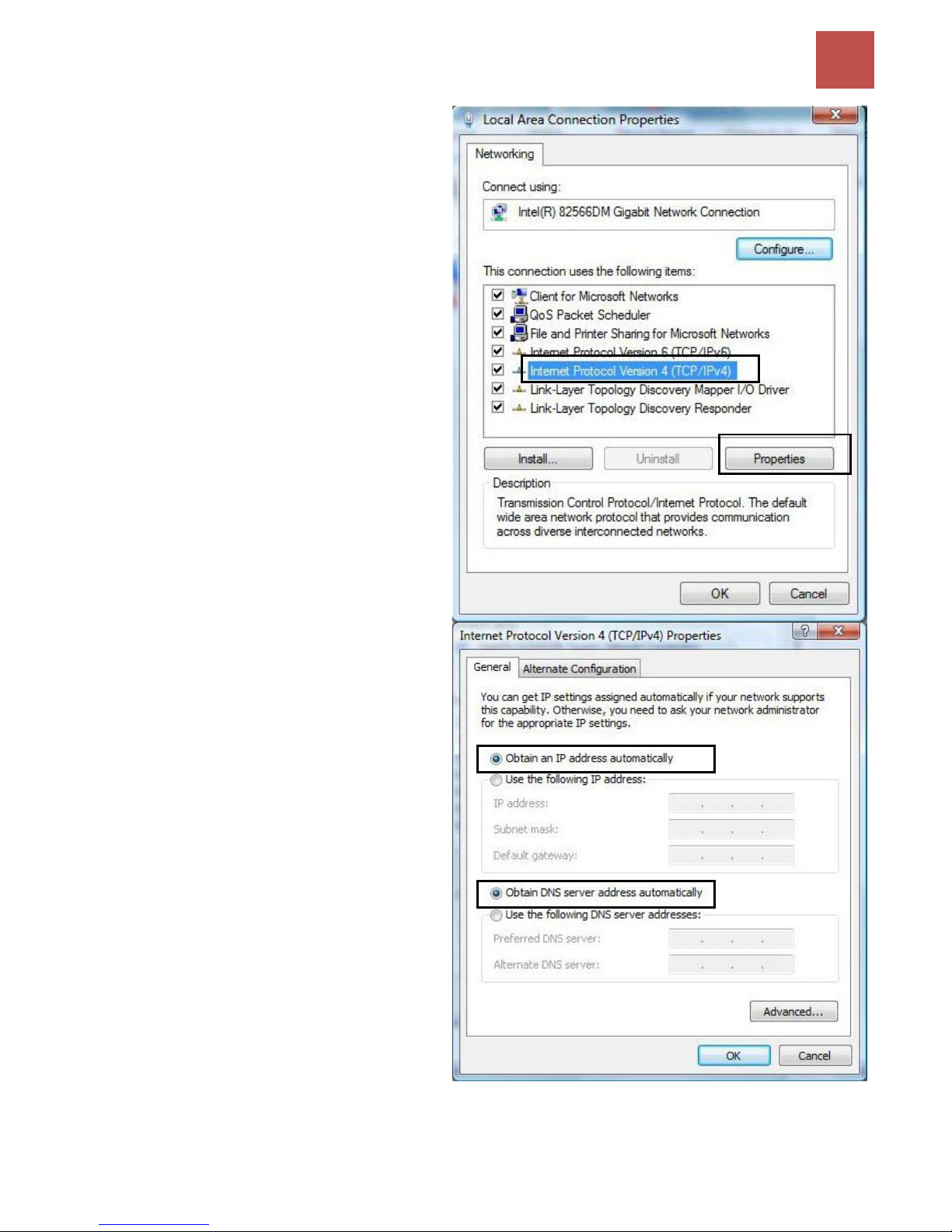
5. Select Internet Protocol Version 4
(TCP/IPv4) then click Properties.
6. In the TCP/IPv4 properties window,
select the Obtain an IP address
automatically and Obtain DNS
Server address automatically radio
buttons. Then click OK to exit the
setting.
7. Click OK again in the Local Area
Connection Properties window to
apply the new configuration.
Page 19
Basic Installation
15
BEC 9800VN User Manual
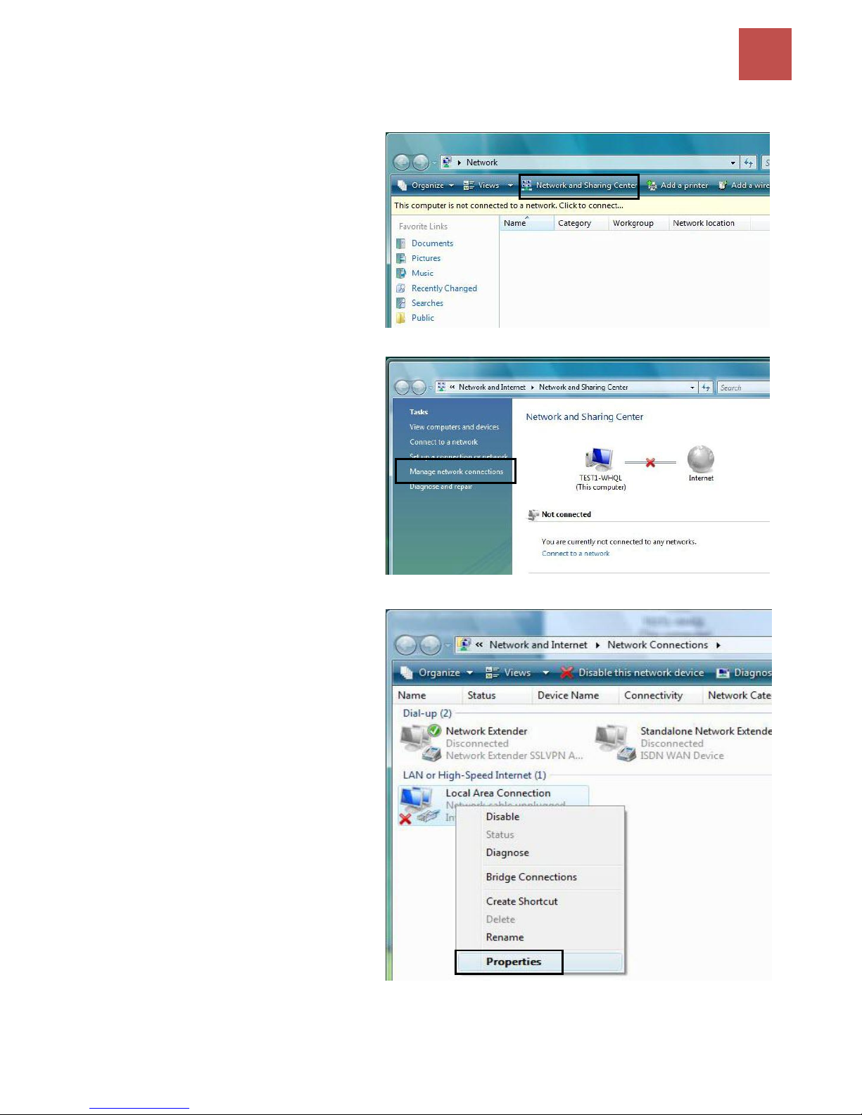
Configuring a PC in Windows Vista (I Pv4)
1. Go to Start. Click on Network.
2. Then click on Network and Sharing
Center at the top bar.
3. When the Network and Sharing
Center window pops up, select and
click on Manage network
connections on the left window
pane.
4. Select the Local Area Connection,
and right click the icon to select
Properties.
Page 20
Basic Installation
16
BEC 9800VN User Manual
5. Select Internet Protocol Version 4
(TCP/IPv4) then click Properties.
6. In the TCP/IPv4 properties window,
select the Obtain an IP address
automatically and Obtain DNS Server
address automatically radio buttons.
Then click OK to exit the setting.
7. Click OK again in the Local Area
Connection Properties window to apply
the new configuration.
Page 21
Basic Installation
17
BEC 9800VN User Manual
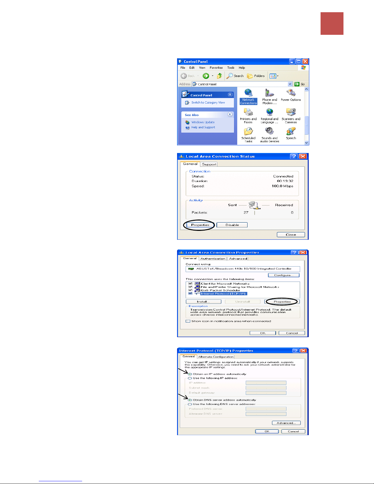
Configuring a PC in Windows XP (IPv4)
1. Go to Start. Click on Control Panel.
2. Then click on Network and Internet.
3. In the Local Area Connection Status
window, click Properties.
4. Select Internet Protocol (TCP/IP) and
click Properties.
5. Select the Obtain an IP address
automatically and the Obtain DNS
server address automatically radio
buttons.
6. Click OK to finish the configuration.
Page 22
Basic Installation
18
BEC 9800VN User Manual
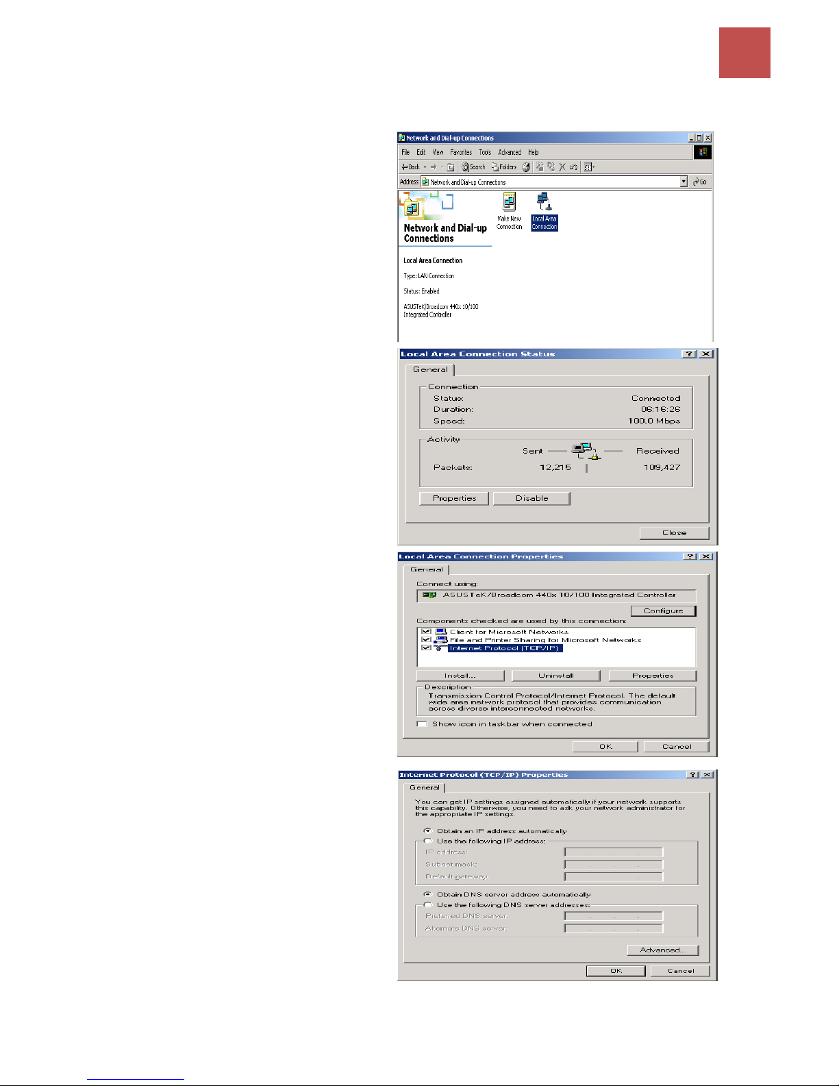
Configuring a PC in Windows 2000 (IPv4)
1. Go to Start / Settings / Control Panel. In
the Control Panel, double-click on Network
and Dial-up Connections.
2. Double-click Local Area Connection.
3. In the Local Area Connection Status
window click Properties.
4. Select Internet Protocol (TCP/IP) and
click Properties.
5. Select the Obtain an IP address
automatically and the Obtain DNS server
address automatically radio buttons.
6. Click OK to finish the configuration.
Page 23
Basic Installation
19
BEC 9800VN User Manual
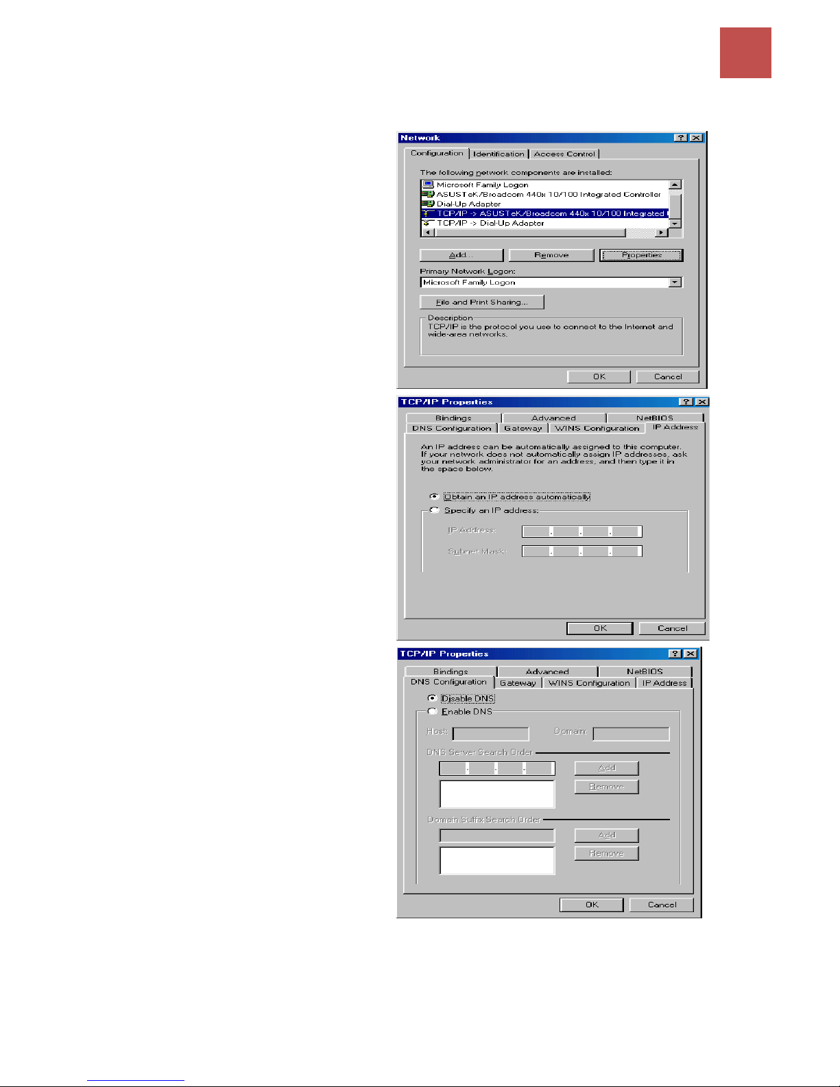
Configuring PC in Windows 98/ME
1. Go to Start / Settings / Control Panel. In
the Control Panel, double-click on Network
and choose the Configuration tab.
2. Select TCP/IP ->NE2000 Compatible, or
the name of your Network Interface Card
(NIC) in your PC.
3. Select the Obtain an IP address
automatically radio button.
4. Then select the DNS Configuration tab.
5. Select the Disable DNS radio button and
click OK to finish the configuration.
Page 24
Basic Installation
20
BEC 9800VN User Manual
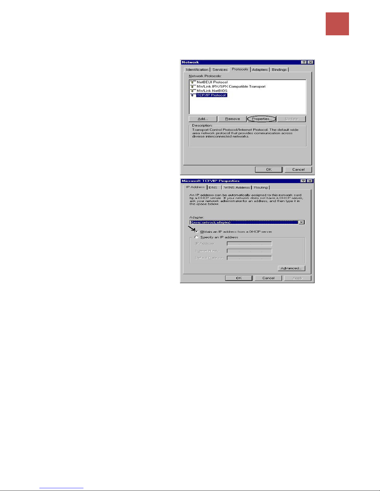
Configuring PC in Windows NT4.0
1. Go to Start / Settings / Control Panel. In
the Control Panel, double-click on Network
and choose the Protocols tab.
2. Select TCP/IP Protocol and click
Properties.
3. Select the Obtain an IP address from a
DHCP server radio button and click OK.
Page 25
Basic Installation
21
BEC 9800VN User Manual
Network Configuration – IPv6
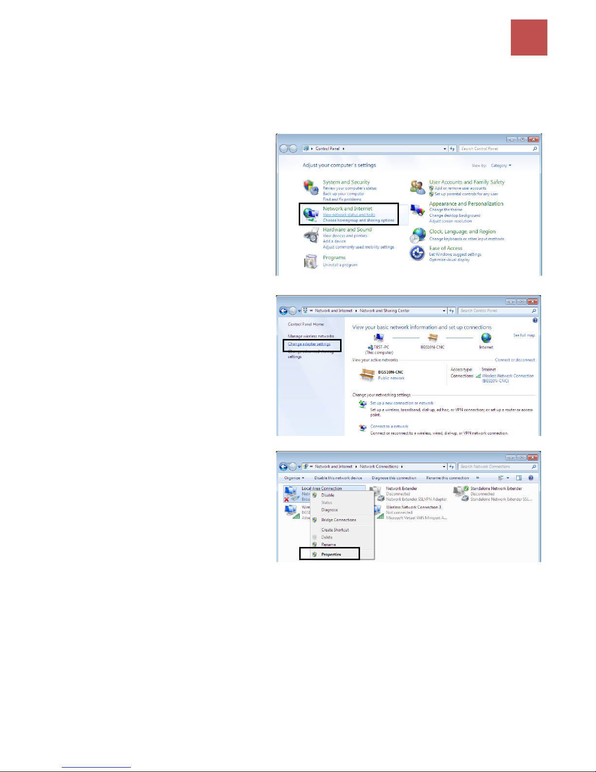
Configuring a PC in Windows 7 (IPv6)
1. Go to Start. Click on Control Panel.
2. Then click on Network and Internet.
3. When the Network and Sharing
Center window pops up, select and
click on Change adapter settings on
the left window panel.
4. Select the Local Area Connection,
and right click the icon to select
Properties.
Page 26
Basic Installation
22
BEC 9800VN User Manual
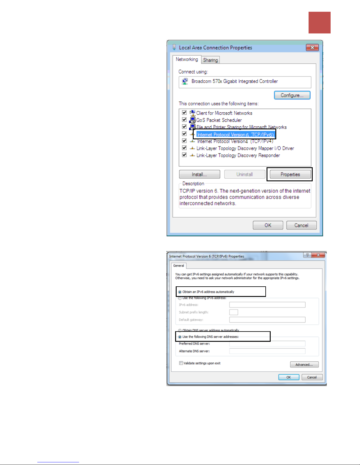
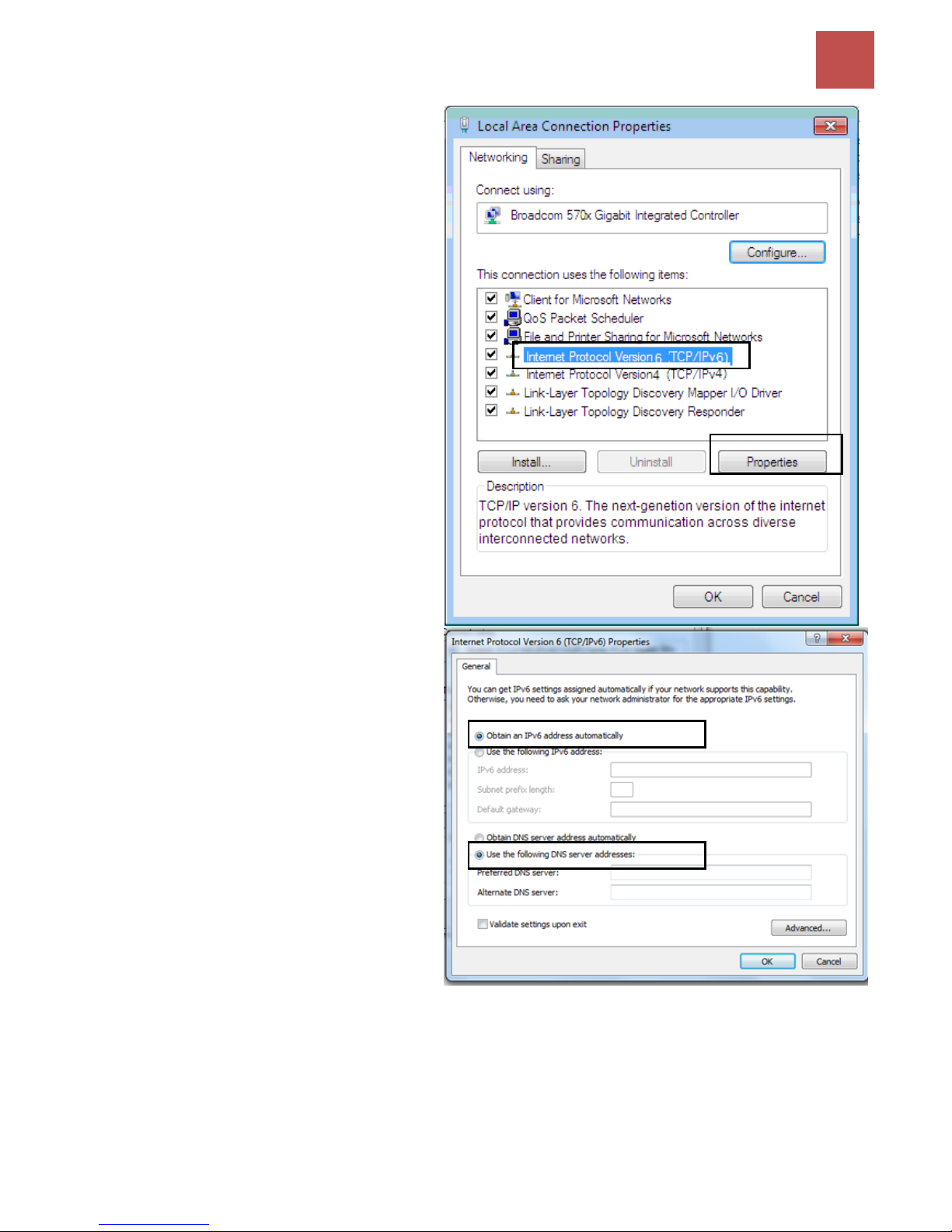
5. Select Internet Protocol Version 6
(TCP/IPv6) then click Properties.
6. In the TCP/IPv6 properties window,
select the Obtain an IPv6 address
automatically and Obtain DNS
Server address automatically radio
buttons. Then click OK to exit the
setting.
7. Click OK again in the Local Area
Connection Properties window to
apply the new configuration.
Page 27
Basic Installation
23
BEC 9800VN User Manual
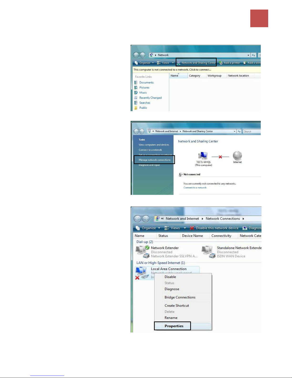
Configuring a PC in Windows Vista (IPv6)
1. Go to Start. Click on Network.
2. Then click on Network and Sharing
Center at the top bar.
3. When the Network and Sharing
Center window pops up, select and
click on Manage network
connections on the left window
pane.
4. Select the Local Area Connection,
and right click the icon to select
Properties.
Page 28
Basic Installation
24
BEC 9800VN User Manual
5. Select Internet Protocol Version 6
(TCP/IPv6) then click Properties.
6. In the TCP/IPv6 properties window,
select the Obtain an IP address
automatically and Obtain DNS Server
address automatically radio buttons.
Then click OK to exit the setting.
7. Click OK again in the Local Area
Connection Properties window to
apply the new configuration.
Page 29
Basic Installation
25
BEC 9800VN User Manual
Configuring a PC in Windows XP (IPv6)
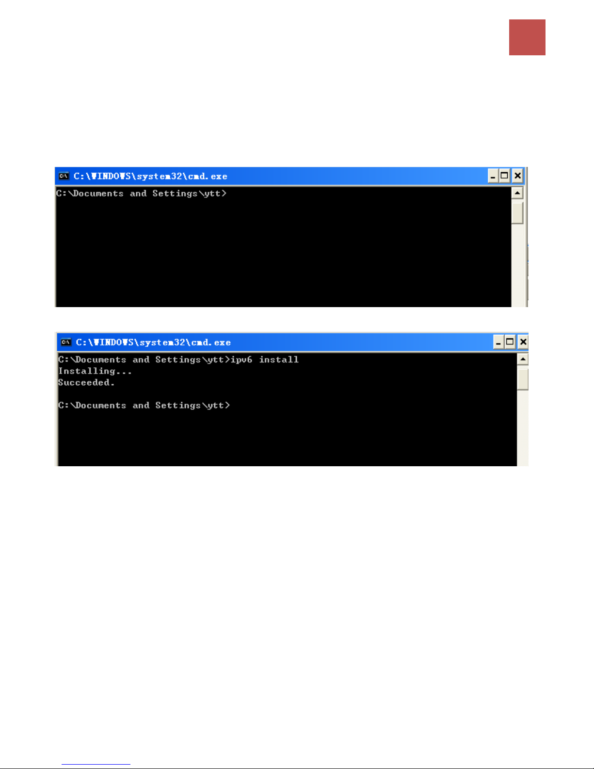
IPv6 is supported by Windows XP, but you need to install it first.
Please follow the steps to install IPv6:
1. On the Desktop, Click Start > Run, type cmd, then press Enter key in the keyboard, the following
screen appears.
2. Key in command ipv6 install
Installation of IPv6 is now completed. Please test it to see if it works or not. .
Page 30
Basic Installation
26
BEC 9800VN User Manual
Default Settings
Before configuring the router, you need to know the following default settings.
Web Interface: (Username and Password)
Username: admin
Password: admin
The default username and password are “admin” and “admin” respectively.
Device LAN IP Settings
IP Address: 192.168.1.254
Subnet Mask: 255.255.255.0
DHCP Server:
DHCP server is enabled.
Start IP Address: 192.168.1.100
IP pool counts: 100
Attention
If you ever forget the username/password to login to the router, you may
press the RESET button up to 6 seconds then release it to restore the factory
default settings.
Caution: After pressing the RESET button for more than 6 seconds then
release it, to be sure you power cycle the device again.
Page 31

Basic Installation
27
BEC 9800VN User Manual
Information from Your ISP
Before configuring this device, you have to check with your ISP (Internet Service Provider) what kind
of service is provided such as EWAN ((Dynamic IP address, Static IP address, PPPoE, Bridge Mode).
Gather the information as illustrated in the following table and keep it for reference.
PPPoE
Username, Password, Service Name, and Domain Name
System (DNS) IP address (it can be automatically assigned by
your ISP when you connect or be set manually).
Dynamic IP Address
DHCP Client (it can be automatically assigned by your ISP when
you connect or be set manually).
Static IP Address
IP address, Subnet mask, Gateway address, and Domain Name
System (DNS) IP address (it is fixed IP address).
Bridge Mode
Pure Bridge
Page 32
Device Configuration /
Status
28
BEC 9800VN User Manual
CHAPTER 4: DEVICE CONFIGURATION
Login to your Device
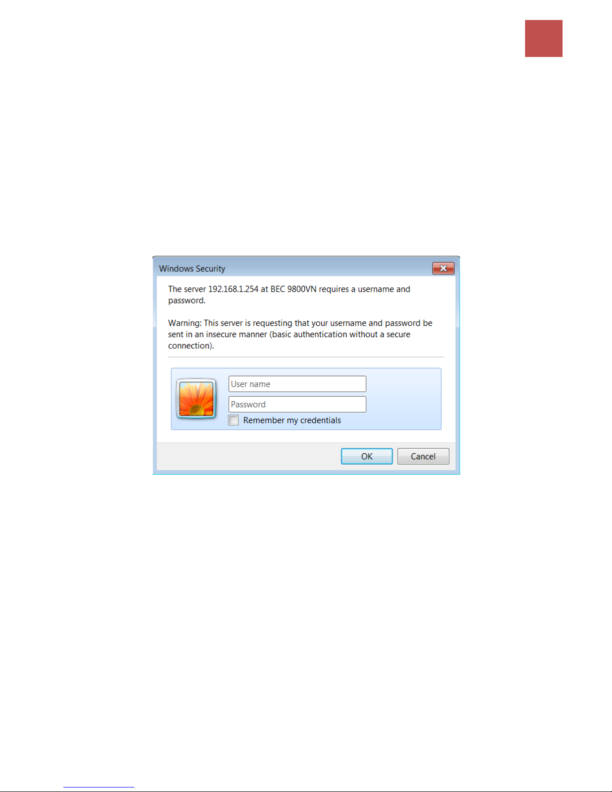
Open your web browser, enter the IP address of your router, which by default is 192.168.1.254, and
click “Go”, a user name and password window prompt appears.
The default username and password is “admin” and “admin” respectively for the Administrator.
NOTE: This username / password may vary by different Internet Service Providers.
Congratulations! You have successfully logged on to your BEC 9800VN.
Page 33

Device Configuration /
Status
29
BEC 9800VN User Manual
Once you have logged on to your 9800VN via your web browser, you can begin to set it up according
to your requirements. On the configuration homepage, the left navigation pane links you directly to the
setup pages, which includes:
Section
Status
Quick Start
(Wizard Setup)
Configuration
Language
Sub-Items
Device Info
Interface Setup
- Internet
- LAN
- Wireless
- Wireless MAC Filter
System Log
Dual WAN
- General Setting
Statistics
Advanced Setup
- Firewall
- Routing
- NAT
- Static DNS
- QoS
- Interface Grouping
- Port Isolation
- Time Schedule
DHCP Table
VoIP
- Basic
- Media
- Advanced
- Speed Dial
- Call Features
ARP Table
Access Management
- Device Management
- SNMP
- Universal Plug & Play (UPnP)
- Dynamic DNS
- Access Control
- Packet Filter
- CWMP (TR-069)
- Parental Control
- SAMBA & FTP Server
Wireless
ARP Table
Maintenance
- User Management
- Time Zone
- License
- Firmware & Configuration
- System Restart
- Diagnostic Tool
Disk Status
VoIP Status
Please see the relevant sections of this manual for detailed instructions on how to configure your BEC
9800VN gateway.
Page 34
Device Configuration /
Status
30
BEC 9800VN User Manual
Status
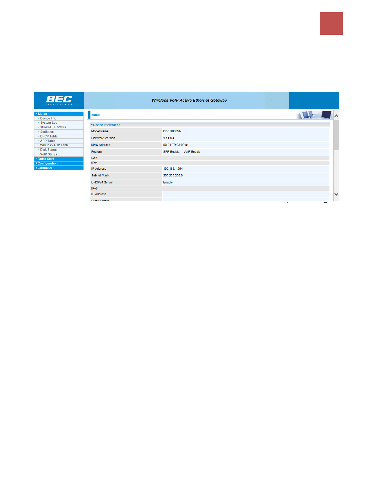
In this section, you can check the router working status, including Device Info, System Log,
Statistics, DHCP Table, ARP Table, Wireless ARP Table, Disk Status, and VoIP Status.
Page 35
Device Configuration /
Status
31
BEC 9800VN User Manual
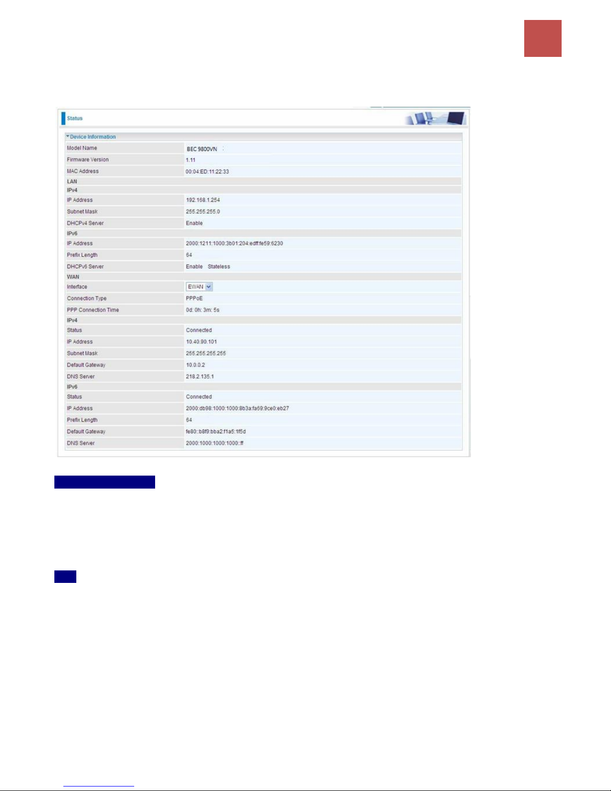
Device Info
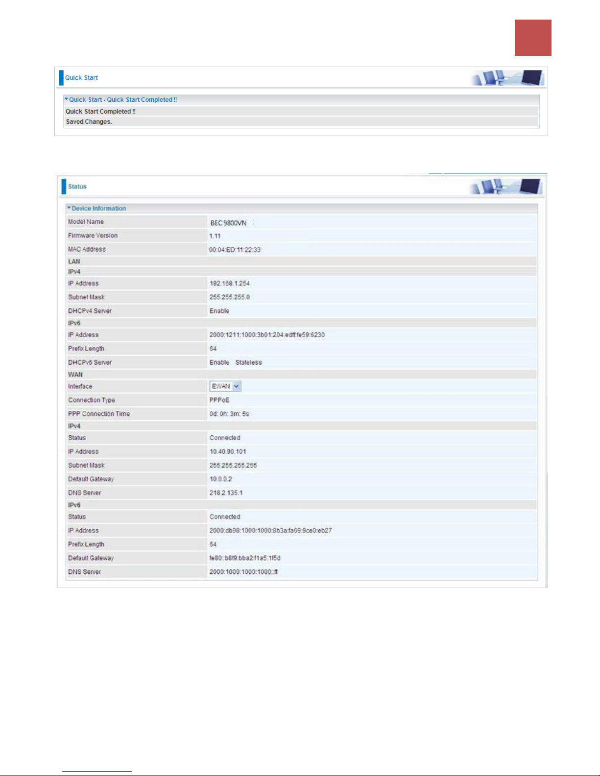
It contains basic information of the device.
Device Information
Model Name: Name of the router for identification purpose.
Firmware Version: Software version currently loaded in the router
MAC Address: A unique number that identifies the router
LAN
IPv4:
IP Address: LAN port IPv4 address.
Subnet Mask: LAN port IP subnet mask.
DHCPv4 Server: LAN port DHCP role - Enabled, Relay or Disabled.
IPv6:
IP Address: LAN port IPv6 address.
Prefix Length: The prefix length
DHCPv6 Server: The DHCP status.
Page 36

Device Configuration /
Status
32
BEC 9800VN User Manual
WAN
Interface: WAN connection options.
Service: The WAN interface service index.
PPP Connection Time: the uptime of the PPP connection.
IPv4:
Status: The connection status, either being connected or not in connected.
IP Address: WAN port IP address.
Subnet Mask: WAN port IP subnet mask.
Default Gateway: The IP address of the default gateway.
DNS Server: DNS information.
IPv6:
Status: The IPv6 connection status.
IP Address: WAN port IPv6 address.
Prefix Length: The prefix length of IPv6 address.
Default Gateway: The IP address of the default gateway.
DNS Server: DNS information.
Page 37
Device Configuration /
Status
33
BEC 9800VN User Manual
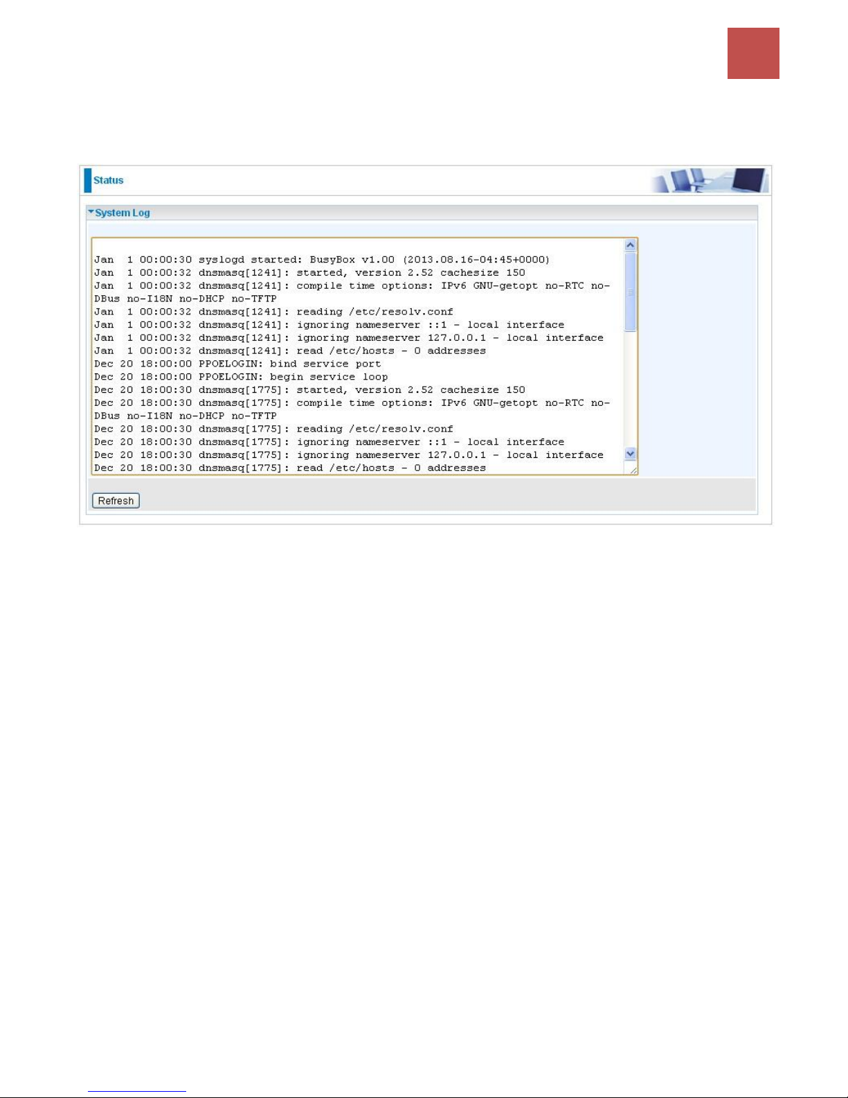
System Log
In system log, you can check the operations status and any glitches to the router.
Refresh: Press this button to refresh the statistics.
Page 38
Device Configuration /
Status
34
BEC 9800VN User Manual
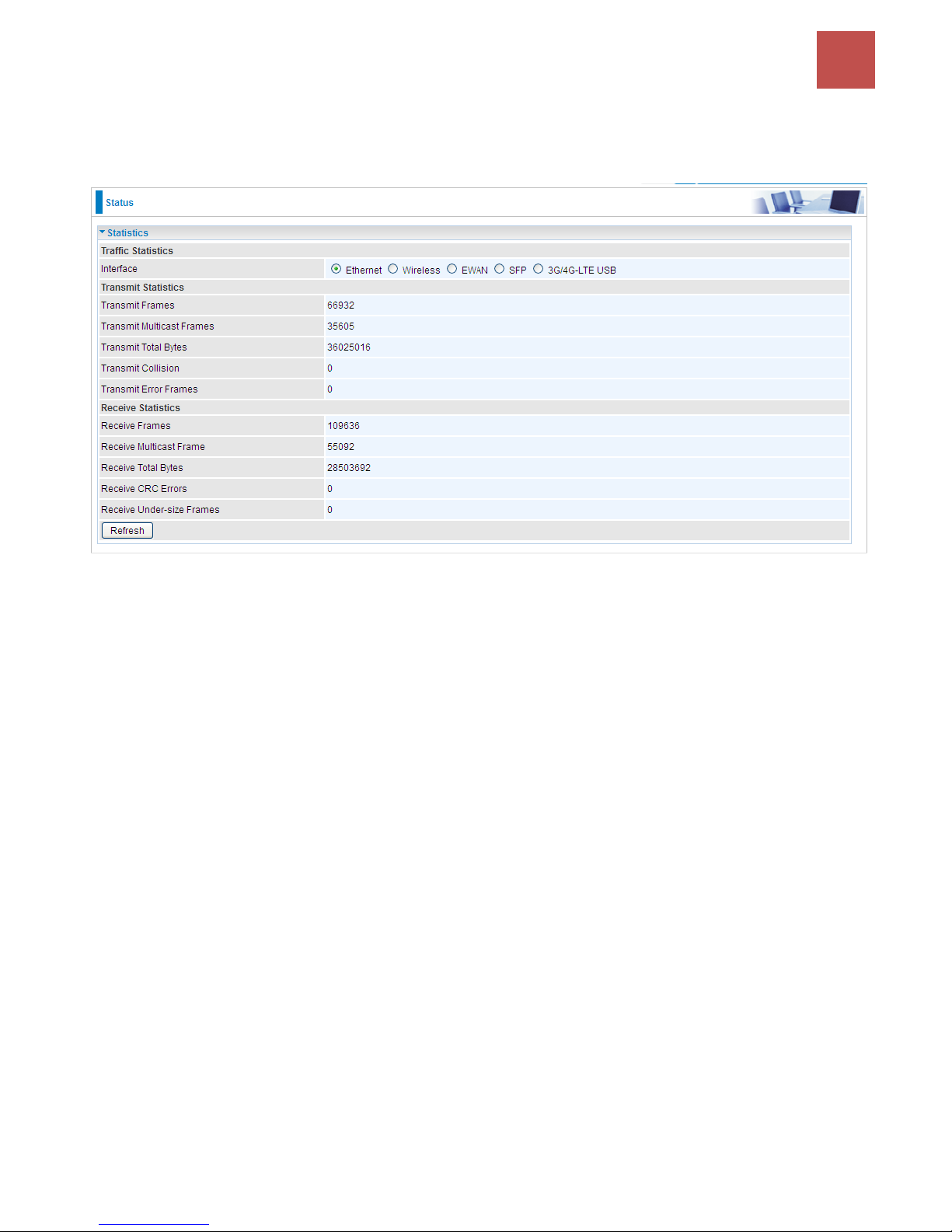
Statistics
Ethernet
Interface: List all available network interfaces in the router. You are currently checking on the physical
status of the Ethernet port.
Transmit Frames: This field displays the number of frames transmitted until the latest second.
Transmit Multicast Frames: This field displays the number of multicast frames transmitted until the
latest second.
Transmit Total Bytes: This field displays the number of bytes transmitted until the latest second.
Transmit Collision: This is the number of collisions on this port.
Transmit Error Frames: This field displays the number of error packets on this port.
Receive Frames: This field displays the number of frames received until the latest second.
Receive Multicast Frames: This field displays the number of multicast frames received until the latest
second.
Receive Total Bytes: This field displays the number of bytes received until the latest second.
Receive CRC Errors: This field displays the number of error packets on this port.
Receive Under-size Frames: This field displays the number of under-size frames received until the
latest second.
Refresh: Press this button to refresh the statistics.
Page 39
Device Configuration /
Status
35
BEC 9800VN User Manual
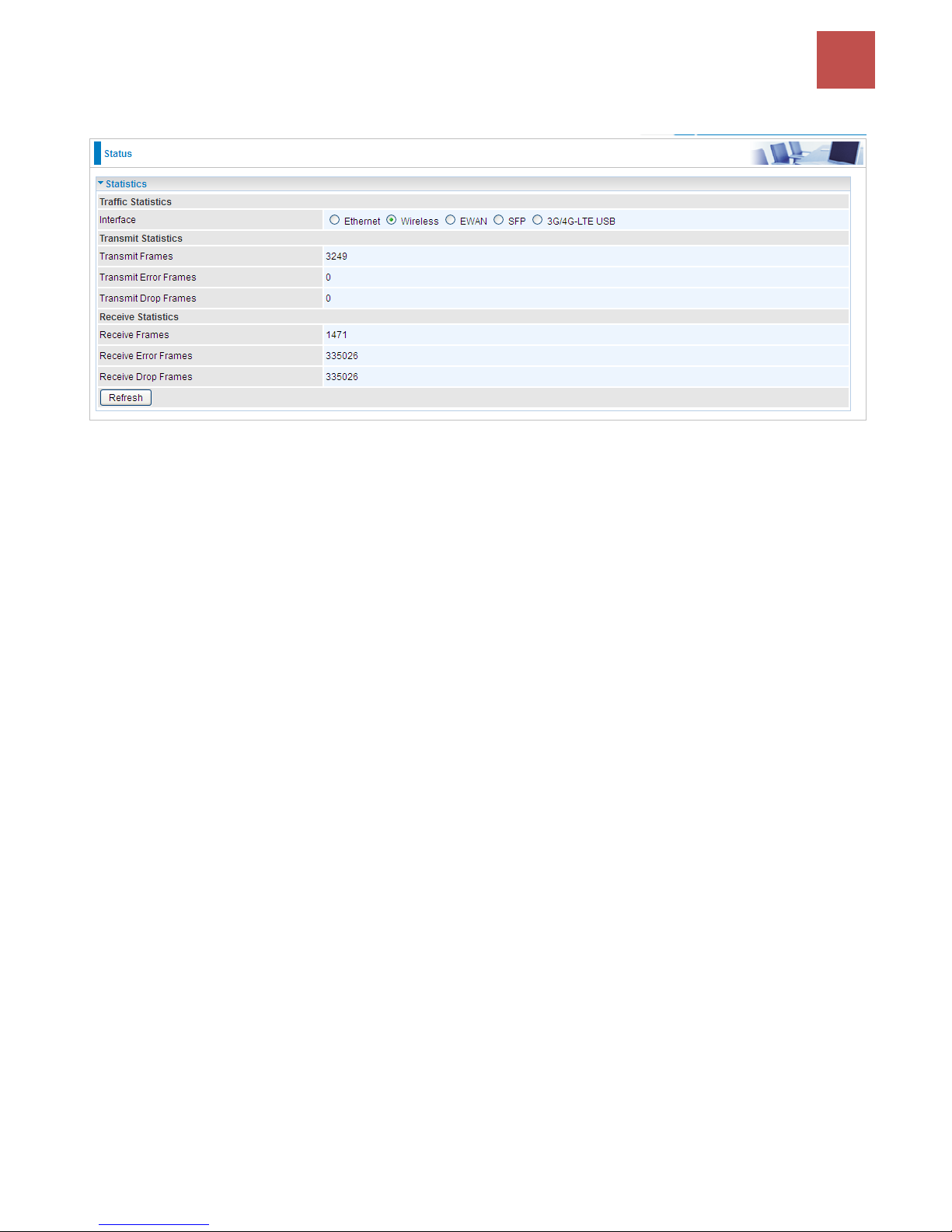
Wireless
Interface: List all available network interfaces in the router. You are currently checking on the physical
status of the Wireless.
Transmit Frames: This field displays the number of frames transmitted until the latest second.
Transmit Error Frames: This field displays the number of error frames transmitted until the latest
second.
Transmit Drop Frames: This field displays the number of drop frames transmitted until the latest
second.
Receive Frames: This field displays the number of frames received until the latest second.
Receive Error Frames: This field displays the number of error frames received until the latest second.
Receive Drop Frames: This field displays the number of drop frames received until the latest second.
Refresh: Press this button to refresh the statistics.
Page 40
Device Configuration /
Status
36
BEC 9800VN User Manual
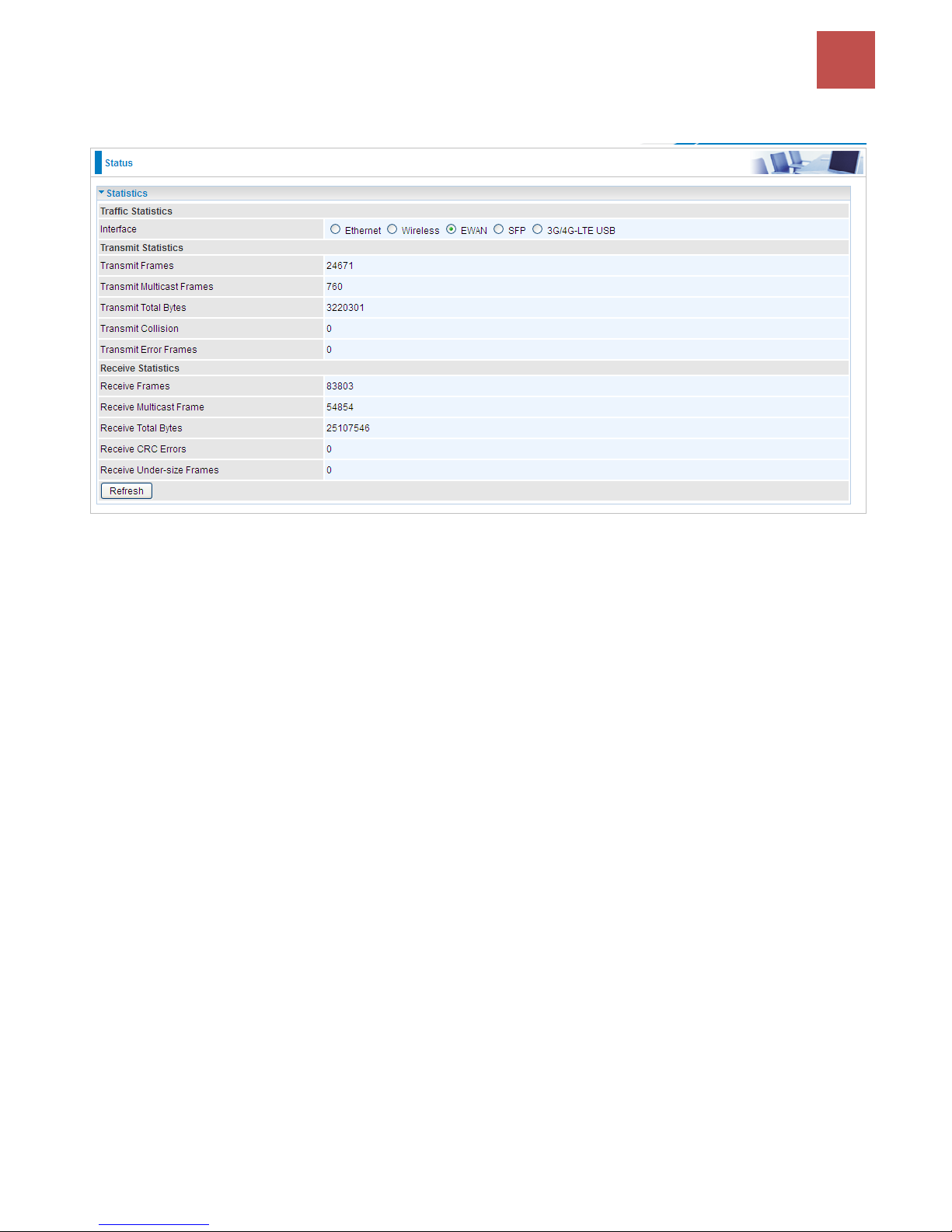
EWAN
Interface: List all available network interfaces in the router. You are currently checking on the physical
status of the EWAN port.
Transmit Frames: This field displays the total number of frames transmitted until the latest second.
Transmit Multicast Frames: This field displays the total number of multicast frames transmitted till
the latest second.
Transmit Total Bytes: This field displays the total number of bytes transmitted until the latest second.
Transmit Collision: This is the number of collisions on this port.
Transmit Error Frames: This field displays the number of error packets on this port.
Receive Frames: This field displays the number of frames received until the latest second.
Receive Multicast Frames: This field displays the number of multicast frames received until the latest
second.
Receive Total Bytes: This field displays the number of bytes received until the latest second.
Receive CRC Errors: This field displays the number of error packets on this port.
Receive Under-size Frames: This field displays the number of under-size frames received until the
latest second.
Refresh: Press this button to refresh the statistics.
Page 41
Device Configuration /
Status
37
BEC 9800VN User Manual
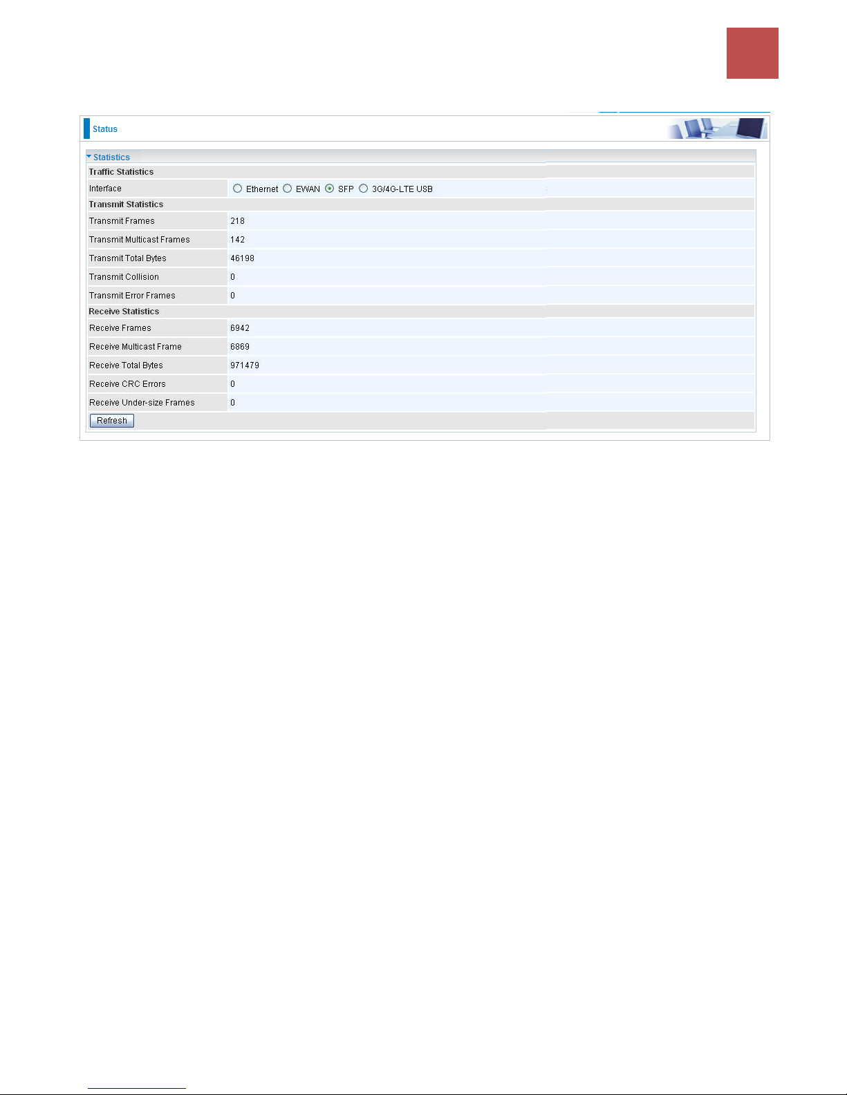
SFP
Transmit Frames: This field displays the total number of frames transmitted until the latest second.
Transmit Multicast Frames: This field displays the total number of multicast frames transmitted till
the latest second.
Transmit Total Bytes: This field displays the total number of bytes transmitted until the latest second.
Transmit Collision: This is the number of collisions on this port.
Transmit Error Frames: This field displays the number of error packets on this port.
Receive Frames: This field displays the number of frames received until the latest second.
Receive Multicast Frames: This field displays the number of multicast frames received until the latest
second.
Receive Total Bytes: This field displays the number of bytes received until the latest second.
Receive CRC Errors: This field displays the number of error packets on this port.
Receive Under-size Frames: This field displays the number of under-size frames received until the
latest second.
Refresh: Press this button to refresh the statistics.
Page 42
Device Configuration /
Status
38
BEC 9800VN User Manual
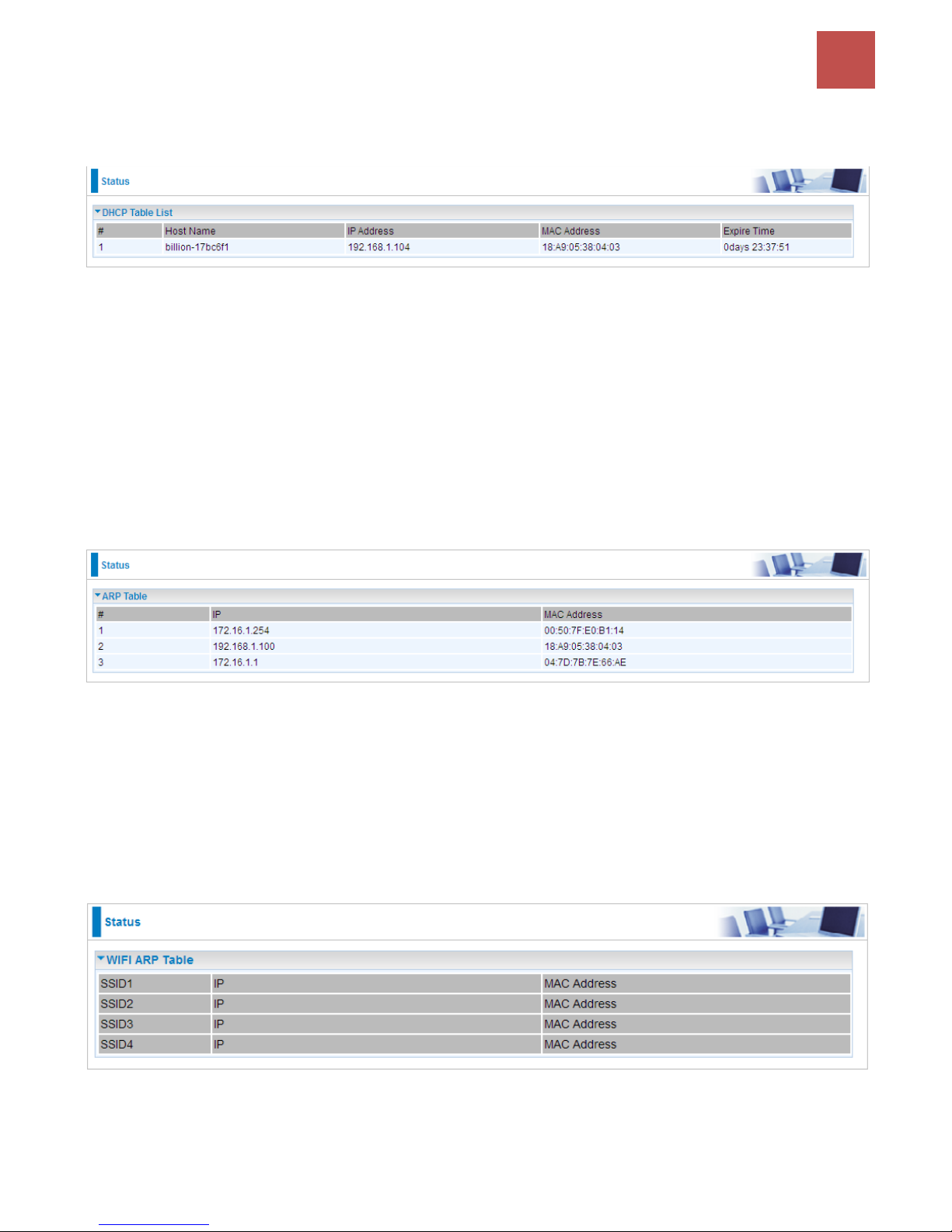
DHCP Table
DHCP table displays the devices connected to the router with clear information.
#: The index identifying the connected devices.
Host Name: Show the hostname of the PC.
IP Address: The IP allocated to the device.
MAC Address: The MAC of the connected device.
Expire Time: The total remaining interval since the IP assignment to the PC.
ARP Table
This section displays the router’s ARP (Address Resolution Protocol) results, which shows the
mapping of Internet (IP) addresses to Ethernet (MAC) addresses.
#: The index marking ARP resolution results.
IP Address: Show the IP Address that the MAC address maps to.
MAC Address: Show the MAC address that is corresponded to the IP address it is mapped to.
Wireless ARP Table
This section displays the router’s ARP (Address Resolution Protocol) results, which shows the
mapping of Internet (IP) addresses to the Wireless (MAC) addresses.
SSID#: List of Wireless Access Point (AP) index.
IP Address: Display current connected / associated IP Address of Wireless client(s).
MAC Address: Display current connected / associated Wireless client’s MAC address that is
Page 43
Device Configuration /
Status
39
BEC 9800VN User Manual
corresponded to the IP address.
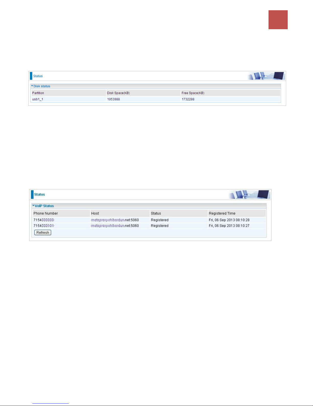
Disk Status
Partition: Display the USB storage partition.
Disk Space (KB): Display the total storage space of the NAS in Kbytes unit.
Free Space (KB): Display the available space in Kbytes unit.
VoIP Status
VoIP status gives you a directive picture on the registered VoIP accounts.
Phone Number: The number you use to register in the Basic page of VoIP.
Host: Show the IP address and port number of SIP Registrar.
Status: The status of the registered SIP account.
Registered Time: The duration the account has been successfully registered to the SIP registrar.
Page 44
Device Configuration /
Quick Start
40
BEC 9800VN User Manual
Quick Start
This is a useful and easy utility to help you to setup the router quickly and to connect to your ISP
(Internet Service Provider) with only a few steps. It will guide you step by step to setup time zone and
WAN settings of your device. The Quick Start Wizard is a helpful guide for the first-time users to the
device.
For detailed instructions on configuring WAN settings, see refer to the Interface Setup section.
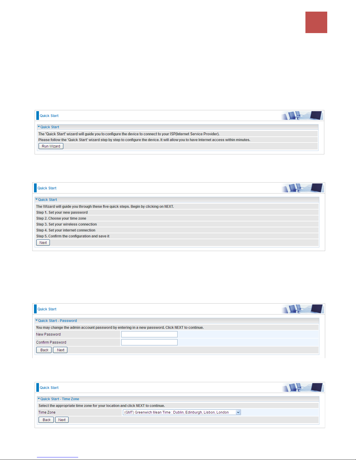
Click NEXT to move on to Step 1.
Step1. Set new password of the “admin” account to access for router management. The default is
“admin”. Once changed, please use this new password next time when accessing to the router. Click
NEXT to continue.
Step2: Choose your time zone. Click NEXT to continue.
Page 45
Device Configuration /
Quick Start
41
BEC 9800VN User Manual
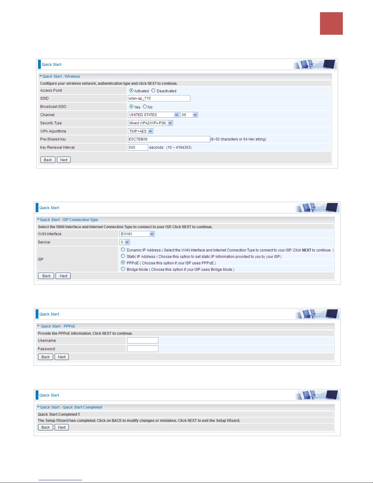
Step3: Set up your wireless connection if you want to connect to the Internet wirelessly on your PCs.
Click NEXT to continue.
Step4: Set up your Internet connection.
1). Select an appropriate WAN connection protocol then click NEXT to continue.
2). If selected PPPoE, please enter PPPoE account information provided by your ISP. Click NEXT to
continue.
3).The Setup Wizard has completed. Click on BACK to modify changes or mistakes. Click NEXT to
save the current settings.
4). Quick Start Completed!
Page 46
Device Configuration /
Quick Start
42
BEC 9800VN User Manual
Switch to Status > Device Info to view the status.
Page 47

Device Configuration /
Interface Setup
43
BEC 9800VN User Manual
Configuration
Click to access and configure the available features in the following: Interface Setup, Dual WAN,
Advanced Setup, VoIP, Access Management, and Maintenance.
These functions are described in the following sections.
Interface Setup
Here are the features under Interface Setup: Internet, LAN, Wireless and Wireless MAC Filter.
Page 48
Device Configuration /
Interface Setup
44
BEC 9800VN User Manual
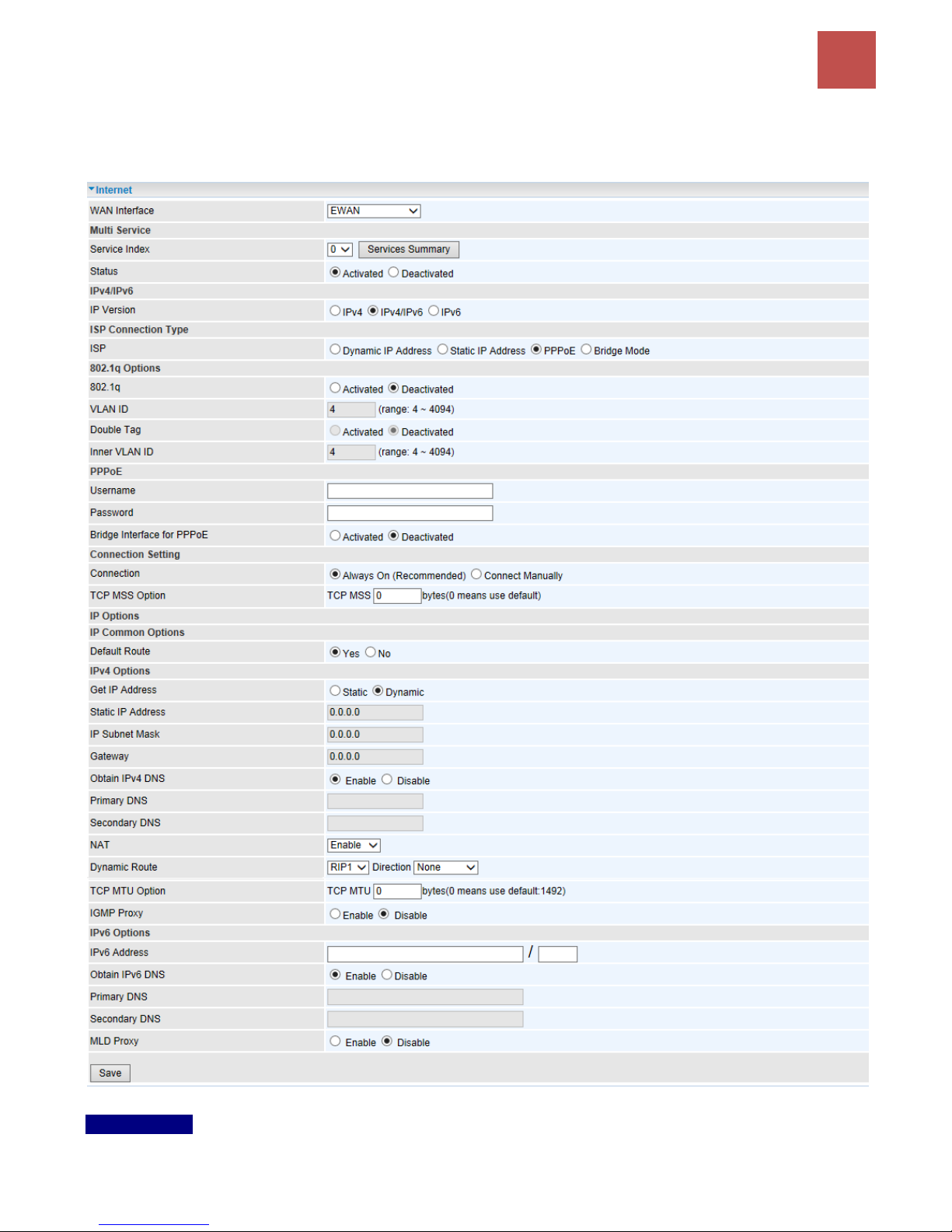
Internet
EWAN
Multi Service
Service Index: The index marks the EWAN interface of different ISP type, ranging from 0-7.
Page 49
Device Configuration /
Interface Setup
45
BEC 9800VN User Manual
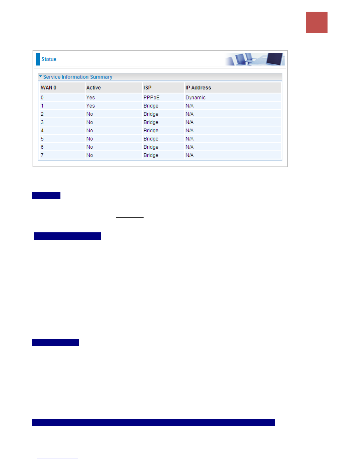
Service Summary: The overall service information.
Status: Select to enable or disable the service.
IPv4/IPv6
IP Version: Choose IPv4, IPv4/IPv6, IPv6 based on your environment. If you don’t know which one to
choose from, please choose IPv4/IPv6 instead.
ISP Connection Type:
ISP: Select the encapsulation type your ISP uses.
Dynamic IP: Select this option if your ISP provides you an IP address automatically.
Static IP: Select this option to set static IP information. You will need to enter in the Connection
type, IP address, subnet mask, and gateway address, provided to you by your ISP. Each IP
address entered in the fields must be in the appropriate IP form. IP address from by four IP
octets separated by a dot (xx.xx.xx.xx). The Router will not accept the IP address if it is not in
this format.
PPPoE: Select this option if your ISP requires you to use a PPPoE connection.
Bridge: Select this mode if you want to use this device as an OSI Layer 2 device like a switch.
802.1q Options
802.1q: When activated, please enter a VLAN ID.
VLAN ID: It is a parameter to specify the VLAN which the frame belongs. Enter the VLAN ID
identification, tagged: 4-4095.
Double Tag (Q-in-Q): Enable to activate the Q-in-Q feature.
Inner VLAN ID: Specify the inner/ending VLAN ID of the final packet. Enter the VLAN ID identification,
tagged: 4-4095
PPPoE (If selected PPPoE as WAN Connection Type; otherwise, skip this part)
Username: Enter the user name provided by your ISP.
Page 50

Device Configuration /
Interface Setup
46
BEC 9800VN User Manual
Password: Enter the password provided by your ISP.
Bridge Interface for PPPoE: When “Activated”, the device will gain WAN IP from your ISP with the
PPPoE account. But if your PC is connected to the router working as a DHCP client, in this mode, the
device acts as a NAT router; while if you dial up with the account within your PC, the device will then
work as a bridge forwarding the PPPoE information to the PPPoE server and send the response to
your PC, thus your PC gets a WAN IP working in the internet.
Connection Setting
Connection:
Always On: Click on Always On to establish a PPPoE session during start up and to
automatically re-establish the PPPoE session when disconnected by the ISP.
Connect Manually: Select Connect Manually when you don't want the connection up all the
time.
TCP MSS Option: Enter the TCP Maximum Segment Size (MSS).
IP Options
Default Route: Select Yes to use this interface as default route interface.
IPv4 Options
Get IP Address: Choose Static or Dynamic
Static IP Address: If Static is selected in the above field, please enter the specific IP address you get
from ISP and the following IP subnet mask and gateway address.
IP Subnet Mask: The default is 0.0.0.0. User can change it to other such as 255.255.255.0.Type the
subnet mask assigned to you by your ISP (if given).
Gateway: Enter the specific gateway IP address you get from ISP.
NAT: Select Enable if you use this router to hold a group of PCs to get access to the internet.
Dynamic Route:
RIP Version: (Routing Information protocol) Select this option to specify the RIP version,
including RIP-1, RIP-2.
RIP Direction: Select this option to specify the RIP direction.
- None is for disabling the RIP function.
- Both means the router will periodically send routing information and accept routing
information then incorporate into routing table.
- IN only means the router will only accept but will not send RIP packet.
- OUT only means the router will only send but will not accept RIP packet.
TCP MTU Option: Maximum Transmission Unit, the maximum is 1500.
IGMP Proxy: IGMP (Internet Group Multicast Protocol) is a network-layer protocol used to establish
membership in a Multicast group. Choose whether enable IGMP proxy.
Page 51

Device Configuration /
Interface Setup
47
BEC 9800VN User Manual
IPv6 options (only when choose IPv4/IPv6 or just IPv6 in IP version field above):
IPv6 Address: Type the WAN IPv6 address from your ISP.
Obtain IPv6 DNS: Choose if you want to obtain DNS automatically.
Primary/Secondary: if you choose Disable in the Obtain IPv6 DNS field, please type the exactly
primary and secondary DNS.
MLD Proxy: MLD (Multicast Listener Discovery Protocol) is to IPv6 just as IGMP to IPv4. It is a
Multicast Management protocol for IPv6 multicast packets.
When router’s Internet configuration is finished successfully, you can go to status to get the connection
information.
Page 52
Device Configuration /
Interface Setup
48
BEC 9800VN User Manual
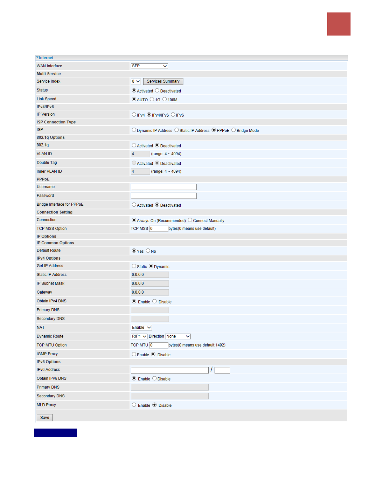
SFP
Multi Service
Service Index: The index marks the EWAN interface of different ISP type, ranging from 0-7.
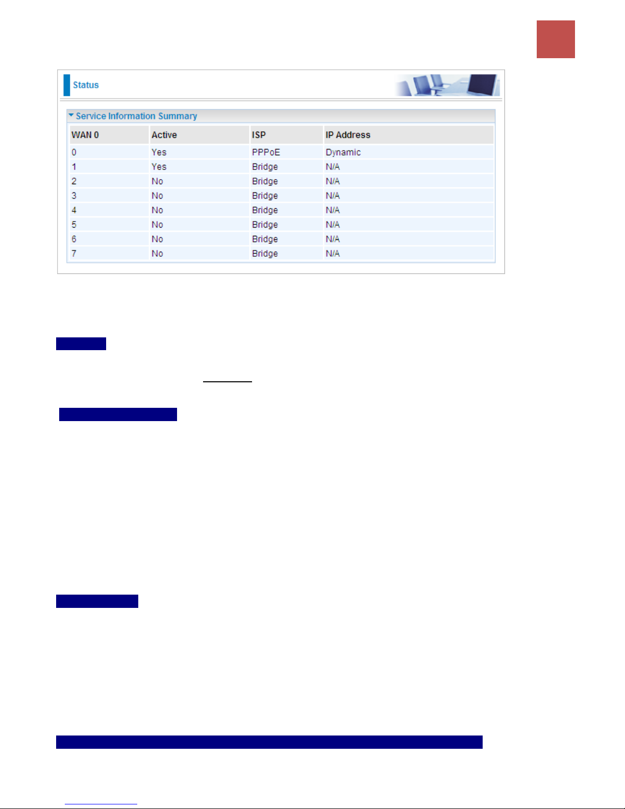
Service Summary: The overall service information.
Page 53
Device Configuration /
Interface Setup
49
BEC 9800VN User Manual
Status: Select to enable or disable the service.
Line Speed: Specify the desire speed (Automatic / 1Gbps /100M) for SFP connectivitive
IPv4/IPv6
IP Version: Choose IPv4, IPv4/IPv6, IPv6 based on your environment. If you don’t know which one to
choose from, please choose IPv4/IPv6 instead.
ISP Connection Type:
ISP: Select the encapsulation type your ISP uses.
Dynamic IP: Select this option if your ISP provides you an IP address automatically.
Static IP: Select this option to set static IP information. You will need to enter in the Connection
type, IP address, subnet mask, and gateway address, provided to you by your ISP. Each IP
address entered in the fields must be in the appropriate IP form. IP address from by four IP
octets separated by a dot (xx.xx.xx.xx). The Router will not accept the IP address if it is not in
this format.
PPPoE: Select this option if your ISP requires you to use a PPPoE connection.
Bridge: Select this mode if you want to use this device as an OSI Layer 2 device like a switch.
802.1q Options
802.1q: When activated, please enter a VLAN ID.
VLAN ID: It is a parameter to specify the VLAN which the frame belongs. Enter the VLAN ID
identification, tagged: 4-4095.
Double Tag (Q-in-Q): Enable to activate the Q-in-Q feature.
Inner VLAN ID: Specify the inner/ending VLAN ID of the final packet. Enter the VLAN ID identification,
tagged: 4-4095
PPPoE (If selected PPPoE as WAN Connection Type; otherwise, skip this part)
Username: Enter the user name provided by your ISP.
Page 54

Device Configuration /
Interface Setup
50
BEC 9800VN User Manual
Password: Enter the password provided by your ISP.
Bridge Interface for PPPoE: When “Activated”, the device will gain WAN IP from your ISP with the
PPPoE account. But if your PC is connected to the router working as a DHCP client, in this mode, the
device acts as a NAT router; while if you dial up with the account within your PC, the device will then
work as a bridge forwarding the PPPoE information to the PPPoE server and send the response to
your PC, thus your PC gets a WAN IP working in the internet.
Connection Setting
Connection:
Always On: Click on Always On to establish a PPPoE session during start up and to
automatically re-establish the PPPoE session when disconnected by the ISP.
Connect Manually: Select Connect Manually when you don't want the connection up all the
time.
TCP MSS Option: Enter the TCP Maximum Segment Size (MSS).
IP Options
Default Route: Select Yes to use this interface as default route interface.
IPv4 Options
Get IP Address: Choose Static or Dynamic
Static IP Address: If Static is selected in the above field, please enter the specific IP address you get
from ISP and the following IP subnet mask and gateway address.
IP Subnet Mask: The default is 0.0.0.0. User can change it to other such as 255.255.255.0.Type the
subnet mask assigned to you by your ISP (if given).
Gateway: Enter the specific gateway IP address you get from ISP.
NAT: Select Enable if you use this router to hold a group of PCs to get access to the internet.
Dynamic Route:
RIP Version: (Routing Information protocol) Select this option to specify the RIP version,
including RIP-1, RIP-2.
RIP Direction: Select this option to specify the RIP direction.
- None is for disabling the RIP function.
- Both means the router will periodically send routing information and accept routing
information then incorporate into routing table.
- IN only means the router will only accept but will not send RIP packet.
- OUT only means the router will only send but will not accept RIP packet.
TCP MTU Option: Maximum Transmission Unit, the maximum is 1500.
IGMP Proxy: IGMP (Internet Group Multicast Protocol) is a network-layer protocol used to establish
membership in a Multicast group. Choose whether enable IGMP proxy.
Page 55

Device Configuration /
Interface Setup
51
BEC 9800VN User Manual
IPv6 options (only when choose IPv4/IPv6 or just IPv6 in IP version field above):
IPv6 Address: Type the WAN IPv6 address from your ISP.
Obtain IPv6 DNS: Choose if you want to obtain DNS automatically.
Primary/Secondary: if you choose Disable in the Obtain IPv6 DNS field, please type the exactly
primary and secondary DNS.
MLD Proxy: MLD (Multicast Listener Discovery Protocol) is to IPv6 just as IGMP to IPv4. It is a
Multicast Management protocol for IPv6 multicast packets.
When router’s Internet configuration is finished successfully, you can go to status to get the connection
information.
Page 56
Device Configuration /
Interface Setup
52
BEC 9800VN User Manual
LAN
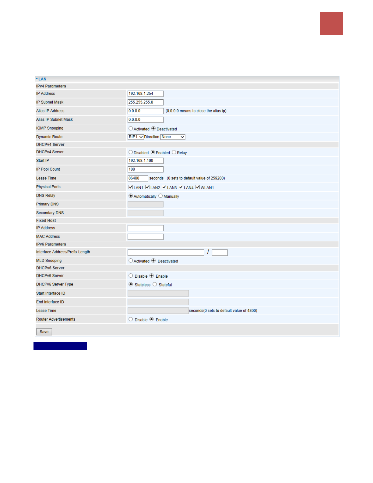
A Local Area Network (LAN) is a shared communication system to which many computers are
attached and is limited to the immediate area, usually the same building or floor of a building.
IPv4 Parameters
IP Address: Enter the IP address of Router in dotted decimal notation, for example, 192.168.1.254
(factory default).
IP Subnet Mask: The default is 255.255.255.0. User can change it to other such as 255.255.255.128.
Alias IP Address: This is for local networks virtual IP interface. Specify an IP address on this virtual
interface.
Alias IP Subnet Mask: Specify a subnet mask on this virtual interface.
IGMP Snooping: Select Activated to enable IGMP Snooping function, Without IGMP snooping,
multicast traffic is treated in the same manner as broadcast traffic - that is, it is forwarded to all ports.
With IGMP snooping, multicast traffic of a group is only forwarded to ports that have members of that
group.
Dynamic Route: Select the RIP version from RIP1 or RIP2.
Page 57
Device Configuration /
Interface Setup
53
BEC 9800VN User Manual
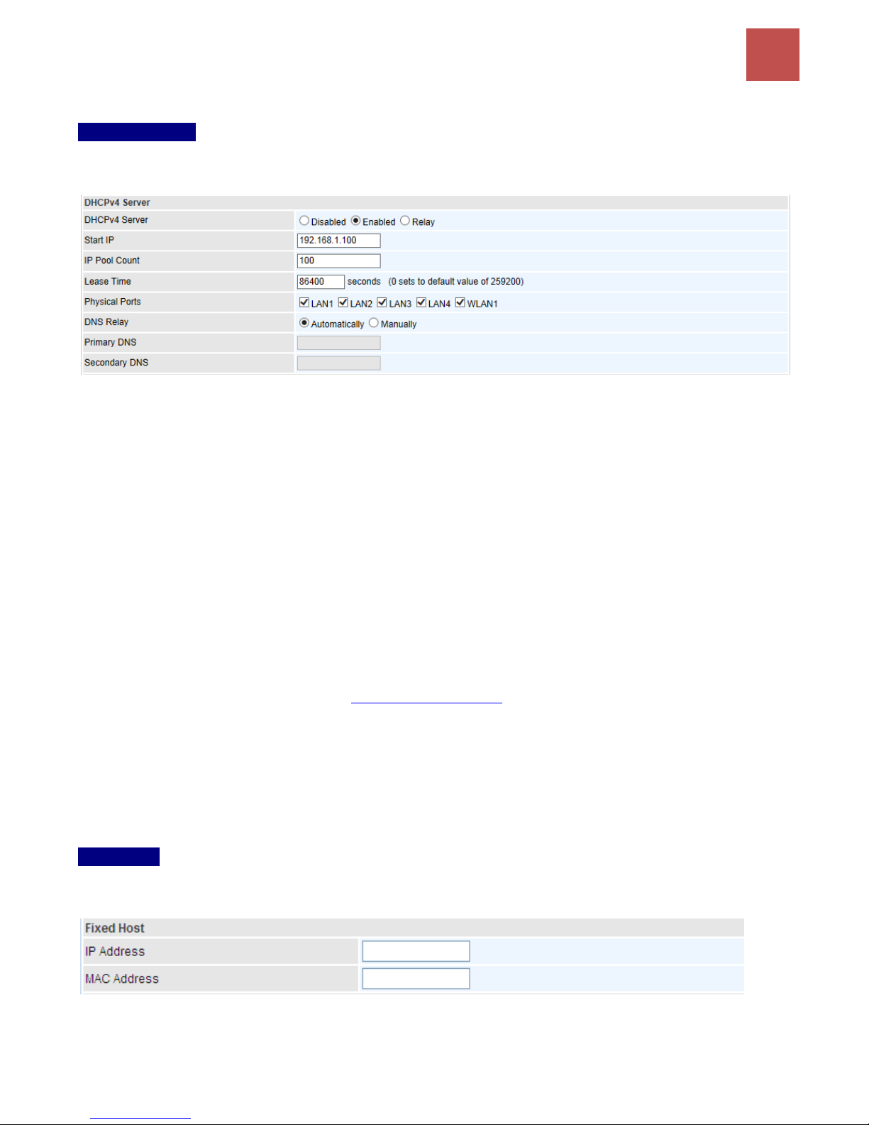
DHCPv4 Server
DHCP (Dynamic Host Configuration Protocol) allows individual clients to obtain TCP/IP configuration
at start-up from a server.
DHCPv4 Server: If set to Enabled, your BEC 9800VN can assign IP addresses, default gateway and
DNS servers to the DHCP client.
If set to Disabled, the DHCP server will be disabled.
If set to Relay, the BEC 9800VN acts as a surrogate DHCP server and relays DHCP requests
and responses between the remote server and the clients. Enter the IP address of the actual,
remote DHCP server in the Remote DHCP Server field in this case.
When DHCP is used, the following items need to be set.
Start IP: This field specifies the first of the contiguous addresses in the IP address pool.
IP Pool Count: This field specifies the count of the IP address pool.
Lease Time: The current lease time of client.
Physical Ports: Select to determine if the DHCPv4 server is applicable to the specific port or ports. By
default, all ports can obtain local IP from DHCPv4 server.
DNS Relay Select Automatically obtained or Manually set (if selected. Please set the exactly
information). If you set Static IP in the ISP Connection Type field, then select Manually here and set
the specific DNS information.
Primary DNS Server: Enter the IP addresses of the DNS servers. The DNS servers are passed to the
DHCP clients along with the IP address and the subnet mask.
Secondary DNS Server: Enter the IP addresses of the DNS servers. The DNS servers are passed to
the DHCP clients along with the IP address and the subnet mask.
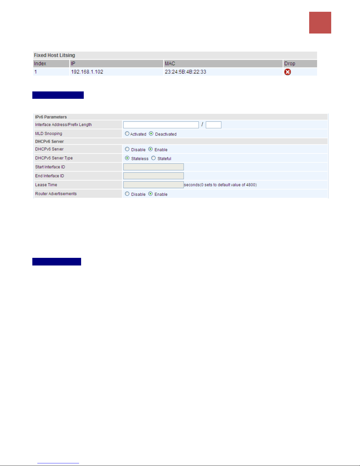
Fixed Host
In this field, users can map the specific IP (must in the DHCP IP pool) for some specific MAC, and this
information can be listed in the following table.
IP Address: Enter the specific IP. For example: 192.168.1.110.
MAC Address: Enter the responding MAC. For example: 00:0A:F7:45:6D:ED
Page 58
Device Configuration /
Interface Setup
54
BEC 9800VN User Manual
When added, you can see the ones listed as showed below:
IPv6 Parameters
The IPv6 address composes of two parts, thus, the prefix and the interface ID.
Interface Address / Prefix Length: Enter a static LAN IPv6 address. If you are not sure what to do
with this field, please leave it empty as if contains false information it could result in LAN devices not
being able to access other IPv6 device. Router will take the same WAN’s prefix to LAN side if the field
is empty.
MLD Snooping: Similar to IGMP Snooping, but applicable for IPv6.
DHCPv6 Server
There are two methods to dynamically configure IPv6 address on hosts, Stateless and Stateful.
Stateless auto-configuration requires no manual configuration of hosts, minimal (if any)
configuration of routers, and no additional servers. The stateless mechanism allows a host to generate
its own addresses using a combination of locally available information (MAC address) and information
(prefix) advertised by routers. Routers advertise prefixes that identify the subnet(s) associated with a
link, while hosts generate an "interface identifier" that uniquely identifies an interface on a subnet. An
address is formed by combining the two. When using stateless configuration, you needn’t configure
anything on the client.
Stateful configuration, for example using DHCPv6 (which resembles its counterpart DHCP in IPv4.)
In the stateful auto configuration model, hosts obtain interface addresses and/or configuration
information and parameters from a DHCPv6 server. The Server maintains a database that keeps track
of which addresses have been assigned to which hosts.
DHCPv6 Server: Check whether to enable DHCPv6 server.
DHCPv6 Server Type: Select Stateless or Stateful. When DHCPv6 is enabled, this parameter is
available.
Stateless: If selected, the PCs in LAN are configured through RA mode, thus, the PCs in LAN
are configured through RA mode, to obtain the prefix message and generate an address using a
combination of locally available information (MAC address) and information (prefix) advertised
by routers, but they can obtain such information like DNS from DHCPv6 Server.
Stateful: If selected, the PCs in LAN will be configured like in IPv4 mode, thus obtain addresses
Page 59

Device Configuration /
Interface Setup
55
BEC 9800VN User Manual
and DNS information from DHCPv6 server.
Start interface ID: enter the start interface ID. The IPv6 address composed of two parts, thus, the
prefix and the interface ID. Interface is like the Host ID compared to IPv4.
End interface ID: enter the end interface ID.
Leased Time (hour): the leased time, similar to leased time in DHCPv4, is a time limit assigned to
clients, when expires, the assigned ID will be recycled and reassigned.
Issue Router Advertisement: Check to Enable or Disable the Issue Router Advertisement feature.
This feature is to send Router Advertisement messages periodically which would multicast the IPv6
Prefix information (similar to v4 network number 192.168.1.0) to all LAN devices if the field is enabled.
We suggest enabling this field.
Page 60
Device Configuration /
Interface Setup
56
BEC 9800VN User Manual
Wireless
This section introduces the wireless LAN and some basic configurations. Wireless LANs can be as
complex as a number of computers with wireless LAN cards communicating through access points
which bridge network traffic to the wired LAN.
Page 61

Device Configuration /
Interface Setup
57
BEC 9800VN User Manual
Access Point Settings
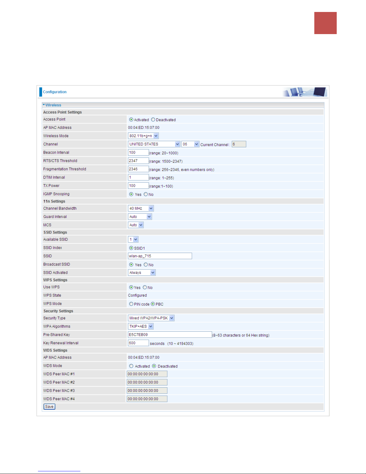
Access Point: Default setting is set to Activated. If you want to close the wireless interface, select
Deactivated.
AP MAC Address: The MAC address of wireless AP.
Wireless Mode: The default setting is 802.11b+g+n (Mixed mode). If you do not know or have both
11g and 11b devices in your network, then keep the default in mixed mode. From the drop-down
manual, you can select 802.11g if you have only 11g card. If you have only 11b card, then select
802.11b and if you only have 802.11n then select 802.11n.
Channel: The range of radio frequencies used by IEEE 802.11b/g/n wireless devices is called a
channel. There are Regulation Domains and Channel ID in this field. The Channel ID will be different
based on Regulation Domains. Select a channel from the drop-down list box.
Beacon interval: The Beacon Interval value indicates the frequency interval of the beacon. Enter a
value between 20 and 1000. A beacon is a packet broadcast by the Router to synchronize the wireless
network.
RTS/CTS Threshold: The RTS (Request To Send) threshold (number of bytes) for enabling RTS/CTS
handshake. Data with its frame size larger than this value will perform the RTS/CTS handshake. Enter
a value between 1500 and 2347.
Fragmentation Threshold: The threshold (number of bytes) for the fragmentation boundary for
directed messages. It is the maximum data fragment size that can be sent. Enter a value between 256
and 2346, even number only.
DTIM Interval: This value, between 1 and 255, indicates the interval of the Delivery Traffic Indication
Message (DTIM).
TX Power: The transmission power of the antennas, ranging from 1-100, the higher the more powerful
of the transmission performance.
IGMP Snooping: Enable or disable the IGMP Snooping function for wireless. Without IGMP snooping,
multicast traffic is treated in the same manner as broadcast traffic - that is, it is forwarded to all ports.
With IGMP snooping, multicast traffic of a group is only forwarded to ports that have members of that
group.”
11n Settings
Channel Bandwidth: Select either 20 MHz or 20/40 MHz for the channel bandwidth. The wider the
Channel bandwidth the better the performance will be.
Guard Interval: Select either 400nsec or 800nsec for the guard interval. The guard interval is here to
ensure that data transmission do not interfere with each other. It also prevents propagation delays,
echoing and reflections. The shorter the Guard Interval, the better the performance will be. We
recommend users to select Auto.
MCS: There are options 0~15 and AUTO to select for the Modulation and Coding Scheme. We
recommend users selecting AUTO.
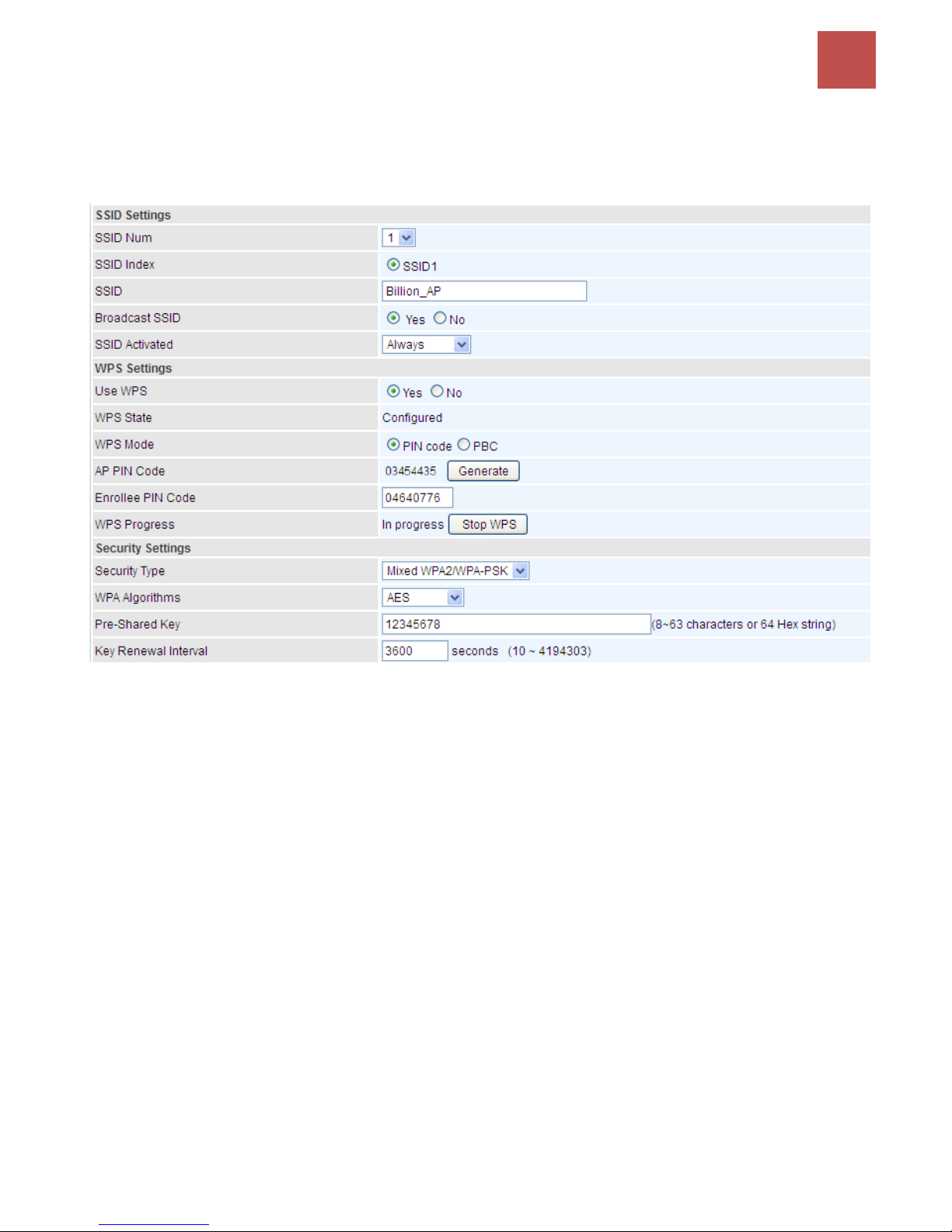
SSID Settings
Available SSID: User can determine how many virtual SSIDs to be used. Default is 1, maximum is 4.
SSID Index: Select the number of SSIDs you want to use; up to 4 SSIDs are available in the list.
SSID: The SSID is the unique name of a wireless access point (AP) to be distinguished from another.
Page 62
Device Configuration /
Interface Setup
58
BEC 9800VN User Manual
For security propose, change the default wlan-ap to a unique ID name to the AP which is already
built-in to the router’s wireless interface. Make sure your wireless clients have exactly the SSID as the
device, in order to get connected to your network.
Broadcast SSID: Select Yes to make the SSID visible so a station can obtain the SSID through
passive scanning. Select No to hide the SSID in so a station cannot obtain the SSID through passive
scanning.
SSID Activated: Select the time period during which the SSID is active. Default is always which
means the SSID will be active all the time without time control. See Time Schedule to set the timeslot
to flexibly control when the SSID functions.
WPS Settings
WPS (Wi-Fi Protected Setup) feature is a standard protocol created by Wi-Fi Alliance. This feature
greatly simplifies the steps needed to create a Wi-Fi network for a residential or an office setting. WPS
supports 2 types of configuration methods which are commonly known among consumers: PIN
Method & PBC Method.
WPS State: Display whether the WPS is configured or unconfigured.
WPS Mode: Select the mode which to start WPS, choose between PIN Code and PBC (Push Button).
Selecting Pin Code mode will require you to know the enrollee PIN code.
To future understand the two modes of configuration; please refer to the example of the Wi-Fi
Protected Setup.
Security Settings
Security Type: You can disable or enable wireless security for protecting wireless network. The
default type of wireless security is OPEN and to allow all wireless stations to communicate with the
access points without any data encryption.
To prevent unauthorized wireless stations from accessing data transmitted over the network, the router
offers secure data encryption, known as WEP and WPA.
There are five alternatives to select from: WEP 64-bit, WEP 128-bit, WPA-PSK, WPA2-PSK, and
Mixed WPA/WPA2-PSK. If you require high security for transmissions, please select WPA-PSK,
WPA2-PSK or WPA/WPA2-PSK.
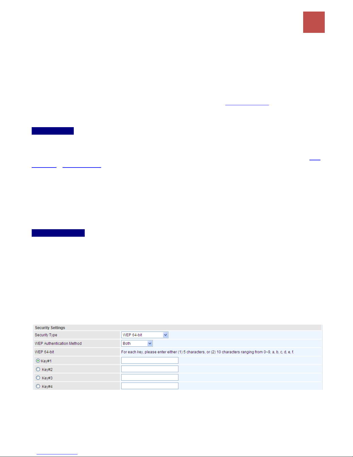
WEP
WEP Authentication Method: WEP authentication method, there are two methods of authentication
used, Open System authentication (OPENWEB) and Share Key authentication (SHAREDWEB). We
suggest you select OPENWEB.
Key 1 to Key 4: Enter the key to encrypt wireless data. To allow encrypted data transmission, the
WEP Encryption Key values on all wireless stations must be the same as the router. There are four
Page 63
Device Configuration /
Interface Setup
59
BEC 9800VN User Manual
keys for your selection. The input format is in HEX style, 5 and 13 HEX codes are required for
64-bitWEP and 128-bitWEP respectively.
If you chose WEP 64-bit, then enter any 5 ASCII characters or 10 hexadecimal characters ("0-9",
"A-F").
If you chose WEP 128-bit, then enter 13 ASCII characters or 26 hexadecimal characters ("0-9", "A-F").
You must configure all four keys, but only one key can be activated at any one time. The default key is
key 1.
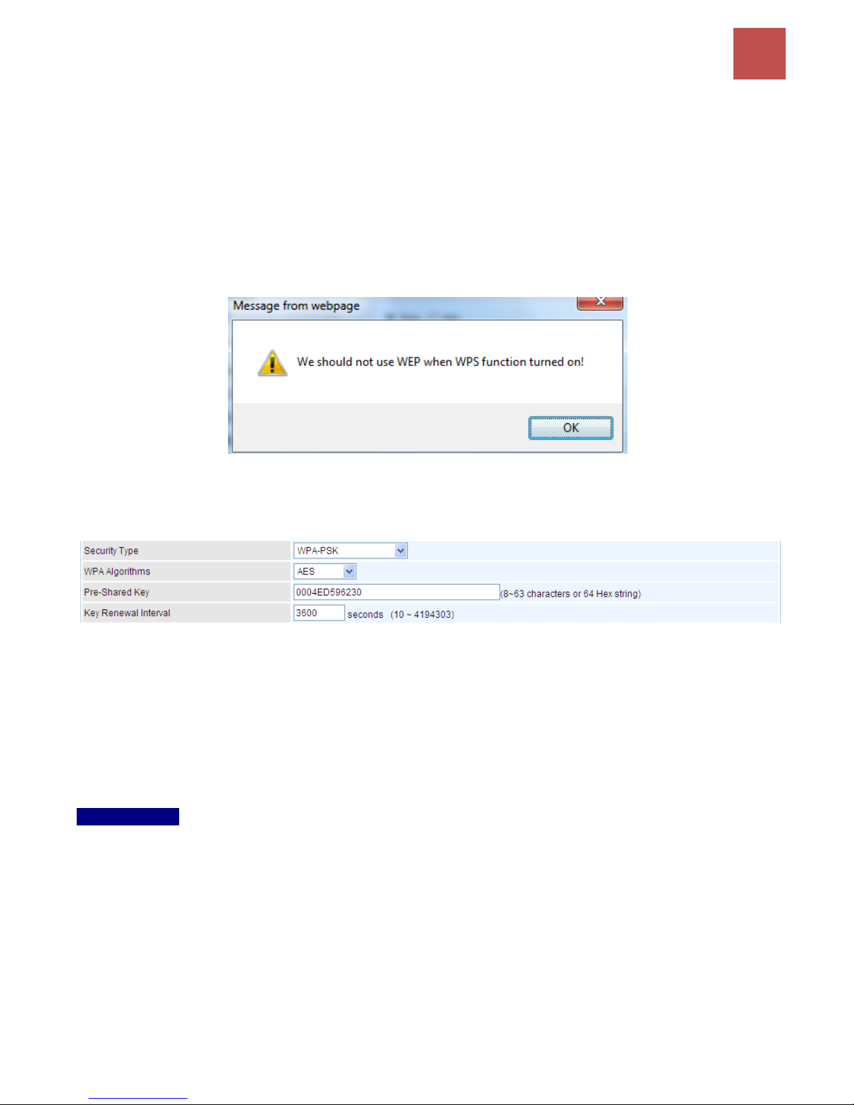
Note: When you enable WPS function, this WEP function will be invalid. And if you select one of
WEP-64Bits/ WEP-128Bits, the following prompt box will appear to notice you.
WPA-PSK & WPA2-PSK
WPA Algorithms: TKIP (Temporal Key Integrity Protocol) or AES (Advanced Encryption System)
utilizes a stronger encryption method and incorporates Message Integrity Code (MIC) to provide
protection against hackers.
Pre-Shared key: The key for network authentication. The input format should be 8-63 ASKII
characters or 64 hexadecimal characters
Key Renewal Interval: The time interval for changing the security key automatically between wireless
client and AP.
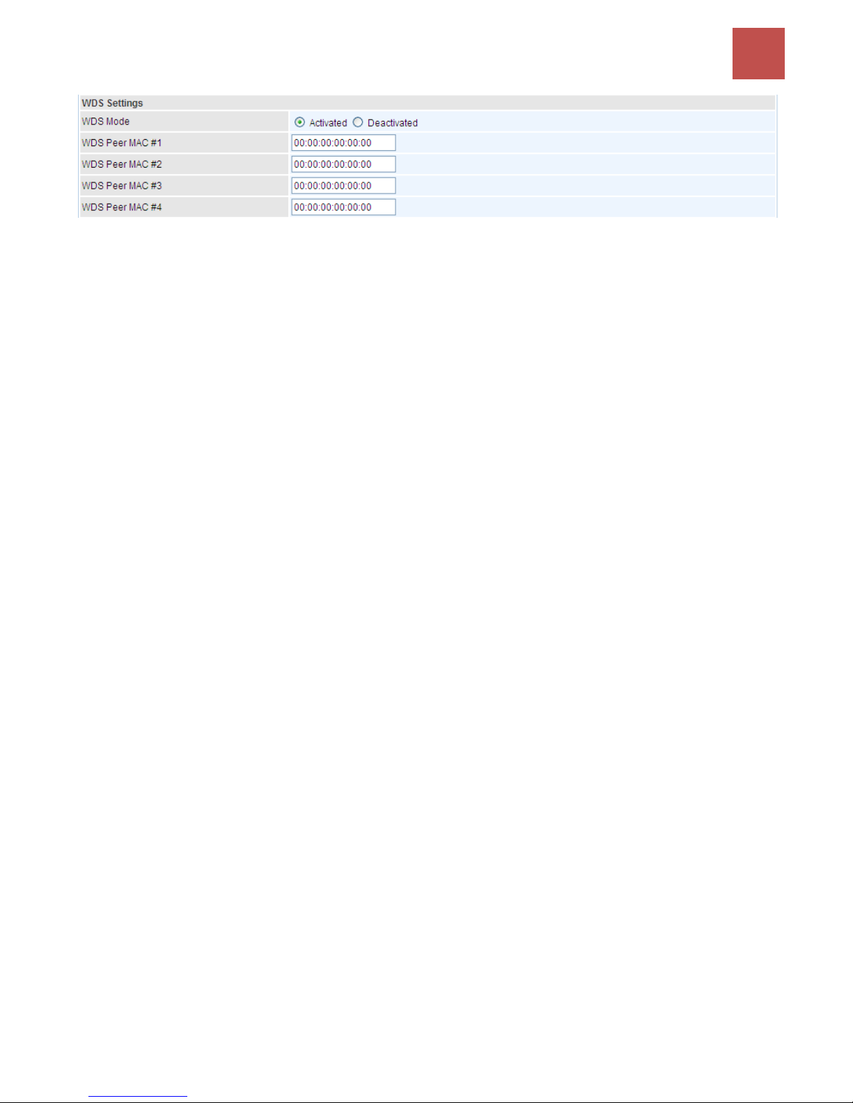
WDS Settings
WDS (Wireless distributed system) is a wireless access point mode that enables wireless link and
communication with other access point. It is easy to be installed, just define the peer’s MAC of the
connected AP.
WDS Mode: select Activated to enable WDS feature and Deactivated to disable this feature.
MAC Address: Enter the AP MAC addresses (in XX:XX:XX:XX:XX:XX format) of the peer connected
AP.
Page 64
Device Configuration /
Interface Setup
60
BEC 9800VN User Manual
Page 65
Device Configuration /
Interface Setup
61
BEC 9800VN User Manual
Wi-Fi Protected Setup (WPS) Example I:
PIN Method: Configure AP as Registrar
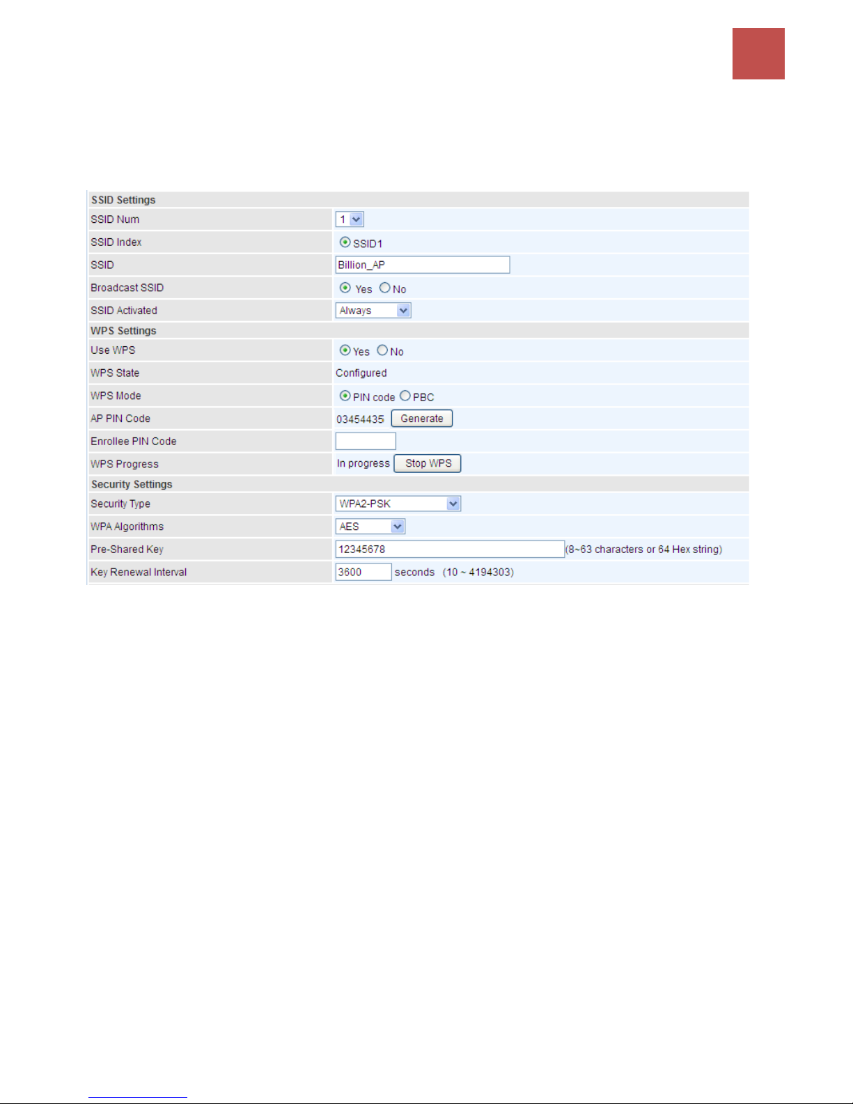
1. Jot down the client’s Pin (e.g. 04640776).
2. Enter the Enrollee (Client) PIN code and then press Start WPS.
Page 66
Device Configuration /
Interface Setup
62
BEC 9800VN User Manual
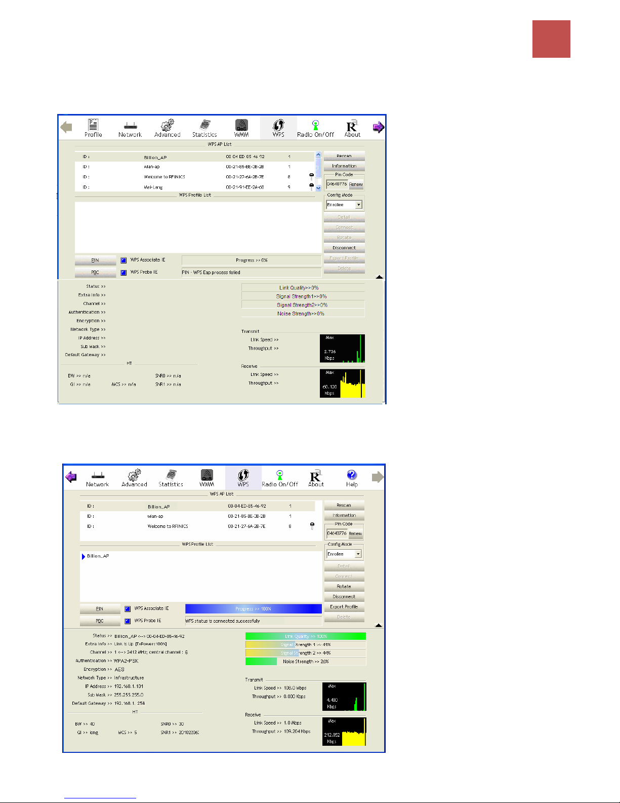
3. Launch the wireless client’s WPS utility (e.g. Ralink Utility). Set the Config Mode as Enrollee, press
the WPS button on the top bar, select the AP (e.g. Billion_AP) from the WPS AP List column. Then
press the PIN button located on the middle left of the page to run the scan.
4. The client’s SSID and security setting will now be configured to match the SSID and security setting
of the registrar (router).
Page 67
Device Configuration /
Interface Setup
63
BEC 9800VN User Manual
Wi-Fi Protected Setup (WPS) Example II:
PIN Method: Configure AP as Enrollee
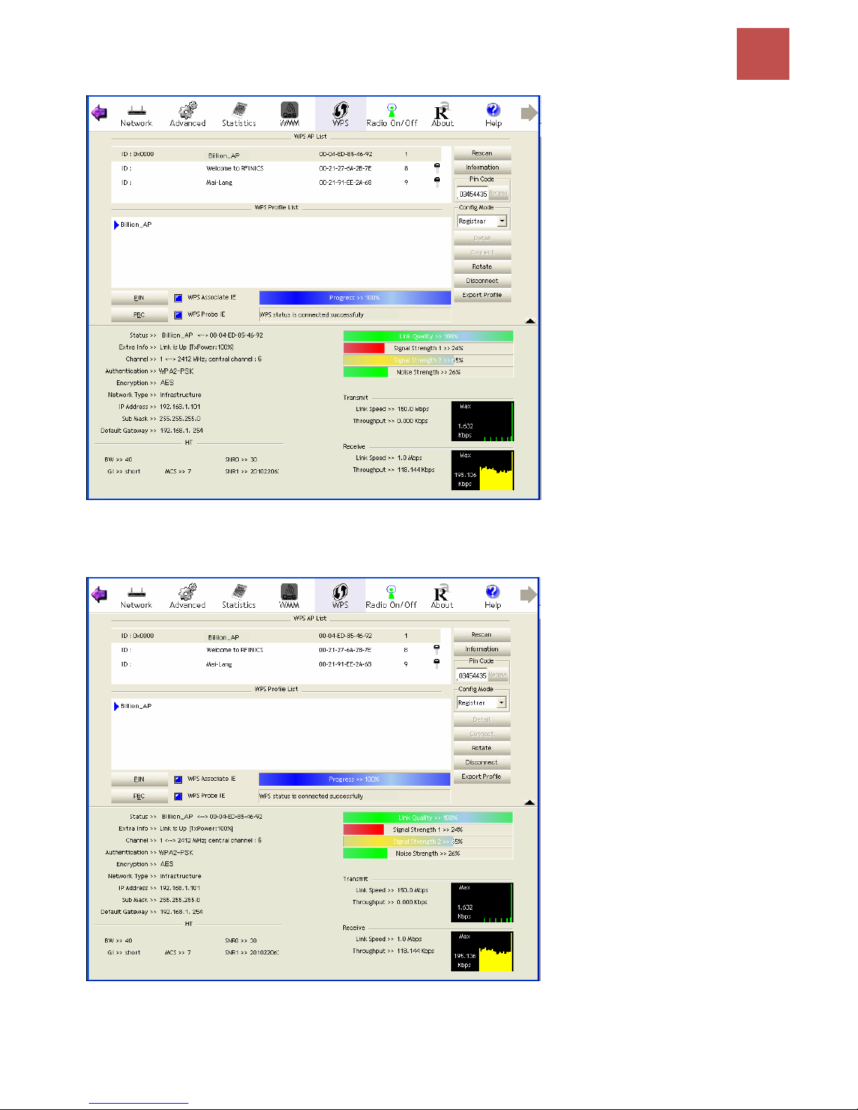
1. Jot down the WPS PIN (e.g. 03454435). Press Start WPS.
2. Launch the wireless client’s WPS utility (e.g. Ralink Utility). Set the Config Mode as Registrar. Enter
the PIN number in the PIN Code column then choose the correct AP (e.g. Billion_AP) from the WPS
AP List before pressing the PIN button to run the scan.
Page 68
Device Configuration /
Interface Setup
64
BEC 9800VN User Manual
3. The router’s (AP’s) SSID and security setting will now be configured to match the SSID and security
setting of the registrar (client).
4. Now to make sure that the setup is correctly done, cross check to see if the SSID and the security
setting of the registrar setting match with the parameters found on both Wireless Configuration and
Wireless Security Configuration page.
Page 69
Device Configuration /
Interface Setup
65
BEC 9800VN User Manual
Wi-Fi Protected Setup (WPS) Example III:
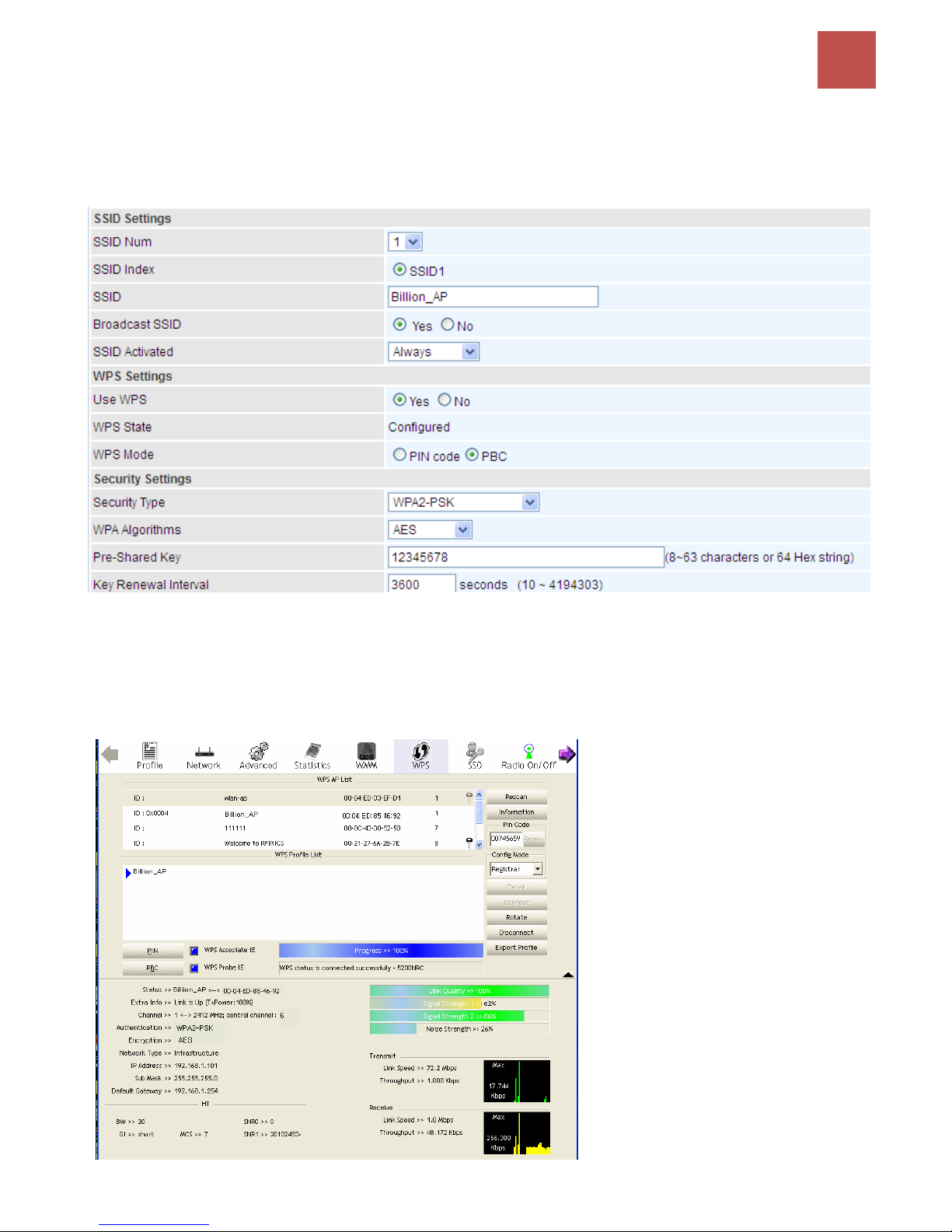
PBC Method:
1. Press the PBC radio button, Then Start WPS.
2. Launch the wireless client’s WPS Utility (e.g. Ralink Utility). Set the Config Mode as Enrollee. Then
press the WPS button and choose the correct AP (e.g. Billion_AP) from the WPS AP List section
before pressing the PBC button to run the scan.
3. When the PBC button is pushed, a wireless communication will be established between your router
and the PC. The client’s SSID and security setting will now be configured to match the SSID and
security setting of the router.
Page 70
Device Configuration /
Interface Setup
66
BEC 9800VN User Manual
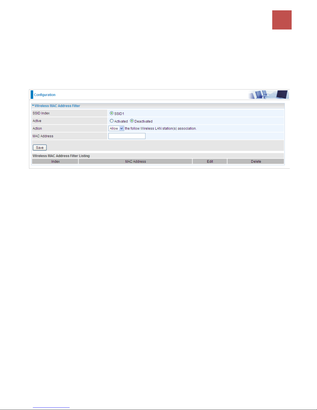
Wireless MAC Filter
The MAC filter screen allows you to configure the router to give exclusive access to up to 8 devices
(Allow Association) or exclude up to 8 devices from accessing the router (Deny Association). Every
Ethernet device has a unique MAC (Media Access Control) address. The MAC address is assigned at
the factory and consists of six pairs of hexadecimal characters, for example, 00:AA:BB:00:00:02.
You need to know the MAC address of the devices you wish to filter.
SSID Index: Select the targeted SSID you want the MAC filter rules to apply to.
Active: Select Activated to enable MAC address filtering.
Action: Define the filter action for the list of MAC addresses in the MAC address filter table.
Select Deny to block access to the AP, MAC addresses not listed will be allowed to access the router.
Select Allow to permit access to the router, MAC addresses not listed will be denied access to the
router.
MAC Address: Enter the MAC addresses (in XX:XX:XX:XX:XX:XX format) of the wireless station that
are allowed or denied access to the specified in these address fields.
Page 71
Device Configuration /
Dual WAN
67
BEC 9800VN User Manual
Dual WAN
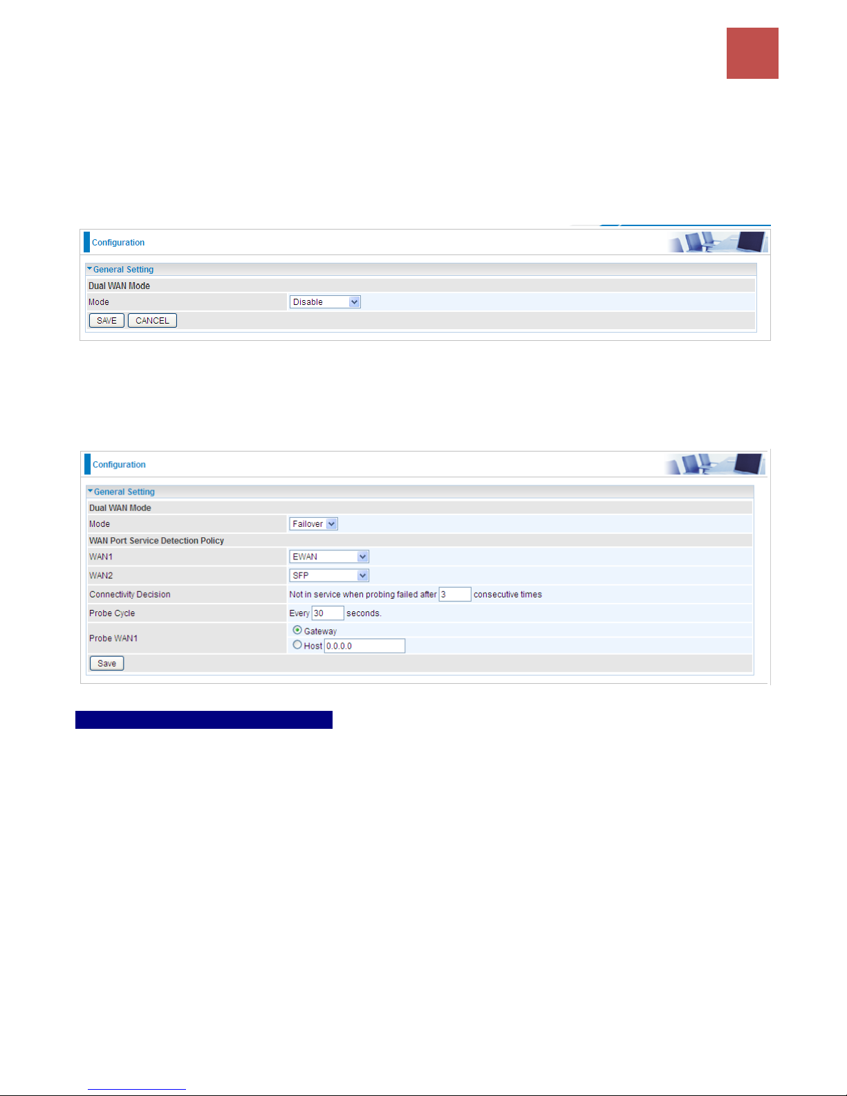
Dual WAN is specially designed to offer users Failover/Fallback or Load Balance feature.
Auto Failover/Failback is to ensure an always-on internet connection. Users can set a WAN1 (main
WAN) and WAN 2 (backup WAN), and when WAN1 fails, it will switch to WAN2, and when WAN1
restores, it will switch to WAN1 again.
Select Failover to enable the failover/failback feature or Load Balance to make the router work in load
balance mode.
Failover
WAN Port Service Detection Policy
WAN1: Select “EWAN” or “SFP” for WAN1 (The main WAN).
WAN2: Select“SFP” for WAN2 as backup port if you select “EWAN” as WAN1.
Connectivity Decision: Set how many times of probing failure to switch to backup port.
Probe Cycle: Set the time duration for the Probe Cycle to determine when the router will switch to the
backup connection (backup port) once the main connection (main port) fails. For example, when set to
30 seconds, the probe will be conducted every 30 seconds.
Note:
1) The time set is for each probe cycle, but the decision to change to the backup port is determined by
Probe Cycle multiplied by connection Decision amount (e.g. From the image above it will be 30
seconds multiplied by 3 consecutive fails, the router will determine failover to WAN2 (backup port)).
2).The failback setting follow the same decision policy as the failover. For example, according to
settings above in the screenshot, the connection probe will be carried out every 30 seconds, and 3
consecutive times of probe success is found, the router will determine failback to WAN1 (main WAN).
Page 72

Device Configuration /
Dual WAN
68
BEC 9800VN User Manual
Probe WAN 1: Choose the probe policy, to probe gateway or host (users decide themselves)
Gateway: It will send ping packets to gateway of Wan1 interface and wait for response from it in
every “Probe Cycle” to check the connectivity of the gateway of WAN1 interface.
Host: It will send ping packets to specific host and wait for response in every “Probe Cycle”.
The host must be an IP address.
Page 73
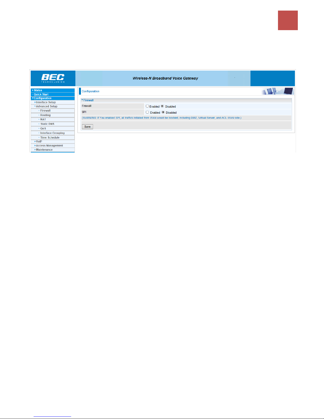
Device Configuration /
Advanced Setup
69
BEC 9800VN User Manual
Advanced Setup
Advanced Step provides advanced features including Firewall, Routing, NAT, Static DNS, QoS,
Port Isolation, Interface Grouping, and Time Schedule for advanced users.
Page 74
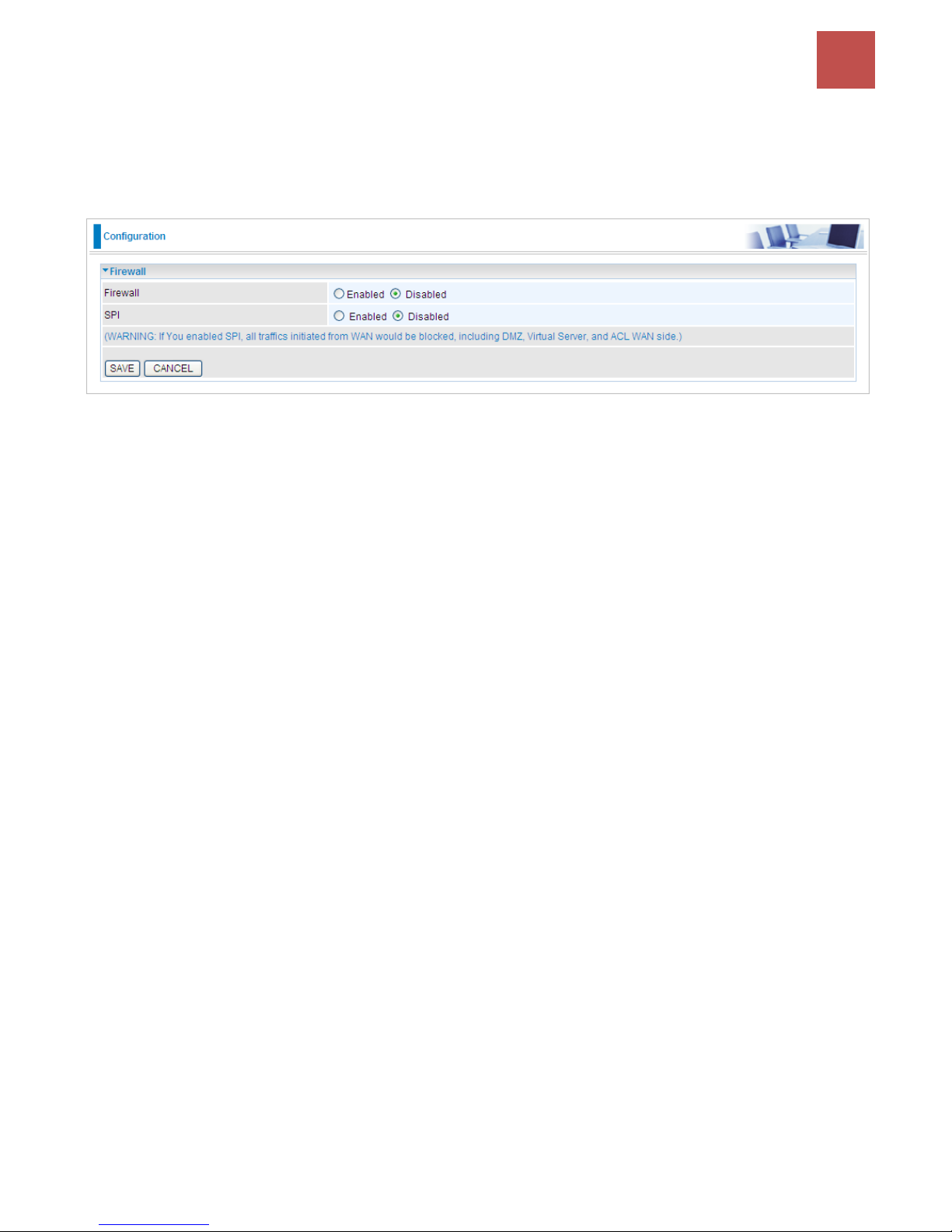
Device Configuration /
Advanced Setup
70
BEC 9800VN User Manual
Firewall
Your router includes a firewall for helping to prevent attacks from hackers. In addition to this, when
using NAT (Network Address Translation) the router acts as a “natural” Internet firewall, since all PCs
on your LAN use private IP addresses that cannot be directly accessed from the Internet.
Firewall: To automatically detect and block Denial of Service (DoS) attacks, such as Ping of Death,
SYN Flood, Port Scan and Land Attack.
Enabled: It activates your firewall function.
Disabled: It disables the firewall function.
SPI: If you enabled SPI, all traffics initiated from WAN would be blocked, including DMZ, Virtual Server,
and ACL WAN side.
Enabled: It activates your SPI function.
Disabled: It disables the SPI function.
Page 75
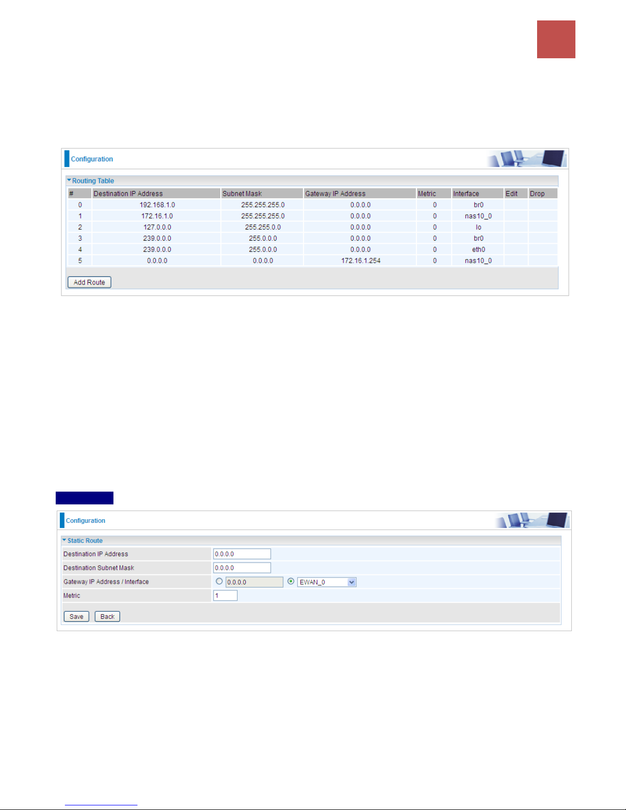
Device Configuration /
Advanced Setup
71
BEC 9800VN User Manual
Routing
This is static route feature. You are equipped with the capability to control the routing of all the traffic
across your network. With each routing rule created, user can specifically assign the destination where
the traffic will be routed to.
#: Item number
Destination IP Address: IP address of the destination network
Subnet Mask: The subnet mask of destination network.
Gateway IP Address: IP address of the gateway or existing interface that this route uses.
Metric: It represents the cost of transmission for routing purposes. The number need not be precise,
but it must be between 1 and 15.
Interface: Media/channel selected to append the route.
Edit: Edit the route; this icon is not shown for system default route.
Drop: Drop the route; this icon is not shown for system default route.
Add Route
Destination IP Address: This is the destination subnet IP address.
Destination Subnet Mask: The subnet mask of destination network.
Gateway IP Address/Interface: This is the gateway IP address or existing interface to which
packets are to be forwarded.
Metric: It represents the cost of transmission for routing purposes. The number need not be
precise, but it must be between 1 and 15.
Page 76
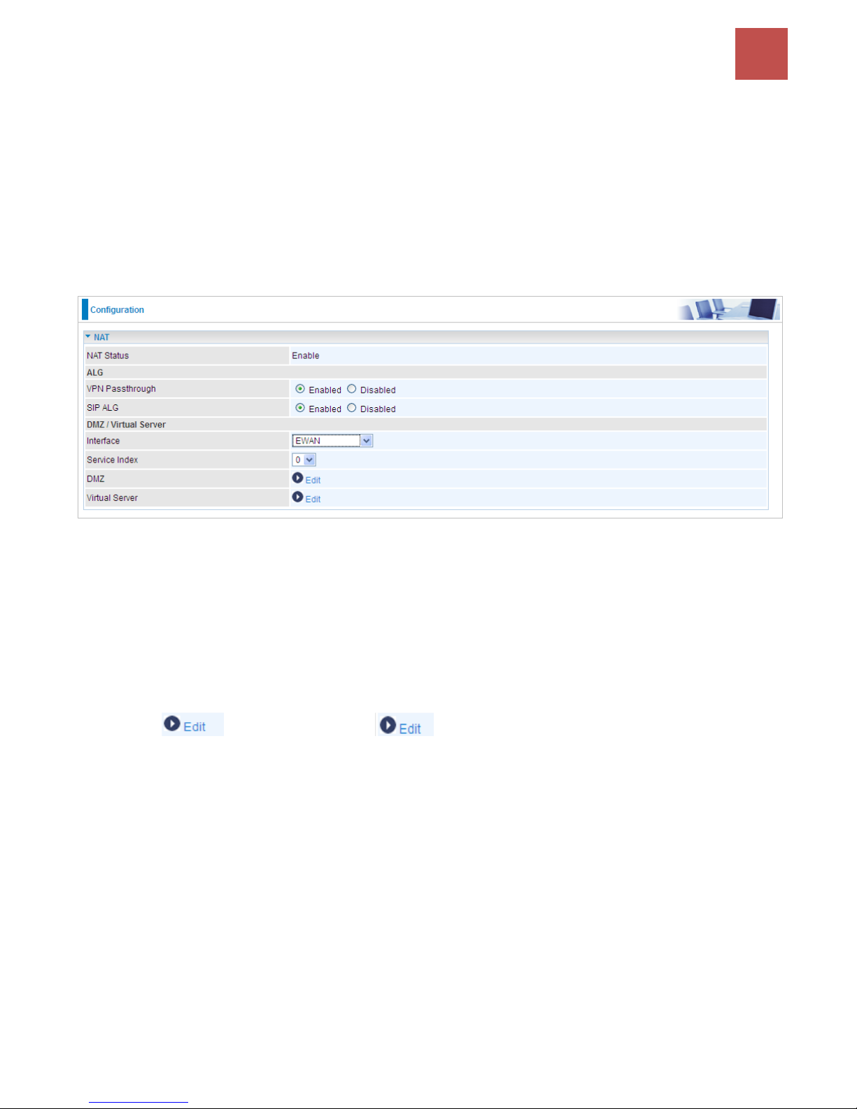
Device Configuration /
Advanced Setup
72
BEC 9800VN User Manual
NAT
The NAT (Network Address Translation) feature transforms a private IP into a public IP, allowing
multiple users to access the internet through a single IP account, sharing the single IP address. NAT
break the originally envisioned model of IP end-to-end connectivity across the internet so NAT can
cause problems where IPSec/ PPTP encryption is applied or some application layer protocols such as
SIP phones are located behind a NAT. And NAT makes it difficult for systems behind a NAT to accept
incoming communications.
In this session, there are “VPN Passthrough”, “SIP ALG”, “DMZ” and “Virtual Server” provided to solve
these nasty problems.
NAT Status: Enabled. It depends on ISP Connection Type in Internet settings.
VPN Passthrough: VPN pass-through is a feature of routers which allows VPN client on a private
network to establish outbound VPNs unhindered.
SIP ALG: Enable the SIP ALG when SIP phone needs ALG to pass through the NAT. Disable the SIP
ALG when SIP phone includes NAT-Traversal algorithm.
Interface: Select to set DMZ/Virtual Server for “EWAN”, “3G/4G-LTE” or “3G/4G-LTE USB”.
Service Index: Associated to EWAN interface marking each EWAN service (0-7), to select which
EWAN service the DMZ and Virtual server are applied to.
Click DMZ or Virtual Server to move on to set the DMZ or Virtual Server
parameters, which are represented in the following scenario.
Page 77
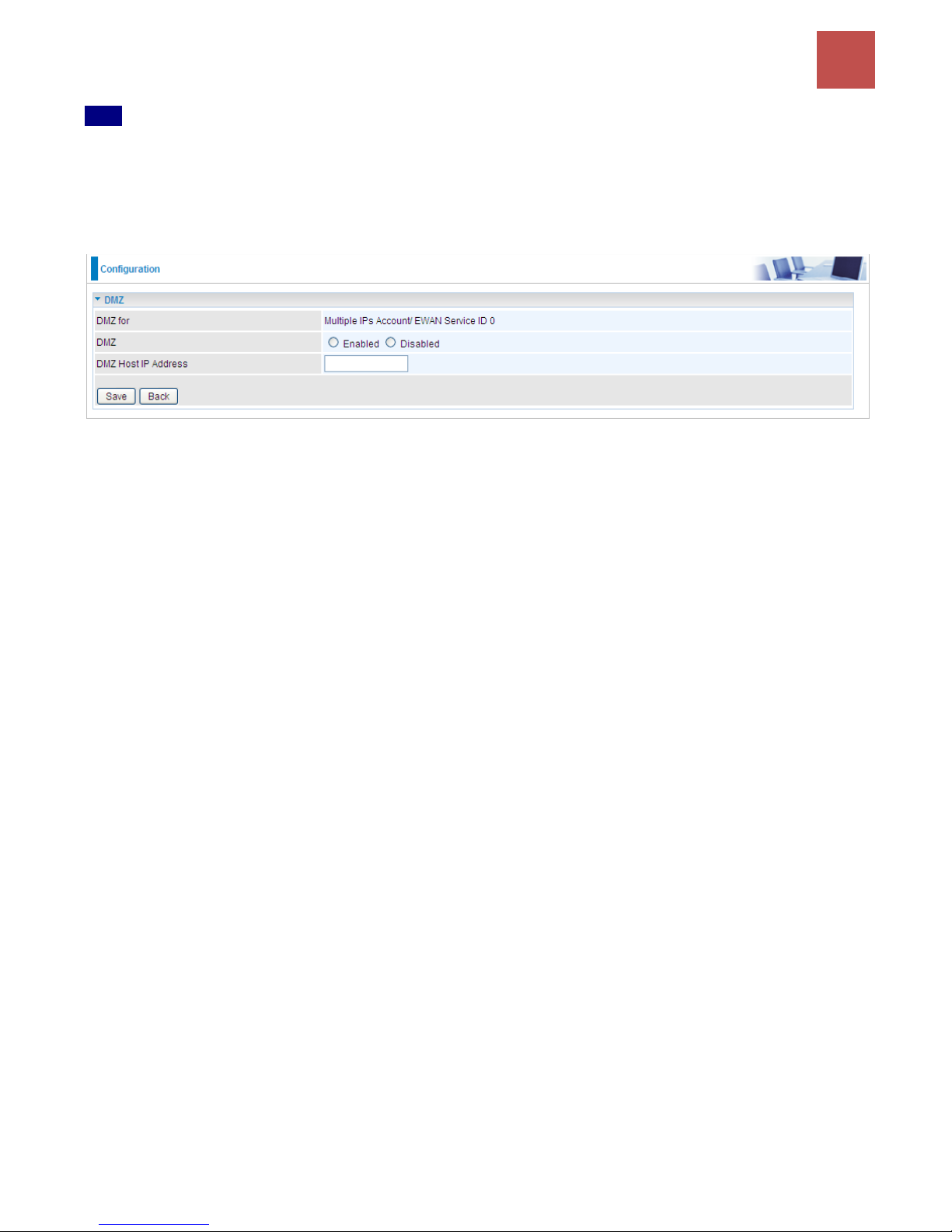
Device Configuration /
Advanced Setup
73
BEC 9800VN User Manual
DMZ
NOTE: This feature disables automatically if WAN connection is in BRIDGE mode.
The DMZ Host is a local computer exposed to the Internet. When setting a particular internal IP
address as the DMZ Host, all incoming packets will be checked by the Firewall and NAT algorithms
then passed to the DMZ host, when a packet received does not use a port number used by any other
Virtual Server entries.
DMZ for: Indicate the related WAN interface which allows outside network to connect in and
communicate. Note: Here you can see the Multiple IPs Account/EWAN Service ID 0. It is the interface
set in the previous NAT page.
DMZ:
Enabled: It activates your DMZ function.
Disabled: It disables the DMZ function.
DMZ Host IP Address: Give a static IP address to the DMZ Host when Enabled radio button is
checked. Be aware that this IP will be exposed to the WAN/Internet.
Select the Save button to apply your changes.
Page 78
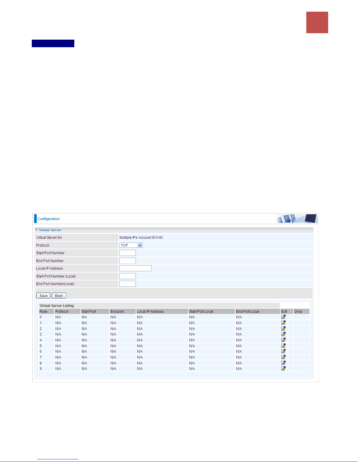
Device Configuration /
Advanced Setup
74
BEC 9800VN User Manual
Virtual Server
NOTE: This feature disables automatically if WAN connection is in BRIDGE mode.
In TCP/IP networks, a port is a 16-bit number used to identify which application program (usually a
server) incoming connections should be delivered to. Some ports have numbers that are pre-assigned
to them by the IANA (the Internet Assigned Numbers Authority), and these are referred to as
“well-known ports”. Servers follow the well-known port assignments so clients can locate them.
If you wish to run a server on your network that can be accessed from the WAN (i.e. from other
machines on the Internet that are outside your local network), or any application that can accept
incoming connections (e.g. Peer-to-peer/P2P software such as instant messaging applications and
P2P file-sharing applications) and are using NAT (Network Address Translation), then you will usually
need to configure your router to forward these incoming connection attempts using specific ports to the
PC on your network running the application. You will also need to use port forwarding if you want to
host an online game server.
The reason for this is that when using NAT, your publicly accessible IP address will be used by and
point to your router, which then needs to deliver all traffic to the private IP addresses used by your PCs.
Please see the WAN configuration section of this manual for more information on NAT.
The device can be configured as a virtual server so that remote users accessing services such as Web
or FTP services via the public (WAN) IP address can be automatically redirected to local servers in the
LAN network. Depending on the requested service (TCP/UDP port number), the device redirects the
external service request to the appropriate server within the LAN network.
Virtual Server for: Indicate the related WAN interface which allows outside network to connect in and
communicate.
Protocol: Choose the application protocol.
Start / End Port Number: Enter a port or port range you want to forward.
(Example: Start / End: 1000 or Start: 1000, End: 2000).
Page 79
Device Configuration /
Advanced Setup
75
BEC 9800VN User Manual
The starting greater than zero (0) and the ending port must be the same or larger than the starting port.
Local IP Address: Enter your server IP address in this field.
Start / End Port Number (Local): Enter the start / end port number of the local application (service).
Examples of well-known and registered port numbers are shown below. For further information, please
see IANA’s website at http://www.iana.org/assignments/port-numbers
Well-known and Registered Ports
Port Number
Protocol
Description
21
TCP
FTP Control
22
TCP & UDP
SSH Remote Login Protocol
23
TCP
Telnet
25
TCP
SMTP (Simple Mail Transfer Protocol)
53
TCP & UDP
DNS (Domain Name Server)
69
UDP
TFTP (Trivial File Transfer Protocol)
80
TCP
World Wide Web HTTP
110
TCP
POP3 (Post Office Protocol Version 3)
443
TCP & UDP
HTTPS
1503
TCP
T.120
1720
TCP
H.323
7070
UDP
RealAudio
Using port forwarding does have security implications, as outside users will be
able to connect to PCs on your network. For this reason you are advised to use
specific Virtual Server entries just for the ports your application requires,
instead of using DMZ. As doing so will result in all connections from the WAN
attempt to access to your public IP of the DMZ PC specified.
If you have disabled the NAT option in the WAN-ISP section, the Virtual Server
function will hence be invalid.
If the DHCP server option is enabled, you have to be very careful in assigning
the IP addresses of the virtual servers in order to avoid conflicts. The easiest
way of configuring Virtual Servers is to manually assign static IP address to
each virtual server PC, with an address that does not fall into the range of IP
addresses that are to be issued by the DHCP server. You can configure the
virtual server IP address manually, but it must still be in the same subnet as the
router.
Attention
Page 80
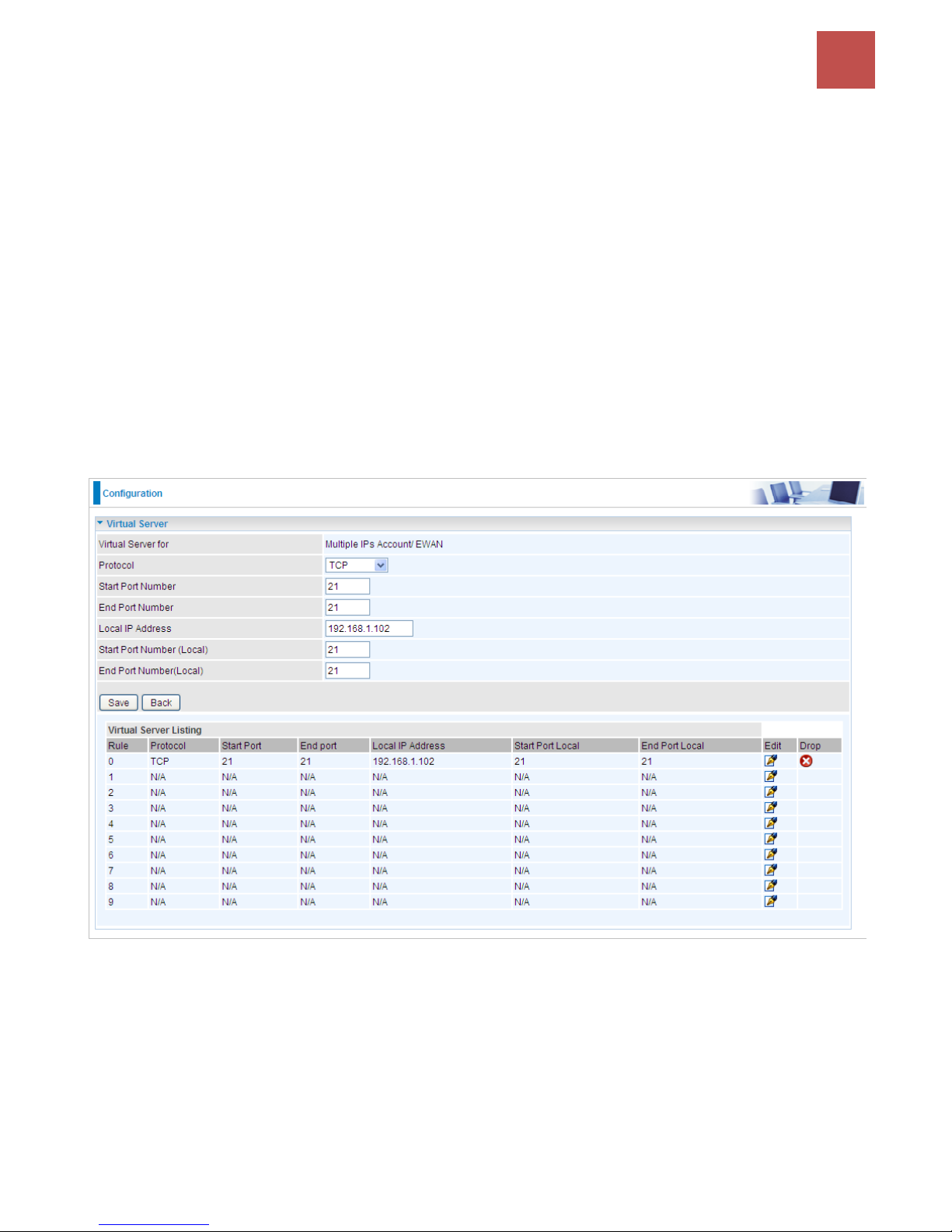
Device Configuration /
Advanced Setup
76
BEC 9800VN User Manual
Example : How to setup Port Forwarding for port 21 (FTP server)
If you have a FTP server in your LAN network and want others to access it through WAN.
Step 1: Assign a static IP to your local computer that is hosting the FTP server.
Step 2: Login to the Gateway and go to Configuration / Advanced Setup / NAT / Virtual Server.
FTP server uses TCP protocol with port 21.
Enter ”21” to Start and End Port Number. BEC 9800VN will accept port 21 requests from WAN side.
Eneter the static IP assiged to the local PC that is hosting the FTP server. Ex: 192.168.1.102
Enter ”21” to Local Start and End Port number. BEC 9800VN will forward port 21 request from WAN to
the specific LAN PC (ex:192.168.1.102) in the network.
Step 3: Click Save to save settings.
Page 81
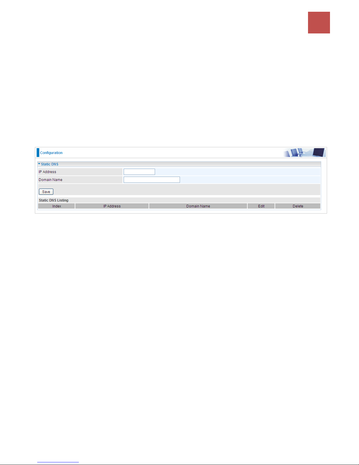
Device Configuration /
Advanced Setup
77
BEC 9800VN User Manual
Static DNS
The Domain Name System (DNS) is a hierarchical naming system built on a distributed database for
computers, services, or any resource connected to the Internet or a private network associates various
information with domain names assigned to each of the participating entities. Most importantly, it
translates domain names meaningful to humans into the numerical identifiers associated with
networking equipment for the purpose of locating and addressing these devices worldwide.
An often-used analogy to explain the Domain Name System is that it serves as the phone book for the
Internet by translating human-friendly computer hostnames into IP addresses. For example, the
domain name www.example.com can be translated into the addresses 192.0.32.10 (IPv4).
Static DNS is a concept relative to Dynamic DNS, in static DNS system, the IP mapped is static without
change.
IP Address: The IP address you are going to give a specific domain name.
Domain Name: The friendly domain name for the IP address.
Press Save button to apply your settings.
Page 82
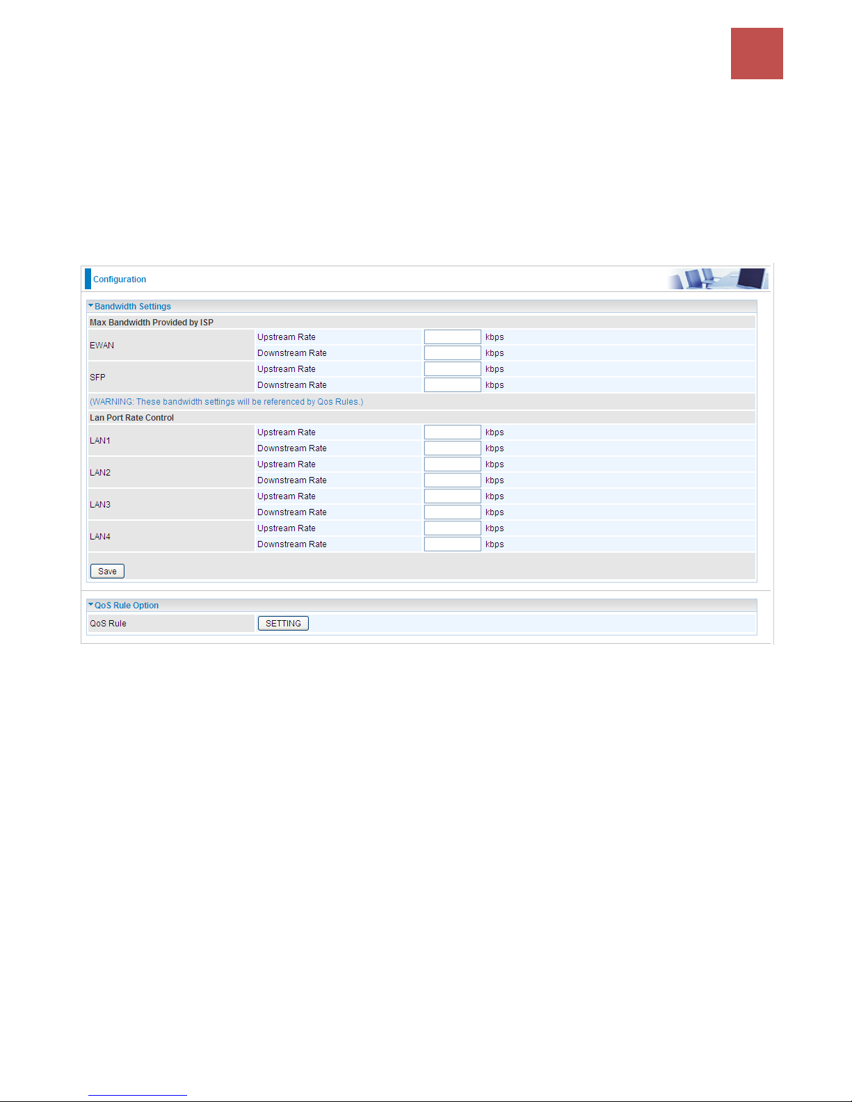
Device Configuration /
Advanced Setup
78
BEC 9800VN User Manual
QoS
QoS helps you control the upload traffic of each application from LAN (Ethernet and/or Wireless) to
WAN (Internet).
It facilitates you the features to control the quality of throughput for each application. This is useful
when there on certain types of data you want giver higher priority to, such as voice data packets given
higher priority than web data packets.
Note: EWAN/SFP line speed is based on the rate provided by ISP
EWAN Upstream / Downstream: Specify the upstream and downstream rate of the EWAN interface.
SFP Upstream / Downstream: Specify the upstream and downstream rate of the SFP interface.
LAN1-4 Upstream / Downstream: Specify the upstream and downstream rate of the LAN1-LAN4
interface.
Note: The above bandwidth(rate) settings will be taken as a reference by QoS rules.
Click Save to save the EWAN rate settings.
Click SETTING to add QoS rules (up to 32 QoS rules).
Page 83
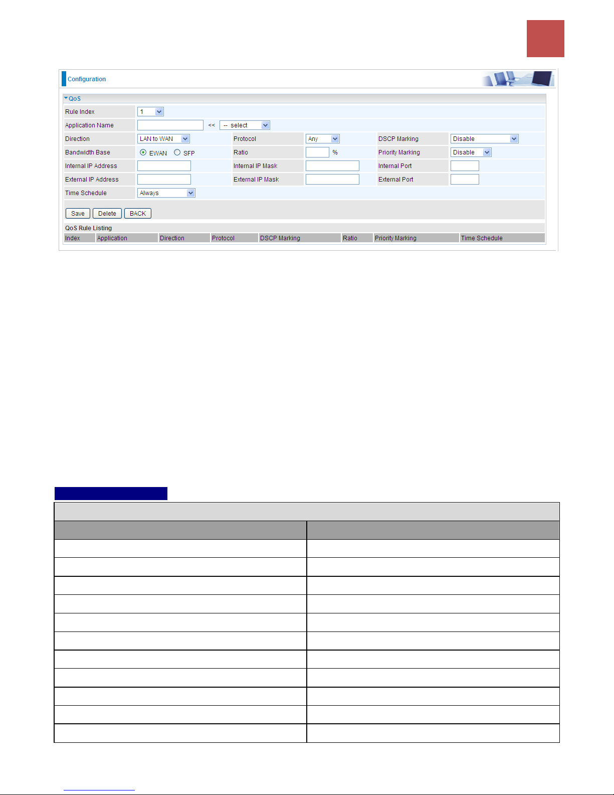
Device Configuration /
Advanced Setup
79
BEC 9800VN User Manual
Rule Index: Index marking for each rule up to maixmum of 32.
Application Name: Assign a name that identifies the new QoS application rule. Select from the list
box for quick setup.
Direction: Shows the direction mode of the QoS application.
LAN to WAN: You want to control the traffic from local network to the outside (Upstream). You
can assign the priority for the application or you can limit the rate of the application.
Ex: you have a FTP server inside the local network, and you want to have a limited control by
the QoS policy and so you need to add a policy with LAN to WAN direction setting.
WAN to LAN: Control traffic from WAN to LAN (Downstream).
Protocol: Select the supported protocol (Any, TCP, UDP, ICMP, GRE) from the drop down list.
DSCP Marking: Differentiated Services Code Point (DSCP), it is the first 6 bits in the ToS byte. DSCP
Marking allows users to classify the traffic of the application to be executed according to the DSCP
value.
DSCP Mapping Table
DSCP Mapping Table
(Wireless) ADSL Router
Standard DSCP
Disabled
None
Best Effort
Best Effort (000000)
Premium
Express Forwarding (101110)
Gold service (L)
Class 1, Gold (001010)
Gold service (M)
Class 1, Silver (001100)
Gold service (H)
Class 1, Bronze (001110)
Silver service (L)
Class 2, Gold (010010)
Silver service (M)
Class 2, Silver (010100)
Silver service (H)
Class 2, Bronze (010110)
Bronze service (L)
Class 3, Gold (011010)
Bronze service (M)
Class 3, Silver (011100)
Page 84
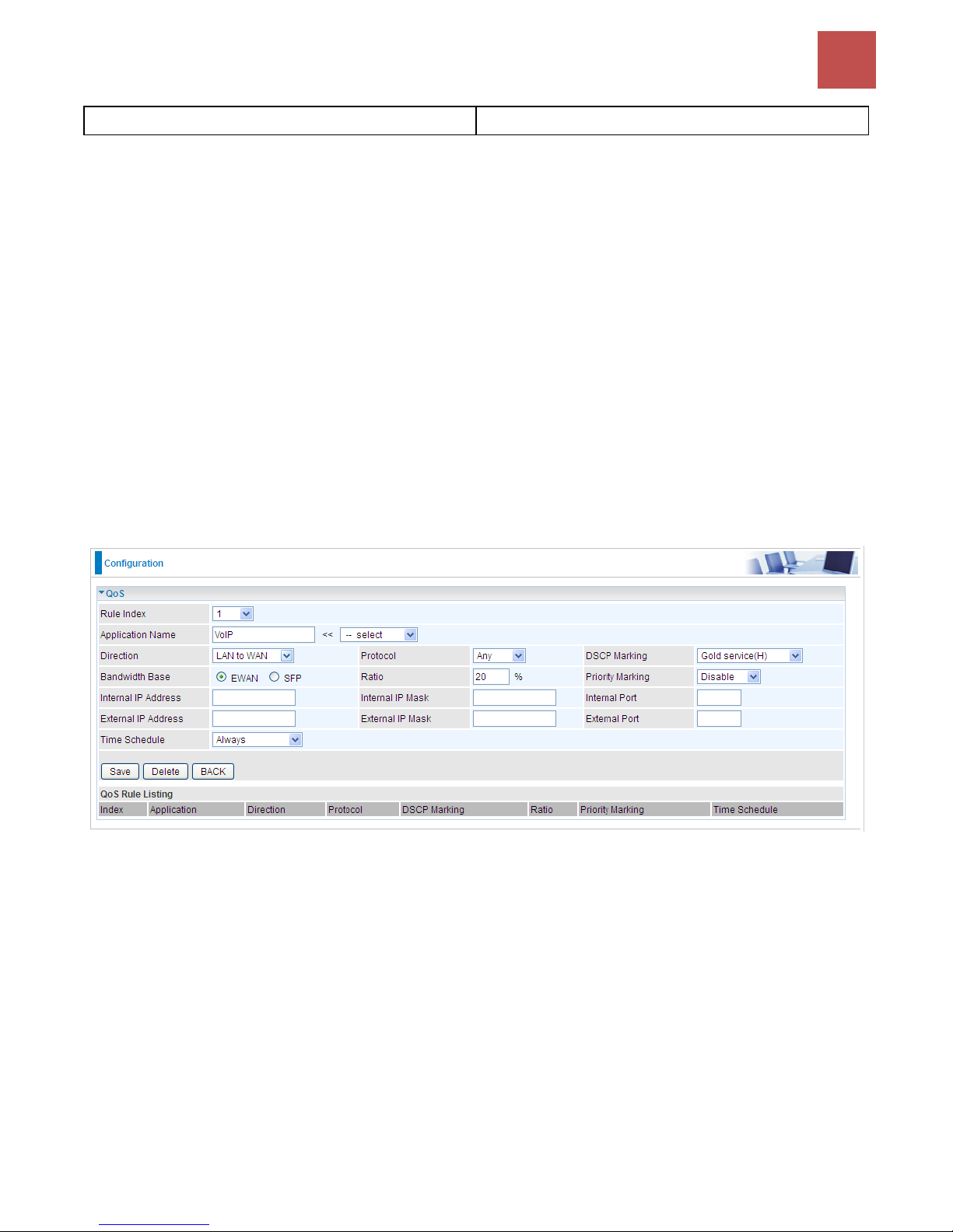
Device Configuration /
Advanced Setup
80
BEC 9800VN User Manual
Bronze service (H)
Class 3, Bronze (011110)
Bandwidth Base: Select SFP or EWAN as the bandwidth base whose upstream/downstream data
rate is pre-set in the previous page.
Ratio: The rate percent of each application/policy compared to total traffic on the interface. For
example, we want to only allow 20% of the total data ( note that the Bandwidth base, the ratio is based
on the bandwidth base)for the LAN-to-WAN direction to be used for FTP server. Then we can specify
here with data ratio = 20.
Priority: Set the priority given to each policy/application. Specify the priority for the use of bandwidth.
You can specify which application can have higher priority to acquire the bandwidth. You may adjust
this setting to fit your policy / application.
Internal IP Address: The IP address values for Local LAN devices you want to give control.
Internal Port: The Port number on the LAN side, it is used to identify an application.
External IP Address: The IP address on remote / WAN side.
External Port: The Port number on the remote / WAN side.
Time Schedule: Select or set exactly when the rule works..
For example, you can give outgoing VoIP traffic more bandwidth to ensure the quality of
bandwidth-sensitive audio service.
Page 85
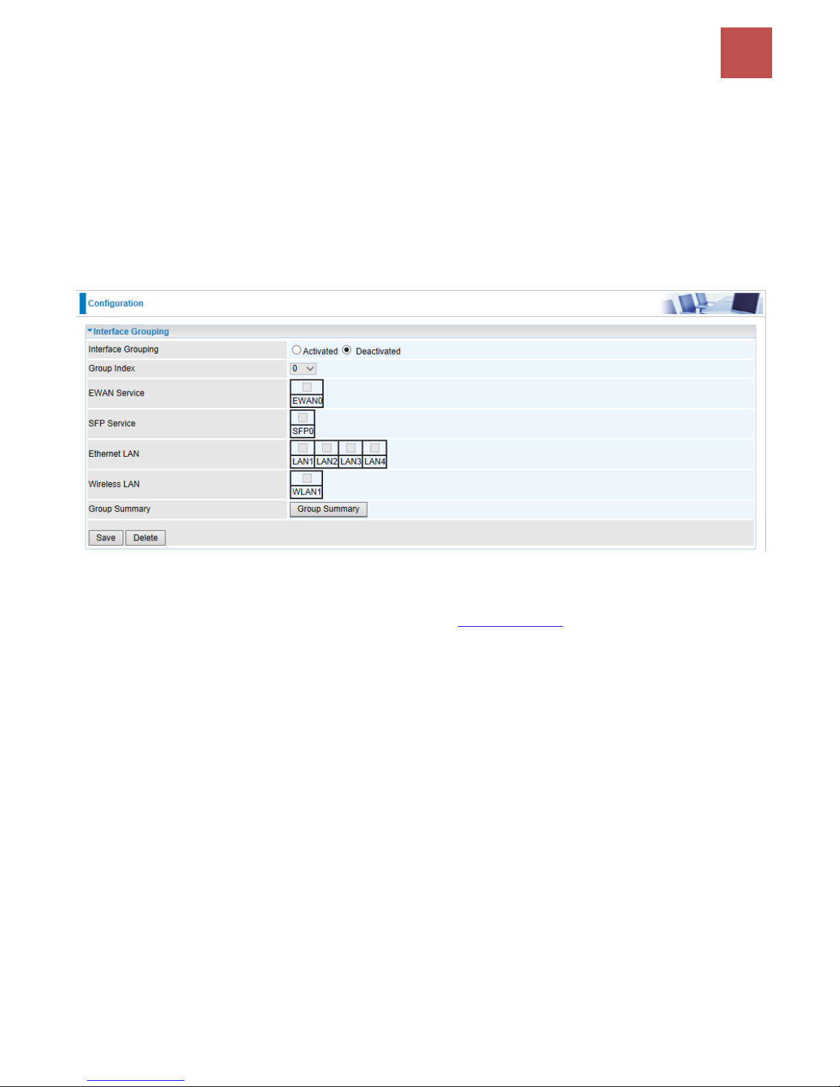
Device Configuration /
Advanced Setup
81
BEC 9800VN User Manual
Interface Grouping
Interface grouping is a function to group interfaces, known as VLAN. A Virtual LAN, commonly known
as a VLAN, is a group of hosts with the common set of requirements that communicate as if they were
attached to the same broadcast domain, regardless of the physical location. A VLAN has the same
attributes as a physical LAN, but it allows for end stations to be grouped together even if they are not
located on the same network switch. Similarly, they may also have been split into two different groups,
even if they are on the same switch.
Each group will perform as an independent network. To support this feature, you must create mapping
groups with appropriate LAN and WAN interfaces using the Save button.
Interface Grouping: Select Yes to enable Interface Grouping feature.
Group Index: The index number indicating the current group ranging from 0 to 15.
EWAN Service: The available EWAN interface. Move to Interface Setup to add other EWAN interface.
SFP Service: The available SFP interface.
Ethernet LAN: The available Ethernet ports.
Wireless LAN: The available wireless port(s).
Group Summary: Press PortBinding Summary to check the current group information.
Page 86
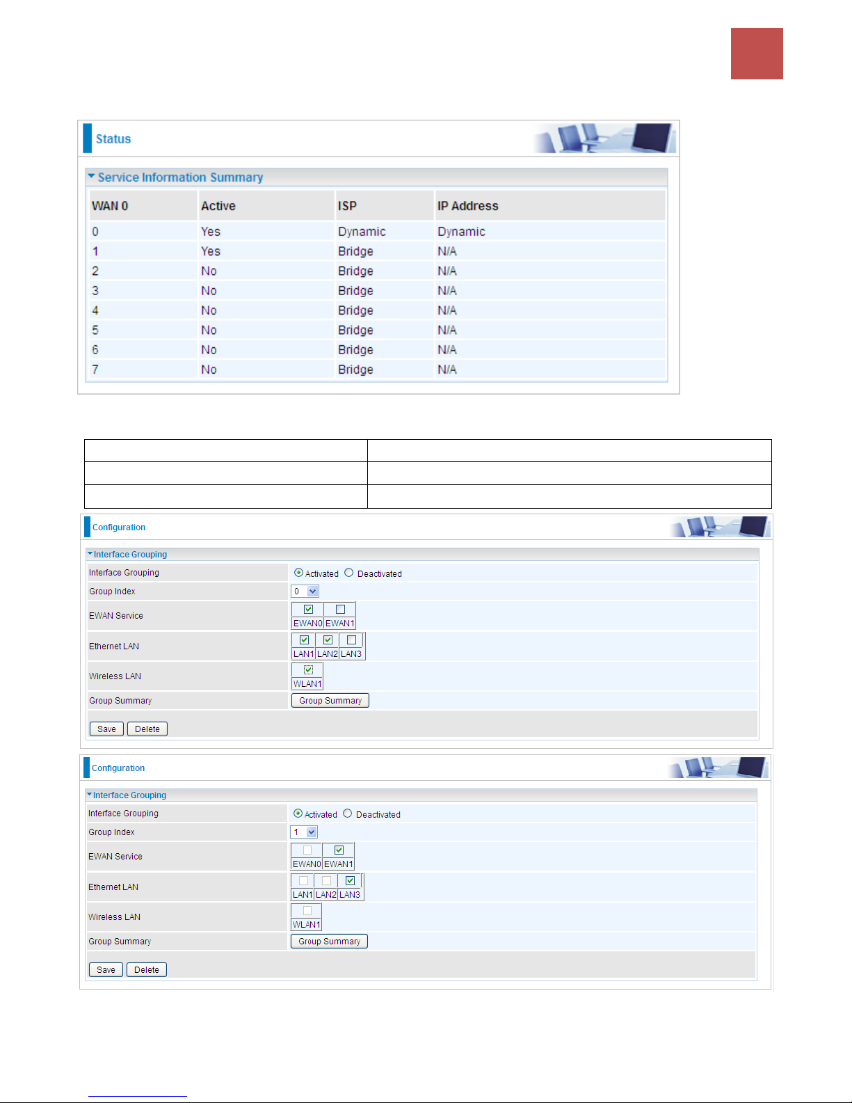
Device Configuration /
Advanced Setup
82
BEC 9800VN User Manual
Example: Create two EWAN services, Service0 (PPPoE) and Service1 (Bridge).
You are going to group the ports and services into two working group, as shown below.
Group Index
Group Port
0
EWAN0,LAN1, LAN2, WLAN1
1
EWAN1, LAN3
Click Group Summary to show the configuration results.
Page 87

Device Configuration /
Advanced Setup
83
BEC 9800VN User Manual
Page 88
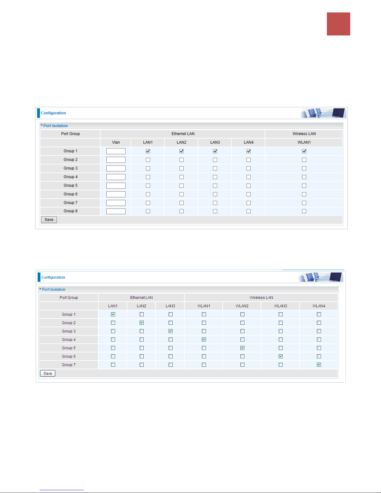
Device Configuration /
Advanced Setup
84
BEC 9800VN User Manual
Port Isolation
Port isolation is to prevent LAN (Wired or Wireless) devices, e.g. PC, Notebook, to associate or
communicate with each other devices. By default, all ports (LAN port and WLAN port) are sharing one
group, and devices in all these ports can have access to each other.
NOTE: The maximum WLAN (Wireless SSID) is up to 4. By default, only a SSID is being activated.
The most typical one example is to isolate all port from each other shown below. Each port has its own
group; under this circumstance, devices connected to each port have no access to other devices
connected to other ports. This is a special example, and users can change the settings to determine
how the ports are belonged to the group.
Page 89
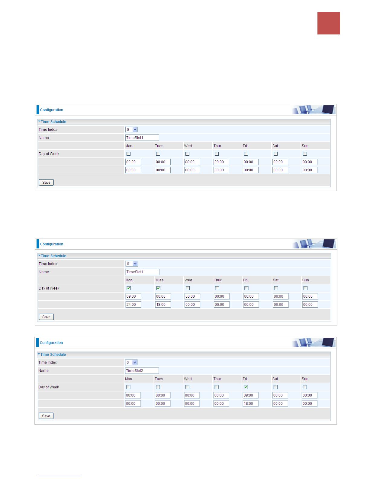
Device Configuration /
Advanced Setup
85
BEC 9800VN User Manual
Time Schedule
The Time Schedule supports up to 16 timeslots which helps you to manage your Internet connection.
In each time profile, you may schedule specific day(s) i.e. Monday through Sunday to restrict or
allowing the usage of the Internet by users or applications.
This Time Schedule correlates closely with router’s time, since router does not have a real time clock
on board; it uses the Simple Network Time Protocol (SNTP) to get the current time from an SNTP
server from the Internet.
Time Index: The rule index (0-15) for identifying each timeslot.
Name: User-defined identification for each time period.
Day of Week: Mon. to Sun. Specify the time interval for each timeslot from “Day of Week”. For
example, user can add a timeslot named “TimeSlot1” which features a period from 9:00 of Monday to
18:00 of Tuesday.
Another TimeSlot2 spanning from 09:00 to 18:00 of Friday
Page 90
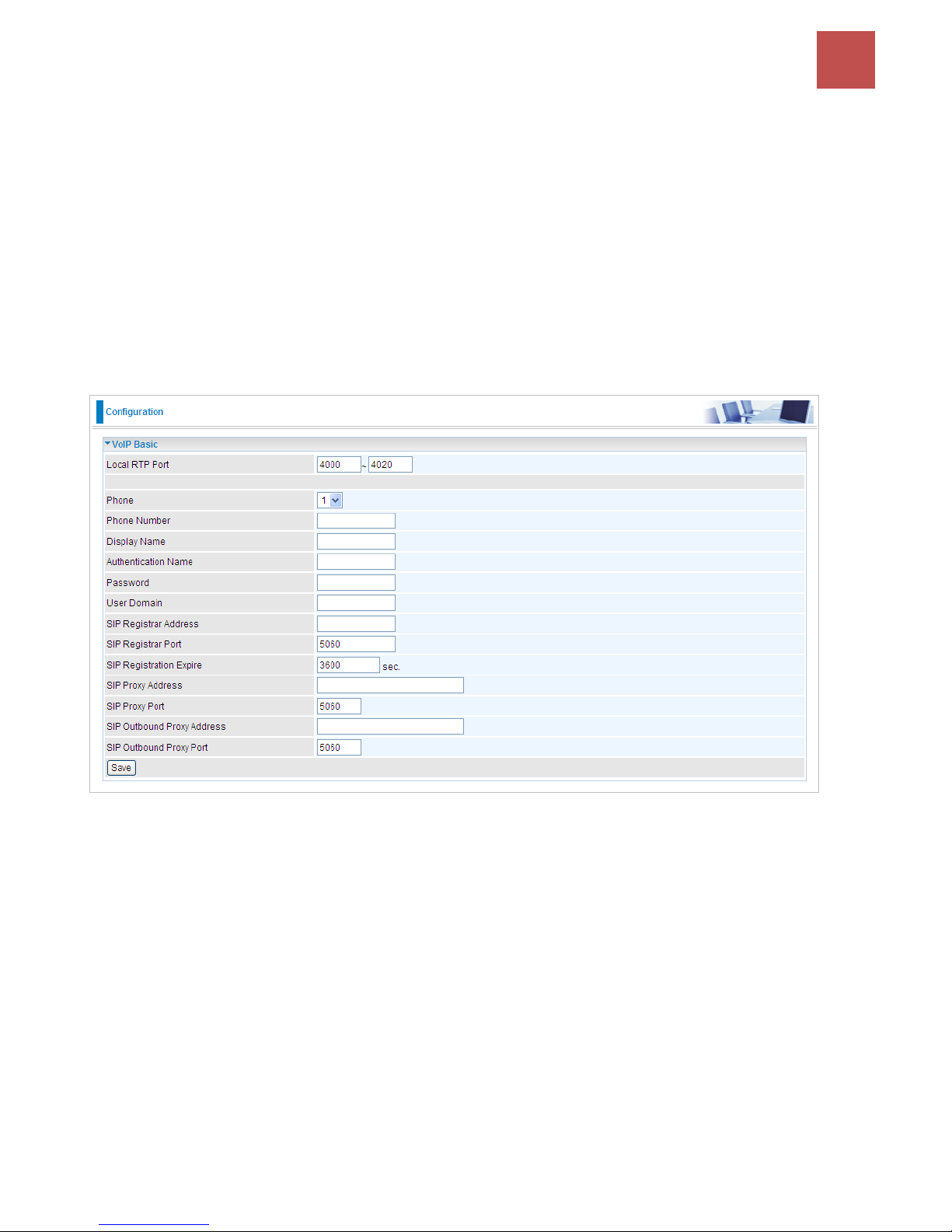
Device Configuration /
VoIP
86
BEC 9800VN User Manual
VoIP
VoIP, or Voice over Internet Protocol, enables telephone calls through existing internet connections
instead of going through the traditional PSTN (Public Switched Telephone Network). It is not only
cost-effective, especially for a long-distance call, but also top quality voice calls over the internet.
This section covers Basic, Media, Advanced, Speed Dial,and Call Features of VoIP.
Basic
Register to a SIP service provider is an essential step before making the VoIP call. You can find out
this information from your SIP service provider.
Locale RTP Port: Set the local RTP port range used to receive voice packet. This setting applies to
both the phone ports, Phone_1 and Phone_2, and these phone ports share the same local RTP port.
Phone: Select “1”, the following parameters will be applicable to Phone1. In BEC 9800VN, Phone_1
and Phone_2 are allowed to be of different characteristics, including different SIP registrar. You need
to configure individually for phone1 and phone 2 and can have up to 2 different VoIP accounts.
Phone Number: Set your phone number or outgoing call number, which is usually obtained when
registering in your ITSP. It is used for destination to identify which this call is made from.
Display Name: A user-friendly display name for the phone number to be easily identified.
Authentication Name: Set the account used to register, usually the Phone Number.
Password: Set the registering account password.
User Domain: Set the SIP Registrar Domain name you are going to register to, usually just the SIP
registrar address.
SIP Registrar Address: Enter the SIP registrar address where offers the service of registering the
VoIP account. It is definitely a VoIP server.
SIP Registrar Port: Type the port; it will listen to register requests from VoIP devices.
Page 91

Device Configuration /
VoIP
87
BEC 9800VN User Manual
SIP Registration Expire: Set the time interval. The device can update (usually re-login the account)
the VoIP account information with the SIP server very the time interval.
SIP Proxy Address: Enter the SIP proxy address provided by your ITSP. When destination and
source phones are not sharing the same SIP registrar domain, the SIP proxy is needed to deliver call
information and make the communication through.
SIP Proxy Port: Set the SIP proxy port.
SIP Outbound Proxy Address: Set the SIP outbound proxy address. It is usually used to realize the
communication between two phones when at least one of them is located behind a NAT router.
SIP Outbound Proxy Port: Set the SIP Outbound proxy port.
Page 92
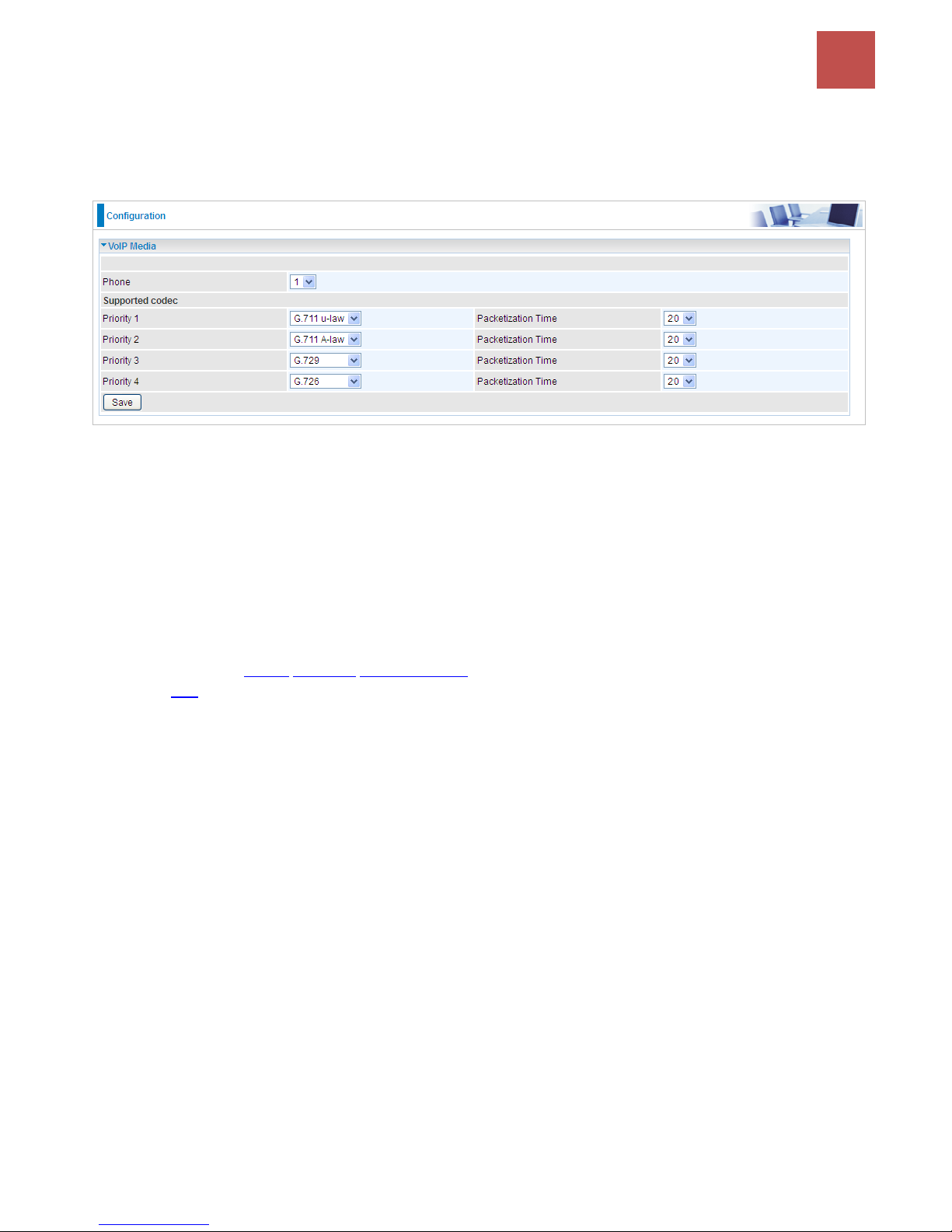
Device Configuration /
VoIP
88
BEC 9800VN User Manual
Media
Media offers for kinds of codec, G.711 u-law, G.711 A-law, G.729, G.726, from greatest to lowest in
priority.
Phone: Select to set the following configurations for Phone 1 or Phone2. When phone1 is selected,
the following set media codec will be applied to phone1.
G.711u-Law: It is a basic non-compressed encoder and decoder technique. μ-LAW uses pulse
code modulation (PCM) encoder and decoder to convert 14-bit linear sample.
G.711A-LAW: It is a basic non-compressed encoder and decoder technique. A-LAW uses
pulse code modulation (PCM) encoder and decoder to convert 13-bit linear sample into 8-bit
value.
G.729: It is used to encoder and decoder voice information into a single packet which reduces
the bandwidth consumption.
G.726: It is an ITU-T ADPCM speech codec standard covering the transmission of voice at rates
of 32kbit/s.
Page 93
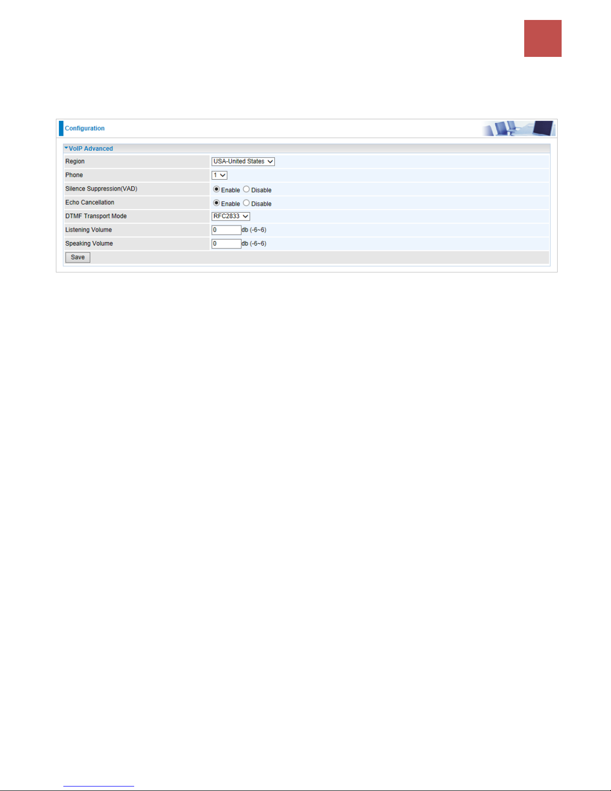
Device Configuration /
VoIP
89
BEC 9800VN User Manual
Advanced
Advance section equipment the users with the ability to do some advanced settings to each phone port.
Go on to see.
Region: Select the exact region from the drop-down menu to adjust the phone custom in the exact
region, like ring tone, busy tone, dial tone, etc, as different regions may have different phone using
traditions. The setting is to be applied to both phone 1 and phone 2.
Phone: Select the phone 1 or Phone 2 to have the following configurations applied to the phone.
Silence Suppression (VAD): Enable to minimize the use of bandwidth by automatically decreasing
transmission of background noise when the device detects on voice input by the user on the phone.
Echo Cancellation: Enable to cancel echo for the other side in communication so as to make a clear
listening environment. In order to avoid the other side in communication hearing the echo, please
enable echo cancellation.
DTMF Transport Mode: Select the DTMF mode.
Listening Volume: Adjust the volume of listener, -6 to 6, from lowest to highest.
Speaking Volume: Adjust the volume of microphone; -6 to 6, from lowest to highest.
Page 94
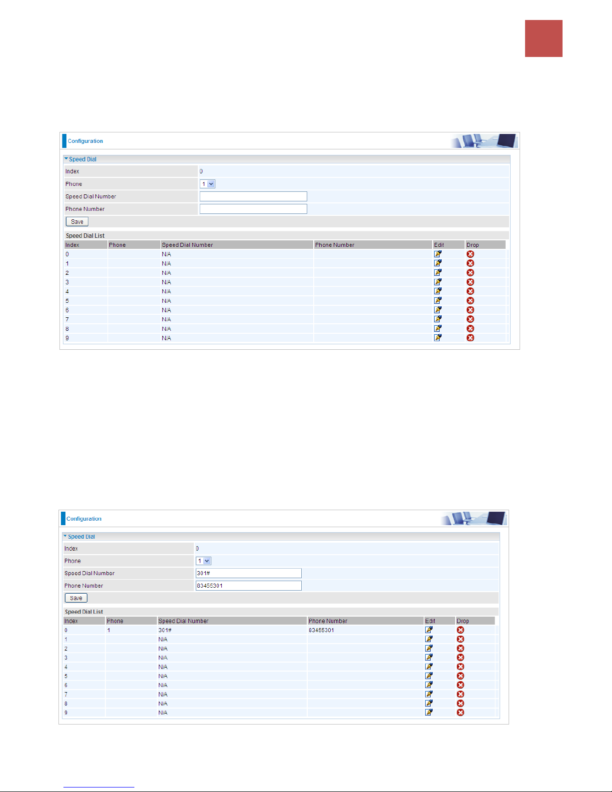
Device Configuration /
VoIP
90
BEC 9800VN User Manual
Speed Dial
Speed Dial comes at hand to store frequently used telephone number(s) that you can press set ‘speed
dial number’ instead of the exact dialing-out number on the phone keyboard to make a quick dialing.
Index: The index to mark the speed dial number mapping, 0-9.
Phone: Select Phone 1 or Phone 2 to have your set speed dial number applied to the phone. If phone
1 is selected, your set speed dial number is about to be applied to phone 1.
Speed Dial Number: Set an easily remembered and simple number to replace the Phone number, it
can be a sequence in varying length from 0, 1, 2, 3, 4, 5, 6, 7, 8, and 9 *. #, but note * or # must be
included in the sequence.
Phone Number: The complete destination number
Example: Save phone number 83455301 to the speed dial list.
When you want call 83455301 through phone 1, you can simply dial 301# to make your desired call.
Page 95
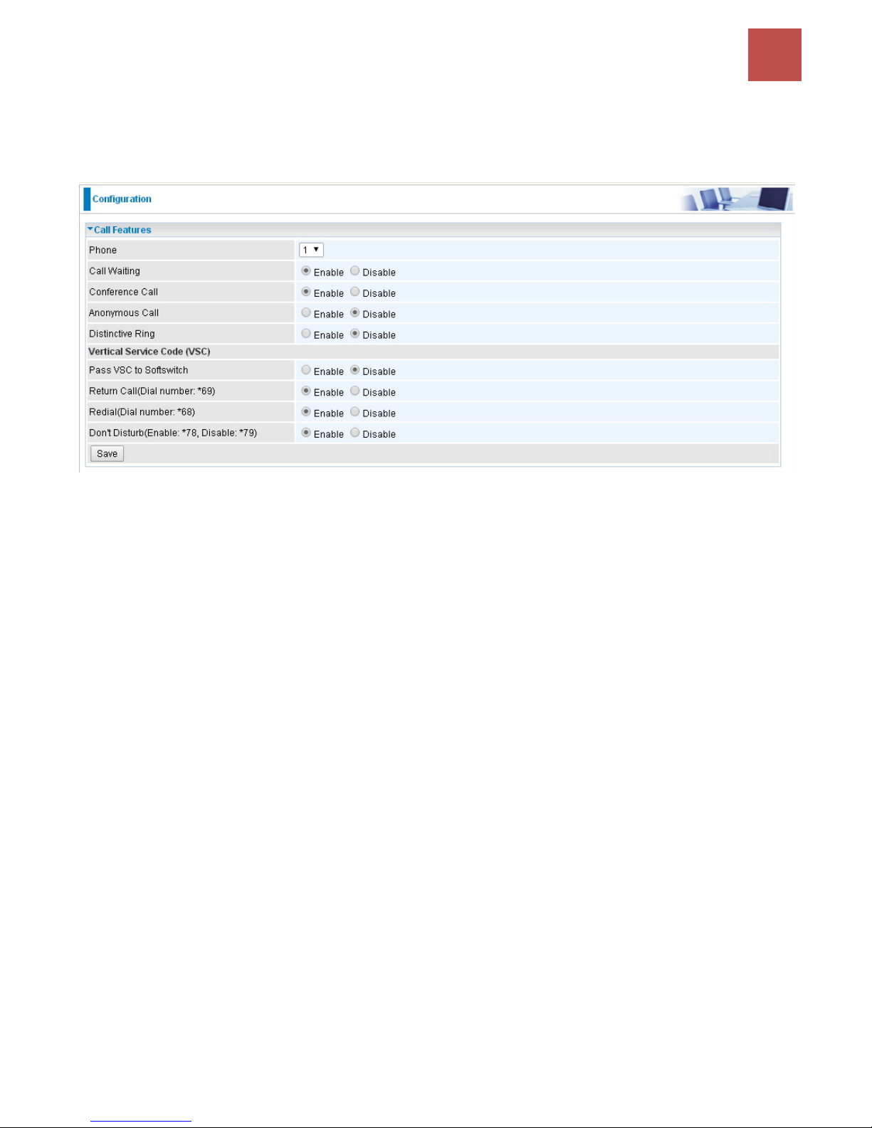
Device Configuration /
VoIP
91
BEC 9800VN User Manual
Call Features
Call Features provides users with some advanced phone characteristics, including Call waiting,
Conference Call, etc.
Phone: Select the phone 1 or Phone 2 to have the following characteristics applied to the phone.
Call Waiting: Enable to activate Call Waiting feature. When you are busy on a call with, for example, A,
and another call comes in, B, while the Call Waiting feature is enabled, you can hear a hint sound
indicating there is another call in for you to decide to answer B by pressing the “flash” button on the
phone to keep the original call with A.
Conference Call: Enable to allow 3-way conference call. Please note, only 3 parties are allowed
(device, A, and B).
Anonymous Call: This feature enables you to restrict your phone number from displaying to the
called party. When enabled, your phone number will be withheld and not be revealing to the called
party.
Distinctive Ring: This call feature is only available from a VoIP Service Provider which enables each
telephone number to have a distinctive ring sound.
Note: Before enabling this feature, please consult with your VoIP Service Provide to be sure it can be supported.
There is a ringtone list available in the BEC 9800VN, after enabling this feature, your BEC 9800VN will
adapt a specific ring pattern on the list requested by your VoIP Service Provider for a specific
telephone number.
When it is being disabled, all income calls will adapt the default ringtone for all telephone lines.
Pass VSC to Softswitch:
Enable to pass VSC(Vertical Service Code) to the SIP server of ITSP which allows the SIP
server to handle all its unique calling features such as Return Call, Call Redial, Don’t Disturb,
etc. Under this circumstance, users need to pay for such service, please ensure you check with
your SIP provider for more information.
Disable to let the BEC 9800VN to handle all available call features.
Return Call (Dial number: *69): Dial *69 to redial the latest incoming call number.
Redial (Dial number: *68): Dial *68 to redial the latest outgoing call number.
Don’t Disturb (Enable: *78, Disable: *79): Press *78 to enable Don’t Disturb feature so as to make it
Page 96

Device Configuration /
VoIP
92
BEC 9800VN User Manual
not ring when a call comes in; while press *79 to disable Don’t Disturb feature, if a call comes with a
ringing indication.
Page 97
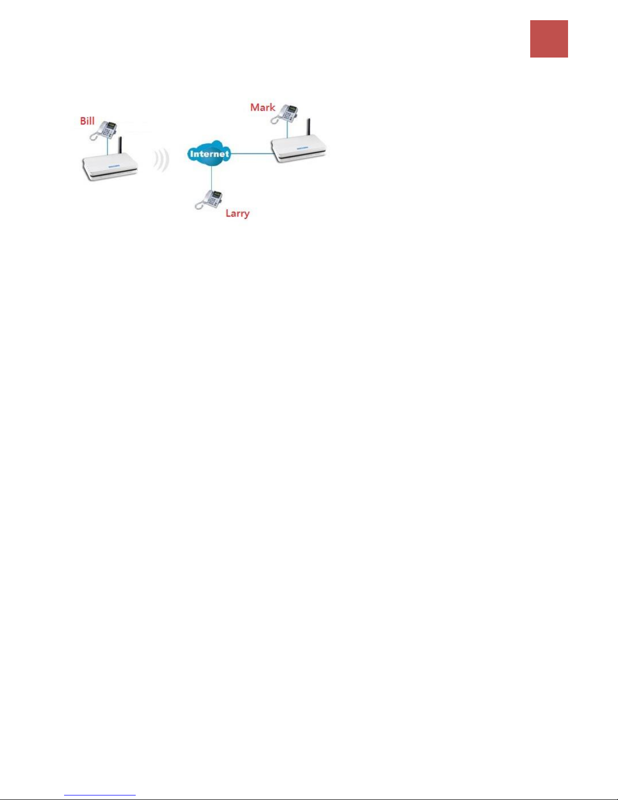
Device Configuration /
VoIP
93
BEC 9800VN User Manual
Example: How to establish 3-way conference call
Case 1: Bill and Larry are talking. Bill wants to invite Mark to join a conference call.
Step – 1: Billy and Larry are discussing on the phone. Bill tells Larry that he wants to set up a conference call
with Mark.
Step – 2: Bill presses flash (hold original call), and Bill hears the dial tone.
Step – 3: Bill calls Mark. Bill and Mark are on a new call.
Step – 4: Bill tells Mark that Mark is invited to join a conference call.
Step – 5: Bill presses flash (hold new call) and return to original call.
Step – 4: Bill tells Larry that Mark is on the phone.
Step – 6: Bill presses flash again to merge all 3 calls.
Step – 7: Bill, Larry and Mark hold a 3-way conference call from now on.
Case 2: When Bill and Larry are talking on the phone, Bill received a phone call from Mark. Bill decided
to ask Mark to join the conference call.
Step – 1: Bill and Larry on a call, then Mark dials Bill and Bill hears a waiting tone.
Step – 2: Bill presses flash and picks up the call waiting call.
Step – 3: Bill tells Mark that he and Larry are talking on the phone; they can have a conference call.
Step – 4: Bill presses flash to hold the call with Mark and return to original call with Larry.
Step – 5: Bill tells Larry that it is Mark and he wants to set up a conference with Mark.
Step – 6: Bill presses flash again to merge all 3 calls.
Step – 7: Bill, Larry and Mark hold a 3-way conference call from now on.
Page 98
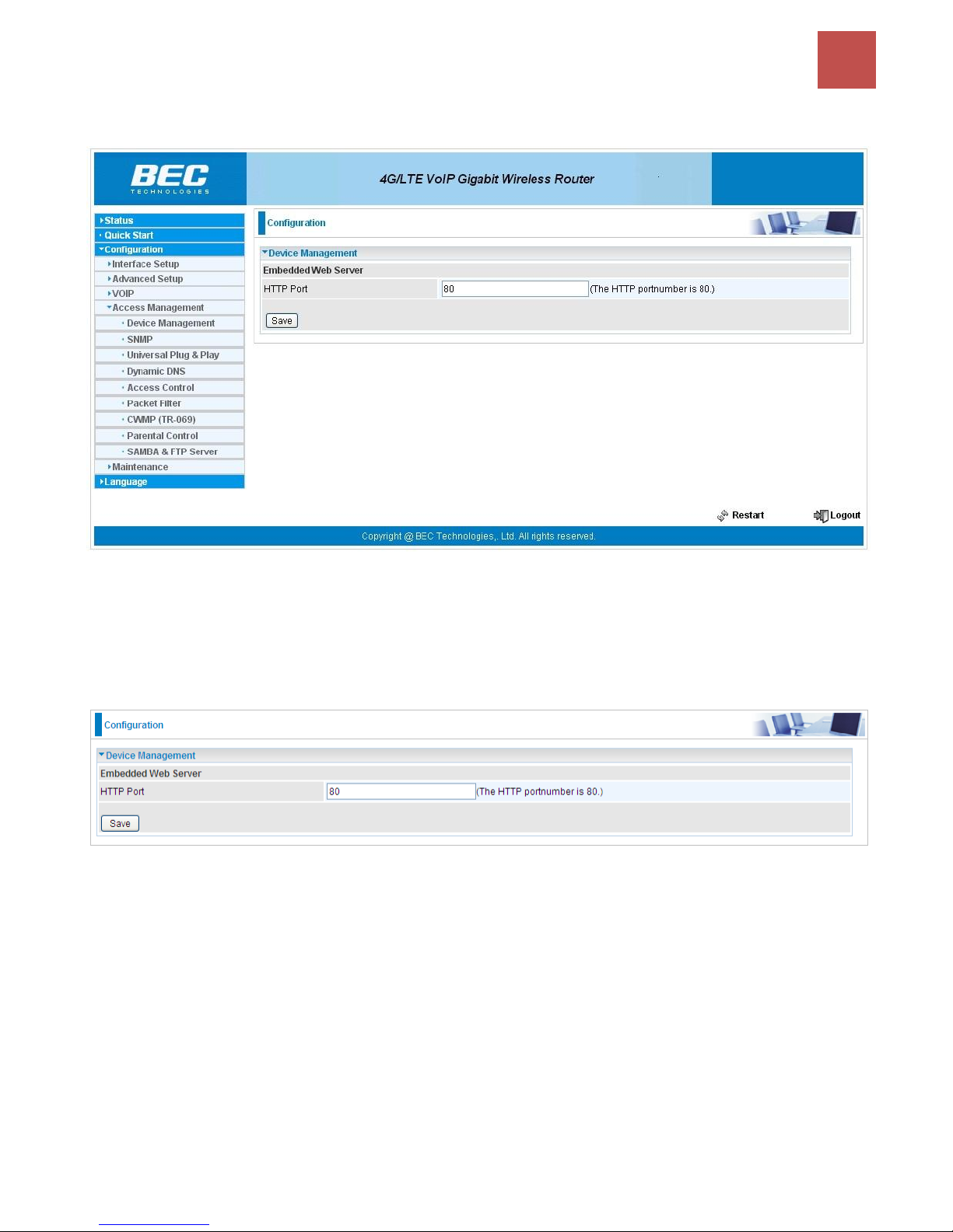
Device Configuration /
Access Management
94
BEC 9800VN User Manual
Access Management
Device Management
Device management offers users a way to change the embedded web server accessing port, default
80. User can change the http port to 8080 or something else here.
Page 99
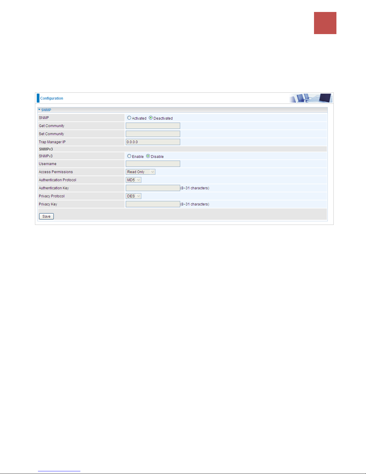
Device Configuration /
Access Management
95
BEC 9800VN User Manual
SNMP
Simple Network Management Protocol (SNMP) is a protocol used for exchanging management
information between network devices. SNMP is a member of the TCP/IP protocol suite. BEC 9800VN
serves as a SNMP agent which allows a manager station to manage and monitor the router through
the network.
SNMP: Select to enable SNMP feature.
Get Community: Type the Get Community, which is the password for the incoming Get-and-GetNext
requests from the management station.
Set Community: Type the Set Community, which is the password for incoming Set requests from the
management station.
Trap Manager IP: Enter the IP of the server receiving the trap message (when some exception occurs)
sent by this SNMP agent.
SNMPv3: Enable to activate the SNMPv3.
User Name: Enter the name allowed to access the SNMP agent.
Access Permissions: Set the access permissions for the user; RO--read only and RW--read and
writer.
Authentication Protocol: Select the authentication protocol, MD5 and SHA. SNMP agent can
communicate with the manager station through authentication and encryption to secure the message
exchange. Set the authentication and encryption information here and below.
Authentication Key: Set the authentication key, 8-31 characters.
Privacy Protocol: Select the privacy mode, DES and AES.
Privacy Key: Set the privacy key, 8-31 characters.
Page 100
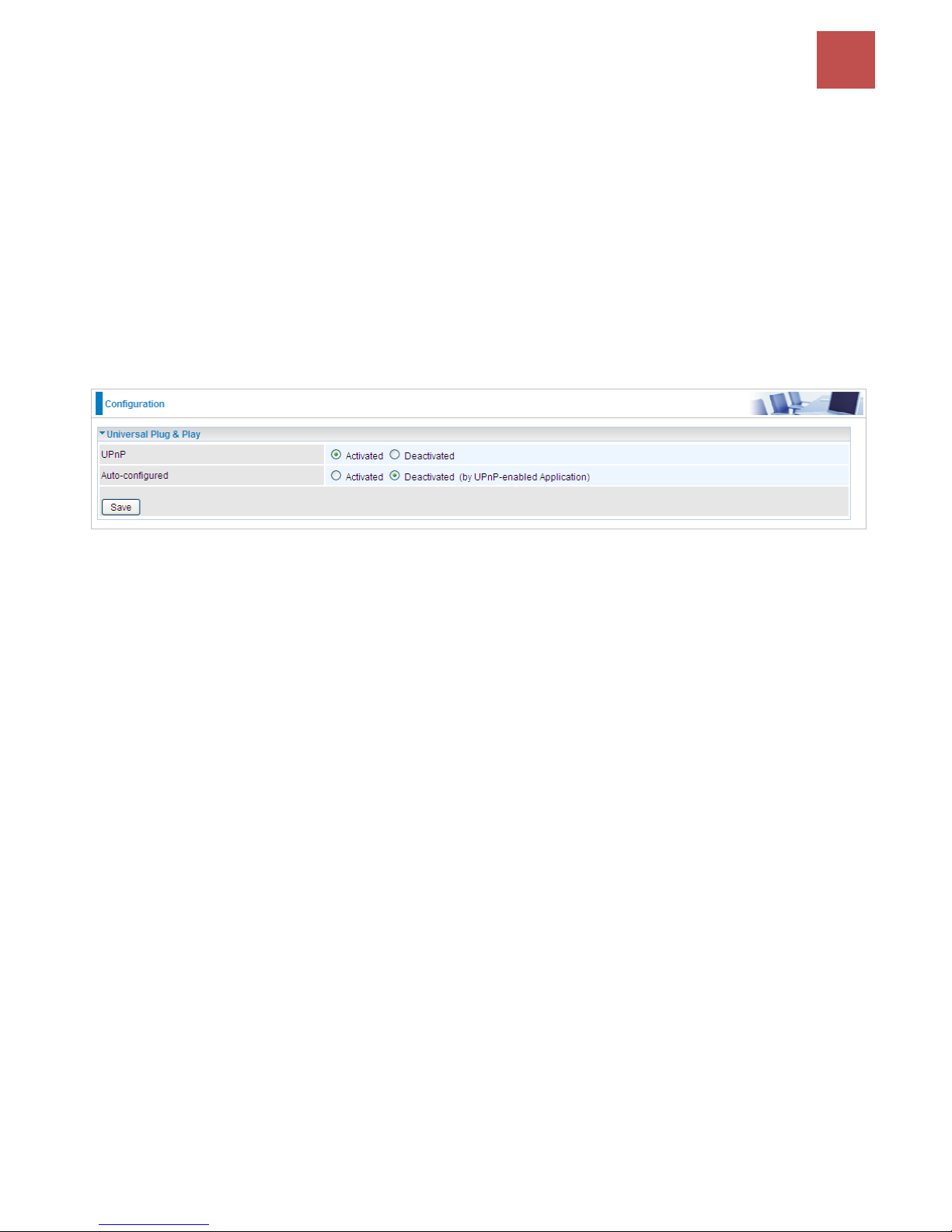
Device Configuration /
Access Management
96
BEC 9800VN User Manual
Universal Plug & Play
UPnP offers peer-to-peer network connectivity for PCs and other network devices, along with control
and data transfer between devices. UPnP offers many advantages for users running NAT routers
through UPnP NAT Traversal, and on supported systems makes tasks such as port forwarding much
easier by letting the application control the required settings, removing the need for the user to control
advanced configuration of their device.
Both the user’s Operating System and the relevant application must support UPnP in addition to the
router. Windows XP and Windows ME natively support UPnP (when the component is installed), and
Windows 98 users may install the Internet Connection Sharing client from Windows XP in order to
support UPnP. Windows 2000 does not support UPnP.
UPnP: Select this checkbox to activate UPnP. Be aware that anyone could use a UPnP application to
open the web configuration’s login screen without entering the BEC 9800VN' IP address
Auto-configured: Select this check box to allow UPnP-enabled applications to automatically
configure the BEC 9800VN so that they can communicate through the BEC 9800VN, for example by
using NAT traversal, UPnP applications automatically reserve a NAT forwarding port in order to
communicate with another UPnP enabled device; this eliminates the need to manually configure port
forwarding for the UPnP enabled application.
 Loading...