

Page 1
User Manual
BEC 6500 Series
4G/LTE Multi-Service
11ac Broadband Router
Last revised: April. 2019
Version release: v1.1
Page 2

Copyright Notice
Copyright@ 2019 BEC Technologies Inc. All rights reserved.
BEC Technologies reserves the right to change and make improvement to this manual at any time
without prior notice.
No part of this document may be reproduced, copied, transmitted in any form or by any means without
prior written permission from BEC Technologies, Inc.
Support Contact Information
Contact Support: http://bectechnologies.net/support/.
Telephone: +1 972 422 0877
Last revised: April. 2019
Version release: v1.1
Page 3

TABLE OF CONTENTS
COPYRIGHT NOTICE ....................................... 1
SUPPORT CONTACT INFORMATION .............. 1
CHAPTER 1: INTRODUCTION ......................... 1
INTRODUCTION TO YOUR ROUTER .............................................................. 1
FEATURES & SPECIFICATIONS .................................................................... 3
HARDWARE SPECIFICATIONS ..................................................................... 6
APPLICATION DIAGRAMS ......................................................................... 7
CHAPTER 2: PRODUCT OVERVIEW ............... 9
IMPORTANT NOTE FOR USING THIS ROUTER ................................................. 9
WHAT’S IN THE BOX ............................................................................... 9
DEVICE DESCRIPTION ............................................................................ 10
Front Panel LEDs (6500AEL & 6500AT) ............................................................ 10
Front Panel LEDs (6500VAL & 6500X) .............................................................. 11
Rear Panel Connectors (6500AEL & 6500AT) ................................................... 12
Rear Panel Connectors (6500VAL & 6500X) ..................................................... 13
HARDWARE CONNECTION ...................................................................... 14
SYSTEM RECOVERY PROCEDURES ............................................................. 16
CABLING ............................................................................................ 17
CHAPTER 3: BASIC INSTALLATION ............. 18
NETWORK CONFIGURATION – IPV4 .......................................................... 19
Configuring PC in Windows 10 (IPv4) .............................................................. 19
Configuring PC in Windows 7/8 (IPv4) .............................................................. 21
Configuring PC in Windows Vista (IPv4) .......................................................... 23
NETWORK CONFIGURATION – IPV6 .......................................................... 25
Configuring PC in Windows 10 (IPv6) .............................................................. 25
Configuring PC in Windows 7/8 (IPv6) .............................................................. 27
Configuring PC in Windows Vista (IPv6) .......................................................... 29
Page 4

DEFAULT SETTINGS ............................................................................... 31
INFORMATION FROM YOUR ISP ............................................................... 32
CHAPTER 4: DEVICE CONFIGURATION....... 33
LOGIN TO YOUR DEVICE ......................................................................... 33
STATUS .............................................................................................. 35
Device Info ...................................................................................................... 35
System Status .................................................................................................. 37
System Log ...................................................................................................... 37
4G/LTE Status ................................................................................................. 38
Wireless Status ................................................................................................ 40
Hotspot Status ................................................................................................. 41
Statistics .......................................................................................................... 42
DHCP Table ...................................................................................................... 45
IPSec Status ..................................................................................................... 45
PPTP Status...................................................................................................... 46
L2TP Status ...................................................................................................... 47
GRE Status ....................................................................................................... 47
VoIP Status ...................................................................................................... 48
Disk Status ....................................................................................................... 49
ARP Table ........................................................................................................ 49
VRRP Status ..................................................................................................... 49
QUICK START ...................................................................................... 50
DEVICE CONFIGURATION ........................................................................ 53
Interface Setup ................................................................................................ 53
Internet ......................................................................................................................... 53
LAN ............................................................................................................................... 61
Wireless 2.4GHz & 5GHz ............................................................................................... 65
Wireless MAC Filter ...................................................................................................... 76
Loopback ...................................................................................................................... 77
Dual WAN ........................................................................................................ 78
General Setting ............................................................................................................. 78
Outbound Load Balance ............................................................................................... 82
Protocol Binding ........................................................................................................... 83
Hotspot ........................................................................................................... 85
General Setting ............................................................................................................. 85
Built-in User Account .................................................................................................... 88
Page 5

Authorized of Client ...................................................................................................... 89
Walled Garden .............................................................................................................. 90
Advertisement .............................................................................................................. 91
Hotspot Status Log ....................................................................................................... 92
Customization ............................................................................................................... 93
Advanced Setup ............................................................................................... 95
Firewall ......................................................................................................................... 95
Routing ......................................................................................................................... 96
Dynamic Routing .......................................................................................................... 97
NAT ............................................................................................................................... 99
VRRP ........................................................................................................................... 104
Static DNS ................................................................................................................... 105
QoS ............................................................................................................................. 106
Time Schedule ............................................................................................................ 108
Mail Alert ................................................................................................................... 109
VPN ............................................................................................................... 110
IPSec ........................................................................................................................... 110
PPTP Server ................................................................................................................ 120
PPTP Client ................................................................................................................. 122
L2TP ............................................................................................................................ 128
GRE Tunnel ................................................................................................................. 135
VoIP ............................................................................................................... 140
Basic ........................................................................................................................... 140
Media ......................................................................................................................... 142
Advanced .................................................................................................................... 143
Speed Dial ................................................................................................................... 144
Dial Plan ..................................................................................................................... 146
Call Features ............................................................................................................... 150
NAT Traversal for VoIP................................................................................................. 153
Access Management ..................................................................................... 155
Device Management ................................................................................................... 155
SNMP.......................................................................................................................... 156
Syslog ......................................................................................................................... 158
Universal Plug & Play .................................................................................................. 159
Dynamic DNS .............................................................................................................. 160
Access Control ............................................................................................................. 162
Packet Filter ................................................................................................................ 164
CWMP (TR-069) .......................................................................................................... 168
Parental Control .......................................................................................................... 170
SAMBA & FTP Server ................................................................................................... 171
BECentral Management .............................................................................................. 174
Maintenance ................................................................................................. 175
User Management ...................................................................................................... 175
Page 6

Time Zone ................................................................................................................... 177
Firmware & Configuration .......................................................................................... 178
System Restart ............................................................................................................ 179
Auto Reboot ................................................................................................................ 180
Diagnostics Tool .......................................................................................................... 181
CHAPTER 5: TROUBLESHOOTING ............ 183
Problems with the Router ............................................................................. 183
Problem with LAN Interface .......................................................................... 183
Recovery Procedures ..................................................................................... 184
APPENDIX: PRODUCT SUPPORT & CONTACT
....................................................................... 185
FCC STATEMENT ................................................................................ 186
Page 7

Introduction
1
CHAPTER 1: INTRODUCTION
Introduction to your Router
Congratulations on your purchase of the BEC 6500 series router (4G/LTE Enterprise Multi-Service
Router). The BEC 6500 series is a 4G/LTE Multi-Service with 11ac High Power Router – featuring a
Dual-WAN interface (4G/LTE and GigaConnect® Ethernet WAN), 4-port Gigabit Ethernet Switch,
USB 2.0, 802.11ac dual-band Wi-Fi access point, Hotspot, Voice ports, dynamic routing and a robust
Firewall security. The BEC 6500 series offers mobile 4G/LTE service with multiple speed rate from
100Mbps up to 600Mbps in downlink and 50Mbps to 150Mbps in uplink and also support a variety of
fixed broadband connections types, including ADSL2+ / VDSL2 / FTTH / Cable modems, with data
rates reaching up to 1Gbps.
A well-designed GUI offers administrators / home owners a simple and easy way to secure and mange
networks through many advanced features. Equipped with11ac and dual bands technologies with
high transmit RF power on both frequency bands, the BEC 6500 series is capable to provide
simultaneous dual band connections with dedicated Wi-Fi streams for specific network applications
and extend Wi-Fi signal providing outstanding range and coverage throughout the home or office.
4G/LTE and Fixed Broadband Service Ready
The BEC 6500 series provides 4G/LTE mobile and gigabit wired Ethernet WAN interfaces and is
featuring an auto-failover to ensure maximum Internet accessibility with minimum service interruption.
This seamless automatic failover with traffic prioritization in the event of an Internet connectivity failure
of the primary WAN interface, traffic is automatically redirected to the secondary WAN interface within
seconds. This functionality operates regardless of whether the primary connection is LTE or a wired
connection.
New Experience with Wi-Fi Speed and Coverage
BEC 6500 support a link rate up to 300Mbps in 2.4GHz frequency range & 866Mbps in 5GHz range
and is also backward compatible with existing 802.11 a / b / g / n wireless equipment in the network.
The Wireless Protected Access (WPA-PSK/WPA2-PSK) and Wireless Encryption Protocol (WEP)
features enhance the level of transmission security and access control over Wireless LAN. The BEC
6500 also supports the Wi-Fi Protected Setup (WPS) standard for easy and secure establishment of a
wireless home network. If the user’s network requires wider coverage, the built-in Wireless Distribution
System (WDS) repeater function expands the wireless network without needing any external wires or
cables.
Wi-Fi Hotspot with Captive Portal
BEC 6500 offer Wi-Fi hotspot to share the Internet connection via mobile (4G/LTE) or a wired
connection, an existing FTTH, cable, DSL network or modem, with any wireless-enabled devices
which is completed separate from the private Wi-Fi network. The captive portal enables highly secure
connectivity with multiple authentication options and extensive controls for access and bandwidth
management. Customization options allow for operator logos, branding or advertisement placement.
BEC 6500 Series User Manual
Page 8

Introduction
2
Cost Saving
Making VoIP calls is extremely simple; just connect the router with your existing analog telephones.
BEC 6500 series complies with the most popularly adopted VoIP standard and SIP protocol to ensure
interoperability with SIP devices and major VoIP Gateways. This router also supports a wider range of
telephony features, such as Call Waiting, Conference, Speed Dial, Return Call, Redial, etc.
4G/LTE Management Center
The Mobile Management Center visually displays its current 4G/LTE signal status also calculates the
total amount of hours or data traffic used per month, allowing you to manage your 4G/LTE monthly
subscriptions.
IPv6 Supported
Internet Protocol version 6 (IPv6) is a version of the Internet Protocol that is designed to succeed IPv4.
IPv6 has a vastly larger address space than IPv4. The router is already supporting IPv6, you can use it
in IPv6 environment no need to change device. The dual-stack protocol implementation in an
operating system is a fundamental IPv4-to-IPv6 transition technology. It implements IPv4 and IPv6
protocol stacks either independently or in a hybrid form. The hybrid form is commonly implemented in
modern operating systems supporting IPv6.
Quick Start Wizard
Support a WEB GUI page to install this device quickly. With this wizard, simple steps will get you
connected to the Internet immediately.
Firmware Upgradeable
Device can be upgraded to the latest firmware through the WEB based GUI.
BEC 6500 Series User Manual
Page 9

Introduction
Features & Specifications
3
Features & Specifications
• 4G/LTE for high speed mobile broadband connectivity
• Gigabit Ethernet WAN (GbE WAN) for Cable/Fiber/xDSL high WAN throughput
•
Gigabit Ethernet LAN
• IPv6 ready (IPv4/IPv6 dual stack)
• Multiple wireless SSIDs with wireless guest access and client isolation
• IEEE
Wi-Fi Protected Access (WPA-PSK/ WPA2-PSK) and Wired Equivalent Privacy (WEP)
•
SOHO Firewall Security with DoS Preventing and Packet Filtering
•
Quality of Service Control for traffic prioritization management
•
Universal Plug and Play (UPnP) Compliance
•
• Voice over IP compliant with SIP standard (BEC 6500VAL)
• Two FXS ports for connecting to regular analog telephones (BEC 6500VAL)
• Call Waiting, Conference Call (BEC 6500VAL)
• Speed Dial, Return Call, Redial (BEC 6500VAL)
• Don’t Disturb (BEC 6500VAL)
• Ease of Use with Quick Installation Wizard
802.11 a/ac/b/g/n compliant Wireless Access Point with Wi-Fi Protected Setup (WPS)
• One
• Ideal for SOHO, office, and home users
Network Protocols and Features
•
•
•
•
•
•
•
•
•
USB port for NAS (FTP/ SAMBA server)
IPv4, IPv6 or IPv4 / IPv6 Dual Stack
NAT, static (v4/v6) routing and RIP-1 / 2
DHCPv4 / v6
Universal Plug and Play (UPnP) Compliant
Dynamic Domain Name System (DDNS)
Virtual Server and DMZ
SNTP, DNS proxy
IGMP snooping and IGMP proxy
MLD snooping and MLD proxy
BEC 6500 Series User Manual
Page 10

Introduction
Features & Specifications
4
Firewall
Built-in NAT Firewall
•
Stateful Packet Inspection (SPI)
•
• DoS attack prevention including Land Attack, Ping of Death, etc.
• Access control
• IP&MAC filter, URL Content Filter
• Password protection for system management
• VPN pass-through
Quality of Service Control
Traffic prioritization management based-on Protocol, Port Number and IP Address (IPv4/ IPv6)
•
Wireless LAN
Compliant with IEEE 802.11 a/b/g/n/ac standards
•
2.4GHz & 5GHz frequency range
•
20/40-MHz channel bandwidth
•
Up to 300Mbps (2.4GHz) & 866Mbps (5GHz) wireless data phy rate
•
64/128 bits WEP supported for encryption
•
Wireless security with WPA-PSK, WPA2-PSK, Mixed WPA/WAP2-PSK, (TKIP/AES),
•
802.1x/Radius
AP, Client Bridge and WDS Operational Modes
•
Multiple SSID (4 SSIDs), BSSID
•
Wireless MAC filtering
•
Wireless Client Isolation
•
Wi-Fi Hotspot with Captive Portal
•
• Dynamic, Wi-Fi client rate-limiting
USB Application Server
Storage/NAS: SAMBA Server, FTP Server
•
• 4G/LTE Mobile Internet Connection
VoIP (6500VAL & 6500X Only)
Compliant with SIP standard (RFC3261)
•
Codec: G.729, G.726, G.711 A-Law, G.711 u-Law
•
DTMF Method: Inband, RFC 2833, SIP Info
•
BEC 6500 Series User Manual
Page 11

Introduction
Features & Specifications
5
Caller ID Generation: DTMF, FSK
•
Silence Suppression (VAD), Echo Cancellation
•
Call Waiting, Conference Call
•
Speed Dial, Return Call, Redial
•
Don't Disturb
•
FAX Relay: T.38
•
Call Detailed Records (CDR)
•
Management
• Quick Installation wizard
Web-based GUI for remote and local management (IPv4/IPv6)
•
Firmware upgrades and configuration data upload and download via web-based GUI
•
Supports DHCP server / client / relay
•
• Supports
TR-069 supports remote management
•
SNMP v1, v2, v3, MIB-I and MIB-II
• BECentral® Remote Management
BEC 6500 Series User Manual
Page 12

Introduction
Hardware Specifications
6
Hardware Specifications
Physical interface
4G LTE antenna: 2 external female SMA connectors (up to 4 connectors – 6500 R18/R20)
•
5G Wi-Fi antenna: 2 external female RP-SMA connectors
•
SIM card slot: Mini SIM card (2FF) slot for mobile broadband connectivity
•
VoIP phone port: 2 RJ-11 FXS phone ports to connect with 2 regular analog phones. (6500VAL &
•
6500VL only)
• Wireless on/off and
Factory default reset button
•
Ethernet: 4-port 10 / 100 / 1000Mbps auto-crossover (MDI / MDI-X) Switch
•
- 1 x Versatile Port : LAN 4 / WAN
USB: USB 2.0 port for storage service
•
Power DC Jack
•
• Power Button On/Off
LED Indicators
•
Physical Specifications
• Dimensions (W*H*D): 9.04" x 6.10" x 1.69"(229.5mm x 155mm x 43mm)
Power Requirement
• Input: 15V DC, 1.6A
WPS push button
BEC 6500 Series User Manual
Page 13

Introduction
Application Diagrams
7
Application Diagrams
BEC 6500 series (4G/LTE Multi-Service 11ac Broadband Router) is an all-in-one router,
supporting multiple WAN connection options (4/LTE, Fixed Broadband and Auto WAN Failover) to
connect to the Internet.
4G/LTE Router Mode
With an embedded 4G/LTE module, the router can be used to connect to high speed mobile fixed
wireless connection.
FTTH / Broadband Router Mode
This router also has a Gigabits Ethernet WAN port (EWAN) to connect with your Fiber / Cable/ xDSL
modem.
BEC 6500 Series User Manual
Page 14

Introduction
Application Diagrams
8
Automatic WAN Failover
The automatic failover ensures uninterrupted operation and 24/7 Internet availability. When Primary
WAN connection fails, the Secondary connection will back up the Internet connection seamlessly.
BEC 6500 Series User Manual
Page 15
Product Overview
9
✓ Place the router on a stable surface.
✓ Only use the power adapter that comes with the package. Using
a different voltage rating power adaptor may damage the router.
Attention
✓ Do not use the router in high humidity or high temperature.
✓ Do not use the same power source for the BEC 6500 on other
equipment.
✓ Do not open or repair the case yourself. If the device becomes
too hot, turn off the power immediately and have it repaired at
a qualified service center.
✓ Avoid using this product and all accessories outdoors.
Warning
CHAPTER 2: PRODUCT OVERVIEW
Important Note for Using This Router
What’s in the Box
✓ BEC 6500 series 4G/LTE 11ac Broadband Router x 1
✓ This Quick Start Guide x 1
✓ Wi-Fi Antenna x 2
✓ RJ-45 Ethernet Cable x 1
✓ DC Power Adapter x 1
✓ 4G/LTE Antenna x 2 ( BEC 6500 R18/R21: 4 LTE antennas)
BEC 6500 Series User Manual
Page 16
Product Overview
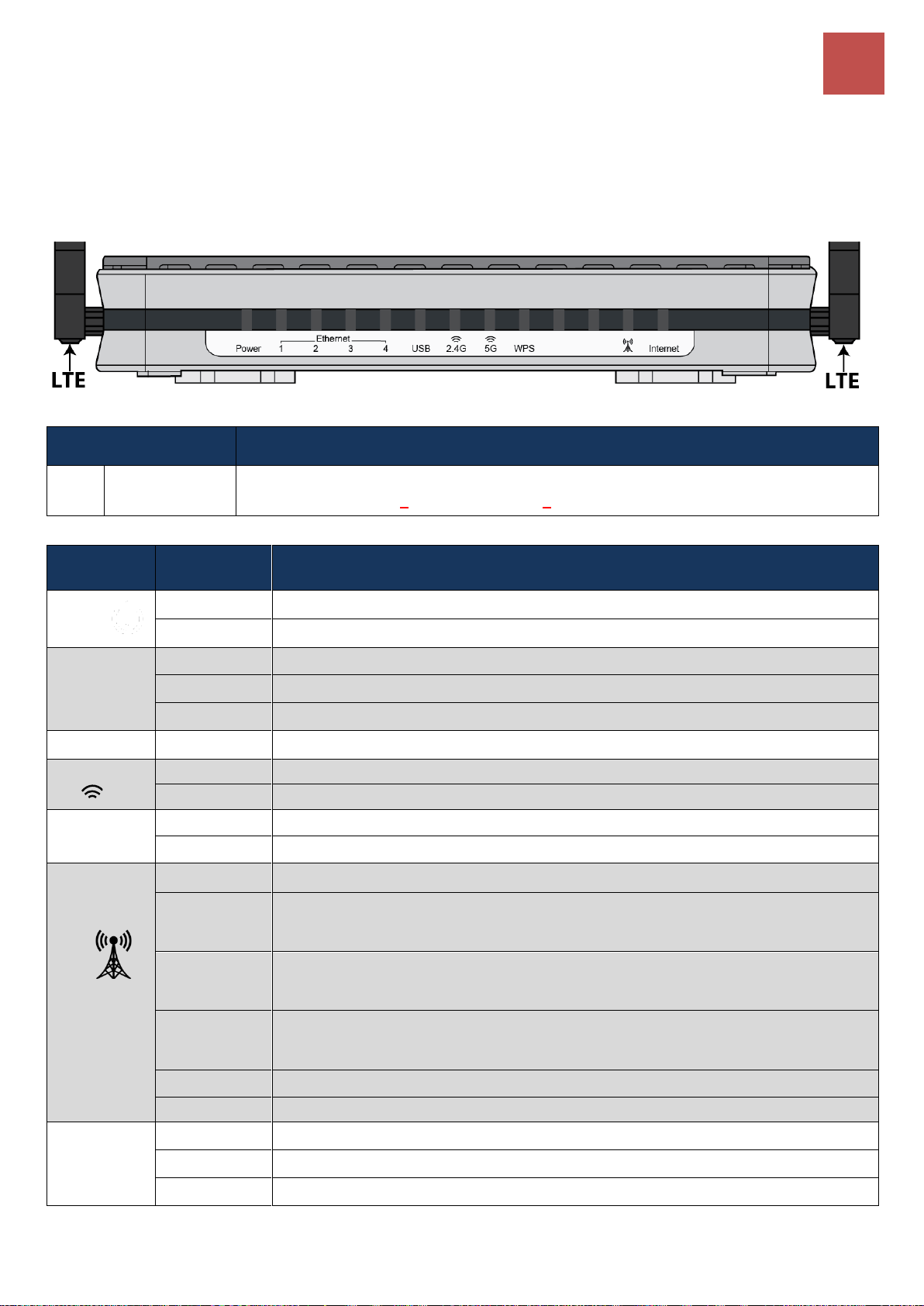
Device Description / Front Panel LEDs (6500AEL & 6500AT)
10
PORT
MEANING
1
LTE Antenna
Connectors
Screw the supplied mobile LTE antennas onto the antenna connectors on both sides.
(6500 R18 / R21 uses 4 LTE antennas and 2 Wi-Fi antennas)
LED
STATUS
DESCRIPTION
Power
Green
System is up and ready
Red
Boot failure
Ethernet
Port
LAN 1 - 4
Green
Transmission speed is at Gigabit speed (1000Mbps)
Orange
Transmission speed is at 10/100Mbps
Blinking
Data being transmitted/received
USB
Green
Connecting to a USB dongle or a hard drive.
Wi-Fi 2.4G /
5G
Green
Wireless connection to 2.4G or 5G network is established
Blinking
Data being transmitted / received
WPS
Green
Wireless device(s) being connected successfully via WPS mode
Blinking
WPS is enabled and trying to establish a WPS connection
LTE
(Received
Signal
Strength
Indicator)
Green
RSSI greater than -69 dBm. Excellent signal condition
Green
Flashing
Quickly
RSSI from -81 to -69 dBm. Good signal condition
Orange
Flashing
Quickly
RSSI from -99 to -81 dBm. Fair signal condition.
Orange
Flashing
Slowly
RSSI less than -99 dBm. Poor signal condition.
Orange
No signal and the 4G_LTE module is in service
Off
No LTE module or LTE module fails
Internet
Green
WAN IP is received, and traffic is passing thru the device.
Red
Cannot get a WAN/public IP address
Off
The device is either in bridged mode or WAN connection not ready.
Device Description
Front Panel LEDs (BEC 6500AEL & BEC 6500AT)
BEC 6500 Series User Manual
Page 17
Product Overview
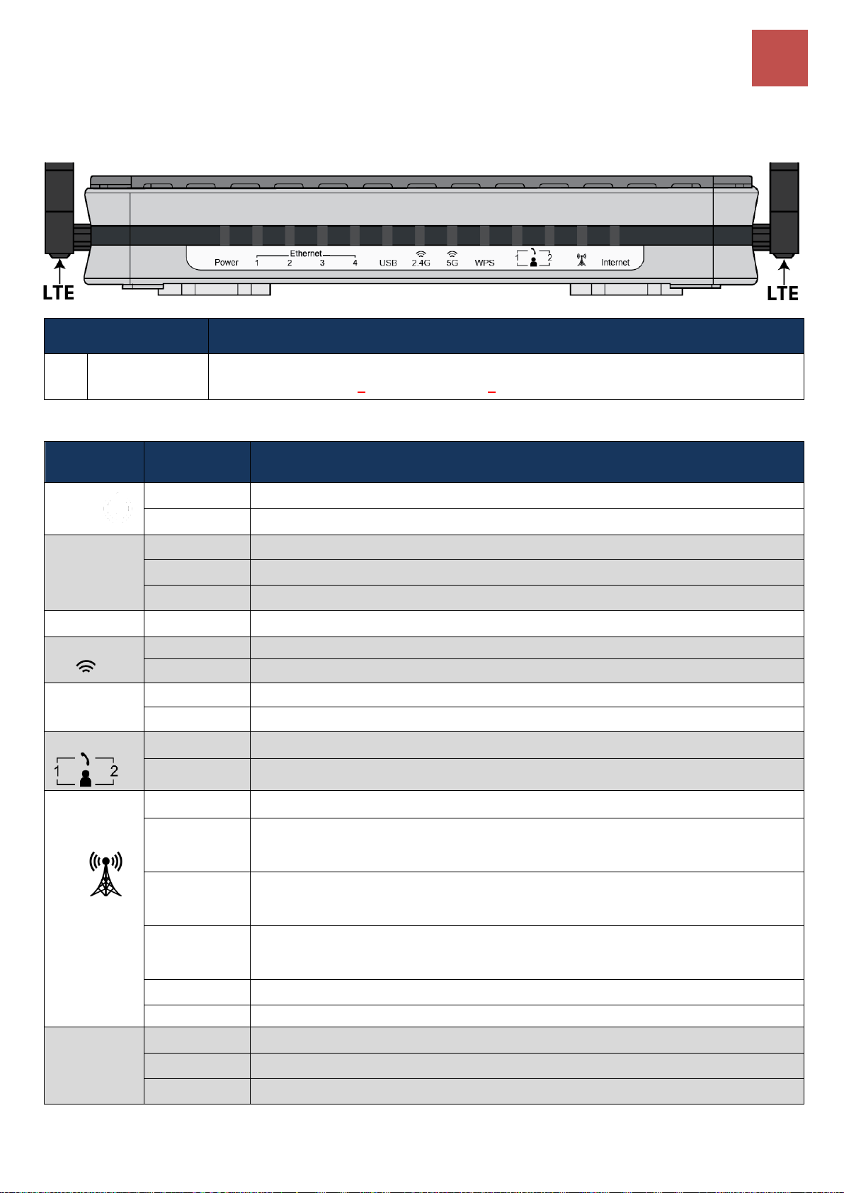
Device Description / Front Panel LEDs (6500VAL & 6500X)
11
PORT
MEANING
1
LTE Antenna
Connectors
Screw the supplied mobile LTE antennas onto the antenna connectors on both sides.
(6500 R18 / R21 uses 4 LTE antennas and 2 Wi-Fi antennas)
LED
STATUS
DESCRIPTION
Power
Green
System is up and ready
Red
Boot failure
Ethernet
Port
LAN 1 - 4
Green
Transmission speed is at Gigabit speed (1000Mbps)
Orange
Transmission speed is at 10/100Mbps
Blinking
Data being transmitted/received
USB
Green
Connecting to a USB dongle or a hard drive.
Wi-Fi 2.4G /
5G
Green
Wireless connection to 2.4G or 5G network is established
Blinking
Data being transmitted / received
WPS
Green
Wireless device(s) being connected successfully via WPS mode
Blinking
WPS is enabled and trying to establish a WPS connection
Phone
Green
Successfully registered and ready to be used.
Orange
Phone is off-hook, in-use.
LTE
(Received
Signal
Strength
Indicator)
Green
RSSI greater than -69 dBm. Excellent signal condition
Green
Flashing
Quickly
RSSI from -81 to -69 dBm. Good signal condition
Orange
Flashing
Quickly
RSSI from -99 to -81 dBm. Fair signal condition.
Orange
Flashing
Slowly
RSSI less than -99 dBm. Poor signal condition.
Orange
No signal and the 4G_LTE module is in service
Off
No LTE module or LTE module fails
Internet
Green
WAN IP is received, and traffic is passing thru the device.
Red
Cannot get a WAN/public IP address
Off
The device is either in bridged mode or WAN connection not ready.
Front Panel LEDs (BEC 6500VAL & BEC 6500X)
BEC 6500 Series User Manual
Page 18
Product Overview
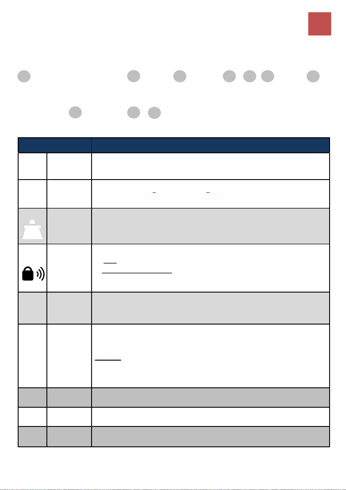
Device Description / Rear Panel Connectors (6500AEL & 6500AT)
12
PORT
MEANING
1
Wi-Fi
Antenna
Connectors
Screw the supplied Wi-Fi antennas onto the antenna connectors on both sides.
1
LTE Antenna
Connectors
(6500 R18 / R21 uses 4 LTE antennas and 2 Wi-Fi antennas)
Screw the supplied mobile LTE antennas onto the antenna connectors on both sides.
2
SIM Card Slot
Insert the mini SIM card (2FF) with the gold contact facing down.
Push the mini SIM card (2FF) inwards to eject it
3
WPS &
Wireless
On/Off
By controlling the pressing time, users can achieve two different effects:
(1) WPS*: Press &hold the button for less than 6 seconds to trigger WPS function.
(2) Wireless ON/OFF button: Press & hold the button for more than 6 seconds to enable
or disable the wireless.
* Refer to the WPS section in the User Manual for more details.
4
Reset
After the device is powered on, press it 6 seconds or above: to restore to factory default
settings (this is used when you cannot login to the router, e.g. forgot your password)
5
Gigabit
LAN Ethernet
(1 - 4)
Connect a UTP Ethernet cable (Cat-5 or Cat-5e) to one of the four LAN ports when
connecting to a PC or an office/home network of 10Mbps /100Mbps /1000Mbps
* EWAN/4
Connect to Fiber/ Cable/ xDSL Modem with a RJ-45 cable, for broadband connectivity.
Note: LAN 4 automatically becomes an EWAN port when EWAN internet interface is being
selected in the GUI
6
USB
The USB can either setup for 4G/LTE internet access or storage/file sharing.
7
DC Power
Jack
Connect the supplied Power Adapter to this jack.
8
Power
ON/OFF
Power ON/OFF switch
1 2 7
1 8 3 5 6 4 *
Rear Panel Connectors (BEC 6500AEL & BEC 6500AT)
BEC 6500 Series User Manual
Page 19
Product Overview
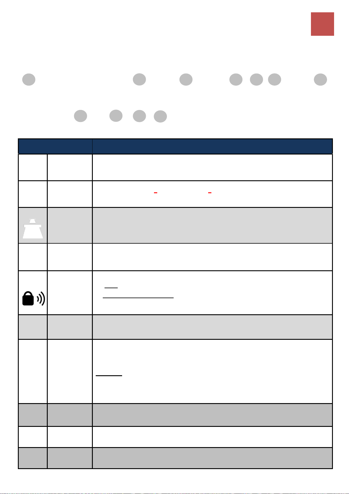
Device Description / Rear Panel Connectors (6500VAL & 6500X)
13
PORT
MEANING
1
Wi-Fi
Antenna
Connectors
Screw the supplied Wi-Fi antennas onto the antenna connectors on both sides.
1
LTE Antenna
Connectors
(6500 R18 / R21 uses 4 LTE antennas and 2 Wi-Fi antennas)
Screw the supplied mobile LTE antennas onto the antenna connectors on both sides.
2
SIM Card Slot
Insert the mini SIM card (2FF) with the gold contact facing down.
Push the mini SIM card (2FF) inwards to eject it
3
Phone
(1X-2X)
Connect your analog phone to this port with a RJ-11 cable.
4
WPS &
Wireless
On/Off
By controlling the pressing time, users can achieve two different effects:
(1) WPS*: Press &hold the button for less than 6 seconds to trigger WPS function.
(2) Wireless ON/OFF button: Press & hold the button for more than 6 seconds to enable
or disable the wireless.
* Refer to the WPS section in the User Manual for more details.
5
Reset
After the device is powered on, press it 6 seconds or above: to restore to factory default
settings (this is used when you cannot login to the router, e.g. forgot your password)
6
Gigabit
LAN Ethernet
(1 - 4)
Connect a UTP Ethernet cable (Cat-5 or Cat-5e) to one of the four LAN ports when
connecting to a PC or an office/home network of 10Mbps /100Mbps /1000Mbps
* EWAN/4
Connect to Fiber/ Cable/ xDSL Modem with a RJ-45 cable, for broadband connectivity.
Note: LAN 4 automatically becomes an EWAN port when EWAN internet interface is being
selected in the GUI
7
USB
The USB can either setup for 4G/LTE internet access or storage/file sharing.
8
DC Power
Jack
Connect the supplied Power Adapter to this jack.
9
Power
ON/OFF
Power ON/OFF switch
1
2
8 1 9 5 6
7 4 *
3
Rear Panel Connectors (BEC 6500VAL & BEC 6500X)
BEC 6500 Series User Manual
Page 20

Product Overview
Hardware Connection
14
Hardware Connection
Back Panel Ports & Connectors
Wi-Fi & LTE Antenna Connectors (Standard Version)
BEC 6500 Series User Manual
Page 21

Product Overview
Hardware Connection
15
Wi-Fi & LTE Antenna Connectors (BEC 6500 R18 / R21 Only)
BEC 6500 Series User Manual
Page 22

Product Overview
System Recovery Procedures
16
System Recovery Procedures
The purpose is to allow users to restore the BEC 6500 to its initial stage when the device is outage,
upgraded to a wrong / broken firmware, cannot access to the GUI with wrong username and/or
password, etc.
Step 1 – Configure your PC Network IP Address
Before performing the system recovery, assign this IP address and Netmask to your PC,
192.168.1.100 and 255.255.255.0 respectively.
Step 2 – Reset your BEC 6500 Device
2.1 Power off your BEC 6500
2.2 Power on the BEC 6500 while pushing the RESET button with a small pointed object (such as
paper clip, needle, toothpick, and etc.).
2.3 When the POWER LED turns RED, keep holding and pushing the RESET button for more 6
seconds then release it. The INTERNET LED will flash in GREEN afterward.
Step 3 – Restore your 6500 Device
With INTERNET light flashes green, BEC 6500 is in recovery mode and ready for a new Firmware.
3.1 Open a web browser and type the IP address, 192.168.1.1, to access to the recovery page.
NOTE: In the recovery mode, 6500 will not respond to any PING or other requests.
3.2 Browse to the new Firmware image file then click Upload to start the upgrade process.
3.3 INTERNET LED turns red means the Firmware upgrade is in process.
DO NOT power off or reboot the device, it would permanently damage your 6500.
3.4 INTERNET LED turns green after the Firmware upgrade completed
3.5 Power cycle on & off to regain access to your BEC 6500.
BEC 6500 Series User Manual
Page 23

Product Overview
Cabling
17
Cabling
One of the most common causes of problems is bad cabling. Make sure that all connected devices are
turned on. On the front panel of the product is a bank of LEDs. Verify that the LAN Link and LEDs are
lit. If they are not, verify that you are using the proper cables.
Make sure that all other devices (e.g. telephones, fax machines, analogue modems) connected to the
same telephone line as your BEC router have a line filter connected between them and the wall socket
(unless you are using a Central Splitter or Central Filter installed by a qualified and licensed electrician),
and that all line filters are correctly installed in a right way. If the line filter is not correctly installed and
connected, it may cause problems to your connection or may result in frequent disconnections.
BEC 6500 Series User Manual
Page 24

Basic Installation
18
Any TCP/IP capable workstation can be used to communicate with or
through the BEC 6500. To configure other types of workstations,
please consult the manufacturer’s documentation.
CHAPTER 3: BASIC INSTALLATION
The router can be configured with your web browser. A web browser is included as a standard
application in the following operating systems: Windows XP / 7 / 8 / Vista, Linux, Mac OS, etc. The
product provides an easy and user-friendly interface for configuration.
PCs must have an Ethernet interface installed properly and be connected to the router either directly or
through an external repeater hub and have TCP/IP installed or configured to obtain an IP address
through a DHCP server or a fixed IP address that must be in the same subnet as the router. The
default IP address of the router is 192.168.1.254 and the subnet mask is 255.255.255.0 (i.e. any
attached PC must be in the same subnet and have an IP address in the range of 192.168.1.1 to
192.168.1.253). The best and easiest way is to configure the PC to get an IP address automatically
from the router using DHCP. If you encounter any problems accessing the router’s web interface it may
also be advisable to uninstall any kind of software firewall on your PCs, as they can cause problems
accessing the 192.168.1.254 IP address of the router. Users should make their own decisions on how
to best protect their network.
Please follow the steps below for your PC’s network environment installation. First of all, please check
your PC’s network components. The TCP/IP protocol stack and Ethernet network adapter must be
installed. If not, please refer to your Windows-related or other operating system manuals.
BEC 6500 Series User Manual
Page 25
Basic Installation
Network Configuration – Windows 10 (IPv4)
19
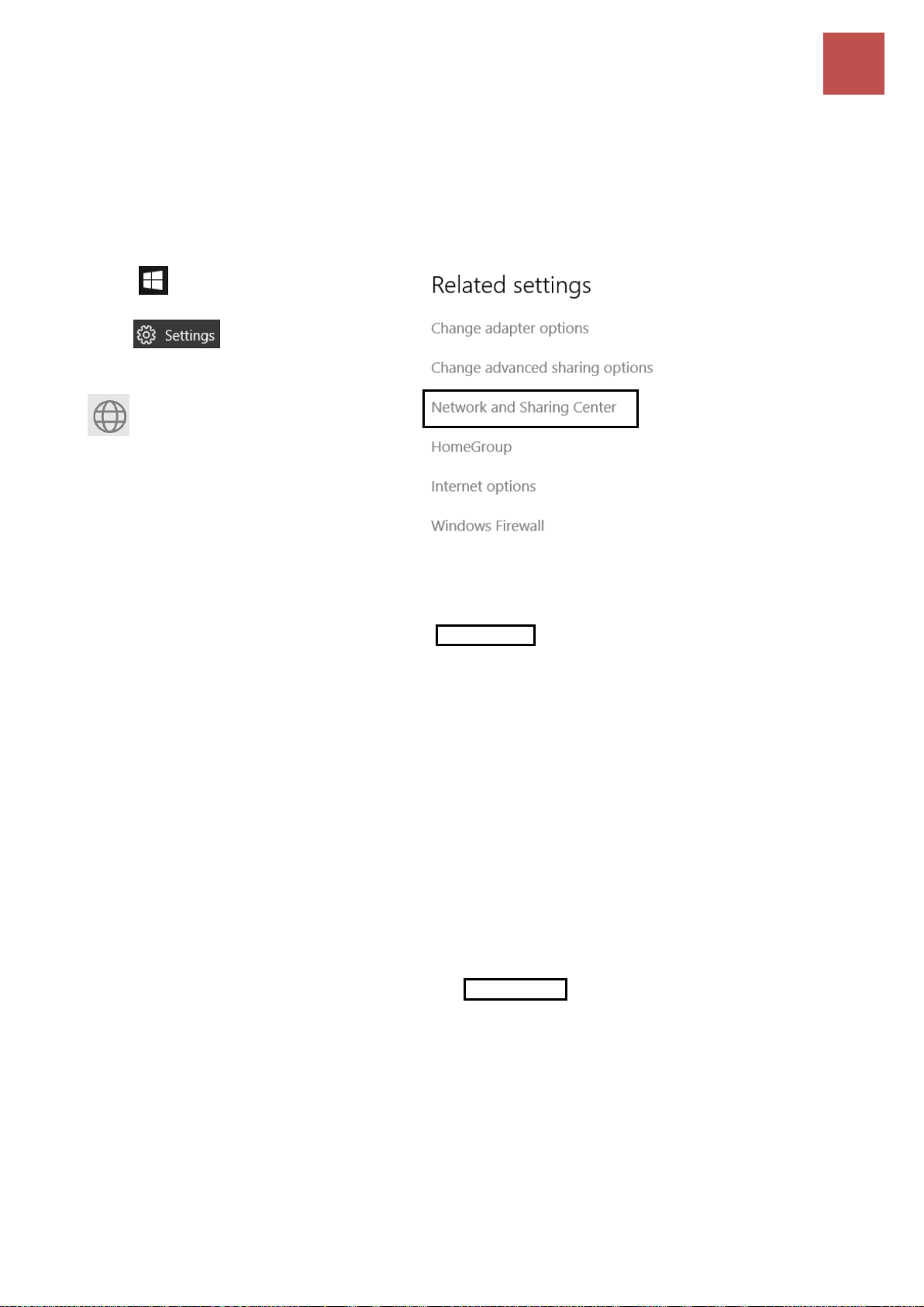
1. Click .
2. Click
3. Then click on Network and Internet.
4. Under Related settings, select
Network and Sharing Center
5. When the Network and Sharing
Center window pops up, select and
click on Change adapter settings on
the left window panel.
6. Select the Local Area Connection,
and right click the icon to select
Properties.
Network Configuration – IPv4
Configuring PC in Windows 10 (IPv4)
BEC 6500 Series User Manual
Page 26
Basic Installation
Network Configuration – Windows 10 (IPv4)
20
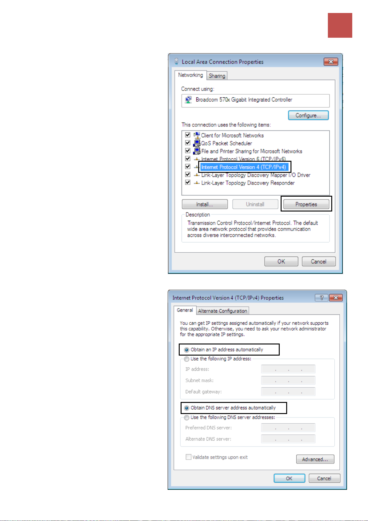
7. Select Internet Protocol Version 4
(TCP/IPv4) then click Properties.
8. In the TCP/IPv4 properties window,
select the Obtain an IP address
automatically and Obtain DNS
Server address automatically radio
buttons. Then click OK to exit the
setting.
9. Click OK again in the Local Area
Connection Properties window to
apply the new configuration.
BEC 6500 Series User Manual
Page 27

Basic Installation
Network Configuration – Windows 7/8 (IPv4)
21
1. Go to Start. Click on Control Panel.
2. Then click on Network and Internet.
3. When the Network and Sharing
Center window pops up, select and
click on Change adapter settings on
the left window panel.
4. Select the Local Area Connection,
and right click the icon to select
Properties.
Configuring PC in Windows 7/8 (IPv4)
BEC 6500 Series User Manual
Page 28
Basic Installation
Network Configuration – Windows 7/8 (IPv4)
22
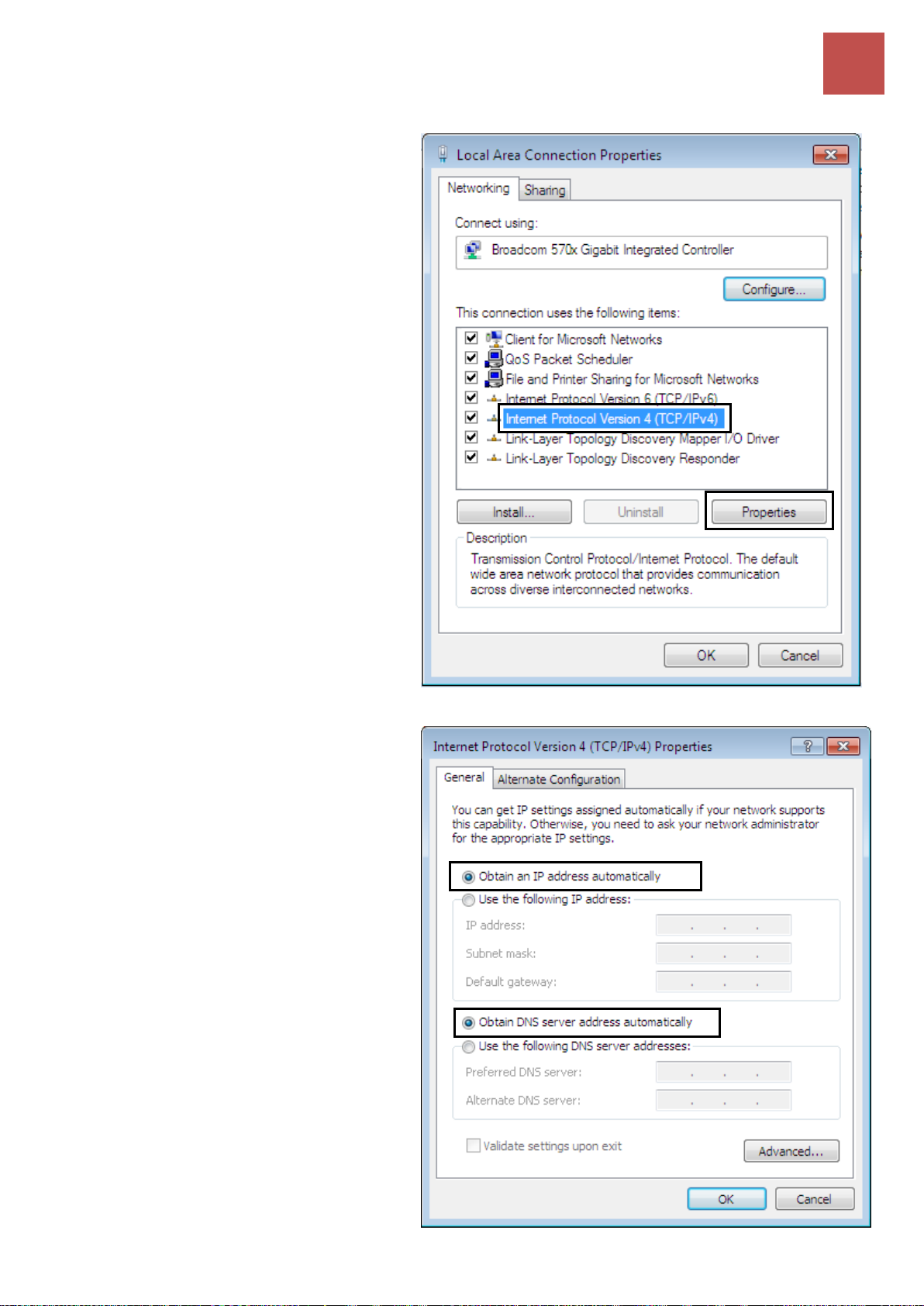
5. Select Internet Protocol Version 4
(TCP/IPv4) then click Properties.
6. In the TCP/IPv4 properties window,
select the Obtain an IP address
automatically and Obtain DNS
Server address automatically radio
buttons. Then click OK to exit the
setting.
7. Click OK again in the Local Area
Connection Properties window to
apply the new configuration.
BEC 6500 Series User Manual
Page 29

Basic Installation
Network Configuration – Windows Vista (IPv4)
23
1. Go to Start. Click on Network.
2. Then click on Network and Sharing
Center at the top bar.
3. When the Network and Sharing
Center window pops up, select and
click on Manage network
connections on the left window
pane.
4. Select the Local Area Connection,
and right click the icon to select
Properties.
Configuring PC in Windows Vista (IPv4)
BEC 6500 Series User Manual
Page 30

Basic Installation
Network Configuration – Windows Vista (IPv4)
24
5. Select Internet Protocol Version 4
(TCP/IPv4) then click Properties.
6. In the TCP/IPv4 properties window,
select the Obtain an IP address
automatically and Obtain DNS Server
address automatically radio buttons.
Then click OK to exit the setting.
7. Click OK again in the Local Area
Connection Properties window to apply
the new configuration.
BEC 6500 Series User Manual
Page 31
Basic Installation
Network Configuration – Windows 10 (IPv6)
25
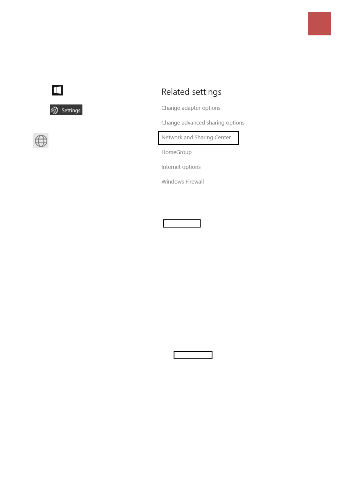
1. Click .
2. Click
3. Then click on Network and Internet.
4. Under Related settings, select
Network and Sharing Center
5. When the Network and Sharing
Center window pops up, select and
click on Change adapter settings on
the left window panel.
6. Select the Local Area Connection,
and right click the icon to select
Properties.
Network Configuration – IPv6
Configuring PC in Windows 10 (IPv6)
BEC 6500 Series User Manual
Page 32
Basic Installation
Network Configuration – Windows 10 (IPv6)
26
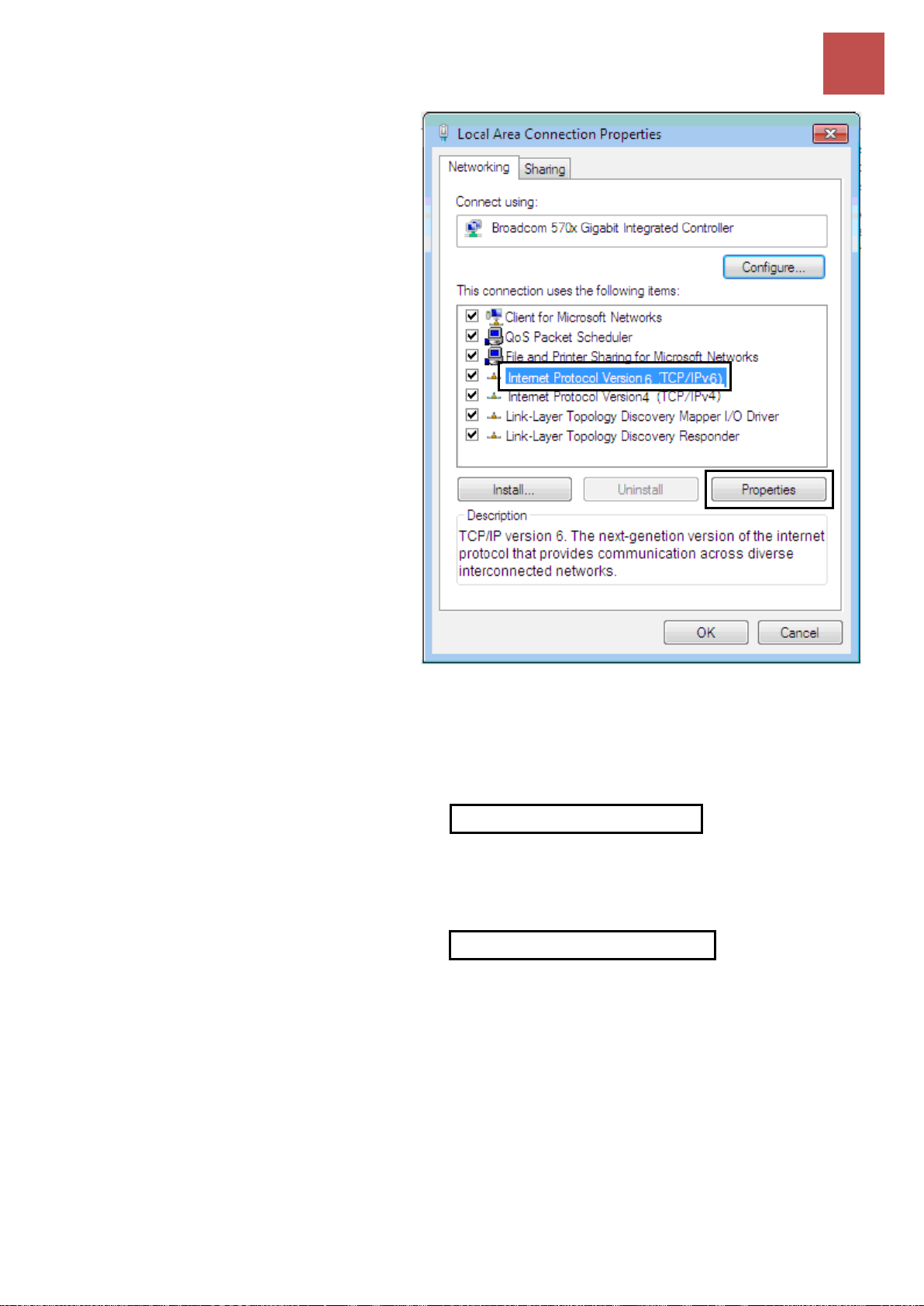
7. Select Internet Protocol Version 6
(TCP/IPv6) then click Properties.
8. In the TCP/IPv6 properties window,
select the Obtain an IPv6 address
automatically and Obtain DNS
Server address automatically radio
buttons. Then click OK to exit the
setting.
9. Click OK again in the Local Area
Connection Properties window to
apply the new configuration.
BEC 6500 Series User Manual
Page 33

Basic Installation
Network Configuration – Windows 7/8 (IPv6)
27
1. Go to Start. Click on Control Panel.
2. Then click on Network and Internet.
3. When the Network and Sharing
Center window pops up, select and
click on Change adapter settings on
the left window panel.
4. Select the Local Area Connection,
and right click the icon to select
Properties.
Configuring PC in Windows 7/8 (IPv6)
BEC 6500 Series User Manual
Page 34
Basic Installation
Network Configuration – Windows 7/8 (IPv6)
28
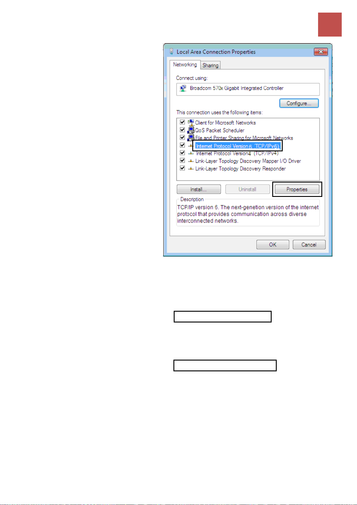
5. Select Internet Protocol Version 6
(TCP/IPv6) then click Properties.
6. In the TCP/IPv6 properties window,
select the Obtain an IPv6 address
automatically and Obtain DNS
Server address automatically radio
buttons. Then click OK to exit the
setting.
7. Click OK again in the Local Area
Connection Properties window to
apply the new configuration.
BEC 6500 Series User Manual
Page 35

Basic Installation
Network Configuration – Windows Vista (IPv6)
29
1. Go to Start. Click on Network.
2. Then click on Network and Sharing
Center at the top bar.
3. When the Network and Sharing
Center window pops up, select and
click on Manage network
connections on the left window
pane.
4. Select the Local Area Connection,
and right click the icon to select
Properties.
Configuring PC in Windows Vista (IPv6)
BEC 6500 Series User Manual
Page 36
Basic Installation
Network Configuration – Windows Vista (IPv6)
30
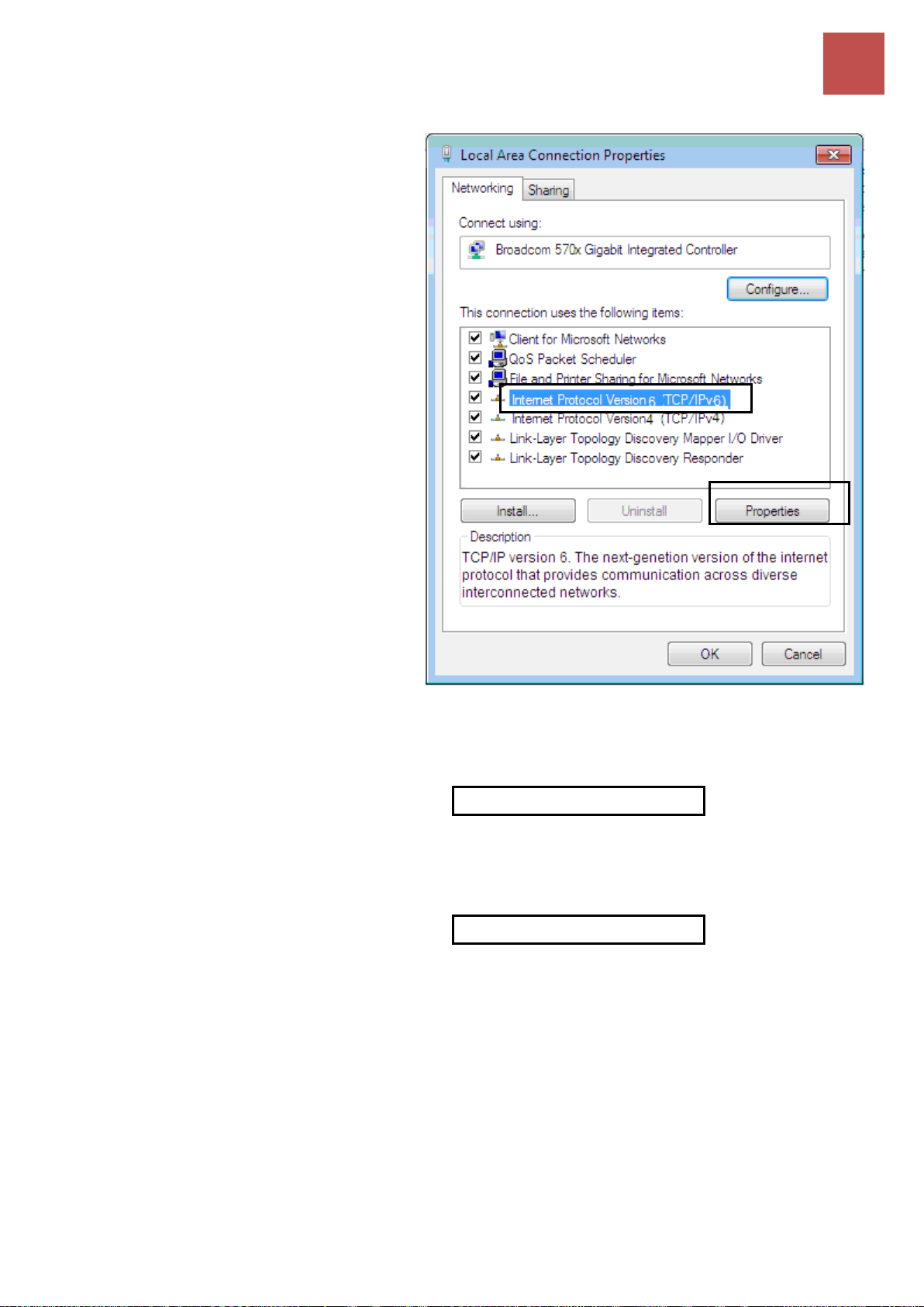
5. Select Internet Protocol Version 6
(TCP/IPv6) then click Properties.
6. In the TCP/IPv6 properties window,
select the Obtain an IP address
automatically and Obtain DNS Server
address automatically radio buttons.
Then click OK to exit the setting.
7. Click OK again in the Local Area
Connection Properties window to
apply the new configuration.
BEC 6500 Series User Manual
Page 37
Basic Installation
Default Settings
31
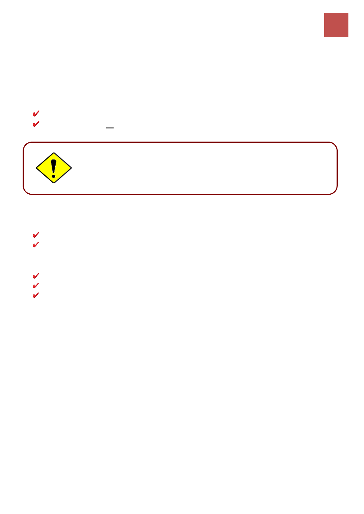
If you ever forget the username/password to login to the router, you may
press the RESET button up to 6 seconds then release it to restore the factory
default settings.
Caution: After pressing the RESET button for more than 6 seconds then
release it, to be sure you power cycle the device again.
Default Settings
Before configuring the router, you need to know the following default settings.
Web Interface: (Username and Password)
Username: admin
Password: admin or a unique 12-digit password can be found on the device label.
Device LAN IP Settings
IP Address: 192.168.1.254
Subnet Mask: 255.255.255.0
DHCP Server:
DHCP server is enabled.
Start IP Address: 192.168.1.100
IP pool counts: 100
BEC 6500 Series User Manual
Page 38

Basic Installation
Information from Your ISP
32
PPPoE
Username, Password, Service Name, and Domain Name
System (DNS) IP address (it can be automatically assigned by
your ISP when you connect or be set manually).
Dynamic IP Address
DHCP Client (it can be automatically assigned by your ISP when
you connect or be set manually).
Static IP Address
IP address, Subnet mask, Gateway address, and Domain Name
System (DNS) IP address (it is fixed IP address).
Bridge Mode
Pure Bridge
Information from Your ISP
Before configuring this device, you have to check with your ISP (Internet Service Provider) what kind of
service is provided such as EWAN ((Dynamic IP address, Static IP address, PPPoE, Bridge Mode).
Gather the information as illustrated in the following table and keep it for reference.
BEC 6500 Series User Manual
Page 39
Device Configuration
Login to GUI
33
CHAPTER 4: DEVICE CONFIGURATION
Login to your Device
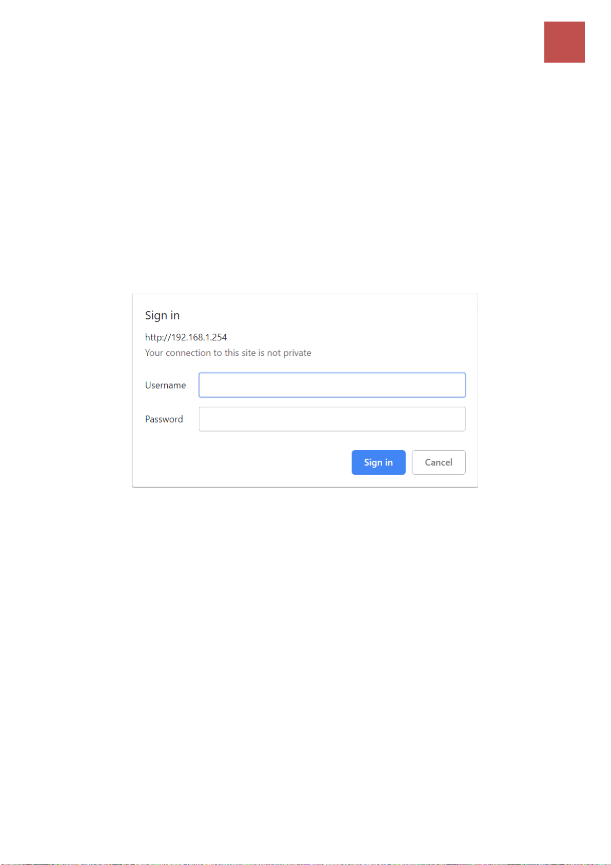
Open your web browser, enter the IP address of your router, which by default is 192.168.1.254, and
click “Go”, a user name and password window prompt appears.
Default username is “admin” and password is “admin” or a unique 12-digit can be found on the
device label for Administrator account.
NOTE: This username / password may vary by different Internet Service Providers.
Congratulations! You have successfully logged on to your BEC 6500.
BEC 6500 Series User Manual
Page 40
Device Configuration
Login to GUI
34
Section
Status
Quick Start
(Wizard Setup)
Configuration
Sub-Items
Device Info
System Status
System Log
4G/LTE Status
Statistics
DHCP Table
IPSEC Status
PPTP Status
L2TP Status
GRE Status
OpenVPN Status
Disk Status
VoIP Status
- VoIP Status
- VoIP Call Log
ARP Table
VRRP
Interface Setup
- Internet
- LAN
- Wireless 2,4G/5G
- Wireless 2.4G/5G MAC Filter
- Loopback
Dual WAN
- General Setting
- Outbound Load Balancing
- Protocol Binding
Advanced Setup
- Firewall
- Routing
- Dynamic Routing
- NAT
- VRRP
- Static DNS
- QoS
- Time Schedule
- Mail Alert
VPN
- IPSec
- PPTP Server & Client
- L2TP
- GRE
- OpenVPN Server / Client
VoIP
- Basic
- Media
- Advanced
- Speed Dial
- Dial Plan
- Call Features
- NAT Traversal
Access Management
- Device Management
- SNMP
- Syslog
- Universal Plug & Play (UPnP)
- Dynamic DNS
- Access Control
- Packet Filter
- CWMP (TR-069)
- Parental Control
- SAMBA & FTP Server
- BECentral Management
Maintenance
- User Management
- Time Zone
- License
- Firmware & Configuration
- System Restart
- Auto Reboot
- Diagnostic Tool
Once you have logged on to your 6500 via your web browser, you can begin to set it up according to
your requirements. On the configuration homepage, the left navigation pane links you directly to the
setup pages, which includes:
Refer to the relevant sections of this manual for detailed instructions on how to configure your device.
BEC 6500 Series User Manual
Page 41

Device Configuration
Status – Device Info
35
Status
In this section, you can check the router working status, including Device Info, System Status,
System Log, 4G/LTE Status, Wireless Status, Hotspot Status, Statistics, DHCP Table, IPSec
Status, PPTP Status, L2TP Status, GRE Status, OpenVPN Status, Disk Status, VoIP Status, ARP
Table and VRRP.
Device Info
It contains basic information of the device.
Device Information
Model Name: Name of the router for identification purpose.
Firmware Version: Software version currently loaded in the router.
MAC Address: A unique number that identifies the router.
Data Time: Setup correct time on the 6500 with your PC. Check on Time Zone section for more
configuration information.
System Uptime: Display how long the 6500 has been powered on.
Physical Port Status
Physical Port Status:Display available connection interfaces supported in the 6500.
WAN
Interface: List current available WAN connections.
Protocol: Display selected WAN connection protocol.
BEC 6500 Series User Manual
Page 42

Device Configuration
Status – Device Info
36
Connection: The current connection status.
IP Address: WAN port IP address.
Default Gateway: The IP address of the default gateway.
LAN
IP Address: LAN port IPv4 address.
Subnet Mask/Prefix Length: Display LAN port IP subnet mask of IPv4 and/or Prefix length of IPv6.
DHCP Server: Display LAN DHCP status of IPv4 and IPv6.
Enable / 192.168.1.100~199: DHCPv4 server status on or off / DHCP IP range.
Enable / Stateless: DHCPv6 server status on or off / DHCPv6 server Type.
Wireless
Mode: Display selected Wireless mode.
SSID: Display the name of the Wireless AP(s) to use.
Channel: Display radio frequency to be used for this wireless link.
Security: Display security method to be used for this wireless link.
BEC 6500 Series User Manual
Page 43
Device Configuration
Status – 4G/LTE Status
37
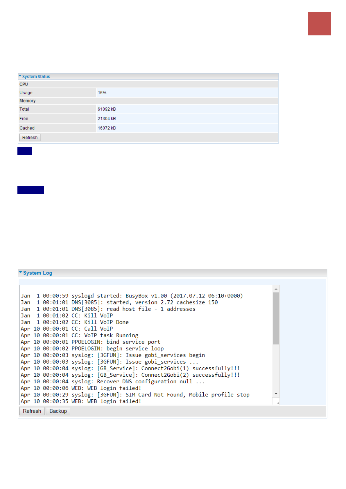
System Status
System status displays the current router system (CPU and Memory) usage.
CPU
Usage: Display the amount of CPU’s processing capacity is being used in percentage (%). Higher the
% rate may result in slow Internet loading, experiencing video lags, etc. To redcue high CPU
consumption by resetting the device, power off and on, an easiest way to regain the service.
Memory
Total / Free / Cached (in Kbyte): Display the memory consumptions in kilobytes (kB).
Click Reflash button to update the status.
System Log
In system log, you can check the operations status and any glitches to the router.
Refresh: Press this button to refresh the statistics.
Backup: Press to save the System log, log.cfg, to your PC.
BEC 6500 Series User Manual
Page 44
Device Configuration
Status – 4G/LTE Status
38
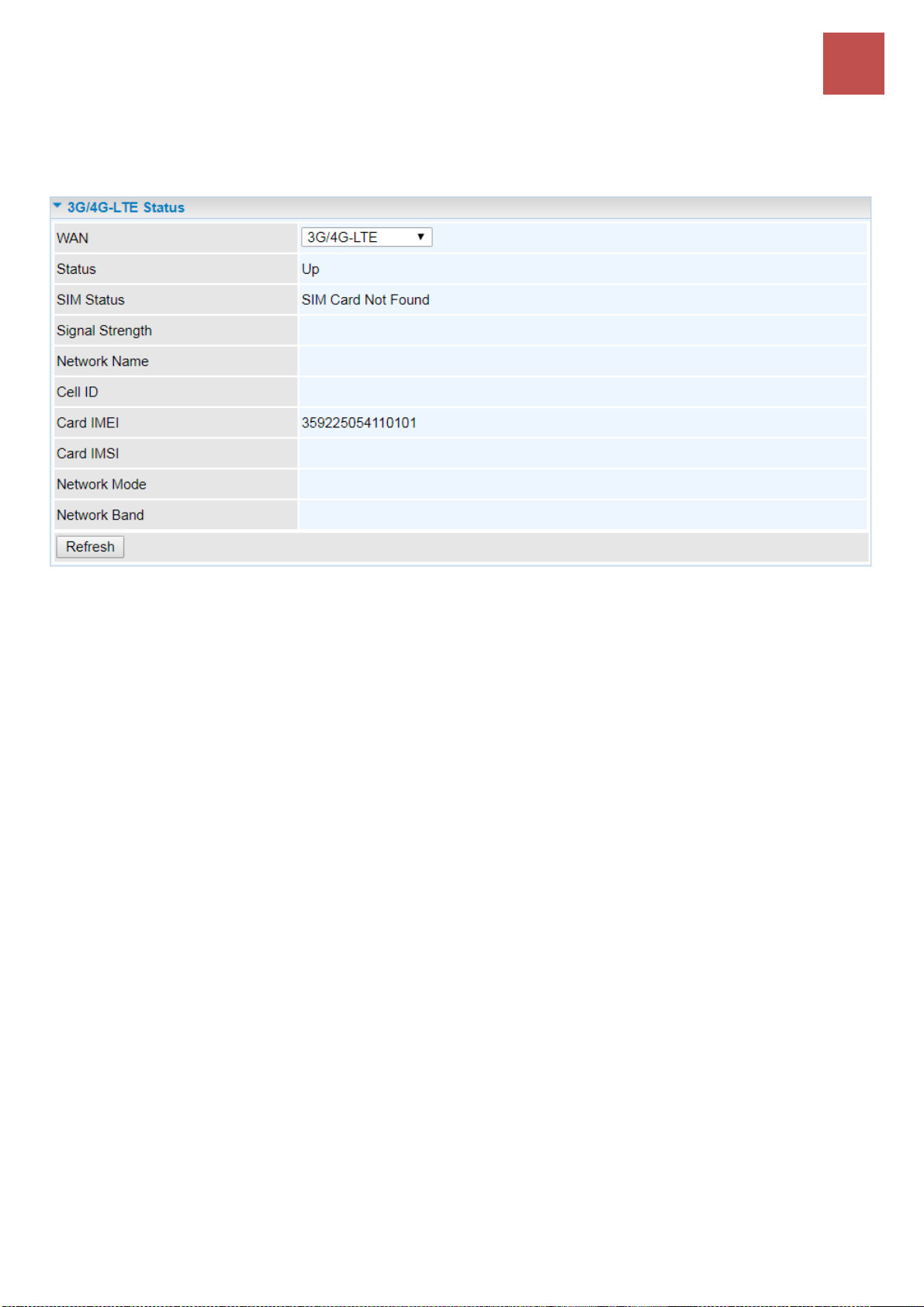
4G/LTE Status
This page contains 4G/LTE connection information.
Status: The current status of the 4G/LTE connection.
SIM Status: Identify current status of the SIM, Activate or SIM Card Not Found.
Signal Strength: The signal strength bar and dBm value indicates the current 4G/LTE signal strength.
The front panel 4G/LTE Signal Strength LED indicates the signal strength as well.
Signal Information: Shows important LTE signal parameters such as RSRP (Reference Signal
Receiving Power), RSRQ (Reference Signal Receiving Quality), SINR (Signal to Interference plus
Noise Ratio).
RSRP (Reference Signal Receiving Power): is the average power of all resource elements
which carry cell-specified reference signals over the entire bandwidth.
RSRQ (Reference Signal Receiving Quality): measures the signal strength and is calculated
based on both RSRP and RSSI.
RSSI (Received Signal Strength Indicator): parameter which provides information about total
received wide-band power (measure in all symbols) including all interference and thermal
noise.
SNR (Signal Noise Ratio): is also a measure of signal quality as well. It is widely used by the
operators as it provides a clear relationship between RF conditions and throughput.
Note: Some LTE modules do not provide this information.
Network Name: The name of the LTE network the router is connecting to.
Cell ID: The ID of base station that the device is connected to.
Card IMEI: The unique identification number that is used to identify the 4G/LTE module.
Card IMSI: The international mobile subscriber identity used to uniquely identify the 4G/LTE module.
Network Mode: Display current network operating mode.
Network Band: Indicated the current radio frequency band used.
Auto Refresh: Select Disable or Enable to reload the mobile status information.
BEC 6500 Series User Manual
Page 45
Device Configuration
Status – 4G/LTE Status
39
Refresh: Click to refresh the statistics.
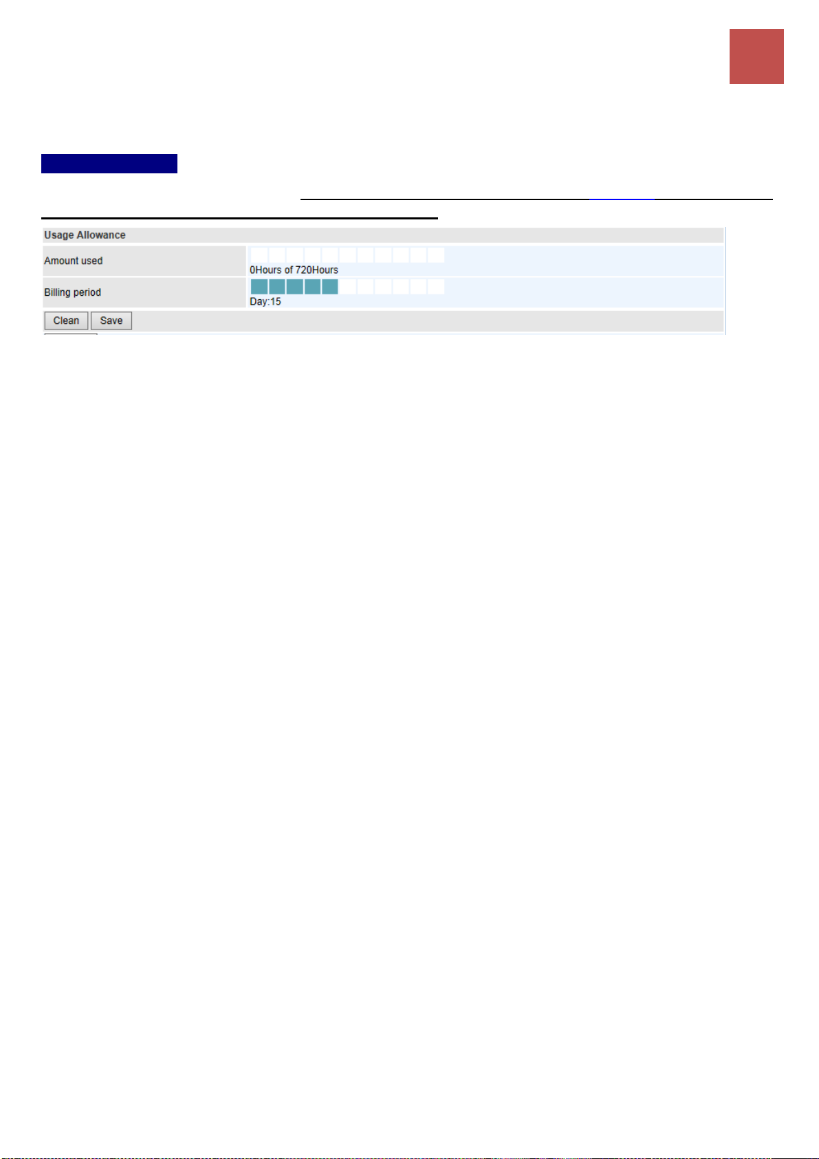
Usage Allowance
To enable this feature, please go to Configuration >> Interface Setup >> Internet >> click “Usage
Allowance” >> enable “Save the statistics to ROM”
Amount Used: Display the amount of mobile data used and remaining in current billing cycle.
Billing Cycle: Display the start date and number of days remaining in current billing cycle
Clean: Reset current saved mobile usage
Save: Click to save current mobile status to ROM
BEC 6500 Series User Manual
Page 46
Device Configuration
Status – Wireless Status
40
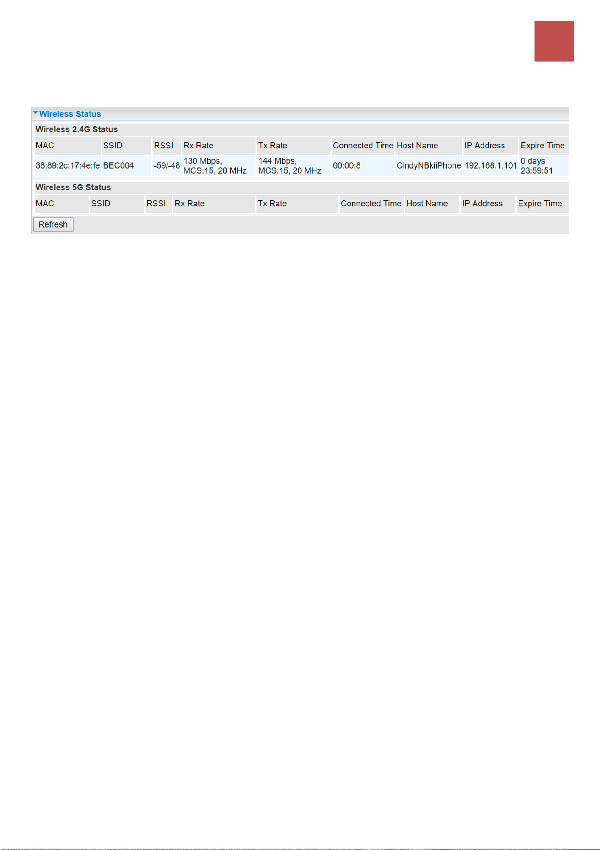
Wireless Status
MAC: The MAC of the connected wireless device.
SSID: Display the total bytes transmitted till the latest second for the current connection for the current
connection.
RSSI: Display the signal strength between the wireless client and the AP (Access Point).
RX / TX Rate: Display the current data reception (RX) and transmission (TX) rate, in Mpbs, of the
Wi-Fi client can use. Also display the MCS (Modulation and Coding Scheme) index and Channel
Bandwidth are used. If 20MHz Channel Bandwidth is bing used, the maximum rate is MCS7 (65Mbps)
or MCS15 (150Mbps). If it is in 40Mhz Channel, then th emaximum rate is MCS7 (150Mbps) or
MCS15 (300Mbps).
Connected Time: Display the total amount of time the wireless client has connected with the wireless
AP.
Host Name: Display the hostname of the Wi-Fi client.
IP Address: The LAN IP address assigned to the wireless device.
Expire Time: Display remaining time before connection expires or timeout.
Refresh: Click to refresh the statistics.
BEC 6500 Series User Manual
Page 47

Device Configuration
Status – Hotspot Status
41
Hotspot Status
The status table displays a list of connected Wi-Fi clients via the hotspot. .
Action: Click Drop to discount the user connection to the Wi-Fi network.
MAC Address: The MAC of the connected wireless device.
IP Address: The LAN IP address assigned to the wireless device.
Authentication: Identification of the wireless device is being authorized or not.
User Name: The authentication username used to login to the hotspot. Go to Built-in User Account for
detailed login account list.
Duration Time (remaining time / available session time interval): Display remaining interval
available before session expires/timeout.
Idle Time (current idle time / total idle timeout period): Display current idle time of the Wi-Fi device.
If it reaches to total idle timeout period, the Internet connection will get disconnected immediately.
Upload / Download (used / available bandwidth in %): Display current used bandwidths, in upload
and download, out of the maximum allow usage in %.
Total Data Usage: Dispaly total data usage of the Wi-Fi user.
BEC 6500 Series User Manual
Page 48
Device Configuration
Status – Statistics (4G/LTE)
42
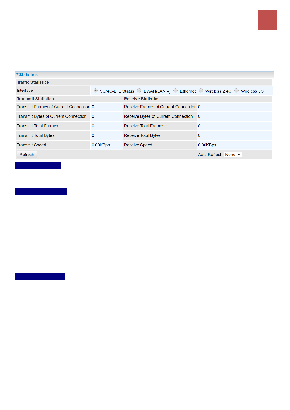
Statistics
❖ 4G/LTE Status
Take 4G/LTE as an example to describe the following connection transmission information.
Traffic Statistics
Interface: List all available network interfaces in the router. You are currently checking on the physical
status of 4G/LTE interface.
Transmit Statistics
Transmit Frames of Current Connection: Display the total number of 4G/LTE frames transmitted
until the latest second for the current connection.
Transmit Bytes of Current Connection: Display the total bytes transmitted till the latest second for
the current connection for the current connection.
Transmit Total Frames: Display the total number of frames transmitted till the latest second since
system is up.
Transmit Total Bytes: Display the total number of bytes transmitted until the latest second since
system is up.
Transmit Speed: Display the data rate can be transferred to the server, the mobile Internet.
Receive Statistics
Receive Frames of Current Connection: Display the number of frames received until the latest
second for the current connection.
Receive Bytes of Current Connection: Display the total bytes received till the latest second for the
current connection.
Receive Total Frames: Display the total number of frames received until the latest second since
system is up.
Receive Total Bytes: Display the total frames received till the latest second since system is up.
Receive Speed: Display the data rate receives from the mobile Internet.
Refresh: Click to manually refresh the data.
Auto Reresh: Select a time interval to refresh the data automatically or none to disable the feature.
BEC 6500 Series User Manual
Page 49

Device Configuration
Status – Statistics (Ethernet)
43
❖ Ethernet WAN (EWAN) on LAN 4
Take 4G/LTE as an example to describe the following connection transmission information.
Traffic Statistics
Interface: List all available network interfaces in the router. You are currently checking on the physical
status of the EWAN (Ethernet #2) port.
Transmit Statistics
Transmit Frames: Display the number of frames transmitted until the latest second.
Transmit Multicast Frames: Display the number of multicast frames transmitted until the latest
second.
Transmit Total Bytes: Display the number of bytes transmitted until the latest second.
Transmit Collision: Numbers of collisions have occurred on this port.
Transmit Error Frames: Display the number of error packets on this port.
Receive Statistics
Receive Frames: Display the number of frames received until the latest second.
Receive Multicast Frames: Display the number of multicast frames received until the latest second.
Receive Total Bytes: Display the number of bytes received until the latest second.
Receive CRC Errors: Display the number of error packets on this port.
Receive Under-size Frames: Display the number of under-size frames received until the latest
second.
Traffic Speed
Transmit Speed: Display the data rate can be transferred to the server, the Broadband Internet
Service Provider.
Receive Speed: Display the data rate receives from the Broadband Internet Service Provider.
Refresh: Click to manually refresh the data.
Auto Reresh: Select a time interval to refresh the data automatically or none to disable the feature.
BEC 6500 Series User Manual
Page 50

Device Configuration
Status – Statistics (Wireless 2.4G & 5G)
44
❖ Wireless (2.4G & 5G)
Traffic Statistics
Interface: List all available network interfaces in the router. You are currently checking on the physical
status of the Wireless 2.4G or Wireless 5G.
Transmit Statistics
Transmit Frames: Display the number of frames transmitted until the latest second.
Transmit Error Frames: Display the number of error frames transmitted until the latest second.
Transmit Drop Frames: Display the number of drop frames transmitted until the latest second.
Receive Statistics
Receive Frames: Display the number of frames received until the latest second.
Receive Error Frames: Display the number of error frames received until the latest second.
Receive Drop Frames: Display the number of drop frames received until the latest second.
Traffic Speed
Transmit Speed: Display the data rate can be transferred to the server, the Wireless AP.
Receive Speed: Display the data rate receives from the Wireless AP.
Refresh: Click to manually refresh the data.
Auto Reresh: Select a time interval to refresh the data automatically or none to disable the feature.
BEC 6500 Series User Manual
Page 51

Device Configuration
Status – DHCP Server & IPSec Status
45
DHCP Table
DHCP table displays the devices connected to the router with clear information.
Index #: The numeric indicator for devices using dynamic IP addresses.
Host Name: Display the hostname of the PC.
IP Address: The IP allocated to the device.
MAC Address: The MAC of the connected device.
Expire Time: The total remaining interval since the IP assignment to the PC.
IPSec Status
Index #: The numeric IPSec VPN tunnel/ rule.
Action: Display Connect or Drop the connection.
Connection Name: The profile name of the VPN connection/tunnel.
Active: Display Yes or No to indicate the profile is enabled or disabled.
Connection State: Display statuses of IPSec phase 1 and phase 2 connections.
Statistics: Display upstream/downstream traffic per session in KB. The value clears when session
disconnects.
Remote Gateway: Display remote gateway IP address.
Remote Network: Display remote local IP address and Netmask.
Local Network: Display local IP address and Netmask.
Refresh: Click to refresh the page.
BEC 6500 Series User Manual
Page 52

Device Configuration
Status – PPTP Status (PPTP Server & PPTP Client)
46
PPTP Status
❖ PPTP Server
Index #: The numeric PPTP VPN tunnel/ rule.
Connection Name: The profile name of the VPN connection/tunnel.
Active: Display Yes or No to indicate the profile is enabled or disabled.
Connection State: Display the VPN connection status.
Connection Type: Display if VPN connection is for single PC use (Remote Access) or multi-user use
(LAN to LAN).
Assigned IP Address: Display the IP address assigned to the client by the PPTP Server.
Remote Network: Display the remote network and subnet mask in LAN to LAN PPTP connection.
Refresh: Click to refresh the page.
❖ PPTP Client
Index #: The numeric PPTP VPN tunnel/ rule.
Connection Name: The profile name of the VPN connection/tunnel.
Active: Display Yes or No to indicate the profile is enabled or disabled.
Connection State: Display Yes/No to indicate the VPN connection status.
Connection Type: Display if VPN connection is for single PC use (Remote Access) or multi-user use
(LAN to LAN).
Server IP Address: Display the WAN IP address of remote PPTP Server.
Remote Network: Display the remote network address and subnet mask in LAN to LAN PPTP
connection.
Refresh: Click to refresh the page.
BEC 6500 Series User Manual
Page 53

Device Configuration
Status – L2TP Status & GRE Status
47
L2TP Status
Index #: The numeric L2TP VPN tunnel/rule indicator.
Connection Name: The profile name of the VPN connection/tunnel.
Active: Display Yes or No to indicate the profile is enabled or disabled.
Connection State: Display Yes/No to indicate the VPN connection status.
Connection Mode: Display if L2TP mode is a dial-in or dial-out.
Connection Type: Display if VPN connection is for single PC use (Remote Access) or multi-user use
(LAN to LAN).
Tunnel Remote IP Address: Display the remote tunnel IP address.
Refresh: Click to refresh the page.
GRE Status
Index #: The numerical GRE tunnel/rule indication.
Connection Name: The profile name of the VPN connection/tunnel.
Active: Display Yes or No to indicate the profile is enabled or disabled.
Connection State: Display Yes/No to indicate the VPN connection status.
Remote Gateway IP: Display the remote gateway IP address.
Remote Network: Display the remote local network IP address / Netmask.
BEC 6500 Series User Manual
Page 54
Device Configuration
VoIP Status
48
VoIP Status
❖ VoIP Status
VoIP status gives you a directive picture on the registered VoIP accounts.
Phone Number: The number you use to register in the Basic page of VoIP.
Host: Show the IP address and port number of SIP Registrar.
Status: The status of the registered SIP account.
Registered Time: The duration the account has been successfully registered to the SIP registrar.
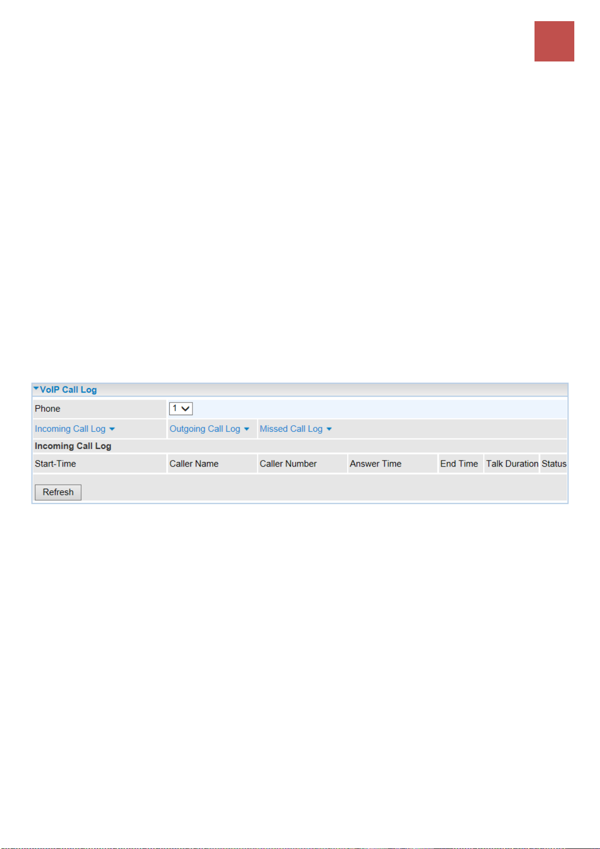
❖ VoIP Call Log
VoIP call log records all inbound / outbound calls in detail within your VoIP accounts. You can quickly
view the call date, time, incoming/outgoing/missed call telephone number, and more.
Phone Number: The number you use to register in the Basic page of VoIP.
Incoming / Outgoing / Miss Call Log: Click the call log you want to view.
Start-Time: The start time of the call
Caller/Called Name: Display the caller ID of the dialing party / the party you dialed to reach to.
Caller/Called Number: Display caller telephone number / telephone number you dialed to reach to
Answer Time: The answer time of phone call
End Time: The end time of the call
Talk Duration: Time duration of individual calls from dial/call to hang-up.
Status: Current call status if phones are off hook or in a call.
BEC 6500 Series User Manual
Page 55
Device Configuration
Disk Status / ARP Table / VRRP Status
49
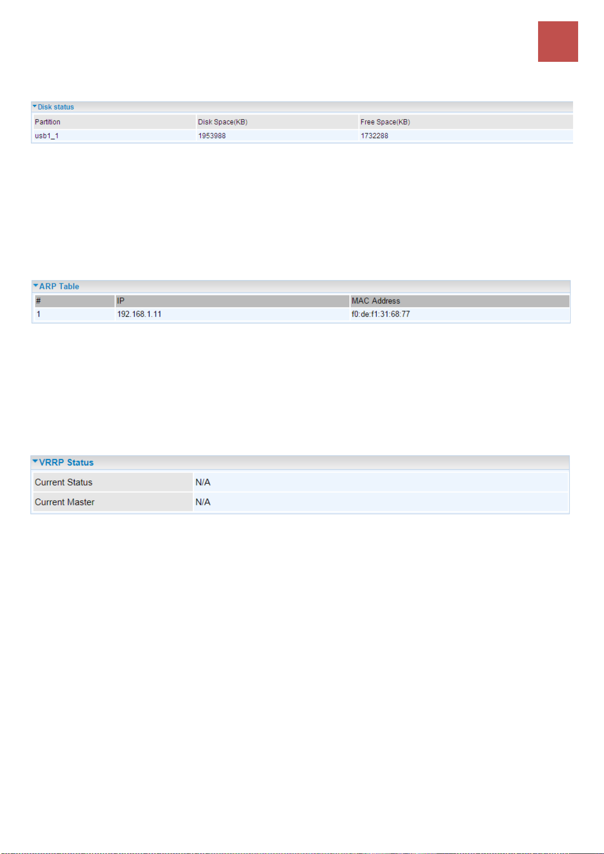
Disk Status
Partition: Display the USB storage partition.
Disk Space (KB): Display the total storage space of the NAS in Kbytes unit.
Free Space (KB): Display the available space in Kbytes unit.
ARP Table
ARP (Address Resolution Protocol) table displays a mapping IP address with a PC’s MAC address.
#: The numeric table list indicator.
IP Address: It is the internal/local IP address to access to the network.
MAC Address: The MAC address of a device, e.g. PC, notebook, printer, etc., that is corresponded
with the IP address.
VRRP Status
Current Status: Display current VRRP status, Master or Backup.
Current Master: Display the IP address of the Master.
BEC 6500 Series User Manual
Page 56
Device Configuration
Quick Start
50
Quick Start
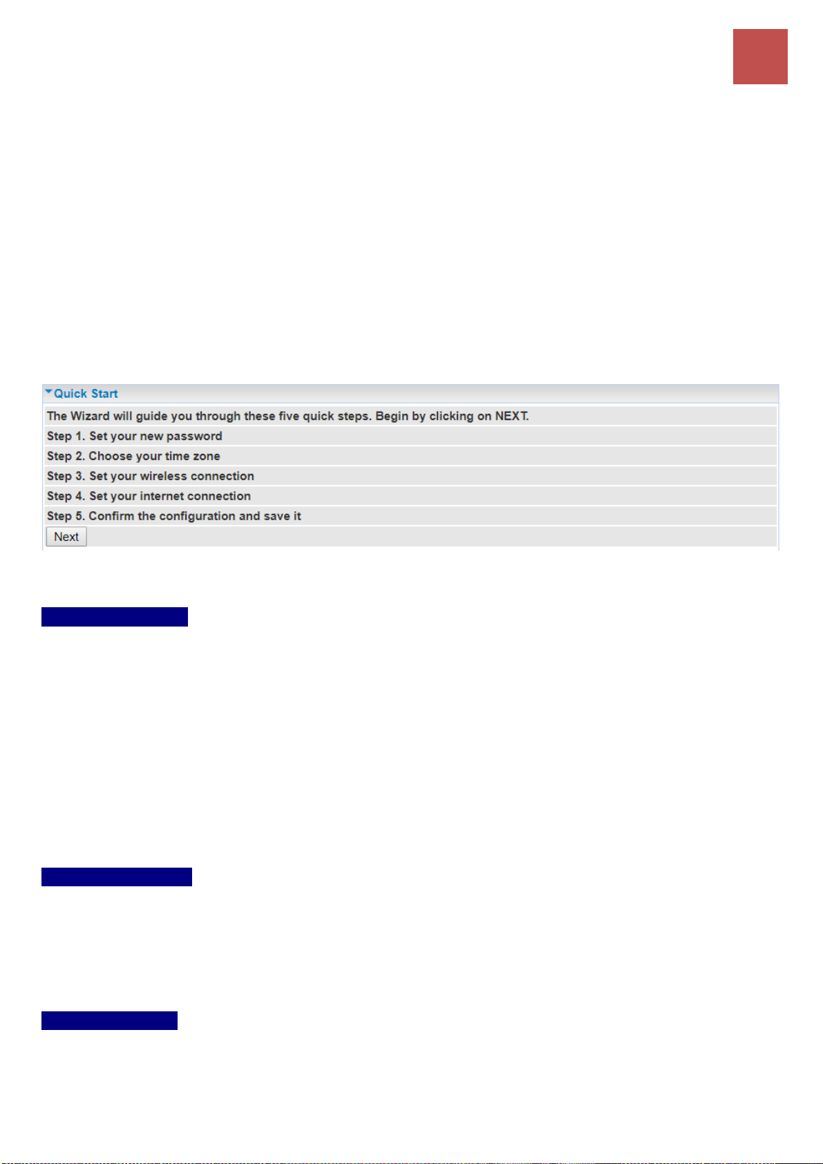
This is a useful and easy utility to help you to setup the router quickly and to connect to your ISP
(Internet Service Provider) with only a few steps. It will guide you step by step to setup time zone and
WAN settings of your device. The Quick Start Wizard is a helpful guide for the first-time users to the
device.
For detailed instructions on configuring WAN settings, see refer to the Interface Setup section.
Click NEXT to move on to Step 1.
Step 1 – Password
Set new password of the “admin” account to access for router management. The default is “admin”, or
a unique 12-digit password can be found on the device label.
Once changed, please use this new password next time when accessing to the router. Click NEXT to
continue.
Step 2 – Time Zone
Choose your time zone. Click NEXT to continue.
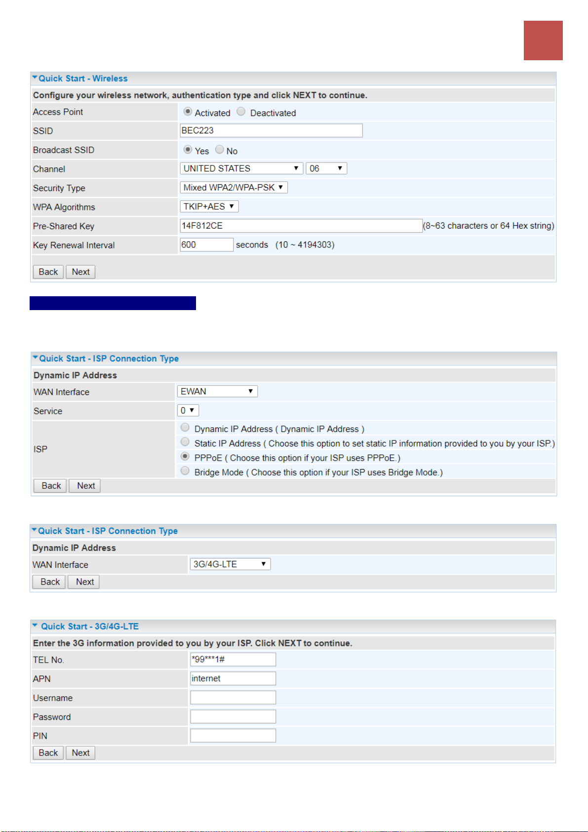
Step 3 – Wireless
Set up your wireless connection if you want to connect to the Internet wirelessly on your PCs. Click
NEXT to continue.
BEC 6500 Series User Manual
Page 57
Device Configuration
Quick Start
51
Step 4 – ISP Connection Type
Set up your Internet connection.
4.1 Select an appropriate WAN connection protocol then click NEXT to continue.
4.2 If selected 4G/LTE (for example).
Input all relevant 4G/LTE parameters from your ISP.
Click Next to save changes.
BEC 6500 Series User Manual
Page 58
Device Configuration
Quick Start
52
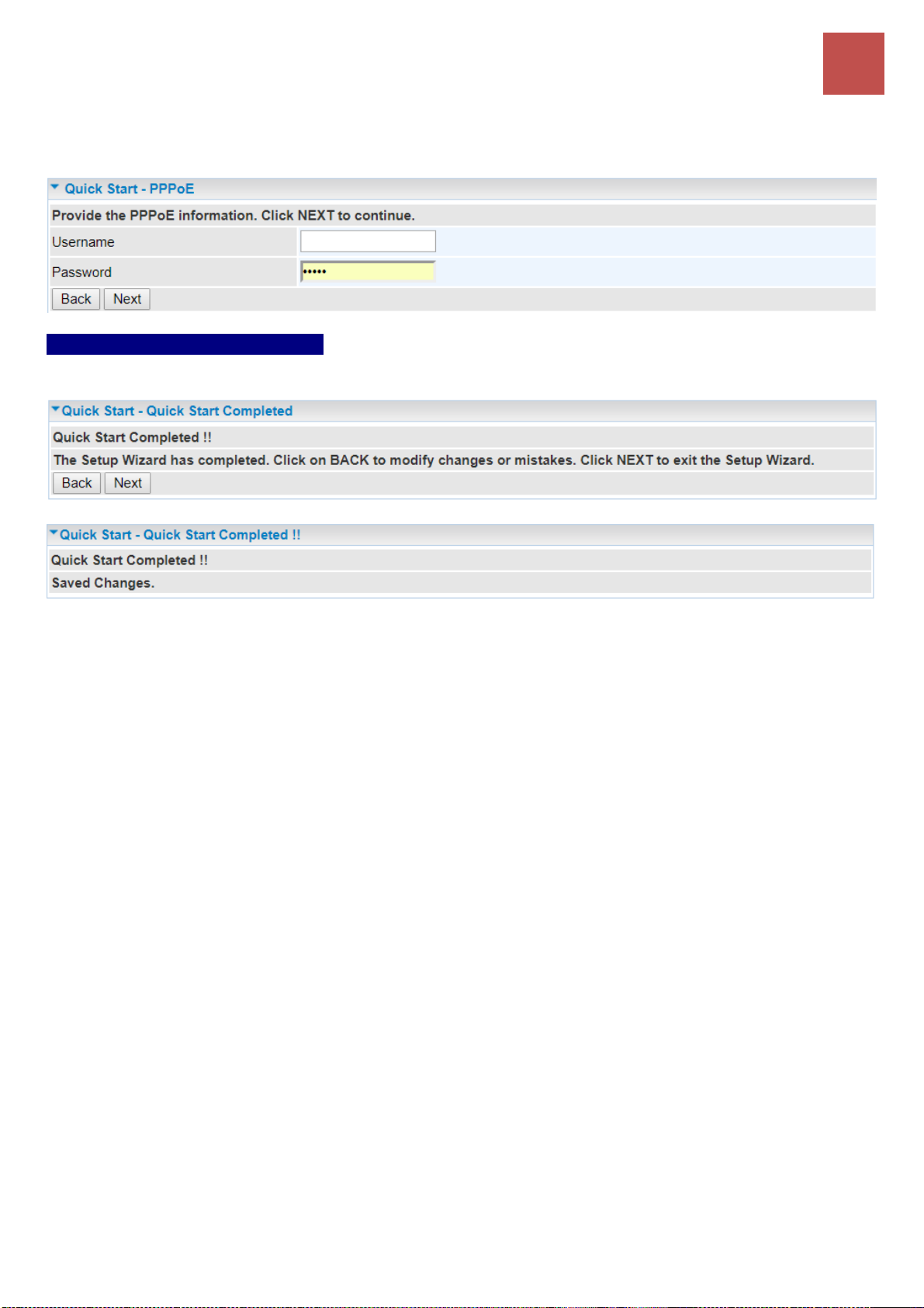
4.2 If selected EWAN / PPPoE, please enter PPPoE account information provided by your ISP. Click
NEXT to continue.
Step 5 – Quick Start Completed
The Setup Wizard has completed. Click on BACK to modify changes or mistakes. Click NEXT to save
the current settings.
Switch to Status > Device Info to view the status.
BEC 6500 Series User Manual
Page 59

Device Configuration
Interface Setup – Internet (4G/LTE)
53
Device Configuration
Click to access and configure the available features in the following: Interface Setup, Dual WAN,
Hotspot, Advanced Setup, Access Management and Maintenance.
These functions are described in the following sections.
Interface Setup
Here are the features under Interface Setup: Internet, LAN, Wireless 2.4G/5G, Wireless MAC Filter
2.4G / 5G and Loopback
Internet
Available Internet interfaces are Ethernet WAN (EWAN) and 4G/LTE
❖ 4G/LTE
BEC 6500 Series User Manual
Page 60

Device Configuration
Interface Setup – Internet (4G/LTE)
54
❖ 4G/LTE (Cont.)
Status: Choose Activated to enable the 4G/LTE connection.
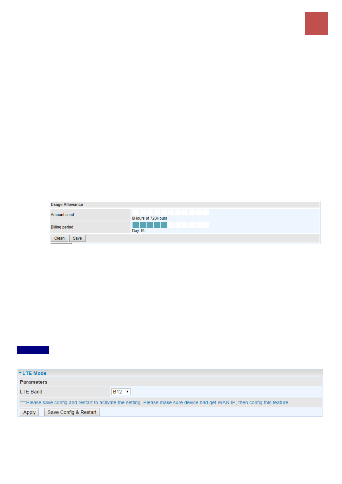
Usage Allowance
Mode: Include Volume-based and Time-based control.
Volume-based include “only Download”, "only Upload”, and “Download and Upload” to limit
BEC 6500 Series User Manual
Page 61
Device Configuration
Interface Setup – Internet (4G/LTE)
55
the flow.
Time-based control the flow by providing specific hours per month.
The billing period begins on: the beginning day of billing each month.
Over usage allowance action: Here are actions to perform when mobile data usage, defined in
Mode, reached to its maximum.
None: No action taken
Disconnect: Disconnect mobile connection
Email Alert: Send an e-mail alert and keep the mobile connection alive.
Email Alert and Disconnect: Disconnect mobile connection after an alert e-mail is being
sent.
Save the statistics to ROM:
Every one hour: Activate the 4G/LTE statistics on data usage and this info will get updated
and saved to the internal memory (ROM) in every hour.
Once the feature is turned on, you can see the amount of data used and how many days left
before next billing cycle starts. Go to Status >> 4G/LTE Status page for details.
NOTE: This statistic information will get deleted after a factory reset.
Disable: No action taken
IP Pass-Through Mode: When enabled, BEC 6500 is in bridge mode and will not obtain a WAN IP
address, features such as routing capabilities, NAT, firewall, etc., will be disabled by default. However,
the client router behind the BEC 6500 can get a WAN IP address instead.
When disabled, BEC 6500 is in router mode that it handles a WAN IP address and all routing-related
features become available.
Network Mode: Select Automatic to auto detect the best mode for you.
LTE Mode (Only available on selected LTE Modules): Display current selected LTE frequency band.
To change the band, please click “LTE Band” to access to the band selection page.
LTE Band
LTE Band: A list of available LTE bands to choose from.
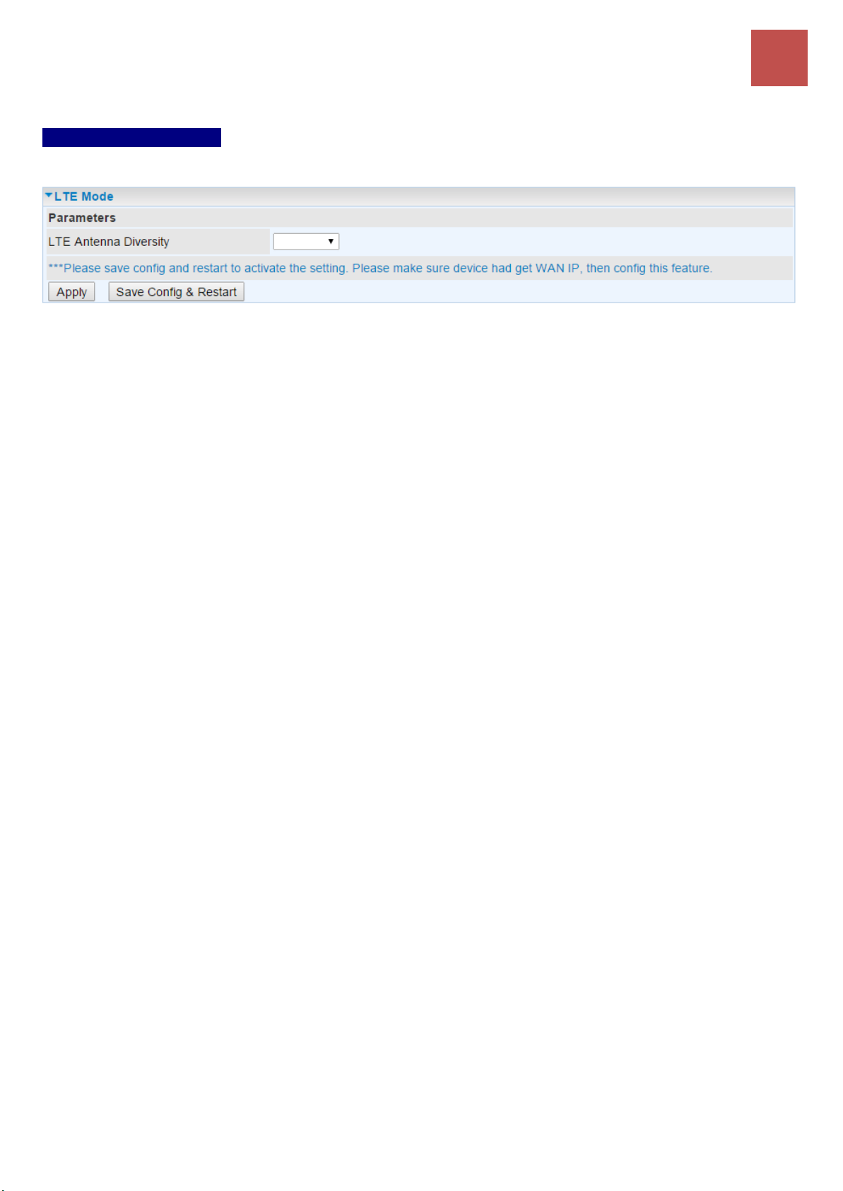
LTE Antenna Diversity (Only available on selected LTE Modules): When enabled, the auxiliary
antenna will be activated. With disabled, only the primary antenna is receiving and transmitting data.
To change it, please click “LTE Antenna Diversity” to access to the LTE antenna diversity selection
page.
BEC 6500 Series User Manual
Page 62
Device Configuration
Interface Setup – Internet (4G/LTE)
56
NOTE: When using Yagi antenna, please DISABLE the Antenna Diversity feature for utmost performance.
LTE Antenna Diversity
To enable or disable the LTE antenna diversity feature.
PLMN (Public Land Mobile Network) Selection: Either manually enter the information or click Scan
button to scanning all closest base stations in the area.
TEL No.: The dial string to make a GPRS / 4G/LTE user internetworking call. It may provide by your
mobile service provider.
Dual APN*(This feature is not supported in some LTE modules): BEC 6500 can support up to two (2)
APNs. Select Single / Dual or a different LTE APN.
APN: An APN is similar to a URL on the WWW, it is what the unit makes a GPRS / UMTS call. The
service provider is able to attach anything to an APN to create a data connection, requirements for
APNs varies between different service providers. Most service providers have an internet portal which
they use to connect to a DHCP Server, thus giving you access to the internet i.e. some mobile
operators use the APN ‘internet’ for their portal. The default value is “internet”.
PDN Type: The IP type for PDN connections. Avaialbe types are IPv4, IPv6, and IPv4v6.
Username/Password: Enter the username and password provided by your service provider. The
username and password are case sensitive.
PIN: PIN stands for Personal Identification Number. A PIN code is a numeric value used in certain
systems as a password to gain access and authenticate. In mobile phones a PIN code locks the SIM
card until you enter the correct code. If you enter the PIN code incorrectly into the phone 3 times in a
row, then the SIM card will be blocked, and you will require a PUK code from your network/service
provider.
Connection: Default set to Always on to keep an always-on 4G/LTE connection.
Keep Alive: Select Yes to keep the 4G/LTE connection always on.
Keep Alive IP: Enter the IP address that the router can ping the IP to find whether the connection is on
or not, if not, router will recover the connection.
Default Route: Select Yes to use this interface as default route interface.
NAT: Select this option to Disabled/Enable the NAT (Network Address Translation) function. Enable
NAT to grant multiples devices in LAN to access to the Internet through a single WAN IP.
MTU: Enter the maximum packet that can be transmitted. Default MTU 0 means it is set to 1500 bytes.
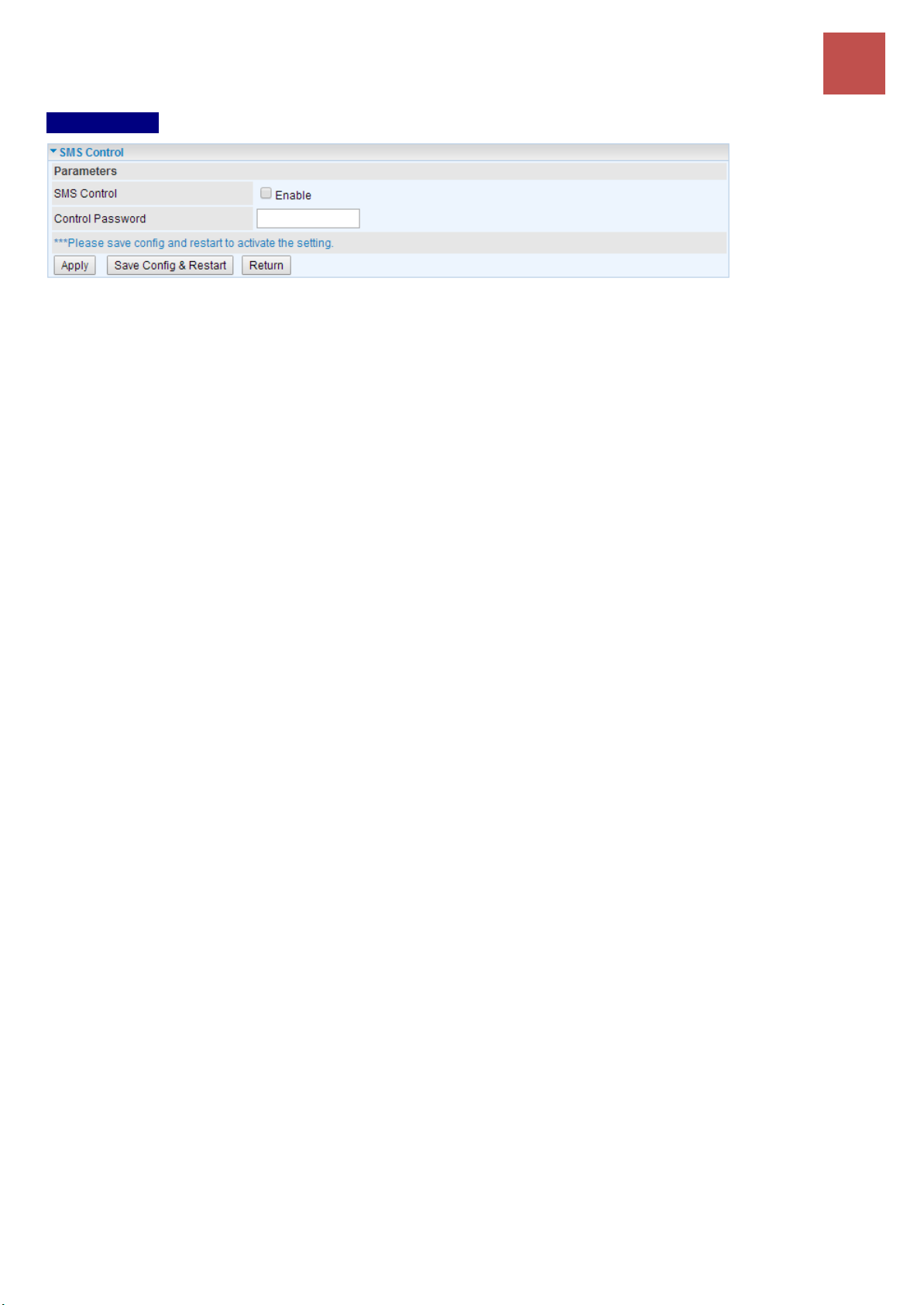
SMS Control (Only available on selected LTE Modules): Enable to send a SMS message to reboot or
get the current 4G/LTE status information from the 6500.
NOTE: You must obtain the phone number on the SIM card. Please contact with your network / service provider for more
information.
BEC 6500 Series User Manual
Page 63
Device Configuration
Interface Setup – Internet (4G/LTE)
57
SMS Control
SMS Control: Check to enable this feature.
Control Password: Preconfigure a password to automatically reboot your BEC 6500 via a SMS
message. Password length is up to 10 characters. (Valid characters: 0~9, A~Z and a~z)
Example:
Your BEC 6500 obtains the phone number, +513 123 4567, on the SIM card
1. Send a text message, reboot#<password>, to device (513 123 4567). Your BEC 6500 will reboot
the system once receiving this message.
2. Send *60, will get 4G/LTE status message. It includes IMEI number, System up time, Network mode,
Signal strength, WAN IP, Connection time.
When router’s Internet configuration is finished successfully, you can go to the Status to check
connection information.
BEC 6500 Series User Manual
Page 64

Device Configuration
Interface Setup – Internet (EWAN on LAN4)
58
❖ EWAN
Status: Select to enable/activate or disable/deactivated the service.
IPv4/IPv6
IP Version: Choose IPv4, IPv4/IPv6, IPv6 based on your environment. If you don’t know which one to
choose from, please choose IPv4/IPv6 instead.
ISP Connection Type:
ISP: Select the encapsulation type your ISP uses.
Dynamic IP: Select this option if your ISP provides you an IP address automatically.
BEC 6500 Series User Manual
Page 65

Device Configuration
Interface Setup – Internet (EWAN on LAN4)
59
Static IP: Select this option to set static IP information. You will need to enter in the Connection
type, IP address, subnet mask, and gateway address, provided to you by your ISP. Each IP
address entered in the fields must be in the appropriate IP form. IP address from by four IP
octets separated by a dot (xx.xx.xx.xx). The Router will not accept the IP address if it is not in
this format.
PPPoE: Select this option if your ISP requires you to use a PPPoE connection.
Bridge: Select this mode if you want to use this device as an OSI Layer 2 device like a switch.
802.1q Options
802.1q: When activated, please enter a VLAN ID.
VLAN ID: It is a parameter to specify the VLAN which the frame belongs. Enter the VLAN ID
identification, tagged: 0-4095.
PPPoE (If selected PPPoE as WAN Connection Type; otherwise, skip this part)
Username: Enter the user name provided by your ISP.
Password: Enter the password provided by your ISP.
Bridge Interface for PPPoE: When “Activated”, the device will gain WAN IP from your ISP with the
PPPoE account. But if your PC is connected to the router working as a DHCP client, in this mode, the
device acts as a NAT router; while if you dial up with the account within your PC, the device will then
work as a bridge forwarding the PPPoE information to the PPPoE server and send the response to
your PC, thus your PC gets a WAN IP working in the internet.
Connection Setting
Connection:
Always On: Click on Always On to establish a PPPoE session during start up and to
automatically re-establish the PPPoE session when disconnected by the ISP.
Connect Manually: Select Connect Manually when you don't want the connection up all the
time.
TCP MSS Option: Enter the maximum size of the data that TCP can send in a segment. Maximum
Segment Size (MSS).
IP Common Options
Default Route: Select Yes to use this interface as default route interface.
TCP MTU Option: Enter the maximum packet that can be transmitted. Default MTU 0 means it is set
to 1492 bytes.
IPv4 Options
Get IP Address: Choose Static or Dynamic
Static IP Address: If Static is selected in the above field, please enter the specific IP address you get
from ISP and the following IP subnet mask and gateway address.
BEC 6500 Series User Manual
Page 66

Device Configuration
Interface Setup – Internet (EWAN on LAN4)
60
IP Subnet Mask: The default is 0.0.0.0. User can change it to other such as 255.255.255.0.Type the
subnet mask assigned to you by your ISP (if given).
Gateway: Enter the specific gateway IP address you get from ISP.
NAT: Select Enable if you use this router to hold a group of PCs to get access to the internet.
Dynamic Route:
RIP Version: (Routing Information protocol) Select this option to specify the RIP version,
including RIP-1, RIP-2.
RIP Direction: Select this option to specify the RIP direction.
- None is for disabling the RIP function.
- Both means the router will periodically send routing information and accept routing
information then incorporate into routing table.
- IN only means the router will only accept but will not send RIP packet.
- OUT only means the router will only send but will not accept RIP packet.
IGMP Proxy: IGMP (Internet Group Multicast Protocol) is a network-layer protocol used to establish
membership in a Multicast group. Choose whether enable IGMP proxy.
IPv6 options (only when choose IPv4/IPv6 or just IPv6 in IP version field above):
IPv6 Address: Type the WAN IPv6 address from your ISP.
Obtain IPv6 DNS: Choose if you want to obtain DNS automatically.
Primary/Secondary: if you choose Disable in the Obtain IPv6 DNS field, please type the exactly
primary and secondary DNS.
MLD Proxy: MLD (Multicast Listener Discovery Protocol) is to IPv6 just as IGMP to IPv4. It is a
Multicast Management protocol for IPv6 multicast packets.
BEC 6500 Series User Manual
Page 67

Device Configuration
Interface Setup – LAN
61
LAN
A Local Area Network (LAN) is a shared communication system to which many computers are
attached and is limited to the immediate area, usually the same building or floor of a building.
BEC 6500 Series User Manual
Page 68

Device Configuration
Interface Setup – LAN
62
IPv4 Parameters
IP Address: Enter the IP address of Router in dotted decimal notation, for example, 192.168.1.254
(factory default).
IP Subnet Mask: The default is 255.255.255.0. User can change it to other such as 255.255.255.128.
Alias IP Address: This is for local networks virtual IP interface. Specify an IP address on this virtual
interface.
Alias IP Subnet Mask: Specify a subnet mask on this virtual interface.
IGMP Snooping: Select Activated to enable IGMP Snooping function, Without IGMP snooping,
multicast traffic is treated in the same manner as broadcast traffic - that is, it is forwarded to all ports.
With IGMP snooping, multicast traffic of a group is only forwarded to ports that have members of that
group.
Dynamic Route:
RIP Version: (Routing Information protocol) Select this option to specify the RIP version,
including RIP-1, RIP-2.
RIP Direction: Select this option to specify the RIP direction.
- None is for disabling the RIP function.
- Both means the router will periodically send routing information and accept routing
information then incorporate into routing table.
- IN only means the router will only accept but will not send RIP packet.
- OUT only means the router will only send but will not accept RIP packet.
DHCPv4 Server
DHCP (Dynamic Host Configuration Protocol) allows individual clients to obtain TCP/IP configuration
at start-up from a server.
DHCPv4 Server: If set to Enabled, your BEC 6500 can assign IP addresses, default gateway and
DNS servers to the DHCP client.
If set to Disabled, the DHCP server will be disabled.
If set to Relay, the BEC 6500 acts as a surrogate DHCP server and relays DHCP requests and
responses between the remote server and the clients. Enter the IP address of the actual, remote
DHCP server in the Remote DHCP Server field in this case.
BEC 6500 Series User Manual
Page 69
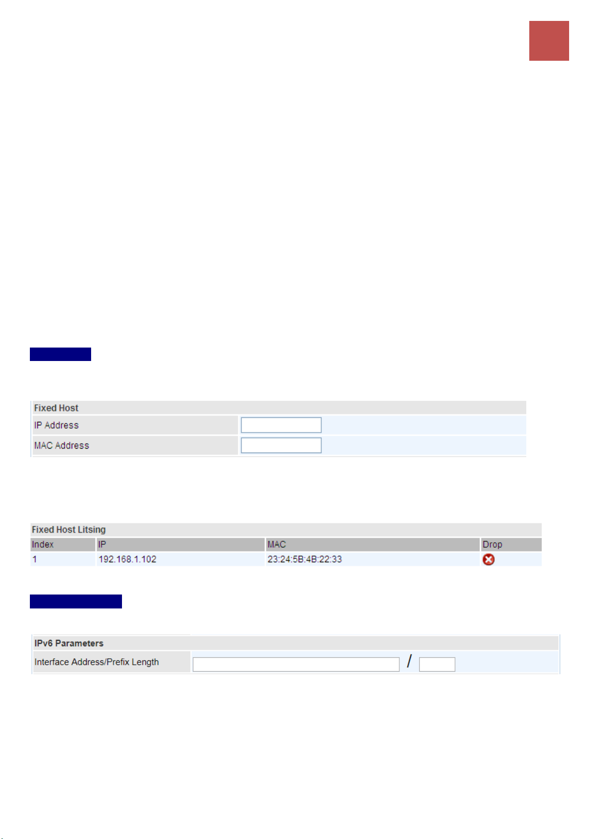
Device Configuration
Interface Setup – LAN
63
When DHCP is used, the following items need to be set.
Start IP: This field specifies the first of the contiguous addresses in the IP address pool.
IP Pool Count: This field specifies the count of the IP address pool.
Lease Time: The current lease time of client.
DNS Relay:
Select Automatic detection or
Manually specific Primary and Secondary DNS IP addresses
Primary / Secondary DNS Server: Enter the IP addresses of the DNS servers. The DNS servers are
passed to the DHCP clients along with the IP address and the subnet mask.
Option 66: Set the IP or hostname of the TFTP server for devices, like IPTV Set Box, to get
configuration settings from the TFTP server.
Option 160: Set the IP or hostname of the TFTP server for devices, like IPTV Set Box, to get
configuration settings from the TFTP server. (The option 160 is an extended feature in DHCP option,
similar to option 66, but using http or https protocols.)
Fixed Host
In this field, users can map the specific IP (must in the DHCP IP pool) for some specific MAC, and this
information can be listed in the following table.
IP Address: Enter the specific IP. For example: 192.168.1.110.
MAC Address: Enter the responding MAC. For example: 00:0A:F7:45:6D:ED
When added, you can see the ones listed as showed below:
IPv6 parameters
The IPv6 address composes of two parts, thus, the prefix and the interface ID.
Interface Address / Prefix Length: Enter a static LAN IPv6 address. If you are not sure what to do
with this field, please leave it empty as if contains false information it could result in LAN devices not
being able to access other IPv6 device. Router will take the same WAN’s prefix to LAN side if the field
is empty.
BEC 6500 Series User Manual
Page 70
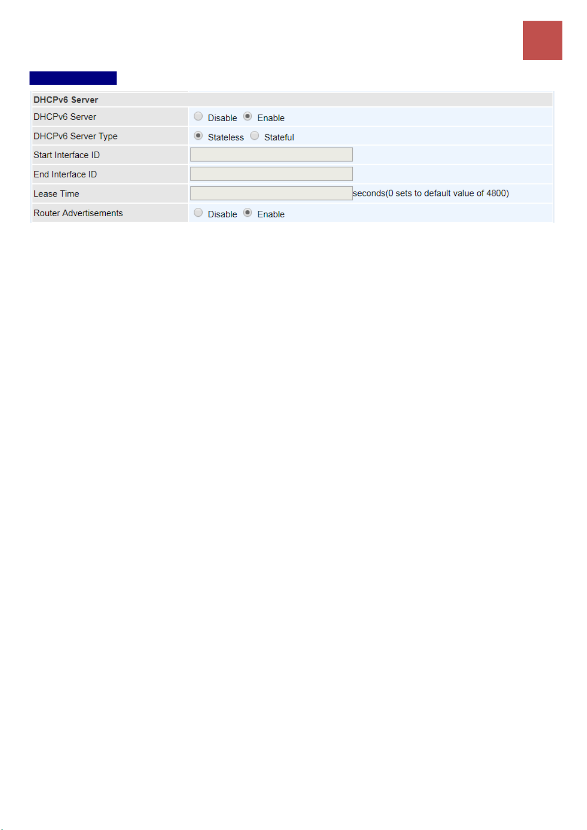
Device Configuration
Interface Setup – LAN
64
DHCPv6 Server
There are two methods to dynamically configure IPv6 address on hosts, Stateless and Stateful.
Stateless auto-configuration requires no manual configuration of hosts, minimal (if any)
configuration of routers, and no additional servers. The stateless mechanism allows a host to generate
its own addresses using a combination of locally available information (MAC address) and information
(prefix) advertised by routers. Routers advertise prefixes that identify the subnet(s) associated with a
link, while hosts generate an "interface identifier" that uniquely identifies an interface on a subnet. An
address is formed by combining the two. When using stateless configuration, you needn’t configure
anything on the client.
Stateful configuration, for example using DHCPv6 (which resembles its counterpart DHCP in IPv4.)
In the stateful auto configuration model, hosts obtain interface addresses and/or configuration
information and parameters from a DHCPv6 server. The Server maintains a database that keeps track
of which addresses have been assigned to which hosts.
DHCPv6 Server: Check whether to enable DHCPv6 server.
DHCPv6 Server Type: Select Stateless or Stateful. When DHCPv6 is enabled, this parameter is
available.
Stateless: If selected, the PCs in LAN are configured through RA mode, thus, the PCs in LAN
are configured through RA mode, to obtain the prefix message and generate an address using a
combination of locally available information (MAC address) and information (prefix) advertised
by routers, but they can obtain such information like DNS from DHCPv6 Server.
Stateful: If selected, the PCs in LAN will be configured like in IPv4 mode, thus obtain addresses
and DNS information from DHCPv6 server.
Start interface ID: enter the start interface ID. The IPv6 address composed of two parts, thus, the
prefix and the interface ID. Interface is like the Host ID compared to IPv4.
End interface ID: enter the end interface ID.
Leased Time (hour): the leased time, similar to leased time in DHCPv4, is a time limit assigned to
clients, when expires, the assigned ID will be recycled and reassigned.
Router Advertisement: Check to Enable or Disable the Issue Router Advertisement feature. This
feature is to send Router Advertisement messages periodically which would multicast the IPv6 Prefix
information (similar to v4 network number 192.168.1.0) to all LAN devices if the field is enabled. We
suggest enabling this field.
Click Save to apply settings.
BEC 6500 Series User Manual
Page 71

Device Configuration
Interface Setup – Wireless 2.4GHz & 5GHz
65
Wireless 2.4GHz & 5GHz
This section introduces the wireless LAN and some basic configurations. Wireless LANs can be as
complex as a number of computers with wireless LAN cards communicating through access points
which bridge network traffic to the wired LAN.
NOTE: WLAN1 / 2 / 3 / 4 Interface refers to as SSID1 / 2 / 3 / 4 Wi-Fi networks.
Access Point Settings
Site Survey: Click to view all other available Wireless-AP devices near the BEC 6500.
CH (Channel): Channel ID used.
SSID: The name of the wireless AP.
BSSID: The MAC address of the wireless AP.
Security: The security mode in the wireless AP.
Singal (%): Singal strength of the wireless AP. Signal incrases means the wireless AP is closer
to your BEC 6500 and may cause interferences.
Access Point: Default setting is set to Activated. If you want to close the wireless interface, select
Deactivated.
AP MAC Address: The MAC address of wireless AP.
Wireless Mode: The default setting is 802.11b+g+n (Mixed mode). If you do not know or have both
11g and 11b devices in your network, then keep the default in mixed mode. From the drop-down
BEC 6500 Series User Manual
Page 72
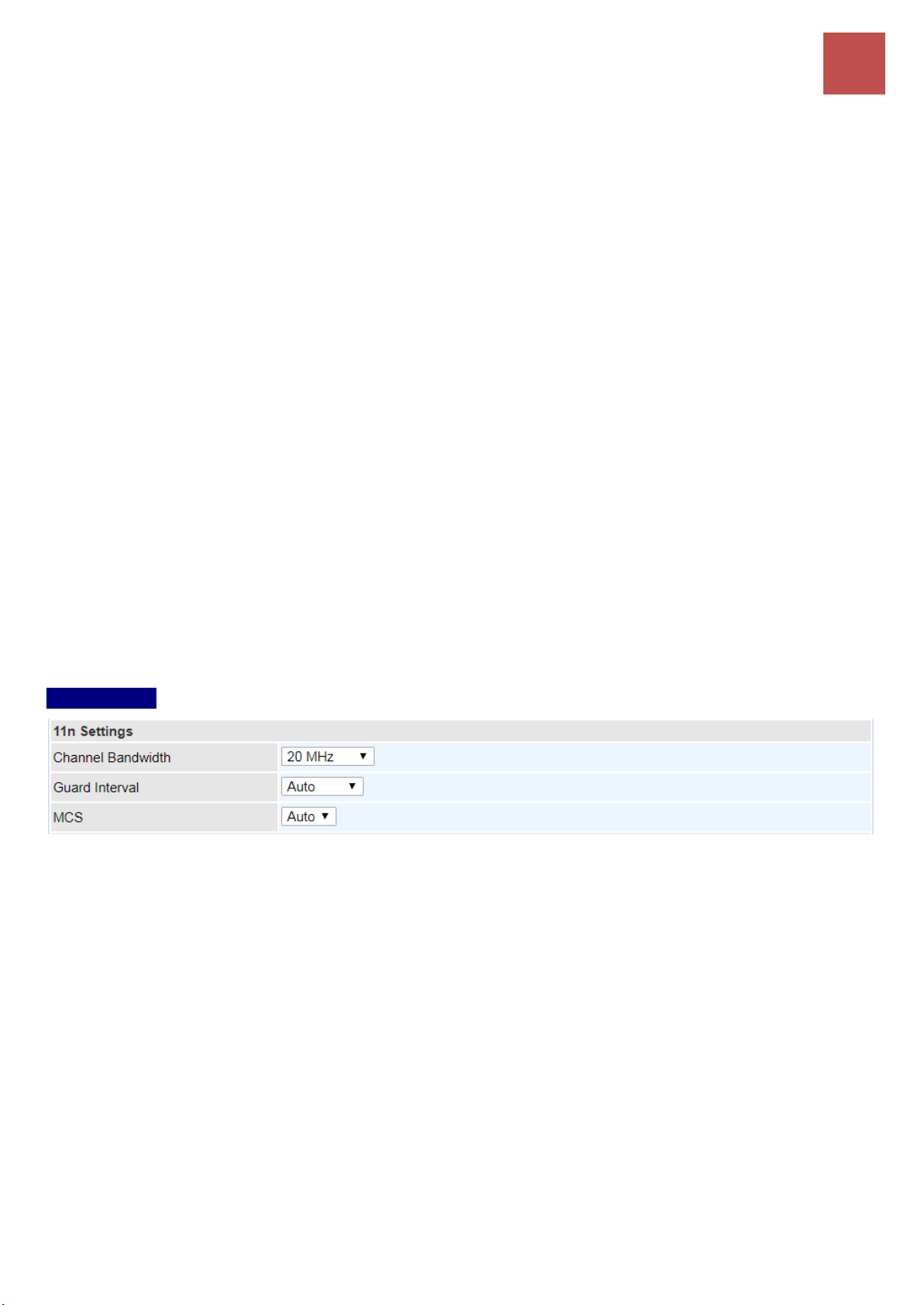
Device Configuration
Interface Setup – Wireless 2.4GHz & 5GHz
66
manual, you can select 802.11g if you have only 11g card. If you have only 11b card, then select
802.11b and if you only have 802.11n then select 802.11n.
Channel: The range of radio frequencies used by IEEE 802.11b/g/n wireless devices is called a
channel. There are Regulation Domains and Channel ID in this field. The Channel ID will be different
based on Regulation Domains. Select a channel from the drop-down list box.
Beacon Interval: The Beacon Interval value indicates the frequency interval of the beacon. Enter a
value between 20 and 1000. A beacon is a packet broadcast by the Router to synchronize the wireless
network.
RTS/CTS Threshold: The RTS (Request to Send) threshold (number of bytes) for enabling RTS/CTS
handshake. Data with its frame size larger than this value will perform the RTS/CTS handshake. Enter
a value between 1500 and 2347.
Fragmentation Threshold: The threshold (number of bytes) for the fragmentation boundary for
directed messages. It is the maximum data fragment size that can be sent. Enter a value between 256
and 2346, even number only.
DTIM Interval: This value, between 1 and 255, indicates the interval of the Delivery Traffic Indication
Message (DTIM).
TX Power: The transmission power of the antennas, ranging from 1-100, the higher the more powerful
of the transmission performance.
IGMP Snooping: Enable or disable the IGMP Snooping function for wireless. Without IGMP snooping,
multicast traffic is treated in the same manner as broadcast traffic - that is, it is forwarded to all ports.
With IGMP snooping, multicast traffic of a group is only forwarded to ports that have members of that
group.”
11n Settings
Channel Bandwidth: Select either 20 MHz, 40 MHz or 20/40 MHz for the channel bandwidth. The
wider the Channel bandwidth the better the performance will be.
Extension Channel: This is for the 20/40MHz clients to use and is predefined to Auto by default.
Guard Interval: Select Auto or 800nsec for the guard interval. The guard interval is here to ensure
that data transmission do not interfere with each other. It also prevents propagation delays, echoing
and reflections. The shorter the Guard Interval, the better the performance will be. Auto is
recommended.
MCS (Modulation and Coding Scheme): There are options 0~7 and Auto to select from. Auto is
recommended.
BEC 6500 Series User Manual
Page 73
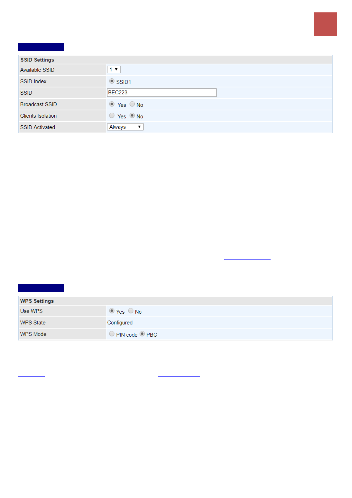
Device Configuration
Interface Setup – Wireless 2.4GHz & 5GHz
67
SSID Settings
Available SSID: User can determine how many virtual SSIDs to be used. Default is 1, maximum is 4.
SSID Index: Select the number of SSIDs you want to use; up to 4 SSIDs are available in the list.
SSID: The SSID is the unique name of a wireless access point (AP) to be distinguished from another.
For security propose, change the default wlan-ap to a unique ID name to the AP which is already
built-in to the router’s wireless interface. Make sure your wireless clients have exactly the SSID as the
device, in order to get connected to your network.
Broadcast SSID: Select Yes to make the SSID visible so a station can obtain the SSID through
passive scanning. Select No to hide the SSID in so a station cannot obtain the SSID through passive
scanning.
Client Isolation: (Known as AP Isolation) After enabling this feature, all Wi-Fi clients connect to the
same Access Point, in the same local wireless network, cannot interact with each another.
SSID Activated: Select the time period during which the SSID is active. Default is always which
means the SSID will be active all the time without time control. See Time Schedule to set the timeslot to
flexibly control when the SSID functions.
WPS Settings
WPS (Wi-Fi Protected Setup) feature is a standard protocol created by Wi-Fi Alliance. This feature
greatly simplifies the steps needed to create a Wi-Fi network for a residential or an office setting. WPS
supports 2 types of configuration methods which are commonly known among consumers: PIN
Method (Personal Information Number) & PBC Method (Push Button Configuration).
Use WPS: Enable this feature by choosing the ”YES” radio button.
WPS State: Display whether the WPS is configured or unconfigured.
WPS Mode: Select the mode which to start WPS, choose between PIN Code and PBC (Push Button).
Selecting Pin Code mode will require you to know the enrollee PIN code.
To future understand the two modes of configuration; please refer to the example of the Wi-Fi
Protected Setup.
BEC 6500 Series User Manual
Page 74
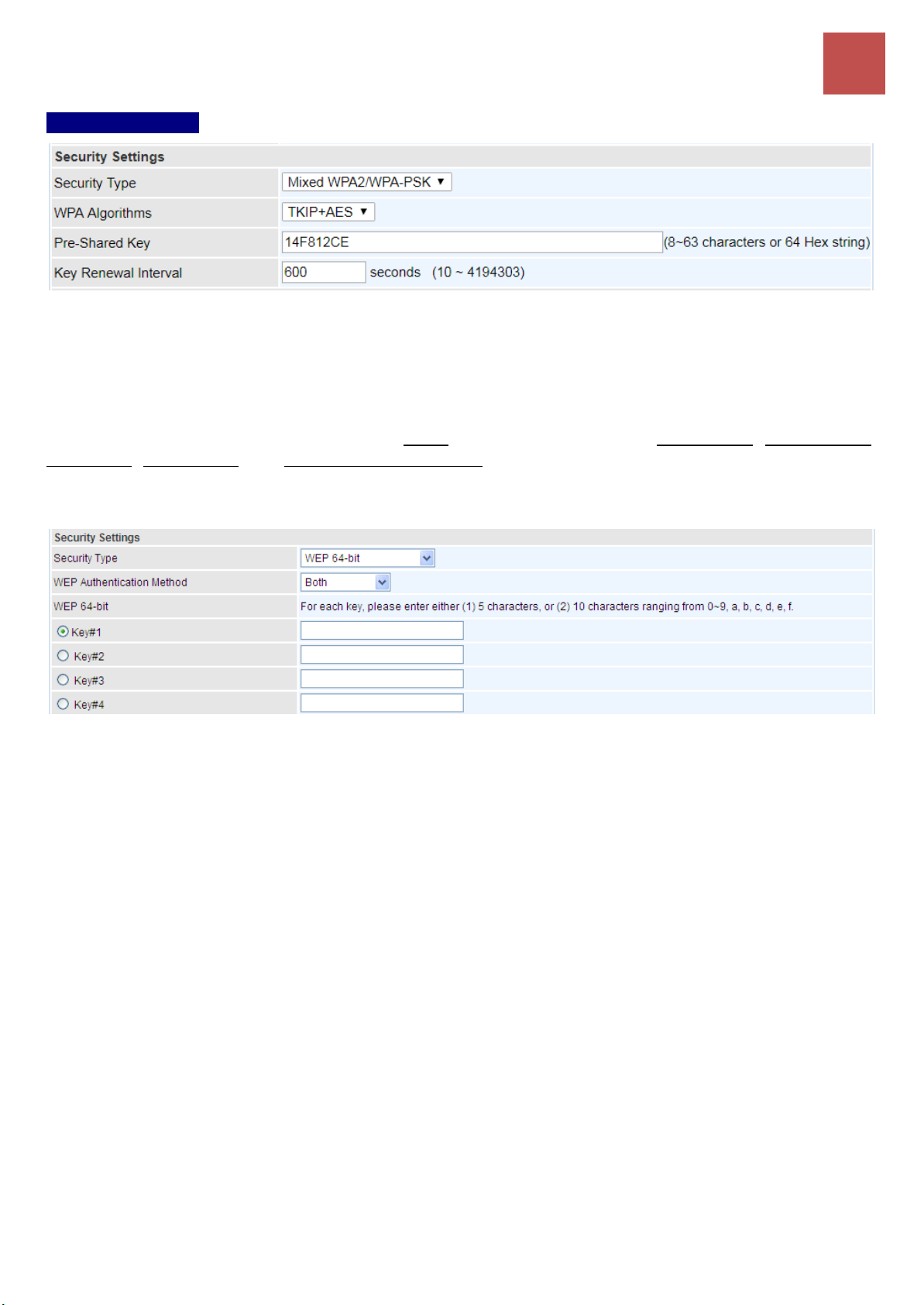
Device Configuration
Interface Setup – Wireless 2.4GHz & 5GHz
68
Security Settings
Security Type: You can disable or enable wireless security for protecting wireless network. The
default type of wireless security is OPEN and to allow all wireless stations to communicate with the
access points without any data encryption.
To prevent unauthorized wireless stations from accessing data transmitted over the network, the router
offers secure data encryption, known as WEP and WPA.
There are five alternatives to select from: Open (no security protected), WEP 64-bit, WEP 128-bit,
WPA-PSK, WPA2-PSK and Mixed WPA/WPA2-PSK. If you require high security for transmissions,
please select WPA-PSK, WPA2-PSK or WPA/WPA2-PSK.
Security Type - WEP
WEP Authentication Method: WEP authentication method, there are two methods of authentication
used, Open System authentication (OPENWEB) and Share Key authentication (SHAREDWEB). We
suggest you select OPENWEB.
Key 1 to Key 4: Enter the key to encrypt wireless data. To allow encrypted data transmission, the WEP
Encryption Key values on all wireless stations must be the same as the router. There are four keys for
your selection. The input format is in HEX style, 5 and 13 HEX codes are required for 64-bitWEP and
128-bitWEP respectively.
If you chose WEP 64-bit, then enter any 5 ASCII characters or 10 hexadecimal characters ("0-9",
"A-F").
If you chose WEP 128-bit, then enter 13 ASCII characters or 26 hexadecimal characters ("0-9", "A-F").
You must configure all four keys, but only one key can be activated at any one time. The default key is
key 1.
NOTE: When you enable WPS function, this WEP function will
be invalid. And if you select one of WEP-64Bits/ WEP-128Bits,
the following prompt box will appear to notice you.
BEC 6500 Series User Manual
Page 75
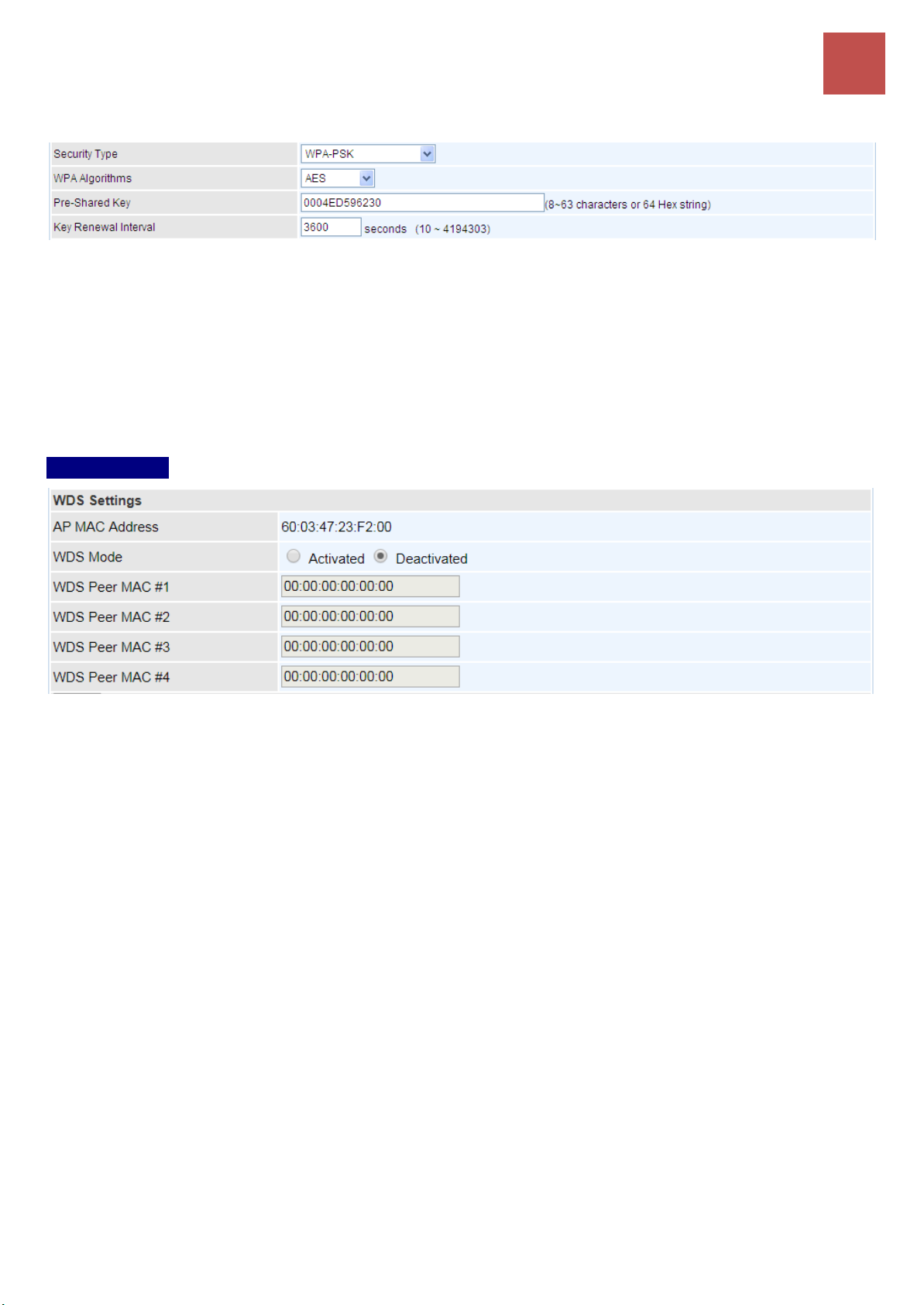
Device Configuration
Interface Setup – Wireless 2.4GHz & 5GHz
69
Security Type - WPA-PSK / WPA2-PSK / Mixed WPA & WPA2
WPA Algorithms: TKIP (Temporal Key Integrity Protocol) or AES (Advanced Encryption System)
utilizes a stronger encryption method and incorporates Message Integrity Code (MIC) to provide
protection against hackers.
Pre-Shared key: The key for network authentication. The input format should be 8-63 ASKII
characters or 64 hexadecimal characters
Key Renewal Interval: The time interval for changing the security key automatically between wireless
client and AP.
WDS Settings
WDS (Wireless distributed system) is a wireless access point mode that enables wireless link and
communication with other access point. It is easy to be installed, just define the peer’s MAC of the
connected AP.
WDS Mode: select Activated to enable WDS feature and Deactivated to disable this feature.
MAC Address: Enter the AP MAC addresses (in XX:XX:XX:XX:XX:XX format) of the peer connected
AP.
Click Save to apply settings.
BEC 6500 Series User Manual
Page 76

Device Configuration
Interface Setup – Wireless (Example on WPS using PIN)
70
Example: WPS using PIN Method (Personal Information Number)
PIN Method – Configure 6500 as a Registrar
1. Jot down the client’s Pin (e.g. 04640776) from the WPS utility (e.g. Ralink Utility)
2. Enter the Enrollee (Client) PIN code and then press Start WPS.
3. Go back to the wireless client’s WPS utility (e.g. Ralink Utility).
Set the Config Mode as Enrollee, press the WPS button on the top bar, select the AP (e.g. Billion_AP)
from the WPS AP List column. Then press the PIN button located on the middle left of the page to run
the scan.
BEC 6500 Series User Manual
Page 77

Device Configuration
Interface Setup – Wireless (Example on WPS using PIN)
71
4. The client’s SSID and security setting will now be configured to match the SSID and security setting
of the registrar, the BEC 6500.
BEC 6500 Series User Manual
Page 78

Device Configuration
Interface Setup – Wireless (Example on WPS using PIN)
72
PIN Method – Configure 6500 as an Enrollee
1. Jot down the AP PIN Code (e.g. 03454435) from the BEC 6500. Press Start WPS.
2. Launch the wireless client’s WPS utility (e.g. Ralink Utility). Set the Config Mode as Registrar. Enter
the PIN number in the PIN Code (e.g. 03454435) column then choose the correct AP (e.g. Billion_AP)
from the WPS AP List before pressing the PIN button to run the scan.
BEC 6500 Series User Manual
Page 79

Device Configuration
Interface Setup – Wireless (Example on WPS using PIN)
73
3. The router’s (AP’s) SSID and security setting will now be configured to match the SSID and security
setting of the registrar (client).
BEC 6500 Series User Manual
Page 80

Device Configuration
Interface Setup – Wireless (Example on WPS using PBC)
74
Example: WPS using PBC Method (Push Button Configuration)
1. Click the PBC radio button and click Save to apply the settings
2. Launch the wireless client’s WPS Utility (e.g. Ralink Utility). Set the Config Mode as Enrollee. Then
press the WPS button and choose the correct AP (e.g. Billion_AP) from the WPS AP List section
before pressing the PBC button to run the scan.
BEC 6500 Series User Manual
Page 81

Device Configuration
Interface Setup – Wireless (Example on WPS using PBC)
75
3. When the PBC button is pushed, a wireless communication will be established between your router
and the PC. The client’s SSID and security setting will now be configured to match the SSID and
security setting of the router.
BEC 6500 Series User Manual
Page 82
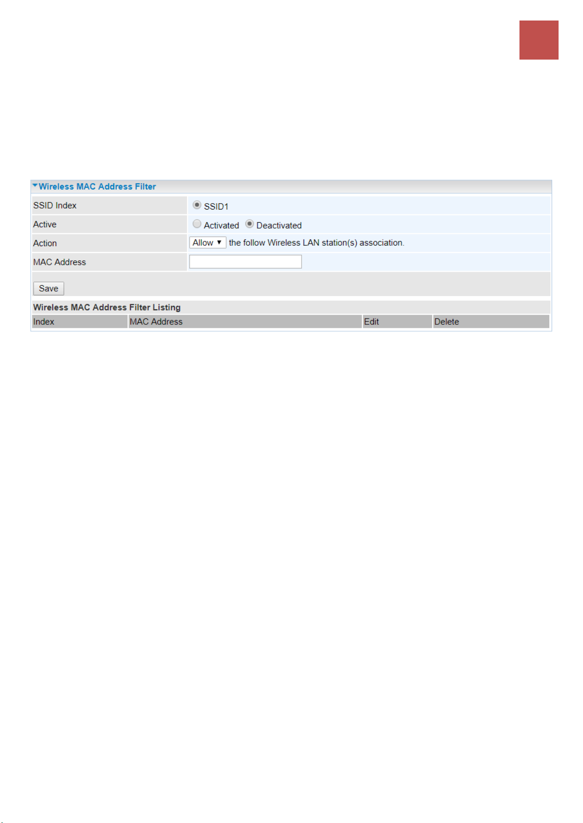
Device Configuration
Interface Setup – Wireless MAC Filter
76
Wireless MAC Filter
The MAC filter screen allows you to configure the router to give exclusive access to up to 8 devices
(Allow Association) or exclude up to 8 devices from accessing the router (Deny Association). Every
Ethernet device has a unique MAC (Media Access Control) address. The MAC address is assigned at
the factory and consists of six pairs of hexadecimal characters, for example, 00:AA:BB:00:00:02.
You need to know the MAC address of the devices you wish to filter.
SSID Index: Select the targeted SSID you want the MAC filter rules to apply to.
Active: Select Activated to enable MAC address filtering.
Action: Define the filter action for the list of MAC addresses in the MAC address filter table.
Select Deny to block access to the AP, MAC addresses not listed will be allowed to access the
router.
Select Allow to permit access to the router, MAC addresses not listed will be denied access to
the router.
MAC Address: Enter the MAC addresses (in XX:XX:XX:XX:XX:XX format) of the wireless station that
are allowed or denied access to the specified in these address fields.
Click Save to apply the settings.
BEC 6500 Series User Manual
Page 83
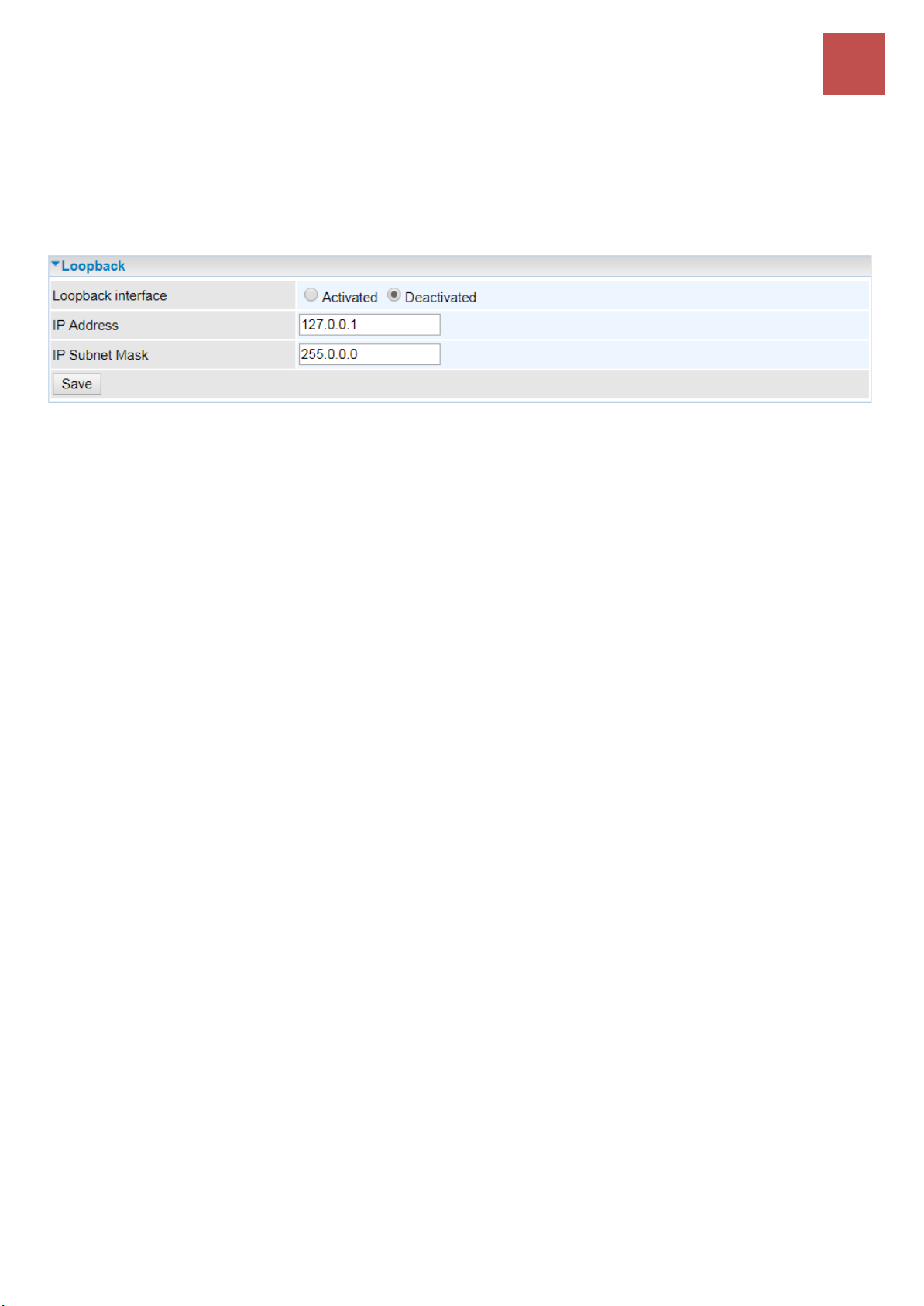
Device Configuration
Interface Setup – Loopback
77
Loopback
Loopback interface is a widely known virtual interface, not the physical interface, on router and is
highly robust and always up. The loopback interface has its own IP and subnet mask, often used for
router management as Telnet management IP and involved in BGP as BGP Update-Source and OSPF
as Router ID.
IP Address: Enter a dedicated IP address for the loopback interface.
IP Subnet Mask: Enter the subnet mask for the loopback interface.
Click Save to apply settings.
BEC 6500 Series User Manual
Page 84
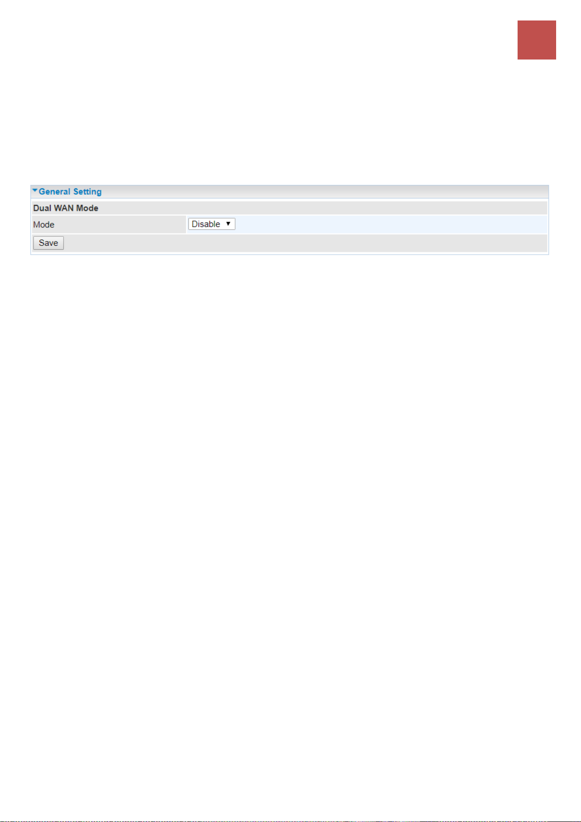
Device Configuration
Dual WAN – General Setting
78
Dual WAN
Dual WAN, is a feature to have two independent Internet connection connected concurrently, offers a
reliable Internet connectivity and maximize bandwidth utilization for critical applications delivery.
General Setting
Mode: Select a mode then click Save to proceed.
BEC 6500 Series User Manual
Page 85

Device Configuration
Dual WAN – General Setting (Failover & Failback)
79
❖ Failover & Failback
Auto failover/failback ensures always-online network connectivity. When primary WAN link (WAN1)
fails, all traffic will switch over to the backup WAN (WAN2) seamlessly.
Again, when the primary link is restored, traffic will be handled over from WAN2 to WAN1.
WAN Port Service Detection Policy
WAN1 (Primary): Choose a desired WAN as the primary WAN Link from the list.
WAN2 (Backup): Choose a desired WAN as the backup WAN Link from the list.
Keep Backup Interface Connected: Select the following option whether to keep the backup WAN
(WAN2) interface connected to the Internet.
Disable: Inactivate this feature.
Always: Keep the backup WAN (WAN2) interface always connected to the Internet
By Signal Strength: Enable and initiate automatic backup WAN to connect to the Internet at
all time until the RSRP / RSSI of primary WAN is greater than the Minimum RSRP / RSSI.
Minimum RSRP / RSSI: Set a minimum requirement for RSRP and RSSI for the primary WAN. Value
range from -111 ~ -5. 0 means don’t care/no need to check this value.
NOTE: Both the RSRP and RSSI cannot be 0 at the same time.
Connectivity Decision & Probe Cycle: Set a number of times and time in seconds to determine
when to switch to the backup link (WAN2) when primary link (WAN1) fails and vice versa.
Example, Auto failover takes place after straight 3 consecutive failures in every 30 seconds meaning
all traffic will hand over to backup link (WAN2) after primary link fails to response in total of 90 seconds,
30 seconds for 3 consecutive failures.
Note: Failover and Failback follow the same Connectivity Decision & Probe Cycle rule to failover from WAN1 to WAN2
or fallback from WAN2 to WAN1.
Failover/Fallback Rule Decisions:
1. Probe by Ping: Enable Ping to the gateway or an IP address
BEC 6500 Series User Manual
Page 86

Device Configuration
Dual WAN – General Setting (Failover & Failback)
80
Gateway: Internal system will wait for responses to the pings from the gateway of the WAN.
Host: Internal system will wait for responses to the pings from a fixed IP address.
2. Probe by Signal Strength: Enable to measure the LTE signal strength
Minimum RSRP / RSSI: Set a minimum requirement for RSRP and RSSI for initiating
automatic WAN failback or failover procedures.
The valid range is from -111 ~ -5. 0 means don’t care/no need to check this value.
NOTE: Both the RSRP and RSSI cannot be 0 at the same time.
Click Save to apply settings.
BEC 6500 Series User Manual
Page 87

Device Configuration
Dual WAN – General Setting (Load Balance)
81
❖ Load Balance
Load balance aggregates the bandwidth of the two WAN links to optimize traffic distribution.
When primary link, WAN1, goes down, all traffic will be redirected to the backup, WAN2, to ensure
service continuity.
WAN Port Service Detection Policy
WAN1 (Primary): Choose a desired WAN as the primary WAN Link from the list.
WAN2 (Backup): Choose a desired WAN as the backup WAN Link from the list.
Service Detection: Enable to detect WAN connectivity automatically.
Connectivity Decision: Set a number of times and time in seconds to determine when to turn-off the
Load Balancing service.
Example, Disable Load Balance after straight 3 consecutive failures in every 30 seconds meaning all
traffic will hand over to backup link (WAN2) after primary link fails to response in total of 90 seconds,
30 seconds for 3 consecutive failures.
Probe Ping on WAN 1 / WAN2: Enable Ping to the gateway or an IP address
Gateway: Internal system will wait for responses to the pings from the gateway of the WAN.
Host: Internal system will wait for responses to the pings from a fixed IP address.
Click Save to apply settings
BEC 6500 Series User Manual
Page 88

Device Configuration
Dual WAN – Outbound Load Balance
82
Outbound Load Balance
The connections are distributed over WAN1 and WAN2 so that it can utilize bandwidth of both WAN
ports. With Outbound load balance, traffic may be routed to a faster link when one of the WAN links is
slower or congested so that user gains better throughput and less delay.
User can distribute outbound traffic based on Session Mechanism or IP Hash Mechanism.
Base on Session Mechanism:
Balance by Session (Round Robin): Automatically assign requests/traffics to each WAN interface
based on real-time WAN traffic-handling capacity.
OR
Balance by Session weight: Manually Balance session traffic based on a weight ratio.
Example: Session weight by 3:1 meaning forward 3 requests to WAN1 and 1 request to WAN2.
Base on IP Hash Mechanism:
Balance by weight: Use an IP hash to balance traffic based on a ratio. It is to guarantee requests
from the same IP address get forward to the same WAN interface.
Click Save to apply settings
BEC 6500 Series User Manual
Page 89
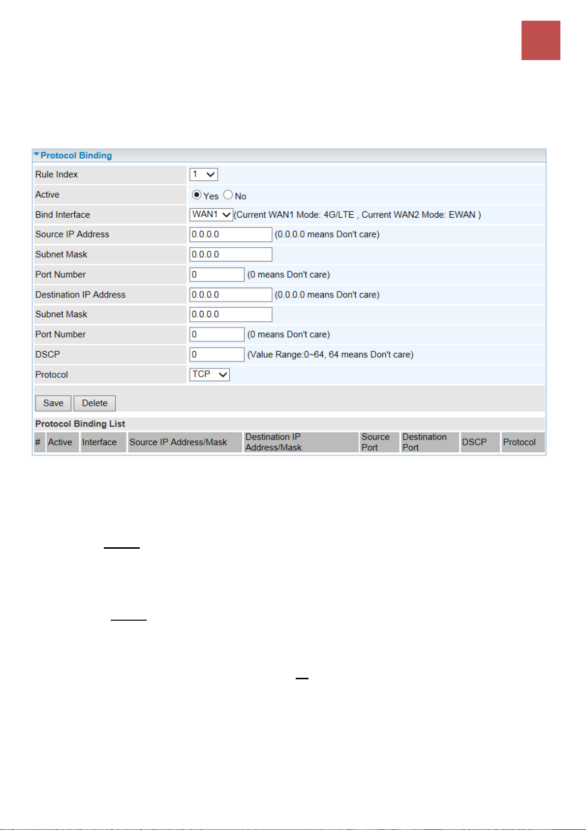
Device Configuration
Dual WAN – Protocol Binding
83
Protocol Binding
Protocol Binding lets you direct specific traffic to go out from a specific WAN port. Policies determine
how specific types of internet traffic are routed, for example, traffic from a specific IP address is
granted access to only one WAN port rather than using both of the WAN ports as with load balancing.
Rule Index: The numeric rule indicator. The maximum entry is up to 16.
Active: Click YES to activate the rule
Bind Interface: The dedicated WAN interface that guarantees to handle this traffic request.
Source IP Address: Enter the local network, known as source, IP address of the origin of a
traffic/packet. 0.0.0.0 means any IP address in the network.
Subnet Mask: Enter the subnet of the source network.
Port Number: Enter the port number which defines the application.
Destination IP Address: Enter the destination / remote WAN IP address where the traffic/packet is
going to. Enter 0.0.0.0 if no need to route to a specific IP address
Subnet Mask: Enter the subnet of the designation network.
Port Number: Enter the port number which defines the application.
DSCP: The DSCP value. Value Range from 0~64; 64 means any value/unspecified
Protocol: Select a protocol, TCP, UDP, ICMP, to use for this traffic.
Click Save to apply settings
Example:
All traffics from IP 192.168.1.100/255.255.255.0 with port 8080 will go through WAN1 interface.
The only time it would go through WAN2 interface is when WAN1 has no Internet connection.
BEC 6500 Series User Manual
Page 90
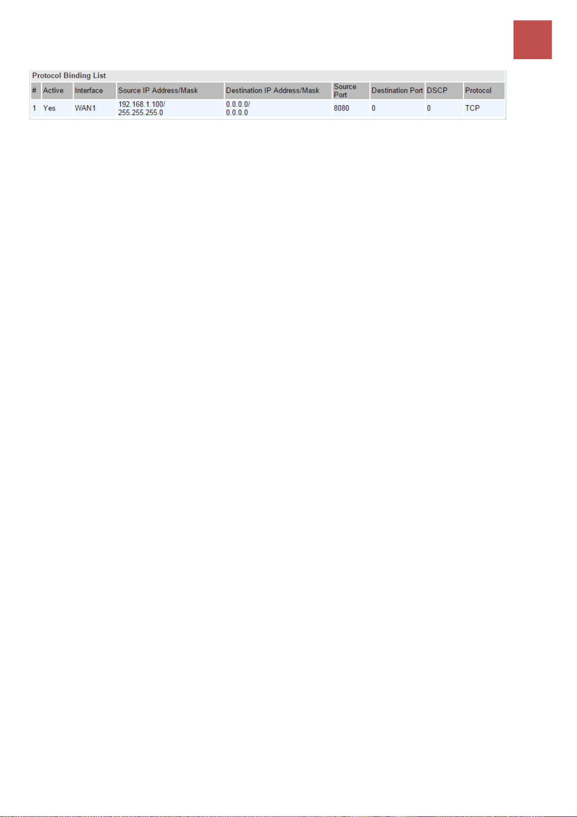
Device Configuration
Dual WAN – Protocol Binding
84
BEC 6500 Series User Manual
Page 91

Device Configuration
Hotspot – General Setting
85
Hotspot
The Wi-Fi hotspot offers Internet access for mobile devices like smart phones, laptops, or smart pad to
connect wirelessly in public locations such as in coffee shops, train station, airport, hotel, and much
more. A captive portal with a login page will prompt on the mobile devices and require all Wi-Fi clients
to accept the term of use before accessing to the Internet.
NOTE 1: Hotspot uses wireless network name, SSID1, to provide public Wi-Fi Internet access.
NOTE 2: To broadcast and see the hotspot ssid (SSID1), your BEC 6500 router must be connected to
the Internet first.
NOTE 3:It is ideal to change the Wi-Fi Hotspot (SSID) security type to OPEN (no encryption). Go to
Wireless >> Security Settings
General Setting
General Setting
Hotspot: Activate to enable the Wi-Fi hotspot feature.
Interface: Select Wi-Fi interface(s), exmaple: BEC0004 (SSID 1 of 2.4G) to handles the hotspot
traffic.
IP Address: The IP address for the Wi-Fi hotspot network.
Subnet Mask: Enter the subnet of the network.
Primary / Secondary DNS Server: Enter the IP addresses of the DNS servers. The DNS servers are
passed to the DHCP clients along with the IP address and the subnet mask.
Login Mode: Two (2) types of login modes to join the network.
Authentication: Username and Password (credential) is required to join the hotspot network.
Go down to the Authentication section below and select a method.
Agreement: No Username and Password is required. Automatically login to the hotspot
network after accept and agree to the terms (“Terms”) of use.
Redirect URL after Successful Login: Enter the URL (http:// is not required). After Wi-Fi client is
successful login to the network, the page will get redirected to this URL.
OR leave it blank to stay in current page.
NOTE: This new URL will be added to the Walled Garden automatically.
BEC 6500 Series User Manual
Page 92

Device Configuration
Hotspot – General Setting
86
Authentication
Authentication Methods: Two (2) network authentication methods, local built-in user account or a
remote, external RADIUS server. If the credential matches, the Wi-Fi client is granted access to the
network.
RADIUS (an external authentication server)
Primary RADIUS Server: The main IP address of the server.
Secondary RADIUS Server: The backup IP address of the server, if any.
Shared Secret Key: Enter the shared Secret given by the server
Built-in User Account (local database handled by the BEC 6500)
Go to the Built-in User Account to setup account usernames and passwords for the hotspot.
Authentication Protocol: Manually specify CHAP (Challenge Handshake Authentication Protocol) or
PAP (Password Authentication Protocol). When using PAP, the password is sent unencrypted, while
CHAP encrypts the password before sending, and also allows for challenges at different periods to
ensure that an intruder has not replaced the client.
Session Settings
Session Timeout (in seconds): The time period of a Wi-Fi client is allowed to access to the Internet.
After this timeout period, a new authentication is required.
Idle Timeout (in seconds): The allowed inactivity time of a Wi-Fi client. After this timeout period, a
new authentication is required.
Upload / Download Bandwidth (in Kbps): The maximum upload and download link speed, value
range from 0 ~ 5120Kbps; 0 means no speed limitation.
Maximum Upload / Download Data Usage (in MBytes): Pre-configure a maximum upload and
download data allowed for each session. value range from 0 ~ 5120MB; 0 means no speed limitation.
BEC 6500 Series User Manual
Page 93

Device Configuration
Hotspot – General Setting
87
Maximum Total Data Usage (in MBytes): Pre-configure total data usage allowed for each session.
value range from 0 ~ 5120MB; 0 means no speed limitation.
Captive Portal
UAM Server: Select a server you wish to use, Build-in, External or Socifi. Fill in the blanks to use
External UAM server.
Login URL: Enter the login URL offered by the UAM server.
Shared Secret: Set the shared secret password offered.
NAS ID: An assigned string for identification.
Location Name: An assigned string for identification.
Click Save to apply the settings
BEC 6500 Series User Manual
Page 94

Device Configuration
Hotspot – Built-in User Account
88
Built-in User Account
It is a local database on the router with pre-defined user accounts authorized by the BEC 6500 to grant
and provide Wi-Fi hotspot access for Wi-Fi capable devices/users.
16, maximum, accounts are allowed.
Rule Index: The numeric rule indicator. The maximum entry is up to 16.
Active: Select Yes to enable the rule of the account.
Username / Password: Create a user name and password for this user account.
Save: Click the Save button to apply the settings
Delete: Use the Rule Index to select an unwanted rule then click Delete button to remove it from the
Account list.
BEC 6500 Series User Manual
Page 95

Device Configuration
Hotspot – Authorized of Client
89
Authorized of Client
Add and predefine a trusted wireless MAC address of a Wi-Fi capable device for an immediate
hotspot/Internet access. Hotspot/Internet access requires no authentication.
16, maximum, accounts are allowed.
Authorized of Client: Select Activated to enable this feature.
Rule Index: The numeric rule indicator. The maximum entry is up to 16.
Active: Select Yes to enable the rule of the client.
MAC Address: Enter the wireless MAC address of the Wi-Fi device.
Save: Click the Save button to apply the settings
Delete: Use the Rule Index to select an unwanted rule then click Delete button to remove it from the
Client list.
BEC 6500 Series User Manual
Page 96
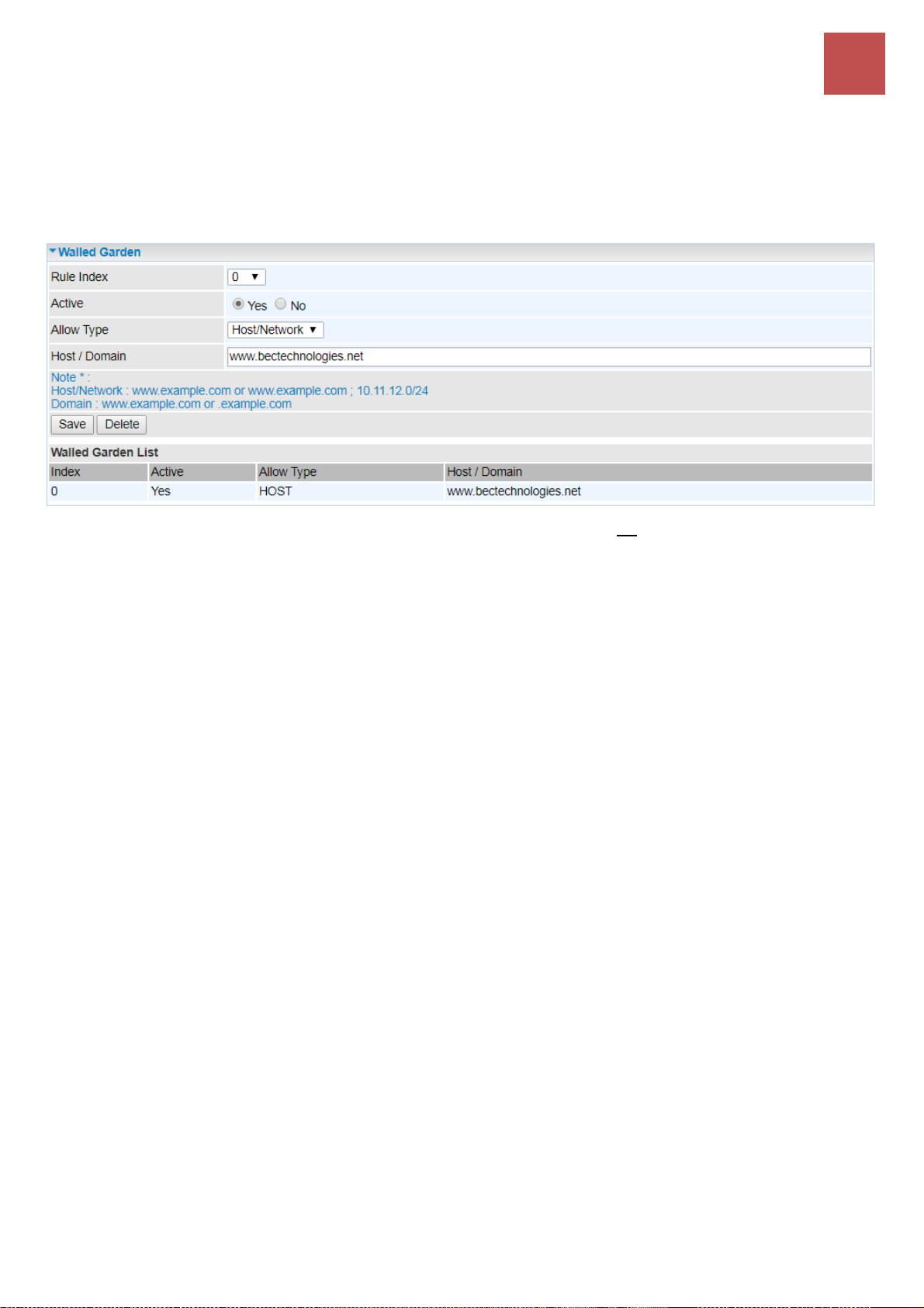
Device Configuration
Hotspot – Walled Garden
90
Walled Garden
Add and predefine websites (domain names) or web IP address to allow Wi-Fi devices / clients to
access to. Web site access requires no authentication.
16, maximum, websites / domains are allowed.
Rule Index: The numeric rule indicator. The maximum entry is up to 16.
Active: Select Yes to enable the rule of the walled garden.
Allow Type: Either a Host/Network or Domain.
Host / Domain name: Enter a valid domain, network, or website for unauthorized clients to access to.
Save: Click the Save button to apply the settings
Delete: Use the Rule Index to select an unwanted rule then click Delete button to remove it from the
Walled Garden list.
BEC 6500 Series User Manual
Page 97

Device Configuration
Hotspot – Advertisement
91
Advertisement
Add pop-ups ads and redirects to BEC 6500 Wi-Fi Hotspot, and only a random ad will be displayed per
a login.
16, maximum, ads are allowed.
Advertisement: Select Activated to enable this feature.
Mode: Two (2) web advertising methods are available.
Frame: Redirect to a random ad site, a full-page ad, before reaching to the login page. This
full-page ad will get redirect to the login page after 5-10 seconds.
Popups: A random pop-up ad display in a separate window after the login page.
Rule Index: The numeric rule indicator. The maximum entry is up to 16.
Active: Select Yes to enable the rule.
URL: Enter a valid
Save: Click the Save button to apply the settings
Delete: Use the Rule Index to select an unwanted rule then click Delete button to remove it from the
Walled Garden list.
BEC 6500 Series User Manual
Page 98

Device Configuration
Hotspot – Hotspot Status Log
92
Hotspot Status Log
Record all hotspot access information and e-mail the statistics report of the hotspot clients in a specific
duration.
Hotspot Status Log: Select Activated to enable this feature.
Log Data in every (minute): Input session log time duration, (min)1 to (max) 60 minutes.
Mail Session Log File in every (minute): BEC 6500 will send all access information, such as access
IP addresses, NAT tables, etc., to the administrator’s mail box in the specific time/minute.
NOTE: Please set up a dedicated or administrator e-mail account to receive Hotspot access information in the Mail Alert.
BEC 6500 Series User Manual
Page 99

Device Configuration
Hotspot – Customization
93
Customization: Select Activated to enable this
feature.
Title: The Banner message. Default is “Hotspot”
Login Subtitle: Default is “Welcome to my
Hotspot”
Term Part 1 / 2 / 3: Create your own Terms and
Conditions. To use default, same terms, please
skip this part.
NOTE: No newline is accepted in each text box.
Login Successfully Message: BEC 6500 will
send all access information, such as access IP
addresses, NAT tables, etc., to the
administrator’s mail box in the specific
time/minute.
Customization
Allow modification to some of the captive portal settings.
BEC 6500 Series User Manual
Page 100

Device Configuration
Hotspot – Customization
94
Login Successfully Message: A greeting
message after successful login to the Wi-Fi
hotspot. Default is “Success!”
Footnote: Additional information, if needed.
Default is “This service is provided for free and
used at your own risk.”
Show Logo: Select Activated to display
company Logo on the portal. (To change logo,
please contact with BEC technical support for
more infomraiton)
BEC 6500 Series User Manual
 Loading...