

Specifications are subjec t to changes without prior notice.
Measured in specific conditions
Please kee p for further u se
Designed f or color print ing
Other use o f the device i s outside the permit ted purpose and can not be
guarantee d by the manufac turer.
The manufacturer cannot be held responsible for incorrect installations or
inappropriate adjustments of the sensor.
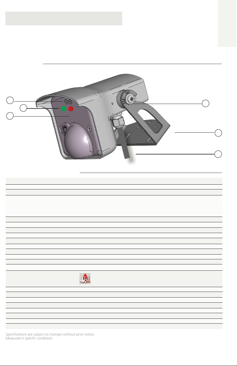
DESCRIPTION
1
2
3
TECHNICAL SPECIFICATIONS
Supply voltage:
Power consumption:
Mains frequency:
Output:
Max. contact voltage:
Max. contact current:
Max. switching power:
Output holdtime:
Mounting height:
Temperature range:
Humidity:
Degree of protection:
Dimensions:
Materials:
Weight:
Cable length:
Norm conformity:
12V to 24V AC ±10%; 12V to 24V DC +10% / -3%
< 3.5 W
50 to 60 Hz
2 relays (free of potential change-over contact)
42 V AC/DC
1 A (resistive)
30 W (DC) / 48 VA (AC)
0.5 s
8 ft - 16 ft
from -22 °F to + 140 °F
0 - 95% non condensing
IP65 / NEMA 4
5 in (L) x 4 in (H) x 3.8 in ( W)
ABS and polycarbonate
14 oz
32 ft / 105 m
Electromagnetic Compatibility (EMC) 2004/108/ EC, R&TTE: 1999/5/EC
IS40-P
ENGLISH
Presence sensor
for automatic industrial doors
1. push buttons
2. LED’s
3. infrared emitter
4. sensor angle indicator
5. bracket
6. cable
4
5
6
Technology:
Transmitter frequency/wavelength:
Transmitter power density:
Detection mode:
Detection field:
Min. detection speed:
Reaction time:
Tilt angle:
75.5696.07 IS4 0P 20170313 Page 1 of 8
active infrared (AIR)
875 nm
< 250 mW/m²
motion & presence
10 ft x 10 ft at max. mounting height of 16ft (emitting spots**)
0 in/s to activate detection
250 ms
15° - 45°
** zone detected by spotfinder, i.e. slightly larger than actual detection field

PRECAUTIONS
• This device IS NOT intended for use as a safety sensor.
• Not recommended for dynamic envioronments. (snow, rain, fog, etc.)
• Shut off all power before attempting any wiring procedures.
• Maintain a clean & safe environment.
• Constantly be aware of pedestrian/vehicle traffic around the area.
• Always stop pedestrian/vehicle traffic through the doorway when performing tests that may result in unexpected reactions
by the door.
• ESD electrostatic discharge: Circuit boards are vulnerable to damage by electrostatic discharge. Before handling any board
ensure you dissipate your body’s charge.
• Always check placement of all wiring before powering up to insure that moving parts will not catch any wires and cause
damage to equipment.
• Ensure compliance with all applicable safety standards upon completion of installation.
• DO NOT attempt any internal repair of the sensor. All repairs and/or component replacements must be performed by BEA Inc.
Unauthorized disassembly or repair:
1. May jeopardize personal safety and may expose one to the risk of electrical shock.
2. May adversely affect the safe and reliable performance of the product and will result in a voided product warranty.
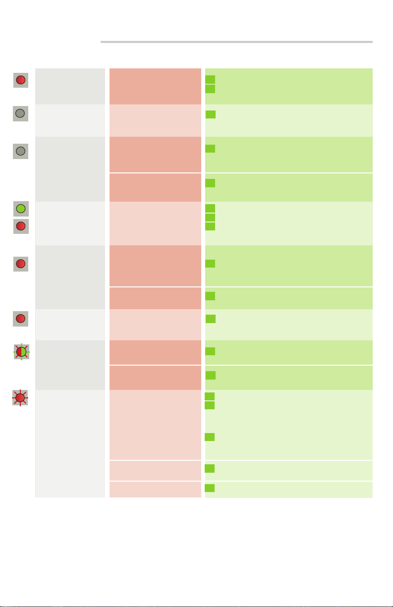
LED- SIGNAL
Activation/Pulse detection
LED flashes quickly
Presence detection
Setup
LED flashes
Parameter indication for manual setup
LED flashes
Value indication for manual setup
DIMENSIONS ( inches )
Wall mounting
Ceiling mounting
Bracket dimensions
SAFETY INSTRUCTIONS
Only trained and
qualified personnel
may install and setup
After installation,
save an access code
to lock the sensor.
Test the sensor for proper
performance before
leaving the premises.
the sensor.
The installer of the door system is responsible for carrying out a risk assessment and installing the sensor and the
door system in compliance with applicable national and international regulations and standards on door safety.
The warranty is void if
unauthorized repairs
are made or attempted
by unauthorized
personnel.
MOUNTING TIPS
Do not cover the
sensor.
Avoid extreme
vibrations.
Avoid proximity to neon
lamps or moving objects.
Avoid exposing the
sensor to sudden
temperature changes.
Page 2 of 8 75.5696.07 IS40P 20170313

HOW TO USE THE REMOTE CONTROL
After unlocking, the red LED
flashes and the sensor can be
adjusted by remote control.
ADJUSTING ONE OR MORE PARAMETERS
CHECKING A VALUE
RESTORING TO FACTORY VALUES
SAVING AN ACCESS CODE
The access code is recommended for sensors installed close to each other.
If the red LED flashes quickly after unlocking, enter an
access code from 1 to 4 digits.
If you do not know the access code, cut and restore
the power supply and within the first minute, you
can access the sensor without introducing any access
code.
x
The number of flashes
indicates the value of the
chosen parameter.
DELET ING AN ACCESS CODE
If you do not know the access code, cut and restore the power supply and, within the first minute, you can access
the sensor without introducing any access code. Additionally, within this minute an unknown access code may be
deleted via the remote following the steps outlined below. Press unlock, lock, 0, 0, 0, 0.
DELET ING AN UNKNOWN ACCESS CODE
75.5696.07 IS4 0P 20170313 Page 3 of 8
4
8
12
16
20
ft
ft
6
3 0
3
6
DOOR
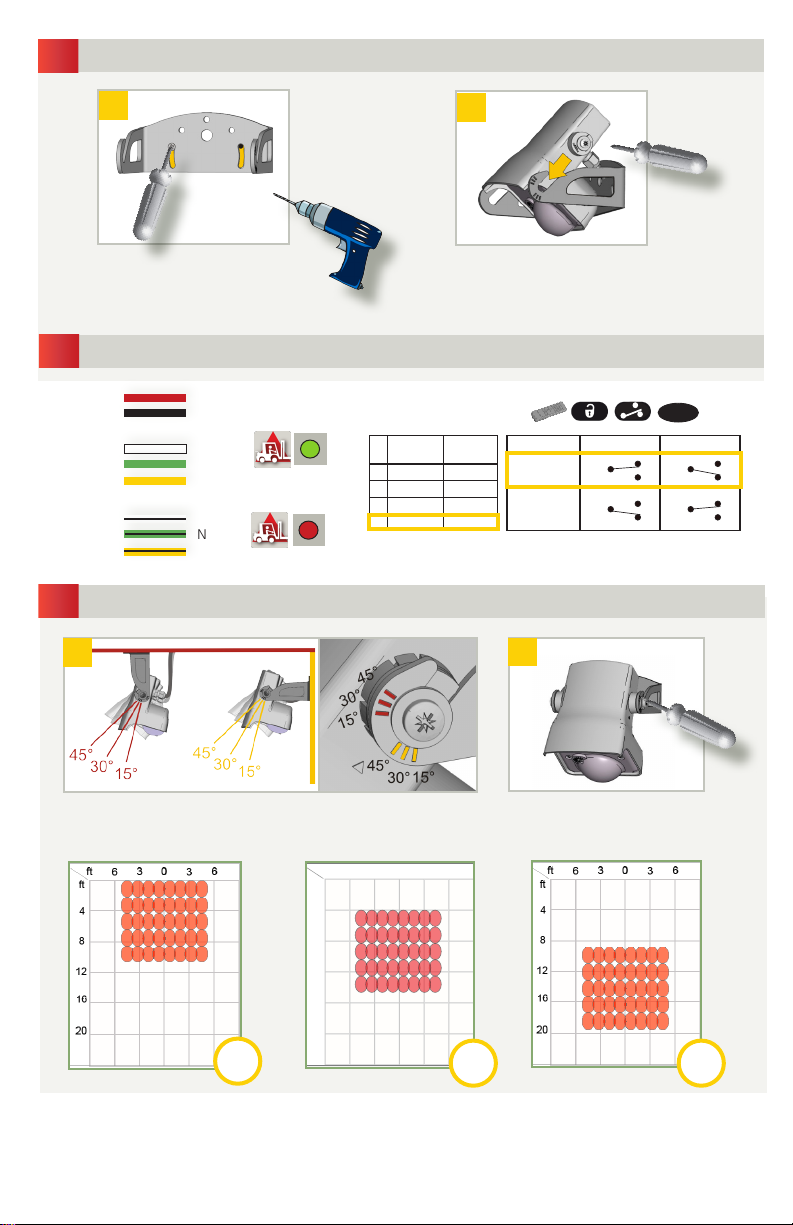
MOUNTING
1
1
Remove the bracket from the sensor.
Drill 2 holes accordingly. Mount the
bracket firmly. If necessary, drill an
additional hole to facilitate wire routing
WIRING
2
RED
BLACK
WHITE
GREEN
YELLOW
WHITE/BLACK
GREEN/BLACK
YELLOW/BLACK
SENSOR ANGLE
3
12-24 V
AC-DC
COM
NO
NC
COM
NO
NC
1
POWER SUPPLY
AIR OUTPUT 1
Presence or pulse signal
AIR OUTPUT 2
Presence signal
CEILING
2
Position the sensor on the
bracket and tighten the screws.
RELAY CONFIGURATION
Motion
Presence
Relay
1 Active Passive
2 Passive Active
3 Passive Passive
4 Active Active
Relay
1-4
Description Detection No Detection
Active
Relay
Passive
Relay
NO
COM COM
NC
NO
COM COM
NC
2
NO
NC
NO
NC
WALL
Adjust the angle of the sensor to position the detection fields.
DOOR
• The graphics above are not to scale and for illustration purposes and represent an approximate AIR detection field when mounted at
• It’s important to adjust the sensor angle to position the AIR field correctly for your application. Utilizing a mounting bracket, sensor
Page 4 of 8 75.5696.07 IS40P 20170313
15°
16 ft.Infrared field = emitting spots detectable by using the Spotfinder. The actual detection field is slightly smaller and influenced by
external factors.
location and reveal will dictate the sensor angle for your application.
DOOR
Tighten the screws firmly.
DOOR
30° 45°
AIR PATTERN SIZE AT 15O SENSOR ANGLE
Approximate default AIR pattern size using a 15º sensor tilt angle. The higher the mounting height the larger the AIR
pattern.
Width *
5 ft
7 ft
7. 5 f t
8.5 ft
10 f t
15-20 s 3 s
Depth *
5 ft
7 ft
7. 5 f t
8.5 ft
10 f t
* Dimensions are approximate.
4
Mounting Height
11. 5 f t
16 ft
SETUP
8 ft
10 f t
13 f t
(max)
Launch a setup to make a reference picture.
Step out of the detection field and do not leave any tools inside the detection field.
Upon power-up, the sensor launches a short setup.
IMPORTANT: Perform a functional test for proper operation before leaving the site.
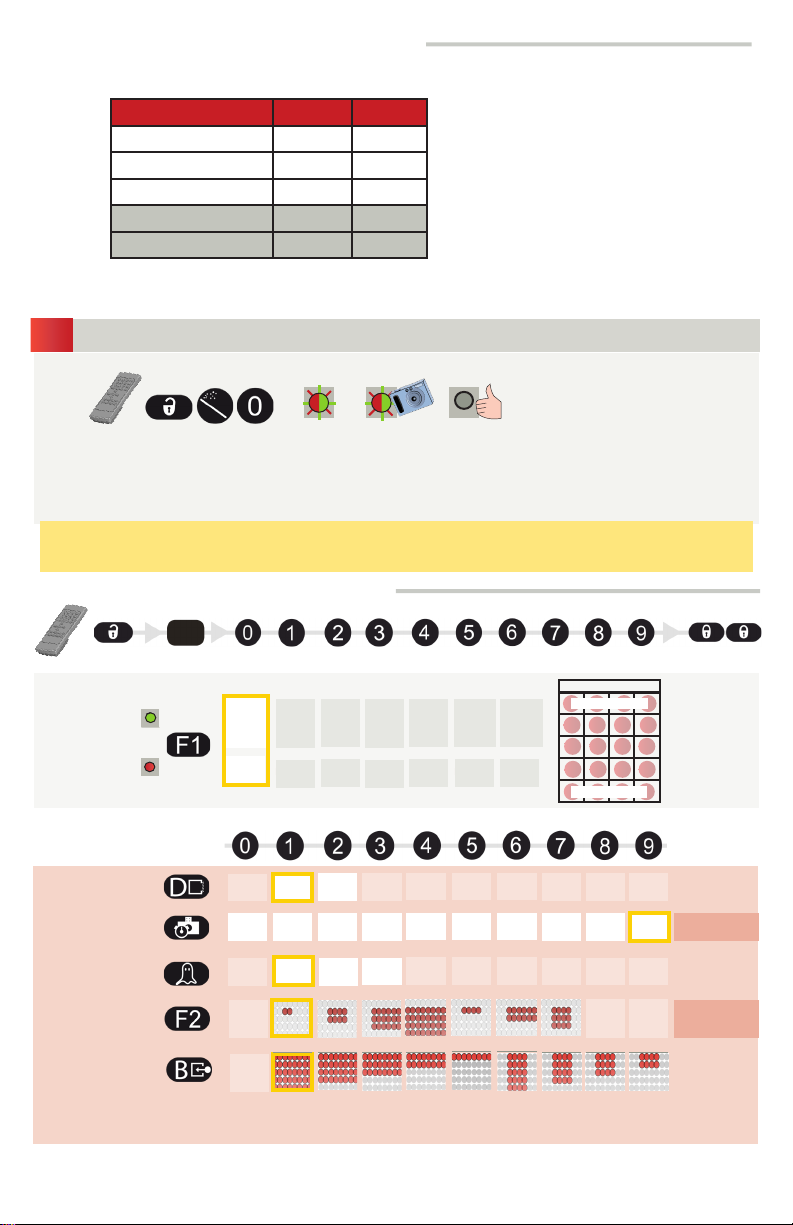
POSSIBLE REMOTE CONTROL SETTINGS
DOOR EXAMPLE
First Line
OUTPUT
REDIRECTION
RELAY 1
RELAY 2
motion
presence
signal
air entry
pulse
air exit
pulse
first or
last line
air entry
pulse
presencepresencepresence
presencepresencepresencepresence
first or
last line
air exit
pulse
presence
presence presence
presencepresence
presence
presence presence
Last Line
A
FREQUENCY
MAX. PRESENCE
DETECTION TIME
IR-CURTAIN
IMMUNITY
TARGET
SIZE
B
1 min 2 min30 s 10 min 20 min5 min 1 h 2 h1 h 30
low normal
high
*no
learn
* not
guaranteed
The position of the
target in the field is
random.
AIR-DETECTION
FIELD*
*AIR-DETECTION FIELD / TARGET SIZE CONTINUED ON NEXT PAGE
75.5696.07 IS4 0P 20170313 Page 5 of 8
DOOR
DOOR
DOOR
DOOR
2
3
7
5
6
2
5
6
1
1
2
3
4
7
5
6
1
2
3
4
7
5
6
1
DOOR
DOOR
DOOR
DOOR
DOOR
5
2
1
7
5
1
2
1
7
5
2
1
7
5
2
1
5
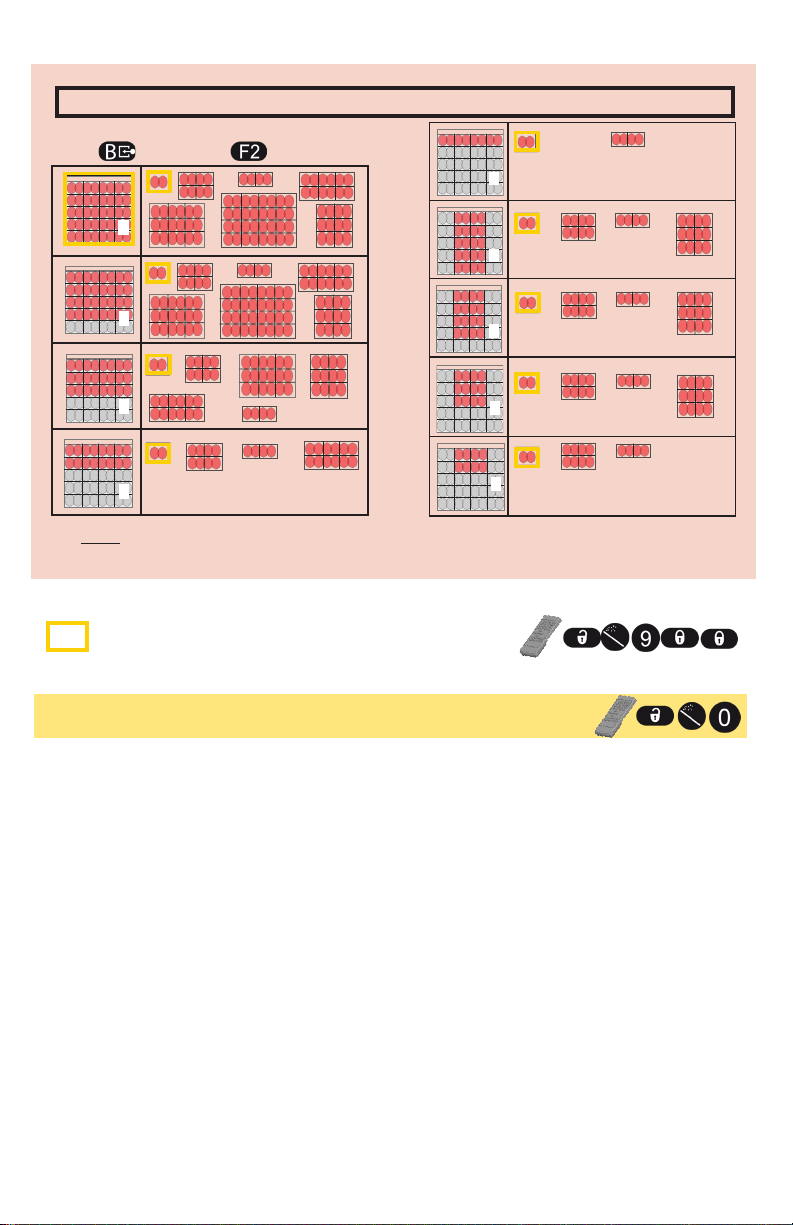
THE TARGET POSITION WITHIN THE "AIR" FIELD IS RANDOM
AIR PATTERN
SIZE
1
AVAILABLE TARGET SIZE
5
6
2
3
4
7
8
9
NOTE: TARGET SIZE MUST BE CAPABLE TO FIT INSIDE THE CHOSEN AIR PATTERN SIZE
FACTORY VALUES
IMPORTANT: Always finish an adjustment session by launching a setup
RESET TING TO FACTORY VALUES:
(see step 4)
and test the proper operation of the installation before leaving the premises.
Page 6 of 8 75.5696.07 IS40P 20170313
TROUBLESHOOTING
The door never closes
and the LED is ON.
The door remains
closed and the LED
is OFF.
The infrared sensor
does not react.
Object in the AIR detection
area.
The sensor power is off.
The infrared power emission
is too low according to the
mounting height.
Improper Target Size.
Move objects or reduce automatic learn time.
1
Wait for learn time to expire and/or Launch a
2
setup or cycle power
1
Check the wiring and the power supply.
1
Launch a new setup.
Step out of the detection field!
Ensure the target size is not to large
1
or larger than the pattern size.
The door opens
and closes
constantly.
Sporadic presence
detections for no
reason.
The red LED is
permanently ON
after a setup.
The setup lasts more
than 30 seconds.
The sensor does not
unlock and the red
LED flashes quickly.
The sensor does
not respond to the
remote control.
The sensor is disturbed
by the door motion or
vibrations caused by the
door motion.
The presence detection is
disturbed by rain or lamps.
The sensor is not installed
properly.
The sensor has failed the
AIR-setup.
The setup is disturbed.
Another sensor causes
interference.
The sensor needs an access
code to unlock.
The remote control
batteries are weak or
improperly installed.
The remote control is
poorly aimed.
The sensor is not powered.
Make sure the sensor is anchored properly.
1
Increase the sensor angle.
2
Reduce the AIR detection zone.
3
Set the AIR-curtain immunity to value 3.
1
Fasten the sensor firmly.
1
Launch a new setup and step out of the
1
detection field.
Make sure the detection field is clear and
1
launch a new setup.
Select a different frequency for each sensor.
1
Enter the right access code.
1
If you do not know the access code, refer to
2
page 3 and delete an unknown code.
Check the batteries and change them
1
if necessary.
Point the remote control towards the sensor.
1
Check the power supply of the sensor.
1
75.5696.07 IS4 0P 20170313 Page 7 of 8

©BEA | Original instructions | 75.5696
ACCESSORIES
10INDBRACKET
10BR3
10REMOTE
SINGLE LED
TRAFFIC LIGHT
10SPOTFINDER
DUAL LED
TRAFFFIC LIGHT
1024VAC
10MINIDBRACKET
COLUMN LIGHT
MODULAR
COLUMN LIGHT
Upon completion of the installation or service work, at a minimum, perform a safety inspection
for the type of Door/Gate per the manufacturer recommendations and/or per ANSI/DASMA guidelines
for best industry practices. Some examples but not limited to are ANSI/DASMA 102, ANSI/DASMA
107, UL 325. Make certain all appropriate industry warning labels are applied. It is the responsibility
of the installer/service personell to be familiar with national and local codes, standards, and regulatory
requirements. BEA Inc. recommends for installers and service personnel to be factory trained for the
type of door/gate system prior to performing installation or service.
BEA hereby declares that the MILAN is in conformity with the basic requirements and the
other relevant provisions of the directive 2004/108/EC.
Angleur, April 2011 Jean-Pierre Valkenberg, authorized representative
The complete declaration of conformity is available on our website: www.bea-industrial.be
Only for EC countries: According the European Guideline 2002/96/EC for Waste Electrical and Electronic Equipment (WEEE)
Tech Support: 1-800-407-4545 | Customer Service: 1-800-523-2462 | General Tech Questions: Tech_Services@beainc.com | Tech Docs: www.beasensors.com
Page 8 of 8 75.5696.07 IS40P 20170313
 Loading...