

Page 1
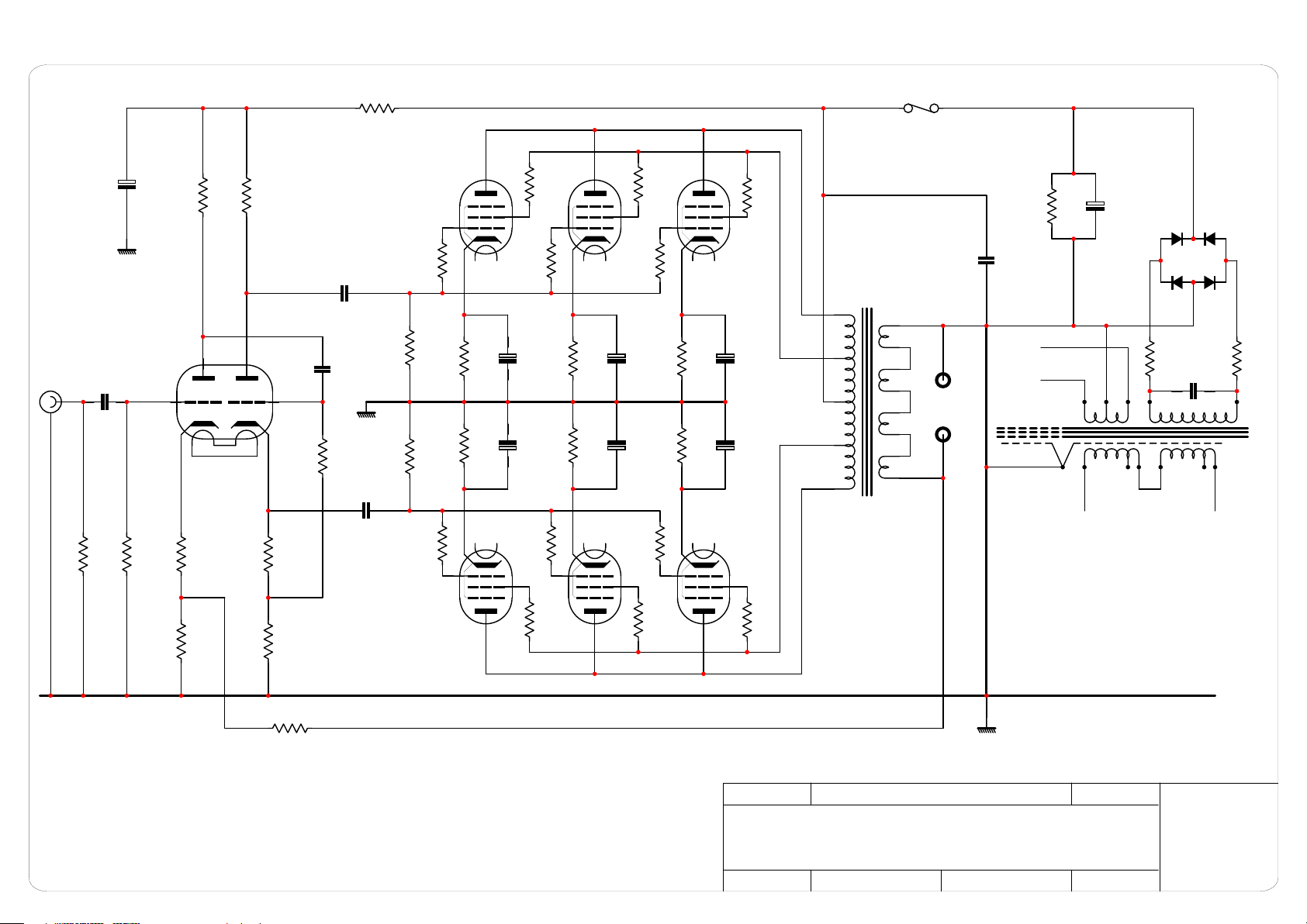
Input
eater
R1
68n
R2
680k
R31
300V
+
C15
220u
350V
R5
47k
200V
6
V1
R7
22k
200V
1
100n
630V
ECC81
2
3
49
100V
R8
680R
R9
22k
R6
1M
C1
220k
7
8
5
1.5V
R3
620R
R4
100R
C7
C4
100n
630V
C8
100n
630V
3W10k
R16
10k
V7
EL84
7
2
3
4 5
R30
100R
3W
9
R17
10k
V6
EL84
7
2
3
4 5
R29
100R
3W
9
R18
10k
V5
EL84
7
2
3
4 5
R28
100R
3W
9
F1
1A
Quick Blow
OPT-UL
TR2A
R12
470k
R11
470k
R13
10k
10V 10V 10V
+
C12
Tr4
Tr1
4 5
7
V2
220u
35V
C9
220u
+
35V
R14
10k
3
9
2
R25
100R
3W
270R
>1W
270R
>1W
10V 10V 10V
3
2
EL84
Tr5
270R
>1W
Tr2
270R
>1W
4 5
7
V3
EL84
+
C13
220u
35V
C10
220u
+
35V
R15
10k
9
R26
100R
3W
1
+
C14
Tr6
Tr3
4 5
7
V4
EL84
220u
35V
C11
220u
+
35V
9
R27
100R
3W
270R
>1W
270R
>1W
3
2
2
3
4
5
13
12
11
10
9
Output
8
7
6
340V
C17A
4.7u
630V
H
HT Secondary
same for other
Channel
R35
100k
+
C18
470uF
450V
3.15V
3.15V
Scrn
110 V
0V
D3
D1
D4
D2
R32
3R3
0V
120V
R33
3R3
C?
100n
110 V
0V
270V
120V
TR-Mains-P35
TR1
0V ref
R10
TBD
Notes
1) Resistors without power rating value are MRS25 0.6W
2) Derived from scrappy hand drawn schematic SOLD by Beard Audio which did not match actual build or have reference designators
3) LH Channel similar to RH with reference designators +100 except possitions R5 and R7 which may both be marked R107?
4) V101 LH Channel has the triode section pins swapped 123 = 678 and vice versa and V105-V106-V107 = V7-V6-V5
5) New output transformers were wound by UK manufacturer and enabled removal of C3 and C5 with better overall performance
6) Input stage beocmes a.c. coupled – R1 position is now a Capacitor and C1 a resistor for d.c. path of V1 - V101
7) Voltages shown in red are approximate and measured with high impedance meter – Some component changes marked in magenta
Revision:
1
Customer Service + Mod
Page Size:
Beard P35 Modified - RH channel
20 Sept 2012
Checked:Drawn: K. Snook
Page of
A4
1 1
 Loading...