

Page 1

www.bearcatpumps.com
623-587-1350
Curves:
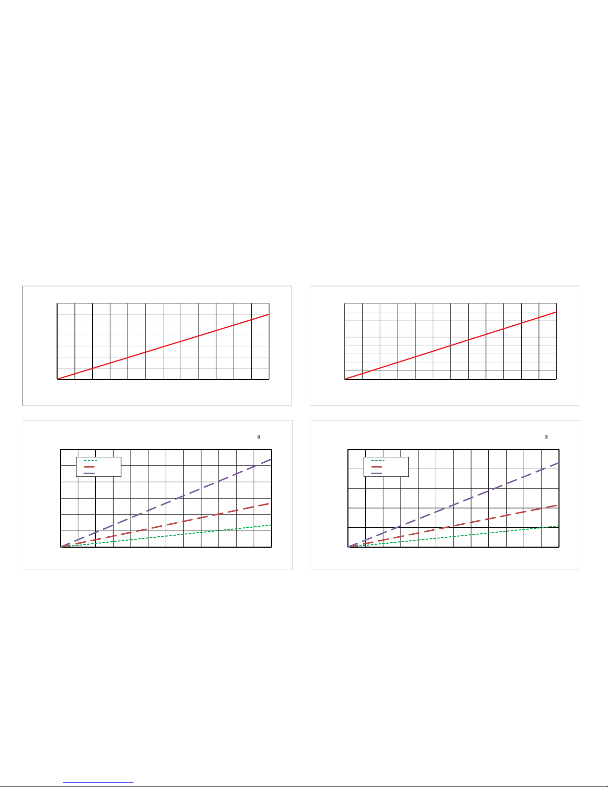
6-1 300 and 450 Curves
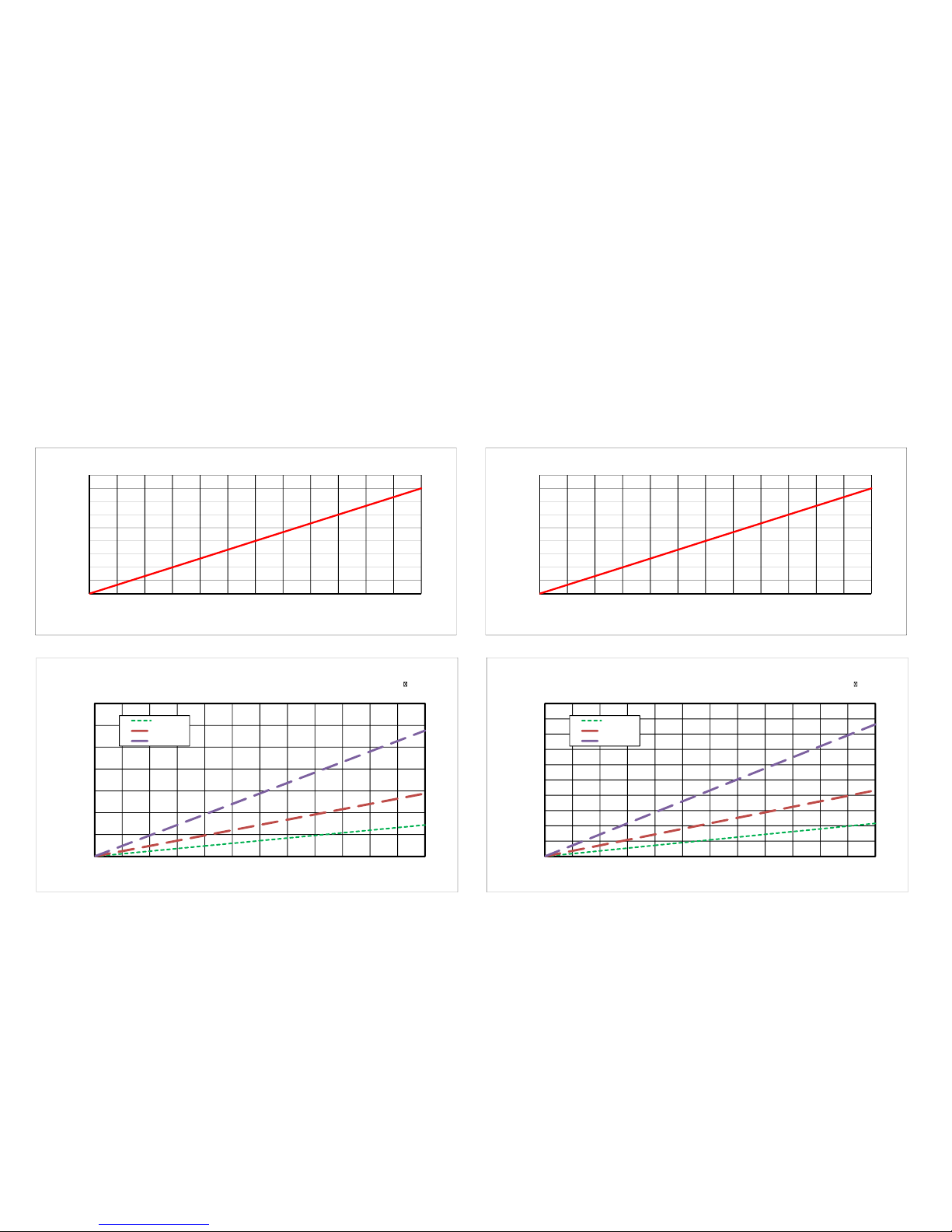
6-2 600 and 900 Curves
Example Systems & Misc:
7-1 Loading Skid
7-2 Metering with Coriolis Meter
7-3 Metering with Gear Meter
7-4 Truck Pumps
End Plate Diagrams:
4-1 C Style
4-2 B Style
4-3 V Style
4-4 T Style
4-5 N Style
4-6 W Style
4-7 R Style
4-8 U Style
Dimension Diagrams:
5-1 Models 300, 450 and 600
5-2 Model 900
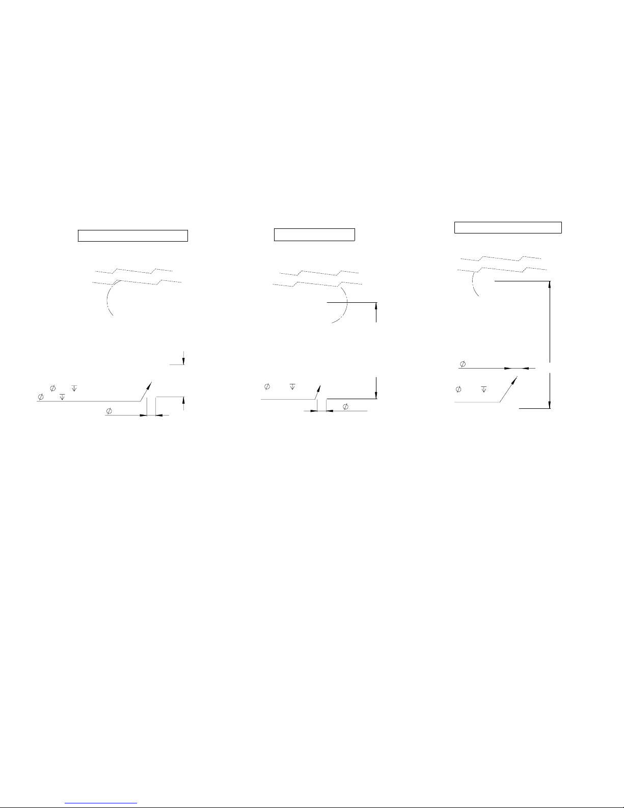
5-3 Shaft Dimensions (all models)
General Operation:
1-1 Safety Precautions
1-5 Liquid Lock Priming Diagram
1-2 Startup
1-3
Relief Valve
1-4
Flow Speed Control
Model Selection Guide:
2-1 Model Number (all pumps)
2-2 Choosing Style
2-3 Shaft and Seal type
2-4 Configuration and Options
Part Diagrams:
3-1 Base Components (all pumps)
3-2 Seals, Modified & Cooling
3-3 Seals, Modified (B) & Double Bearing
3-4 Seals, Packed
3-5 Shaft Styles
Index
BearCat Pumps
300,450,600 and 900
Pump and Gear Meter Manual
(Click links for quick access)
Page 2

This manual should be read entirely prior to the commencement of installation and operation.
•
Only qualified personnel should install, operate and maintain this pump and associated equipment.
•
Check pump for specific safety warnings/labels.
•
Prior to start-up, ensure complete cleanliness and integrity of the system in which the pump is installed.
•
In most cases the relief valve is factory set during performance test. In cases where the type of duty is not known
•
(such as distributors or stock orders) or where the components containing the relief valve come from pre-tested
stock batches, it is not possible to factory set the relief valve. In this case it is the installer’s responsibility to set the
relief valve in accordance with the specific application.
Pumps with heat tracing or jacketing necessary to prevent solidification of the product should be brought up to
•
working temperature prior to start-up.
All electrical work must be done in accordance with the manufacturers recommended procedures by qualified
•
personnel.
Ensure all guards are securely in place before operating the equipment. Do not remove guards at any time during
•
operation.
For pumps operating under ‘flooded’ suction, when venting the pump through a plug or valve, care should be
•
taken not to completely remove vent plugs or completely open any vent as this could result in liquid being
discharged from the openings under pressure.
Prior to start-up, ensure that the system valves and associated equipment are correctly set.
•
Wear appropriate safety atire including long sleeves, face shield, and gloves, whenever starting or operating the
•
pump.
www.bearcatpumps.com
623-587-1350
General Safety Precautions
1-1
Page 3

Rotation and Flow
Start-Up Procedure
Pump should turn freely by hand. Ensure all
1.
guards are in place.
Heat if necessary.
2.
Gradually open valves, and check for signs of
3.
leakage before starting pump.
If possible, add some of the liquid directly to the
4.
pump. This helps lubricate and prime during the
first start-up.
Check the rotation by flicking starter 'ON' then
5.
'OFF'. (Correct rotation shown in diagram)
Start pump slowly - check for leaks - gradually
6.
increase speed.
Re-Torque Bolts
Thermal expansion can loosen bolt connections. It is advised that all
bolt connections get checked and re-tightened after initial heat-up,
and during routine maintenance.
www.bearcatpumps.com
623-587-1350
Start-up Procedure
1-2
Page 4
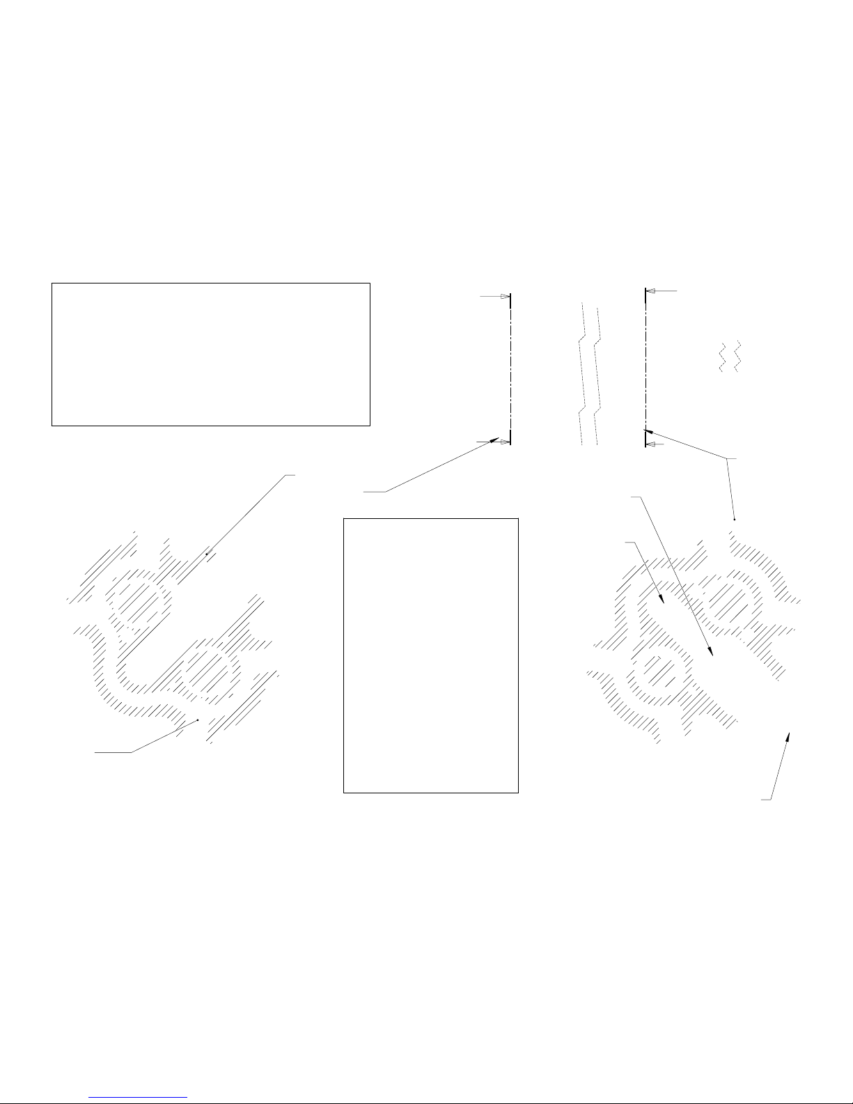
Heat Tracing
(Yellow)
Relief Valve
Poppet and
Spring
Adjuster Bolt
Flush (80 PSI @ 100GPM)
•
Backing off the bolt, each full
•
thread exposed subtracts
approximately 5PSI
Pressure By-Pass
(Red)
If the pump is turning as
shown view above, the
Front valve is controlling
pressure. The rear valve
can not open in this
condition, as the fluid
pressure is pushing
against it.
Rear Valve
Section
Front Valve
Section
Relief Valve Operation:
Each endplate can relieve pressure in one flow
direction only. As such, if the valves are set in
opposite directions, each can be adjusted to
independent pressures. It is possible to pressure
relieve at 80 PSI in one direction, while 30 PSI in
reverse.
www.bearcatpumps.com
623-587-1350
Relief Valve
1-3
Page 5

Flow Speed Control:
Pump speed control, either in the form of a Variable
Frequency Drive (VFD) or hydraulic control valve is a
valuable feature. Many factors can contribute to a
situation where pump speed would need to be
decreased for cautionary reason, or increased for
efficiency gains. These controls have other built in
features such as motor protection and pressure control.
They also provide valuable information when trouble
shooting. Without control, one is left with limited options
when problems occur. This can lead to damage,
shortened life, or compromised safety.
Energy Savings from a VFD
www.bearcatpumps.com
623-587-1350
Flow Speed Control
1-4
*Fixed Speed; Not everyone will choose some type of speed control. As a cautionary measure, we advise all fixed drive
systems start at a reduced speed. This should be as much as 50% below the pumps maximum. At initial start-up, this slower
speed is more forgiving When conditions are not as expected. Once the issues are corrected, the motor pulley can be
replaced with a larger pulley to increase speed as conditions allow.
The graph to the right shows the energy comparison of
Fixed Speed* with a VFD. Initially, fixed speed would
certainly be the least expensive. However, energy savings
should be considered during the cost analysis. At some
point this alone would cover the cost.
Page 6
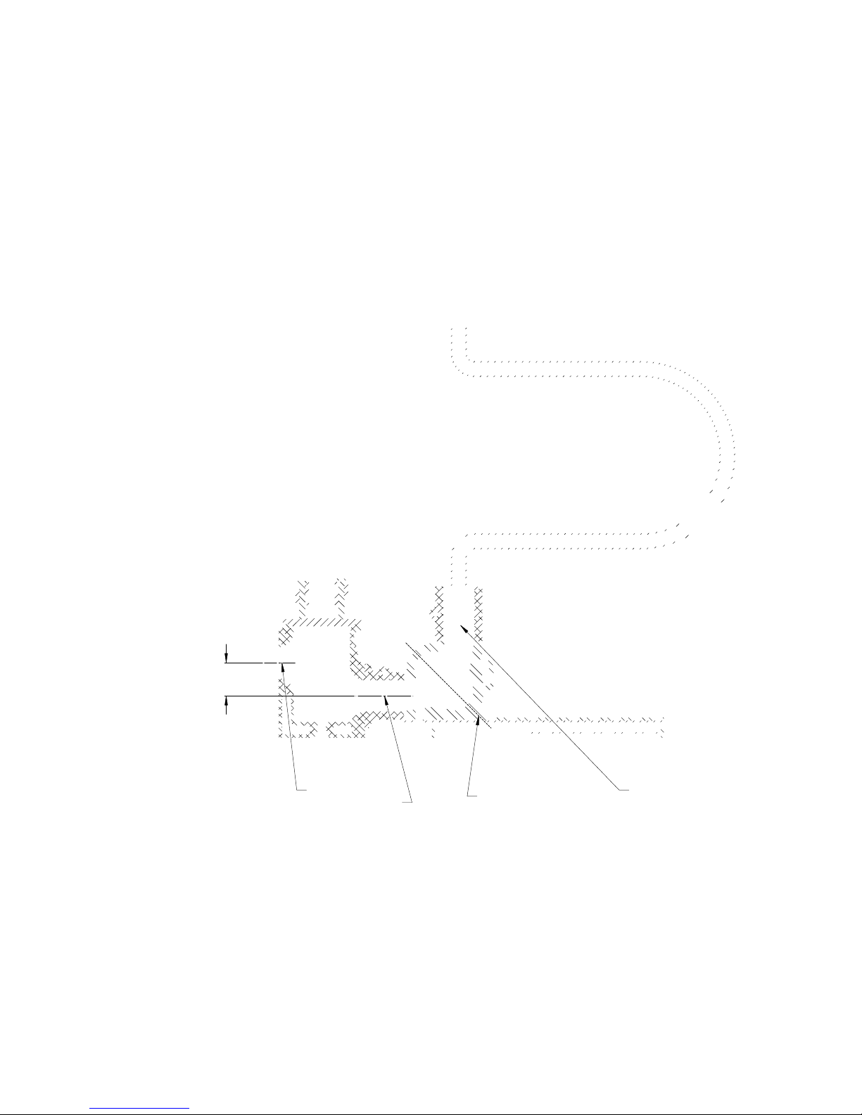
4.25
Pressure/Vacuum
Boundary Plane
Elevated Screen
Inlet to Pump Inlet
Verticle Discharge
Liquid Lock Priming System
This is a specific combination of three
key elements that significantly
improve the pumps ability to prime;
Elevated Screen Inlet to Pump Inlet
1.
Pressure/Vacuum Boundary Plane
2.
Verticle Discharge
3.
This condition allows the pump to
prime at a very slow speed and in a
continual state of lubrication.
www.bearcatpumps.com
623-587-1350
Liquid Lock Priming Diagram
1-5
Page 7
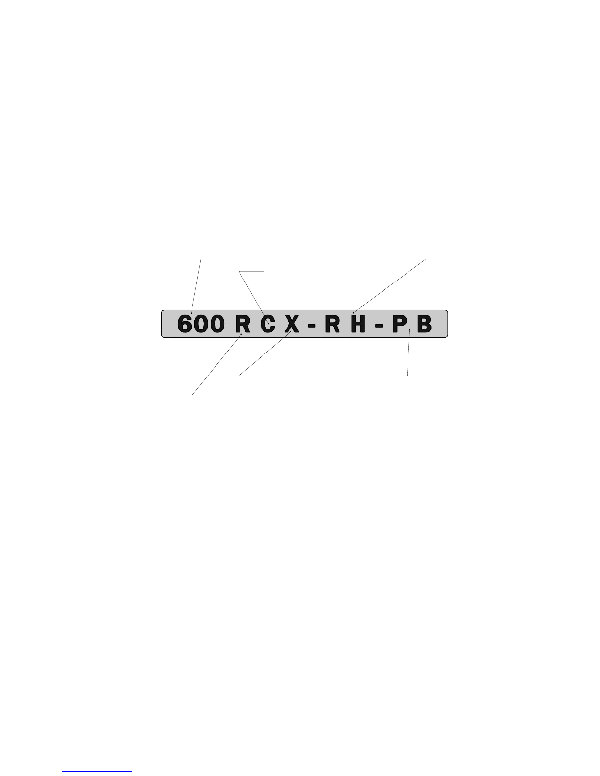
Example shown:
450VNX-RH-OB
Displacement
300 = 0.30 Gal/Rev
•
450 = 0.45 Gal/Rev
•
600 = 0.60 Gal/Rev
•
900 = 0.90 Gal/Rev
•
Pump or Meter Style
C = Bushed, No RV
•
B = Bushed, RV, Non Heated
•
V = Bushed, RV, Heated
•
T = Bushed, Heated Meter
•
- - - - - - - - - - - - - - - - - - - - - - - - N = Bearing, No RV
•
W = Bearing, No RV, No Heat
•
R = Bearing, RV, Heated
•
U = Bearing, Heated Meter
•
Shaft Seal
M = Modified Lip (standard)
•
N = Narrow Spacer (double)
•
C = Cooling Spacer (double)
•
B = Bearing Spacer (double)
•
P = Packed Seal (Non-Heated)
•
H = Heated Packed Seal
•
Drive Shaft Type
X = Extended
•
C = Cut to Custom Length
•
H = Hydraulic Mount Shaft
•
S = Short
•
Configuration
RH = Right High (standard)
•
RL = Right Low
•
LH = Left High
•
LL = Left Low
•
Option Items
OB = Outboard Bearing
•
PB = Pillow Block
•
EH = Electric Heat Cavities
•
EA = Encoder Guard and Coupler
•
www.bearcatpumps.com
623-587-1350
Building a Model Number
2-1
Page 8
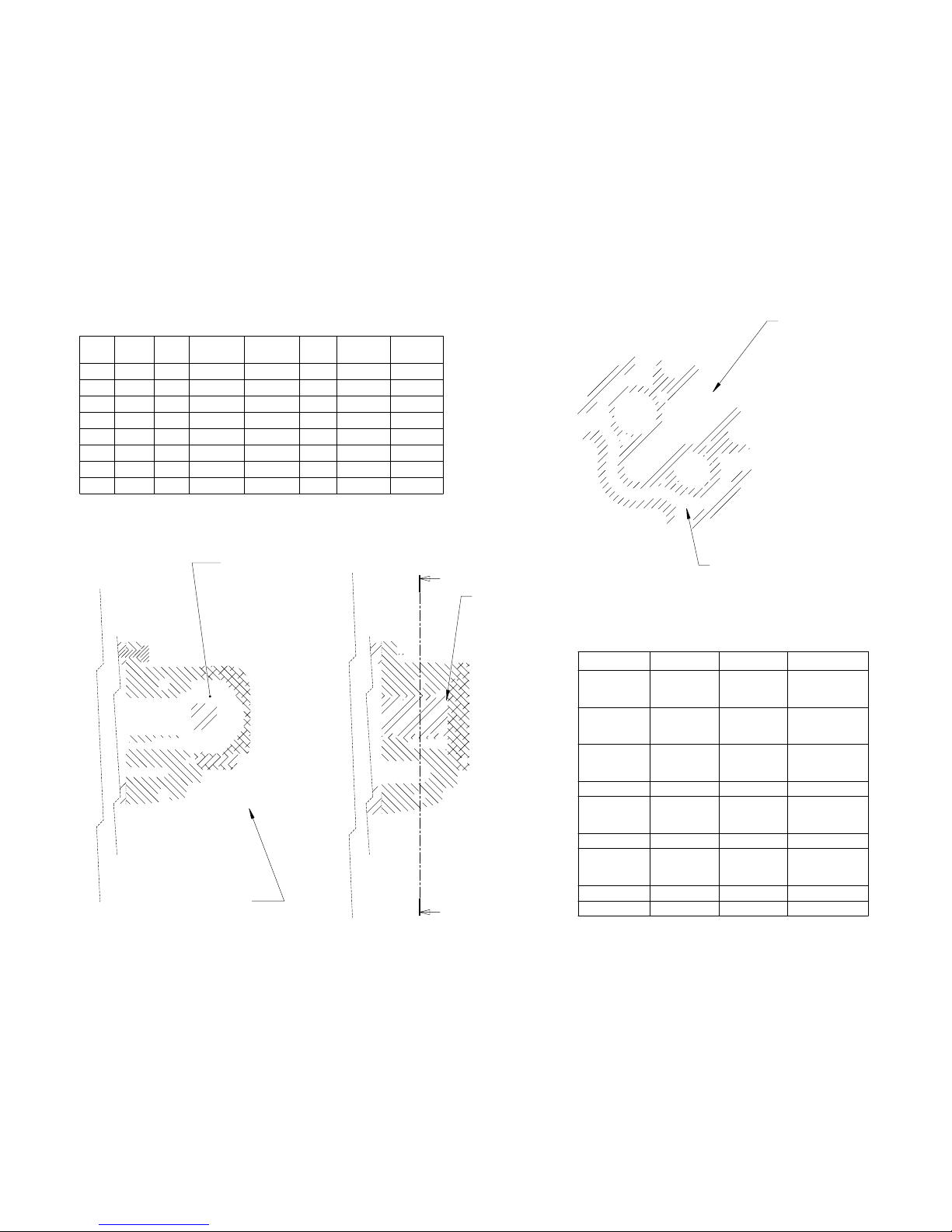
Bushing Style
C, V, B and T
•
Flat End Cap
•
Bearing Style
N, W, R and U
•
Domed End Cap
•
Grease Fittings
N, W, R and U
•
Domed End Cap
•
Grease Fittings
•
Relief Valve
V, B and R
•
Heat Tracing
V, T, R and U
•
Passage shown in yellow
•
Fittings included
•
Style
Relief
Heat
Bearing
Bushing Viton
Buna-N
Grease
C
X X
B
X X X
V
X X X X
T
X X X
N
X X X
W
X X X
R
X X X X X
U
X X X X
Material
Style
Seal Type
Notes
Rubberized
Asphalt
R U
C P
Use oversized
displacement
Modified
Asphalt
V T R U
M N C P
Emulsified
Asphalt
C V T
M N C
Crude Oil
B W
M D
Condensate
W
B
Use oversized
displacement
Dust Control
W
B
Abrasive
N W R U
C B
Use oversized
displacement
Corrosive
W
B
Hot
V T R U
C
www.bearcatpumps.com
623-587-1350
End Plate Style
2-2
Page 9
B: Bearing
Double
C: Cooling Double (shown)
N: Narrow Double
M: Modified
(standard)
P: Packed
4.5
H: Hydraulic Shaft.
Set distance from mount face. Used for
Hydraulic Motors and Gear Meters.
X: Extended shaft
S: Short shaft
Seal Type
www.bearcatpumps.com
623-587-1350
Shaft Type
2-3
Page 10
Shaft Low
Left Port
LL Example
Left Low
Configuration Examples
The configuration is determined by
side port postion and drive shaft
location. Looking down the drive
shaft, is the side port on the left or
right? Is the drive shaft in the high or
low position? See examples to left.
Right Port
Shaft High
RH Example
Right High
EA: Encoder Mount
Encoder coupler and guard
(encoder not included)
OB: Outboard Bearing
Option Items
PB: Pillow Block Bearing
www.bearcatpumps.com
623-587-1350
Configuration
2-4
Page 11

See
Endplate Diagrams
for details
Gears
(Use model number to identify)
Idler Shaft
(Use model number to identify)
Port Gasket
(Use model numder to indentify)
Housing
(Use model number to identify)
See
Seal Diagrams
for details
Drive Shaft
(Use model number to identify)
See
Option Items
for details
Pump Parts Diagrams
This shows a general pump diagram used with
the model number to identify parts.
Have the full model number when calling. If
you are unsure of your model number, have a
digital photo ready to email or text to our
technician to assist in identifying your pump.
Example Model Number: 450VMX-RH
www.bearcatpumps.com
623-587-1350
Base Component Diagram
3-1
Page 12
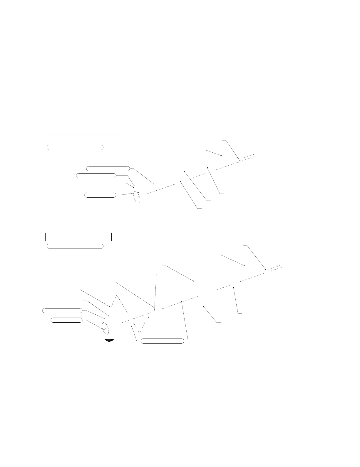
Modified Cap
1.5in Main Seal (x1)
Dust Seal Brkt (x1)
SHCS 0.25-20x0.5 (x3)
Dust Seal (x1)
MR24 Bearing
Modified Seal (standard)
.625 Plug Assembly (x1)
(install in pressure side only)
Cooling Double Seal
Grease Zerk (x2)
Bearing Cap Oring (x1)
1.5in Main Seal (x2)
V Modified Seal, Cap (x1)
SHCS 0.25-20x1.5 (x3)
Dust Seal (x1)
C Cooling Spacer (x1)
SHCS 0.375-16x0.75 (x5)
MR24 Bearing (x1)
Dust Seal Brkt (x1)
Relief Zerk (x1)
Grease Zerk (x1)
Bearing Cap Oring (x1)
.625 Plug Assembly (x1)
(install in pressure side only)
* Items included in seal kit
* Items included in seal kit
www.bearcatpumps.com
623-587-1350
Seal Diagrams
3-2
Recommended Grease: NLGI No. 2
Recommended Grease: NLGI No. 2
Page 13
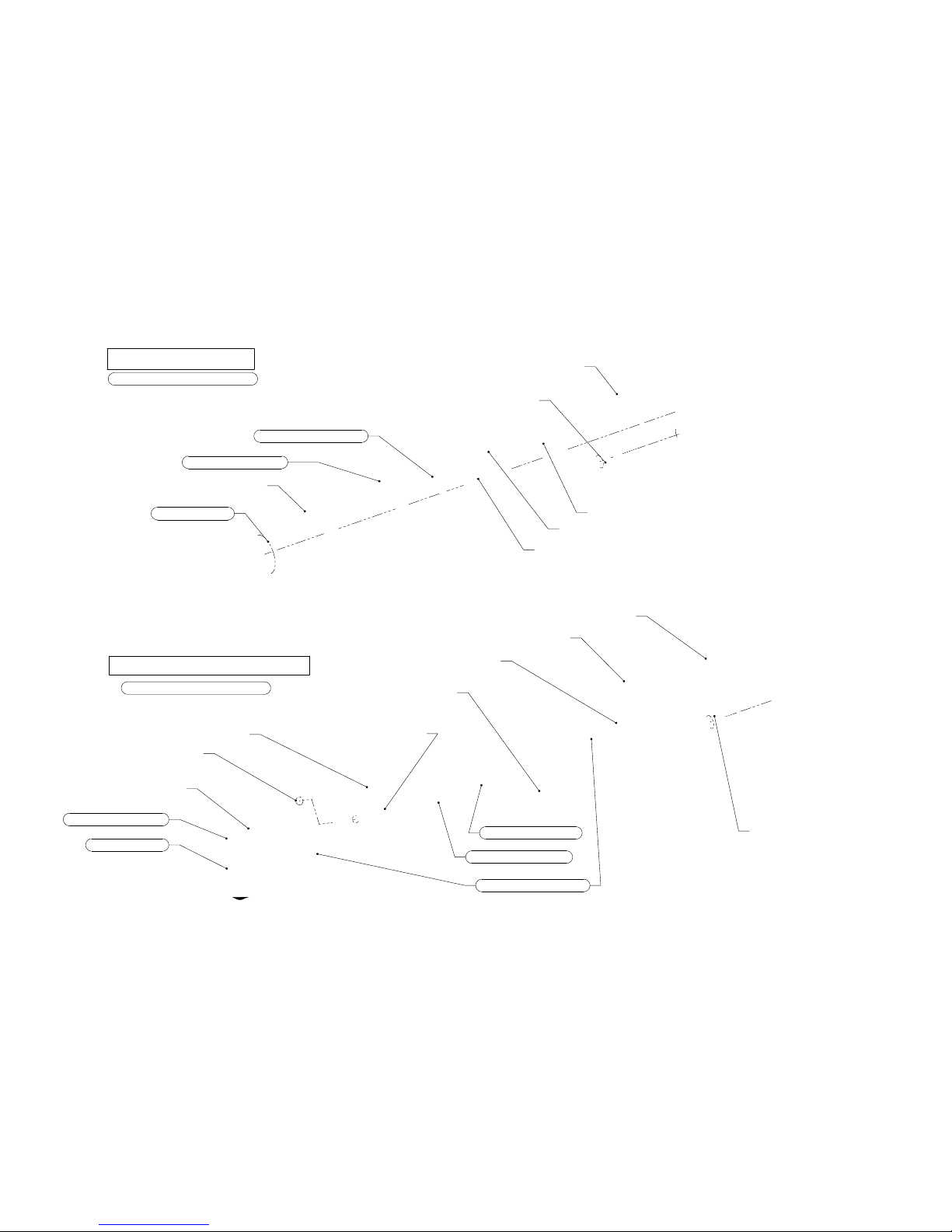
Modified Cap
1.5in Main Seal (x1)
Dust Seal Brkt (x1)
SHCS 0.25-20x0.5 (x3)
Dust Seal (x1)
MR24 Bearing
Modified (B) Seal
.625 B Plug Assembly (x2)
Double Bearing (B) Seal
Grease Zerk (x2)
Bearing Cap Oring (x1)
1.5in Main Seal (x2)
MR24 Bearing (x1)
SHCS 0.25-20x2.25 (x3)
Dust Seal (x1)
W Inner Split (x1)
B Double Seal Bearing, Cap (x1)
SHCS 0.375-16x0.75 (x5)
W Seal Oring (x1)
W Outer Split (x1)
Dust Seal Brkt (x1)
Relief Zerk (x1)
Grease Zerk (x1)
Bearing Cap Oring (x1)
.625 B Plug Assembly (x2)
* Items included in seal kit
* Items included in seal kit
www.bearcatpumps.com
623-587-1350
Seal Diagrams
3-3
Recommended Grease: NLGI No. 2
Recommended Grease: NLGI No. 2
Page 14

Modified Cap
1.5" Packing Washer (x1)
1/2-13 Nut and Washer (x2)
450 Gland (x2)
Packed Seal
Bearing Cap Oring Assembly (x1)
110_450 Stud (x2)
.625 Plug (x2)
450 Packing Ring Set (x1)
450 Gland Clip (x2)
SHCS 0.375-16x0.75 (x5)
* Items included in seal kit
www.bearcatpumps.com
623-587-1350
Seal Diagrams
3-4
Page 15
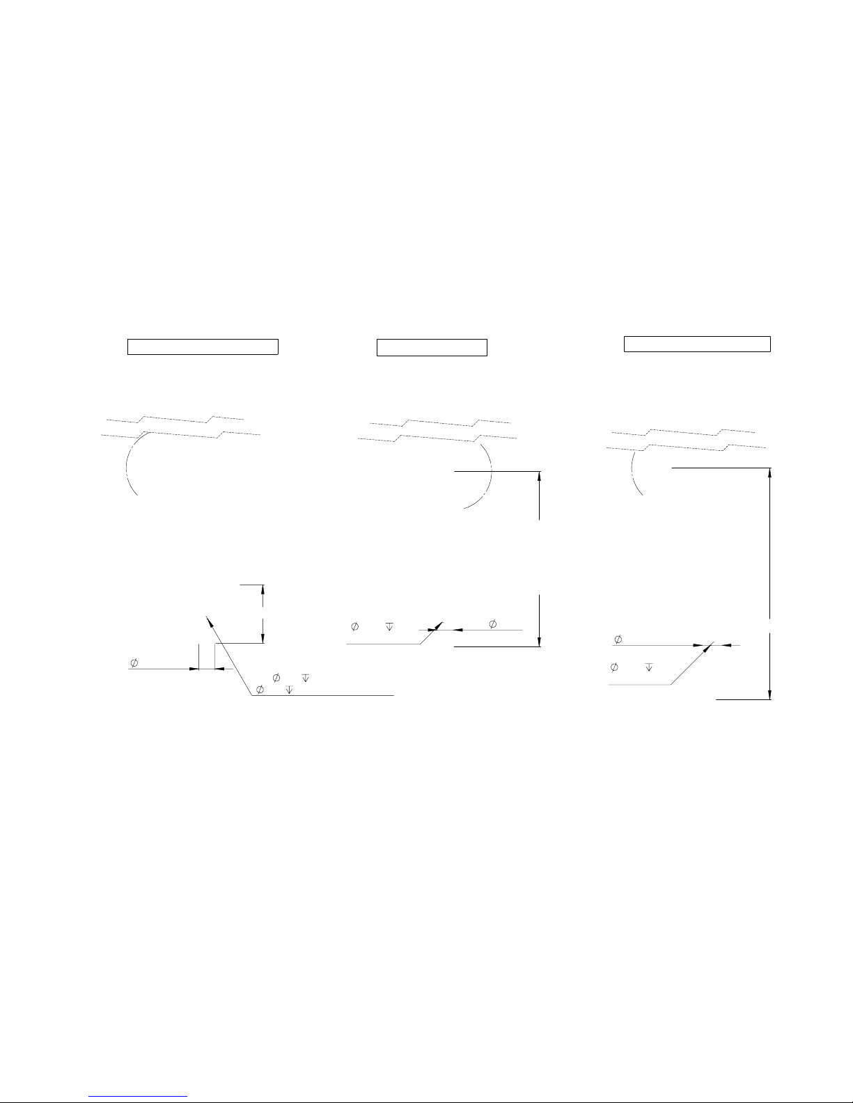
1.499
0.375
.19
KeyWay
18"
X
- Extended Shaft
11.10" (300)
13.60" (450/600)
0.250
0.13"
Keyway
1.249
(Available in B,C,
and V models only)
0.25
.13 (Standard)
0.31
.17 (B and W Models)
1.249
4.53
H -
Hydraulic Shaft
S
- Short Shaft
www.bearcatpumps.com
623-587-1350
Shaft Style Diagrams
3-5
Page 16
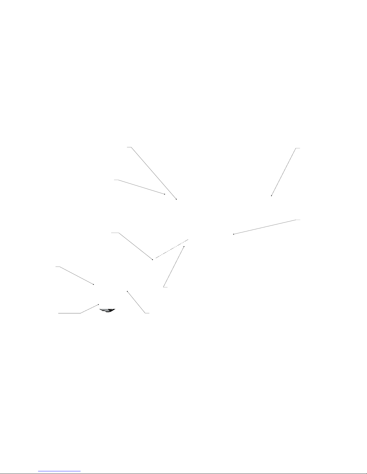
#12 Plug and Oring (x4)
Set Screw .375-16x.5 (x4)
(use on pressure side only,
vaccum side left open)
SHCS 0.375-16x0.75 (x20)
(20ft-lbs Torque)
End Cover Cap
(Blind Cap x3)
(Shaft Cap x1)
Long Bushing - Bronze
(Long x3, Short x1)
Bearing Cap Oring (x4)
End Plate Gasket
(qty varies)
HEX BOLT 0.5-13x1.5 (x16)
(45ft-lbs Torque)
C Style Endplate (x2)
www.bearcatpumps.com
623-587-1350
C Style Diagram
4-1
Page 17

#12 Plug and Oring (x4)
B Style Endplate (x2 Front - x2 Rear)
Set Screw .375-16x.5 (x3)
(use on pressure side only,
vaccum side left open)
SHCS 0.375-16x0.75 (x20)
(20ft-lbs Torque)
End Cover Cap
(Blind Cap x3)
(Shaft Cap x1)
RV Spring and Poppet Assy (x2)
Adjuster Plate Oring (x2)
Adjuster Nut Oring (x2)
Adjuster Nut (x2)
Long Bushing - Bronze
(Long x3, Short x1)
Bearing Cap Oring (x4)
SHCS 0.375-16x0.75 (x8)
(20ft-lbs Torque)
End Plate Gasket
(qty varies)
B Style Endplate (x2)
HEX BOLT 0.5-13x1.5 (x16)
(45ft-lbs Torque)
.625 B Plug Assembly(x2)
(see Seal Diagrams for additional Info)
www.bearcatpumps.com
623-587-1350
B Style Diagram
4-2
Page 18

#12 Plug and Oring (x6)
Set Screw .375-16x.5 (x4)
(use on pressure side only,
vaccum side left open)
Elbow #12and Oring (x2)
J Tube (x2)
SHCS 0.375-16x0.75 (x20)
(20ft-lbs Torque)
End Cover Cap
(Blind Cap x3)
(Shaft Cap x1)
RV Spring and Poppet Assy (x2)
Adjuster Plate Oring (x2)
Adjuster Nut Oring (x2)
Adjuster Nut (x2)
Long Bushing - Bronze
(Long x3, Short x1)
Bearing Cap Oring (x4)
SHCS 0.375-16x0.75 (x8)
(20ft-lbs Torque)
End Plate Gasket
(qty varies)
HEX BOLT 0.5-13x1.5 (x16)
(45ft-lbs Torque)
V, R or U Style Endplate (x2)
Str 12MJ-12MB Short and Oring (x4)
www.bearcatpumps.com
623-587-1350
V Style Diagram
4-3
Page 19
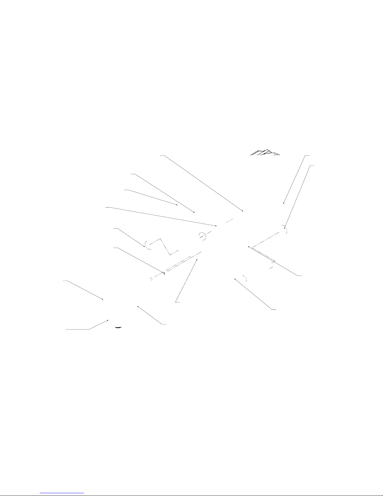
Str 12MJ-12MB Short and Oring (x4)
Set Screw .375-16x.5 (x8)
(Both holes plugged)
Str 12MJ-12MB Short
and Oring (x2)
J Tube, Meter (x2)
SHCS 0.375-16x0.75 (x20)
(20ft-lbs Torque)
End Cover Cap
(Blind Cap x3)
(Shaft Cap x1)
#12 Swivel Elbow (x2)
#12 Plug and Oring (x2)
Dura Steel Bushing (x4)
Bearing Cap Oring (x4)
Str 12MJ-12MB Long (x2)
End Plate Gasket
(qty varies)
HEX BOLT 0.5-13x1.5 (x16)
(45ft-lbs Torque)
T style Endplate (x2)
www.bearcatpumps.com
623-587-1350
T Style Diagram
4-4
Page 20
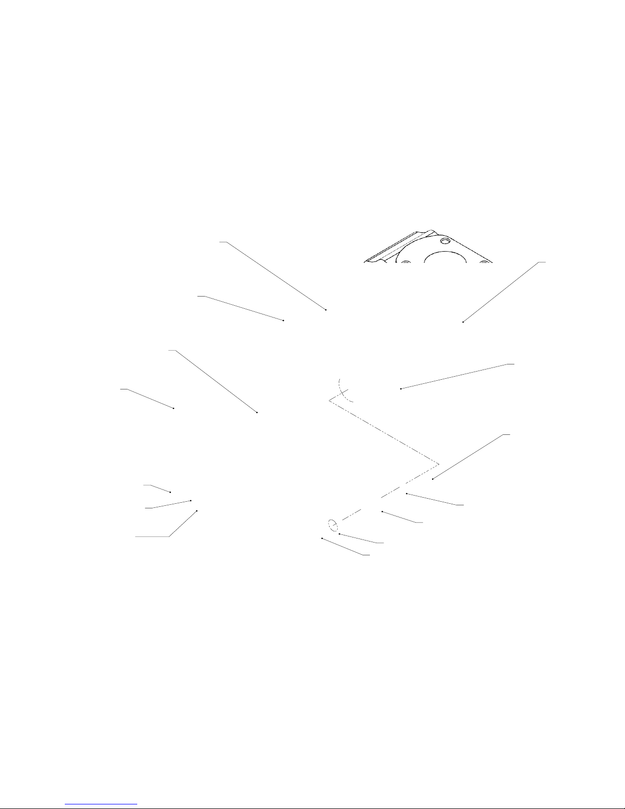
SHCS 0.375-16x1.5 (x20)
(20ft-lbs Torque)
HEX BOLT 0.375-16x1.25 (x4)
(20 ft-lbs Torque)
Grease Zerk (x4)
End Cover Cap
(Front and Rear)
Spherical Bearing (x4)
Belleville Washer (x2)
Castle Nut
and Cotter Pin (x2)
(100ft-lbs Torque)
End Plate Gasket
(qty varies)
HEX BOLT 0.5-13x1.5 (x16)
(45ft-lbs Torque)
N Style Endplate (x2)
N Style Piston (x4)
Bearing Cap Oring (x4)
960 Piston Bracket (x4)
#12 Plug and
Oring (x4)
www.bearcatpumps.com
623-587-1350
N Style Diagram
4-5
Page 21
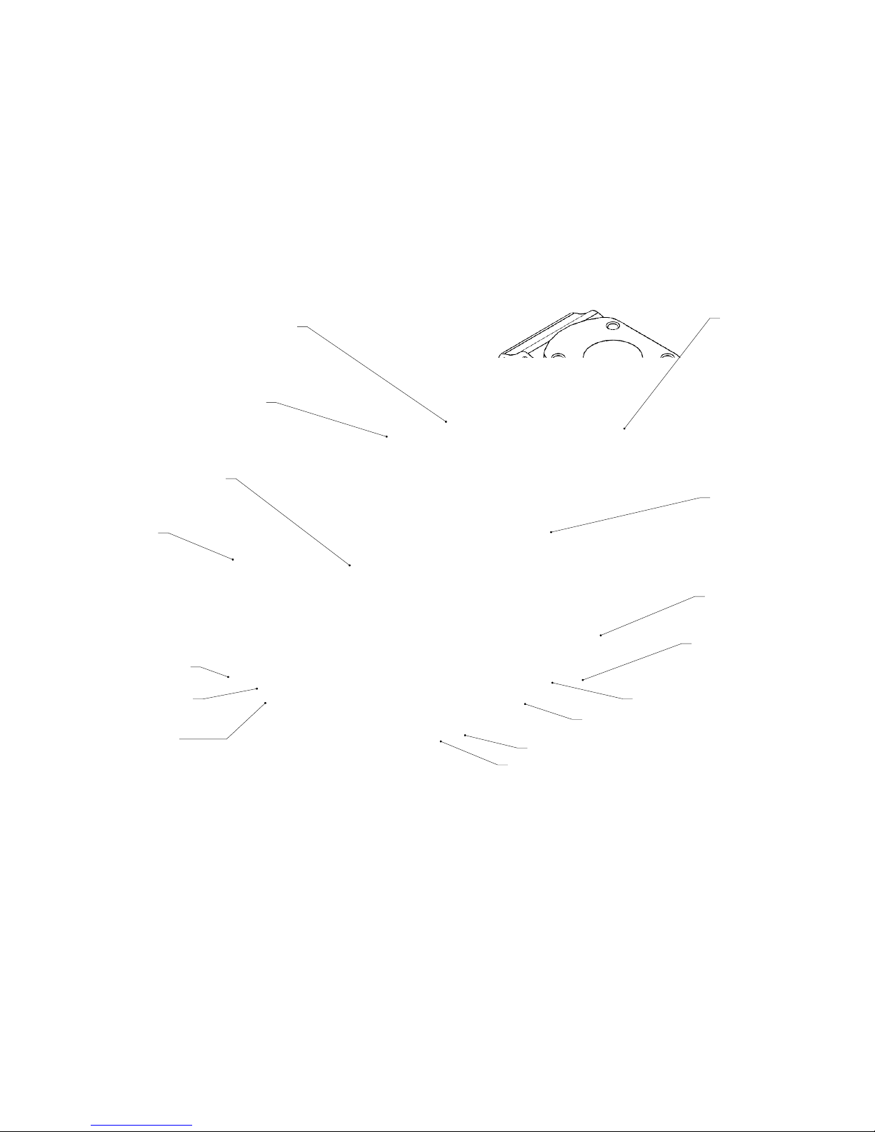
#12 Plugand Oring (x4)
SHCS 0.375-16x1.5 (x20)
(20ft-lbs Torque)
HEX BOLT 0.375-16x1.25 (x4)
(20 ft-lbs Torque)
Grease Zerk (x4)
End Cover Cap
(Front and Rear)
Spherical Bearing (x4)
Belleville Washer (x2)
Castle Nut
and Cotter Pin (x2)
(100ft-lbs Torque)
End Plate Gasket
(qty varies)
HEX BOLT 0.5-13x1.5 (x16)
(45ft-lbs Torque)
N Style Endplate (x2)
W_2 Face Oring (x4)
W Quad Oring (x4)
Bearing Cap Oring (x4)
W Sleeve (x4)
www.bearcatpumps.com
623-587-1350
W Style Diagram
4-6
Page 22

#12 Plug and Oring (x6)
Spacer Sleeve (x2 Front - x2 Rear)
Set Screw .375-16x.5 (x8)
Elbow #12and Oring (x2)
J Tube (x2)
SHCS 0.375-16x1.5 (x20)
(20ft-lbs Torque)
HEX BOLT 0.375-16x1.25 (x4)
(20 ft-lbs Torque)
Grease Zerk (x4)
End Cover Cap
(Front and Rear)
RV Spring and Poppet Assy (x2)
Adjuster Plate Oring (x2)
Adjuster Nut Oring (x2)
Adjuster Nut (x2)
Spherical Bearing (x4)
Belleville Washer (x2)
Castle Nut
and Cotter Pin (x2)
(100ft-lbs Torque)
Bearing Cap Oring (x4)
SHCS 0.375-16x0.75 (x8)
(20ft-lbs Torque)
End Plate Gasket
(qty varies)
HEX BOLT 0.5-13x1.5 (x16)
(45ft-lbs Torque)
V, R or U Style Endplate (x2)
Str 12MJ-12MB Short and Oring (x4)
www.bearcatpumps.com
623-587-1350
R Style Diagram
4-7
Page 23
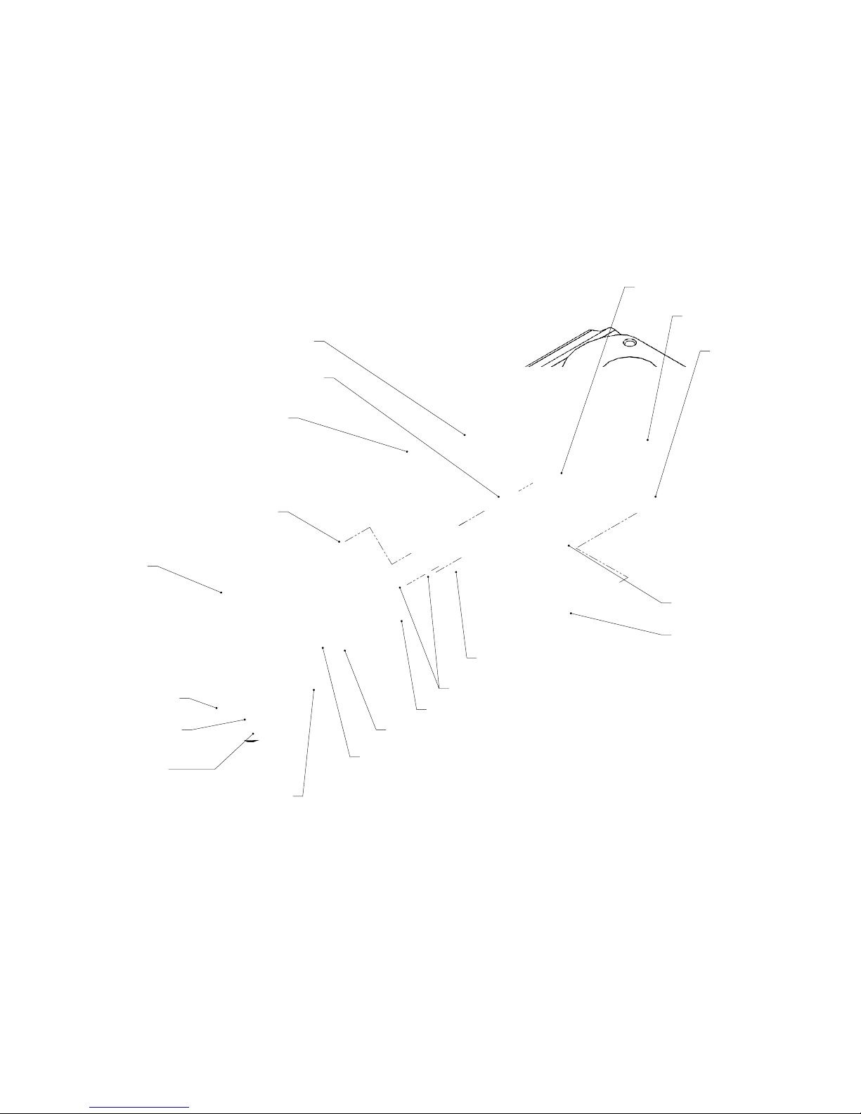
Str 12MJ-12MB Short and Oring (x2)
Spacer Sleeve (x2 Front - x2 Rear)
Set Screw .375-16x.5 (x8)
#12 Swivel Elbow and Oring (x2)
J Tube, Meter (x2)
SHCS 0.375-16x1.5 (x20)
(20ft-lbs Torque)
HEX BOLT 0.375-16x1.25 (x4)
(20 ft-lbs Torque)
Grease Zerk (x4)
End Cover Cap
(Front and Rear)
Spherical Bearing (x4)
Belleville Washer (x2)
Castle Nut
and Cotter Pin (x2)
(100ft-lbs Torque)
Bearing Cap Oring (x4)
End Plate Gasket
(qty varies)
HEX BOLT 0.5-13x1.5 (x16)
(45ft-lbs Torque)
T style Endplate (x2)
Str 12MJ-12MB Long and Oring (x4)
#12 Plug and Oring (x2)
Str 12MJ-12MB Short
and Oring (x2)
www.bearcatpumps.com
623-587-1350
U Style Diagram
4-8
Page 24
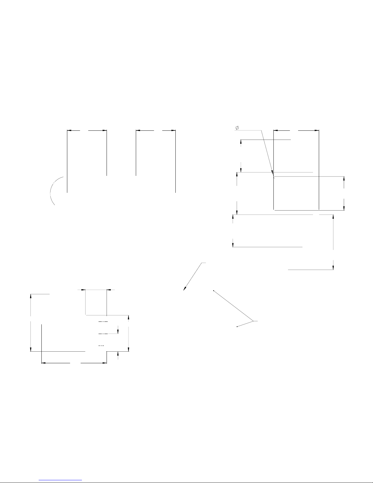
7.007.00
3.5" (300)
6.0" (450/600)
5.0" (300)
7.5" (450)
10.0" (600)
3.47" (N, W Model)
4.05" (V,B,C,T Model)
5.75" (R, U Model)
Dimensions vary see
shaft Diagram for details
2.83" (N, W Model)
4.05" (V,B,C,T Model)
5.75" (R, U Model)
8.00
3/4" (4pls)
6.41
10.16
11.57
3.16
3.75
Model 300 -
2.5" ANSI
150# Flange bolt circle
Model 450 -
3" ANSI
150# Flange bolt circle
Model 600 -
3" ANSI
150# Flange bolt circle
5/8-11 (4pls)
www.bearcatpumps.com
623-587-1350
Basic Dimensions
5-1
Page 25
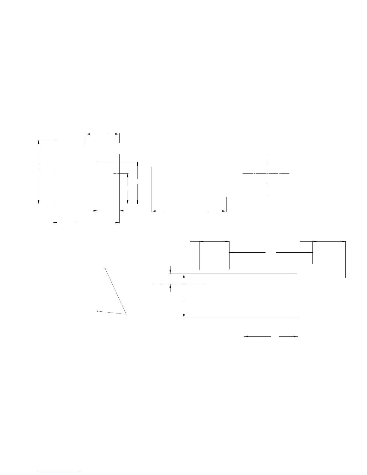
Dim varies depending
on shaft style
15.00
9.70
7.50
5.33"(R Model)
2.83"(N,W Model)
5.97" (R Model)
3.47" (N,W Model)
1.82
3.92
11.50
11.92
7.58
5.50
6.00
6" ANSI 150 Flange
3/4-10 (8) BC 9.5"
www.bearcatpumps.com
623-587-1350
900 Basic Dimensions
5-2
Page 26
1.499
0.375
.19
KeyWay
18"
X
- Extended Shaft
11.10" (300)
13.60" (450/600)
0.250
0.13"
Keyway
1.249
S
- Short Shaft
0.25
.13 (Standard)
0.31
.17 (B and W Models)
1.249
4.53
H -
Hydraulic Shaft
www.bearcatpumps.com
623-587-1350
Shaft Dimensions
5-3
Page 27
www.bearcatpumps.com
623-587-1350
Performance Curves
6-1
Pump Disp
300
Max RPM 600
Max GPM 180
Port Size 2.5in ANSI 150# Flange
300
0
100
200
300
400
500
600
700
0 30 60 90 120 150 180
Shaft Speed - RPM
Flow Rate (GPM)
Flow Rate (GPM)
0.0
2.0
4.0
6.0
8.0
10.0
12.0
0 30 60 90 120 150 180
Horse Power (Hp)
Flow Rate (GPM)
Power (neglecting viscosity)
25 PSI
50 PSI
100 PSI
Graph uses 1.0 service factor. This
value can vary based on condi
ons
Pump Disp
450
Max RPM 800
Max GPM 360
Port Size 4in Pump Flange*
*Bolt circle on flange is ANSI 3in 150#
*Port adapters available for 4in ANSI 150#, 8-bolt
450
0
100
200
300
400
500
600
700
800
900
0 60 120 180 240 300 360
Shaft Speed - RPM
Flow Rate (GPM)
Flow Rate (GPM)
0.0
5.0
10.0
15.0
20.0
25.0
0 60 120 180 240 300 360
Horse Power (Hp)
Flow Rate (GPM)
Power (neglecting viscosity)
25 PSI
50 PSI
100 PSI
Graph uses 1.0 service factor. This
value can vary based on condi
ons
Page 28
www.bearcatpumps.com
623-587-1350
Performance Curves
6-2
Pump Disp
600
Max RPM 800
Max GPM 480
Port Size 4in Pump Flange*
*Bolt circle on flange is ANSI 3in 150#
*Port adapters available for 4in ANSI 150#, 8-bolt
600
0
100
200
300
400
500
600
700
800
900
0 80 160 240 320 400 480
Shaft Speed - RPM
Flow Rate (GPM)
Flow Rate (GPM)
0.0
5.0
10.0
15.0
20.0
25.0
30.0
35.0
0 80 160 240 320 400 480
Horse Power (Hp)
Flow Rate (GPM)
Power (neglecting viscosity)
25 PSI
50 PSI
100 PSI
Graph uses 1.0 service factor. This
value can vary based on condi
ons
Pump Disp
900
Max RPM 800
Max GPM 720
Port Size 6" Pump Flange*
*Bolt circle on flange is ANSI 6in 150#
900
0
100
200
300
400
500
600
700
800
900
0 120 240 360 480 600 720
Shaft Speed - RPM
Flow Rate (GPM)
Flow Rate (GPM)
0.0
5.0
10.0
15.0
20.0
25.0
30.0
35.0
40.0
45.0
50.0
0 120 240 360 480 600 720
Horse Power (Hp)
Flow Rate (GPM)
Power (neglecting viscosity)
25 PSI
50 PSI
100 PSI
Graph uses 1.0 service factor. This
value can vary based on condi
ons
Page 29
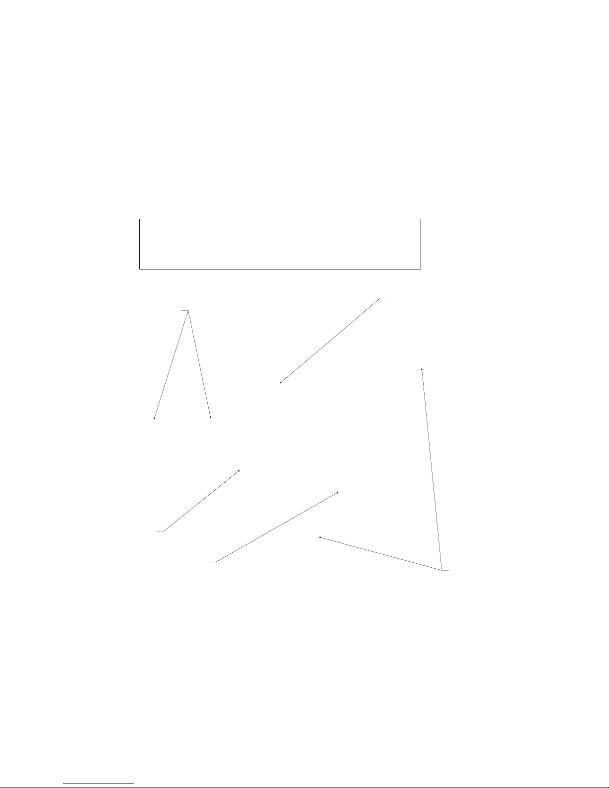
600VCX-RH
: Asphalt Pump
SC4-C-43-30
: Screen Box Assembly
with coarse screen pump adapter,
and jumper hose
S42-P-3V4.5-3V19
: Skid with
4.5" x 19" Pulleys, Belts, Bearing
and Guards
M34
: 4in Class 150 Flange Adapter
15S
: 15HP, 460V Inverter Duty Motor
4in Asphalt Unloading Skid with Screen Box
Below is an example of a skid for unloading apshalt tankers. Model
numbers for ordering shown in
bold text
.
www.bearcatpumps.com
623-587-1350
4in Asphalt Unloading Skid
7-1
Page 30
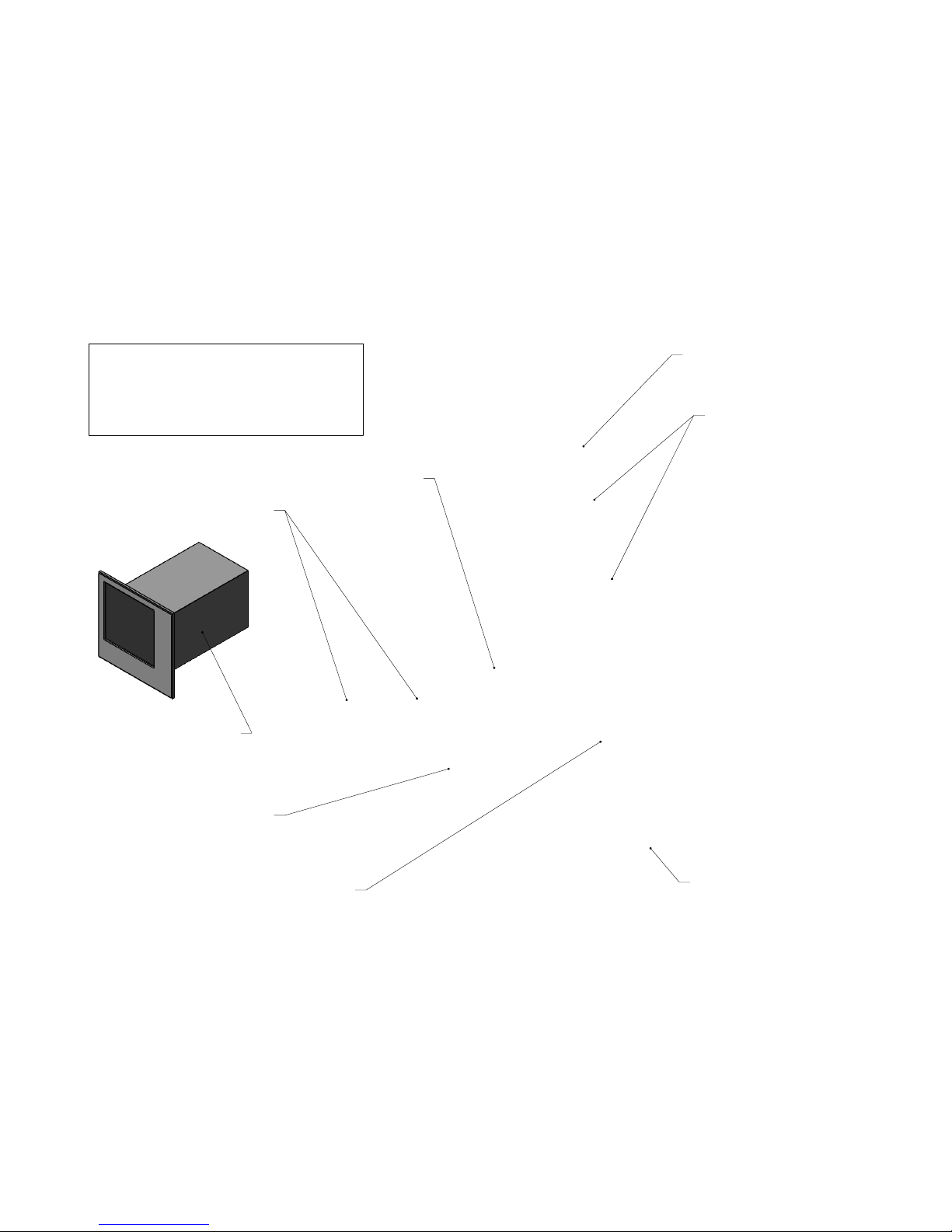
600RCX-RH
: Asphalt Pump
SC4-C-43-30
: Screen Box Assembly,
with coarse screen pump adapter
and jumper hose
S42-P-3V4.5-3V19
: Skid, with
4.5" x 19" Pulleys, Belts,
Bearing and Guards
C3030
: 3in Pump to
Meter Port Adapter
20S
: 20HP, 460V Inverter Duty Motor
and adjustment tray
CMF300-H:
Heat Block kit for
300 Series Micro Motion
CMF300M
: MicroMotion
CMF300M, with extended core
processor (4-wire)
3500 Transmitter
: MicroMotion
3500 Transmitter
3in Micro Motion Meter Skid
Below is an example of a Metering Skid for
Rubberized Asphalt. Model numbers for
ordering shown in
bold text
.
www.bearcatpumps.com
623-587-1350
3in Micro Motion Metering Skid
7-2
Page 31
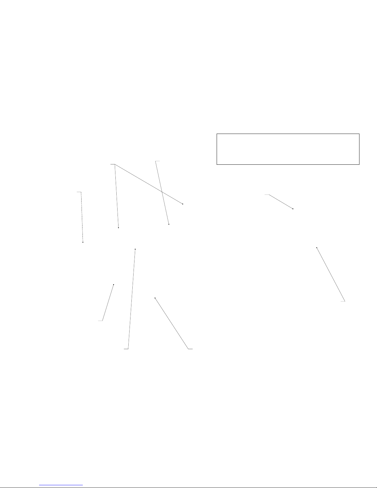
C3030
: Pump to Meter
Port Adapter
600VCX-RH-PB
: Asphalt Pump,
with Pillowblock Bearing
450TNH-RH-EA
: Asphalt Gear
Meter, with Encoder Coupler
and Guard option
SC4-C-43-30
: Screen Box
Assembly, with coarse
screen, pump adapter
and jumper hose
20S
: 20HP, 460V Inverter Duty
Motor and adjustment tray
M34
: 4in Class 150
Flange Adapter
BCP204
: 20HP, 460V VFD and
Panel includes; NEMA 12,13, ANSI
61, Hinged Door Enclosure,
External Controls and fuse block.
BCM-PNL
: Control Monitor PLC,
with sealed display window
4in Gear Metering Assembly
Below is an example of a 4in Gear Meter System for
Asphalt. Model numbers for ordering shown in
bold text
.
www.bearcatpumps.com
623-587-1350
4in Gear Metering Assembly
7-3
Page 32
600WWH-RH
: W Series pump,
with Hydraulic Motor and Split
Clamp Coupler.
600BMX-RH-OB
: B Series pump Extended
Shaft and Outboard Bearing. Good choice
for crude hauler truck, with PTO drive.
www.bearcatpumps.com
623-587-1350
Truck Pumps
7-4
 Loading...