

Page 1
PRODUCT MANUAL
BU100, BU400, BU800
beamlabs.io
REV0519
Page 2

TABLE OF CONTENTS
Congratulations on purchasing your beamUP garage
door opener. It will provide you with many years of
security, safety and convenience. This installation and
owner’s manual contains complete instructions for
installing and operating your garage door opener.
For warranty registration
beamlabs.io/warranty
Carton Contents
Before You Begin
Preparation + Tools Needed
Rail Assembly
Rail and Power Head Assembly
Trolley and Pulley Assembly
Installing Chain and Cable
Installing Belt
Attaching Sprocket Cover
Mounting Header Bracket
............................................1
.......................................... 2
............................ 3
.............................................. 4
........................ 5
............................. 6
.............................. 7
.............................................. 9
.............................. 1 1
.............................. 12
Attaching Rail and Mounting Door Bracket
Mounting Power Head to Ceiling
Attaching Door Arms
.................................... 15
Emergency Release Handle
Connecting Photo Eye Safety System
..................... 14
............................ 16
................17
Connecting Power and Aligning Photo
Eye Safety System
........................................ 18
.........13
Enabling/Disabling Motion Sensing
Security Lighting
Connecting Standard Door Control
........................................ 20
................. 2 1
Before We Start Programming The Opener
Travel Limit Adjustment – UP Limit
Travel Limit Adjustment – DOWN Limit
Setting the Force
........................................ 25
Final Adjustments and Testing
Handheld Remote Control
Wireless Keypad
........................................ 28
beamUP Smart Garage Door Controller
Using your Garage Door Opener
Troubleshooting
Maintenance
Warranty
Spare Parts
Opener Assembly Parts
......................................... 35
............................................. 37
.................................................. 38
............................................... 42
................................ 43
................... 23
.............. 24
........................ 26
............................ 27
............ 29
.................... 30
....... 22
Connecting Deluxe Door Control
..................... 19
Page 3
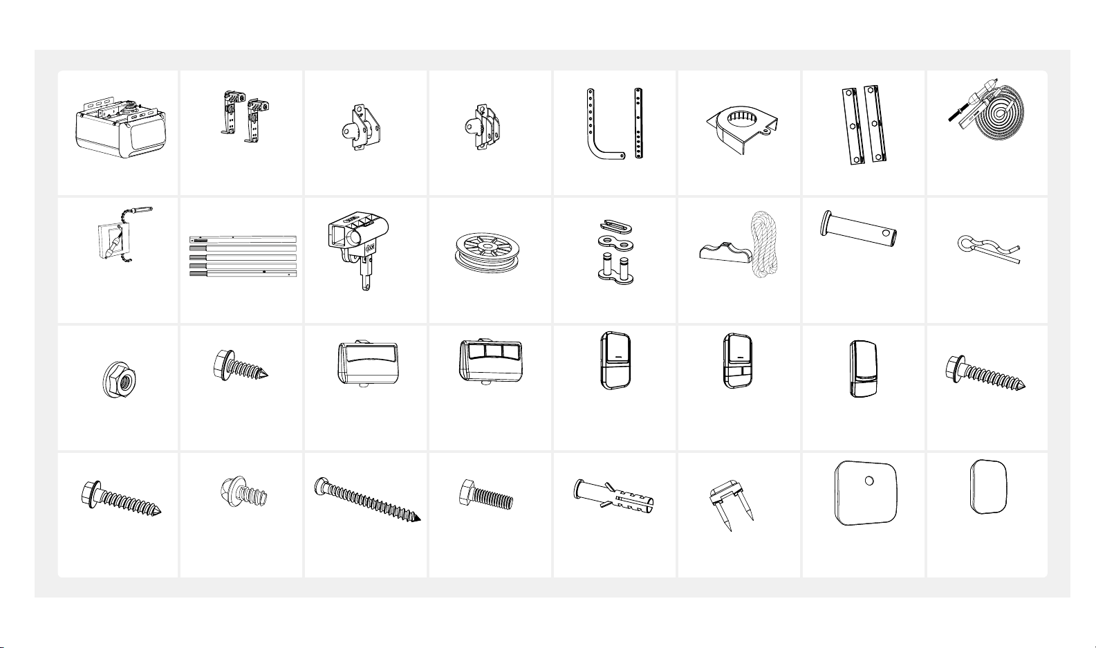
CARTON CONTENTS
Power Head
Photo Eye
Safety System
Header Bracket
Door Bracket
Door Arms
Trolley Sha/
Cable Assembly
(BU100 & BU400) Rail Trolley Pulley 1 x Master Link
7 x Flange Nut
4 x Screws
#12 x 1-1/4"
2 x Self-Threading
Screws
1/4" x 5/8"
1 x Self-Threading
Screw
#8-18 x 5/16
Single Button
Remote
(BU100)
6 x Screws
#6 x 1-3/8"
Three Button
Remote
(BU400 & BU800)
Standard
Door Control
(BU100)
6 x Bolts
5/16"– 18 x 1" 6 x Anchors
Sprocket Cover
Emergency
Release Handle
Deluxe
Door Control
(BU400 & BU800)
Insulated Staples
Hanging Bracket
Trolley Sha/
Belt Assembly
(BU800)
5 x Clevis Pins
2 x 5/ 16" x 1"
2 x 5/16" x 1-3/8"
1 x 3/8" x 1-3/4" 5 x Hitch Pins
Wireless Keypad
(BU800)
6 x Lag Screws
5/16" – 1/1/2"
Wireless Door
Controller
(BU400 & BU800)
Sensor
(BU400 & BU800)
beamlabs.io 1-800-436-9186 1
Page 4
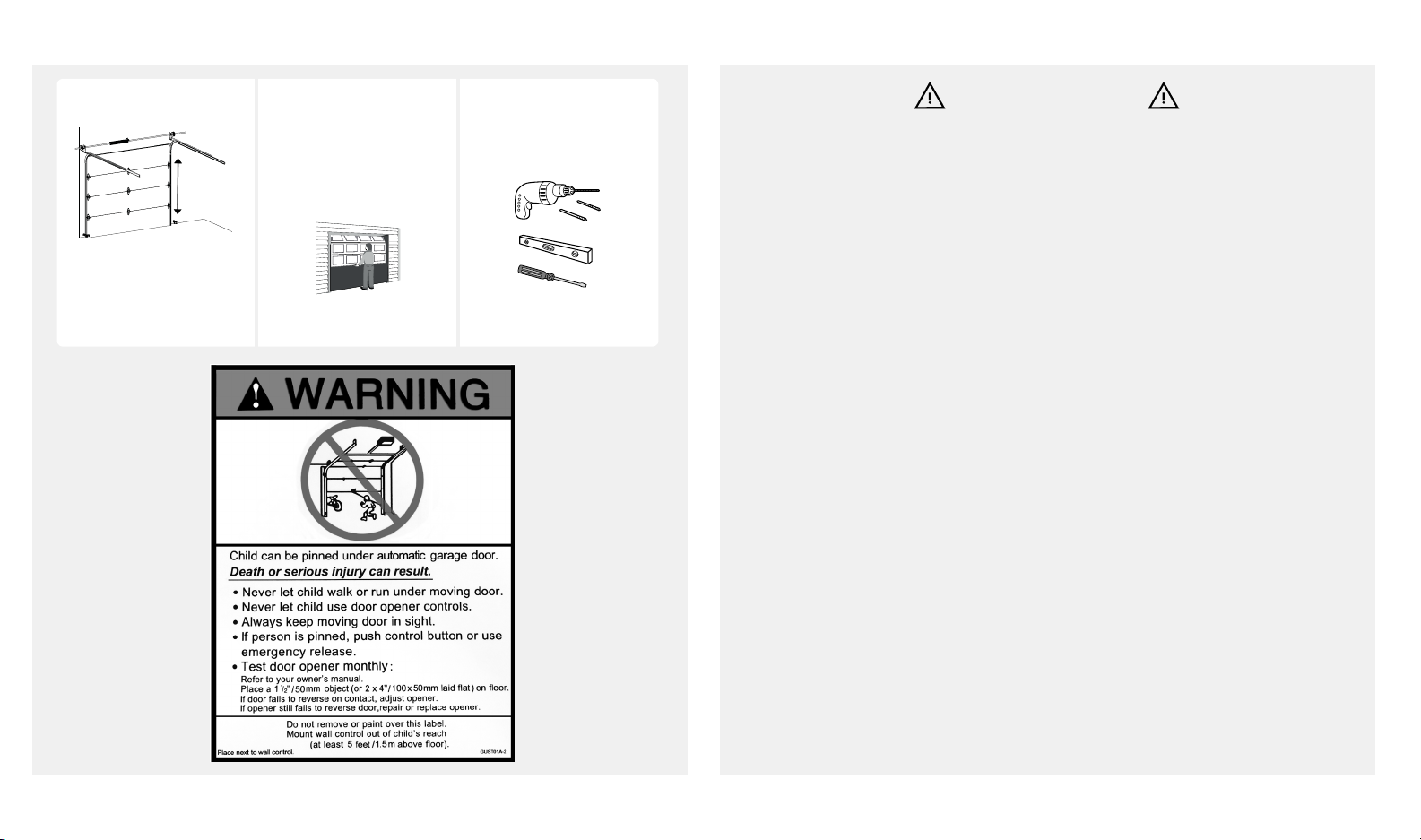
BEFORE YOU BEGIN SAFETY INSTRUCTIONS
Measure door height. Check mounting
locations.
Are additional
7.5 feet
(2.28 m)
If over 7.5 feet (2.28 m),
rail extension kit will be
needed.
reinforcement material
needed?
See page 3
Check your toolbox. Do
you have all the tools
needed?
See page 3
WARNING
To reduce the risk of severe injury or death:
1. READ AND FOLLOW ALL INSTALLATION INSTRUCTIONS.
2. Install only on a properly balanced garage door. An improperly balanced door has the
potential to inflict severe injury. Have a qualified service person make repairs to cables,
spring assemblies, and other hardware before installing the opener.
3. Remove all ropes and remove or make inoperative all locks connected to the garage
door before installing opener.
4. Where possible, install the door opener 7 feet (2.13 m) or more above the floor. For
products having an emergency release, mount the emergency release within reach, but
at least 6 feet above the floor and avoiding contact with vehicles to avoid accidental
release.
5. Do not connect the opener to source of power until instructed to do so.
6. Locate the door control button: (a) within sight of door, (b) at a minimum height of 5 feet
so small children are not able to reach it, and (c) away from all moving parts of the door.
7. Install the Entrapment Warning Label next to the wall-mount control button in a prominent location.
8. Aer installing the opener, the door must reverse when it contacts a
1-1/2 inch (3.8 cm) high object (or a 2x4 board) laid flat on the floor.
9. NEVER try to remove, loosen, move, or adjust garage door, cables, pulleys, brackets,
and door springs. All are under EXTREME tension.
2 beamlabs.io 1-800-436-9186
10. To reduce the risk of injuries to persons – use this operator only with residential sectional
garage doors. Only enable the unattended operation feature when installed with a
sectional door. The Smart Door Controller should be used only on sectional doors and
with garage door openers made aer 1993 with a photo eye safety system.
Page 5
PREPARE GARAGE DOOR FOR INSTALLATION
DO NOT REUSE PARTS AND
WIRING FROM AN OLD
OPENER!!!
BEFORE beginning
installation:
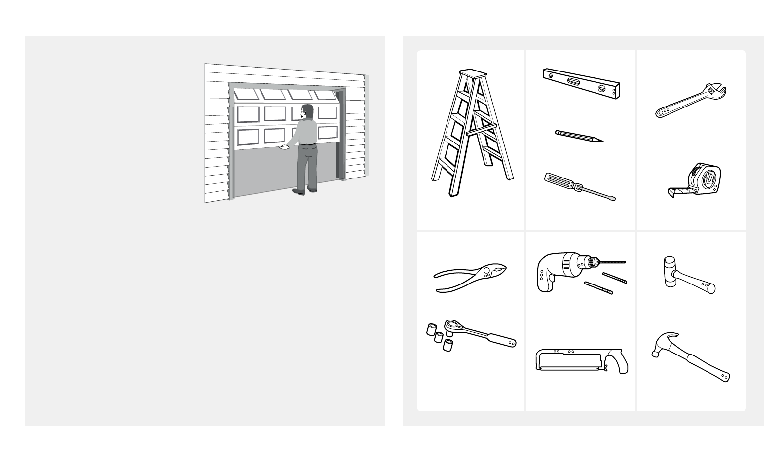
TOOLS NEEDED
Level
Adjustable Wrench
1. Disable locks and disengage
trolley from current opener.
2. Perform the following door
test to ensure your door
is balanced and in good
working condition.
Make sure garage door is fully closed before you start the installation
To test your garage door:
1. Raise and lower the door to check if there is any sticking or binding.
2. Check for loose hinges, damaged rollers, frayed cables and damaged or
broken springs.
3. Li the door approximately halfway and release. The door should stay at
that point under proper spring tension.
Call a qualified garage door service technician if your door binds, sticks or
is unbalanced.
Step Ladder
Pliers
Ratchet with
1/4", 7/16" and
1/2" sockets
Pencil
Screwdriver
5/16" Drill Bits
Hack Saw
Tape Measure
Rubber MalletDrill 3/16" and
Hammer
beamlabs.io 1-800-436-9186 3
Page 6
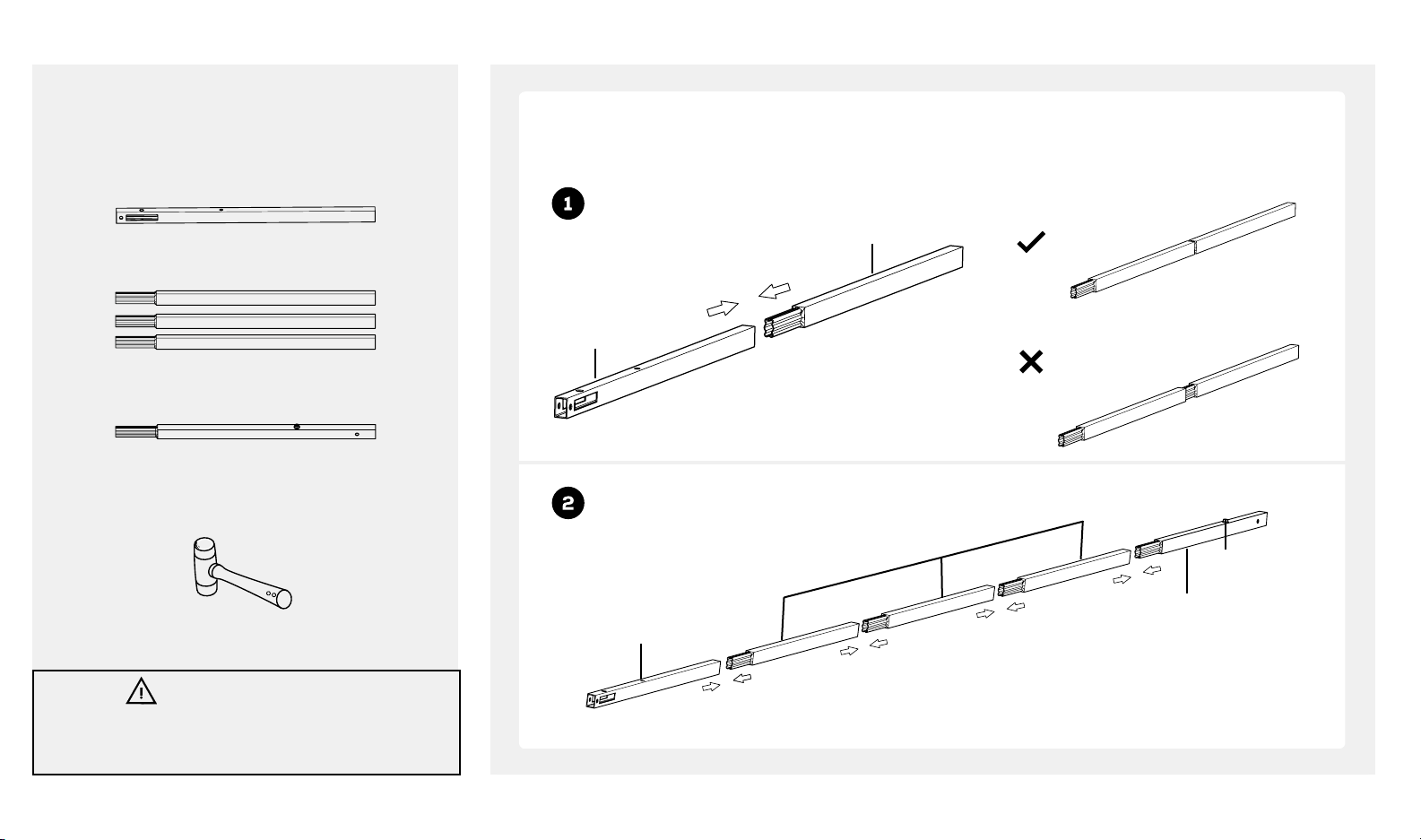
RAIL ASSEMBLY
Look in the box for:
Rail – Header Segment
Connect rails starting with the rail header segment. To apply additional force tap gently on the end of the
connected rail segments with a rubber mallet or on padded flooring.
Securely connected by applying force
Rail- Middle
Segment
Rail – Middle Segments x3
Rail – End Segment
Tools needed:
Rubber Mallet
CAUTION
To prevent INJURY from pinching, keep hands and fingers
away from joints when assembling the rail.
Rail- Header
Segment
Rail- Header
Segment
Rail- Middle Segments x3
Right
Loosely connected
Wrong
Stop Bolt
Rail- End Segment
4 beamlabs.io 1-800-436-9186
Page 7
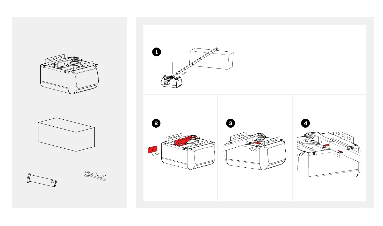
RAIL AND POWER HEAD ASSEMBLY
Look in the box for:
Use garage door opener carton to assemble rail to power head. Use packing material as protective base for
power head.
Power Head
Rail Bracket
Clevis Pin
5/16" x 1-3/8"
Opener Carton
Hitch Pin
Insert rail-end segment into
bracket as shown.
Insert clevis pin into rail
bracket as shown.
Insert hitch pin into clevis pin
as shown.
beamlabs.io 1-800-436-9186 5
Page 8
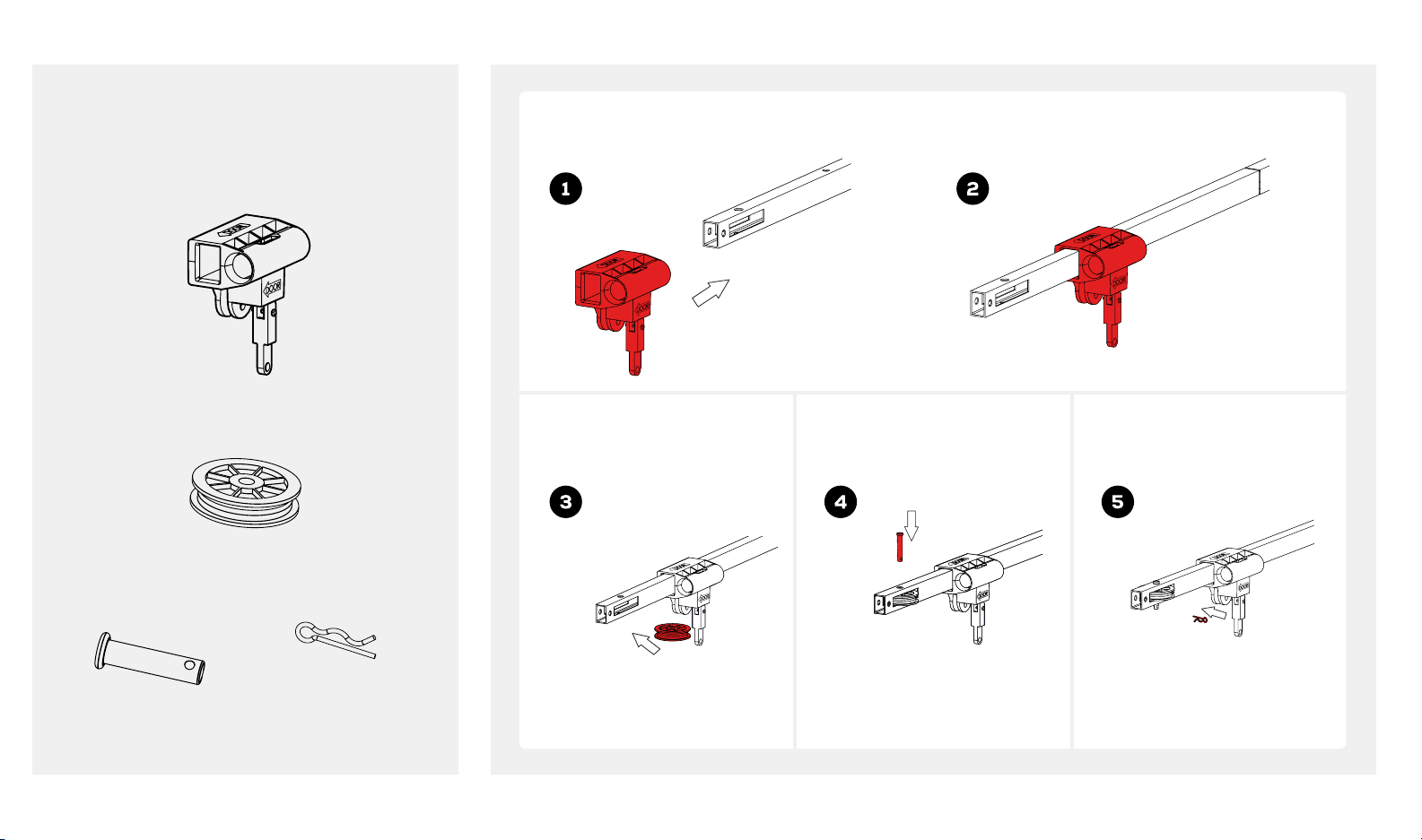
TROLLEY AND PULLEY ASSEMBLY
Look in the box for:
Trolley
Slide trolley onto the rail. Make sure the arrow on the trolley points toward the door.
Pulley
Clevis Pin
3/8" x 1-3/4"
6 beamlabs.io 1-800-436-9186
Hitch Pin
Insert pulley into the pulley
slot.
Insert clevis pin through rail
hole and pulley.
Insert hitch pin into clevis pin.
Page 9
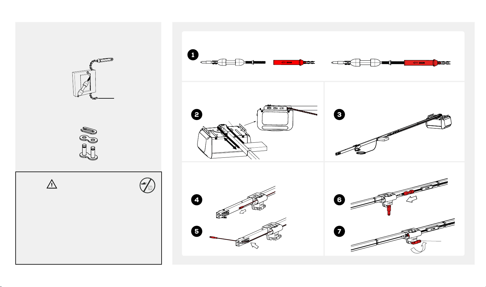
INSTALLING CABLE AND CHAIN (BU100, BU400)
Look in the box for:
Trolley Sha/Chain Assembly
End of
Chain
Master Link
WARNING
To prevent SERIOUS INJURY:
• DO NOT connect power until instructed.
• Keep hands and fingers clear from sprocket during
operation.
• Wear gloves when installing chain and cable.
• Keep hands and fingers away from joints and
possible sharp edges.
Loosely attach trolley sha with chain connector. 5 complete turns will be sufficient.
Align end of chain around sprocket and extend chain
past chassis, approximately 7" (17.8 cm). Sprocket teeth
must engage the chain.
Chassis
7"
(17.8 cm)
Insert cable through circular hole in trolley. Pull
cable through pulley slot and toward power
head.
Pull chain with box along the rail towards trolley and
then remove box.
Pull trolley lock lever down to unlock. Insert trolley
sha through the trolley and pull lever back up.
Trolley in
engaged
position
beamlabs.io 1-800-436-9186 7
Page 10
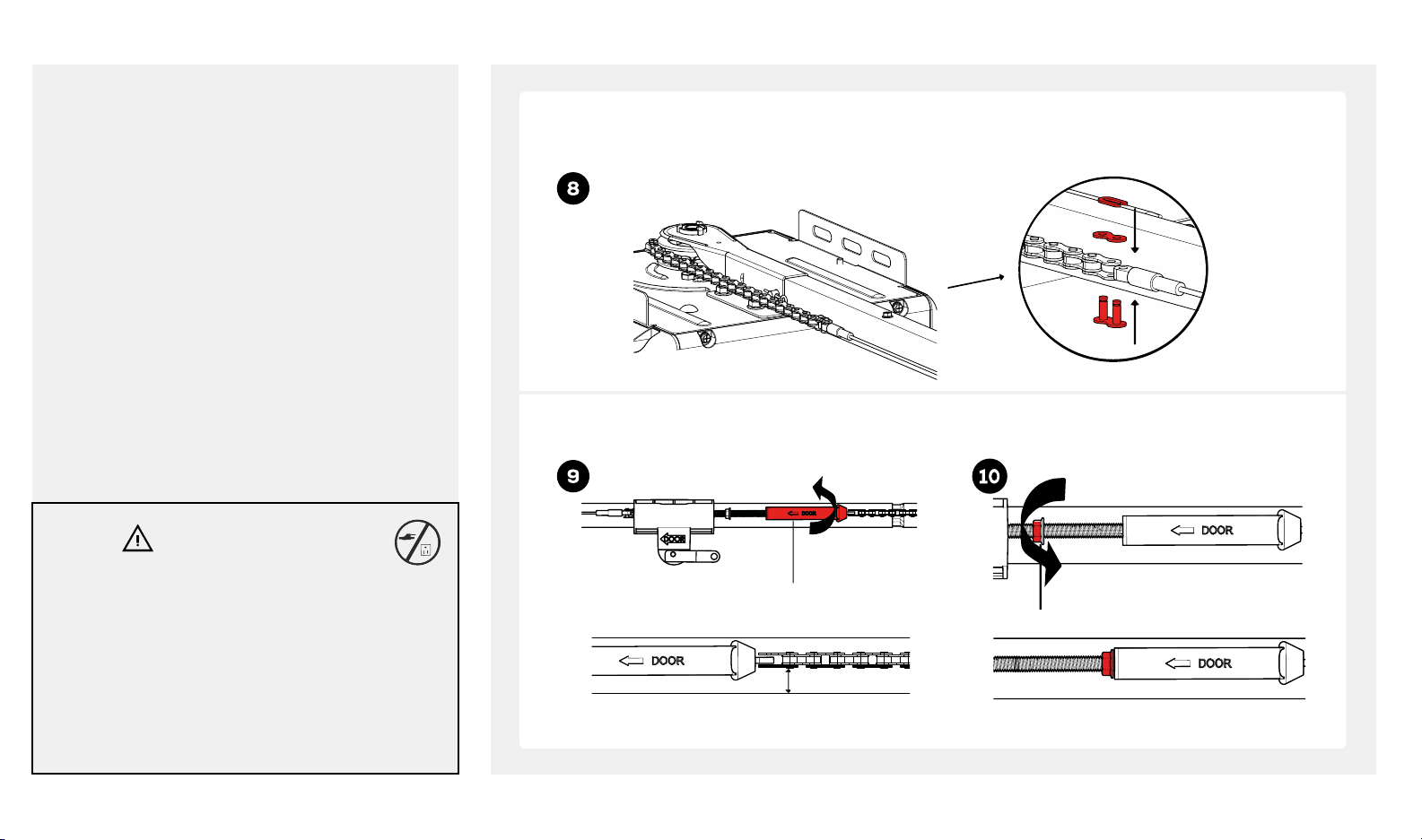
INSTALLING CABLE AND CHAIN (BU100, BU400)
Bring cable and chain together and connect with master link. Check to make sure the chain is not twisted. If
chain and cable are not close enough to connect with master link, loosen chain-to-cable connector to create
more slack.
Adjust chain tension by turning chain-to-cable connector until chain is about 1/4 inch (.64cm) above the base of
rail. Once proper tension is achieved tighten lock nut against chain-to-cable connector.
WARNING
To prevent SERIOUS INJURY:
• DO NOT connect power until instructed.
• Keep hands and fingers clear from sprocket during
operation.
• Wear gloves when installing chain and cable.
• Keep hands and fingers away from joints and
possible sharp edges.
Chain-to-cable connector
1/4 inch
(.64 cm)
Tighten until...
Nut
8 beamlabs.io 1-800-436-9186
Page 11
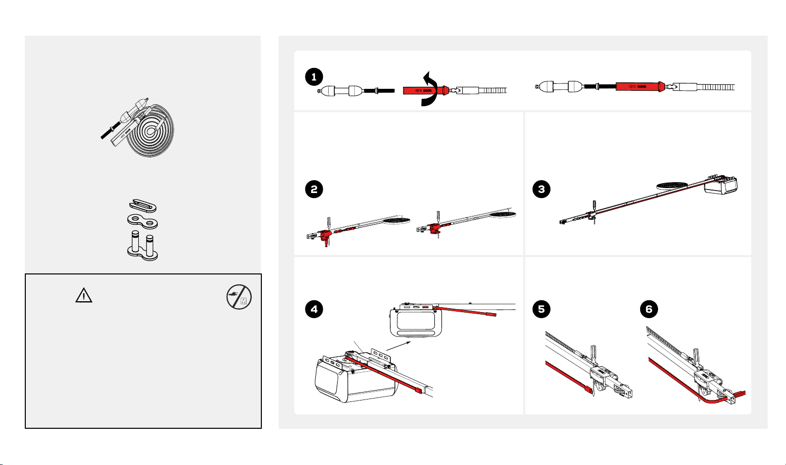
INSTALLING BELT (BU800)
Look in the box for:
Trolley Sha/Belt Assembly
Master Link
WARNING
To prevent SERIOUS INJURY:
• DO NOT connect power until instructed.
• Keep hands and fingers clear from sprocket during
operation.
• Wear gloves when installing chain/belt and cable.
• Keep hands and fingers away from joints and
possible sharp edges.
Loosely attach trolley sha with belt connector. 5 complete turns will be sufficient.
Pull trolley lock lever down to unlock. Insert screwdriver
into the hole located on the rail-header segment. Slide
the trolley up to the screwdriver. The trolley must stay in
this position for proper alignment of the belt. Insert the
trolley sha through the trolley and pull lever back up.
Sprocket teeth must engage the belt. Continue
pulling belt towards trolley.
Chassis
Pull belt along the rail towards power head and
loop belt around the belt sprocket.
Insert belt through pulley slot and toward power
head. The ribbed side must contact the pulley and
should be facing inwards.
beamlabs.io 1-800-436-9186 9
Page 12
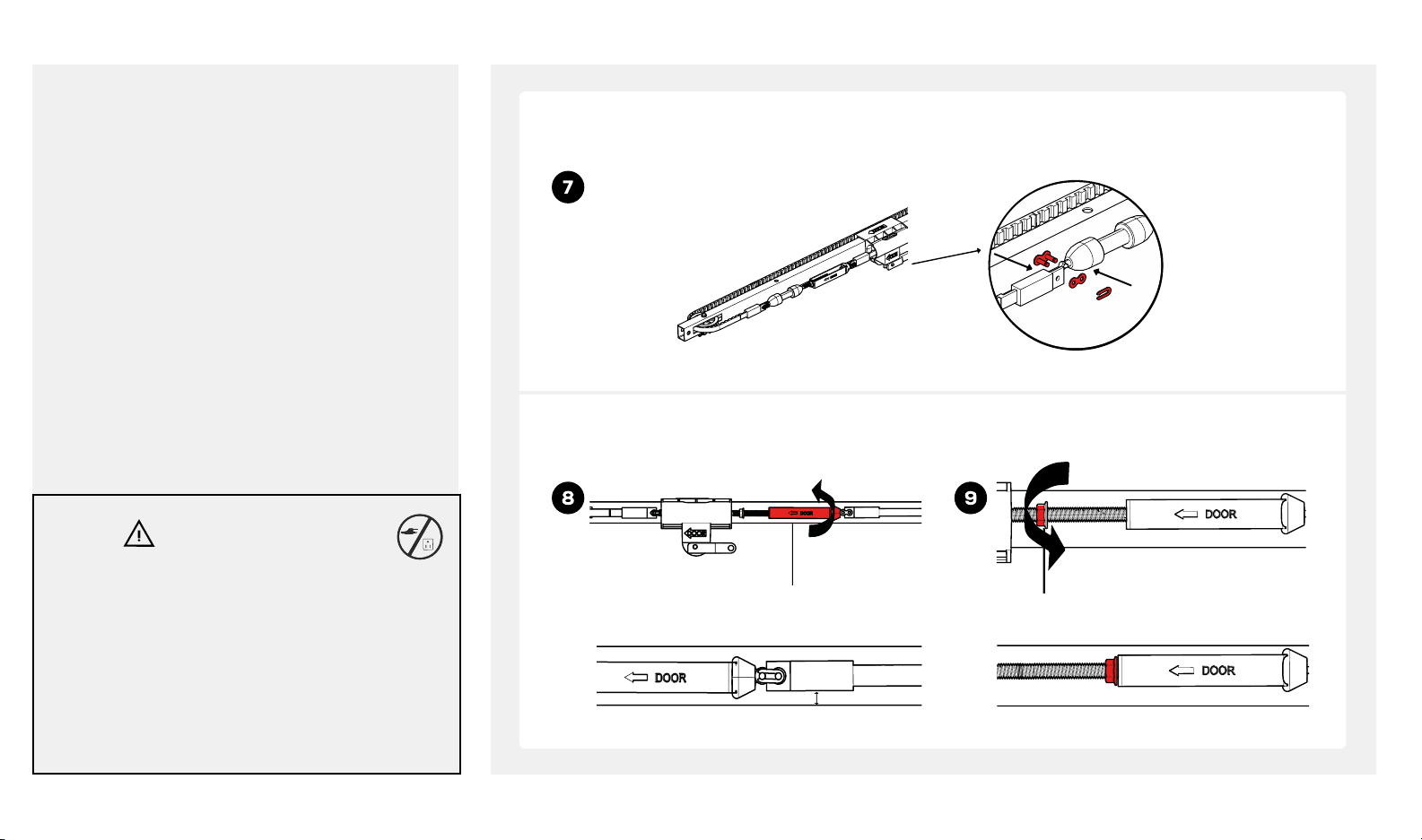
INSTALLING BELT (BU800)
WARNING
To prevent SERIOUS INJURY:
• DO NOT connect power until instructed.
• Keep hands and fingers clear from sprocket during
operation.
• Wear gloves when installing chain/belt and cable.
• Keep hands and fingers away from joints and
possible sharp edges.
Bring belt and trolley sha together, check to make sure the belt is not twisted. Connect belt and trolley sha
with master link. If belt connector and trolley sha are not close enough to connect with master link, loosen belt
connector to create more slack.
Adjust belt tension by turning belt connector until belt is about 1/4 inch (.64cm) above the base of rail. Once
proper tension is achieved tighten lock nut against belt connector.
Belt connector
Tighten until...
1/4 inch
(.64 cm)
Nut
10 beamlabs.io 1-800-436-9186
Page 13
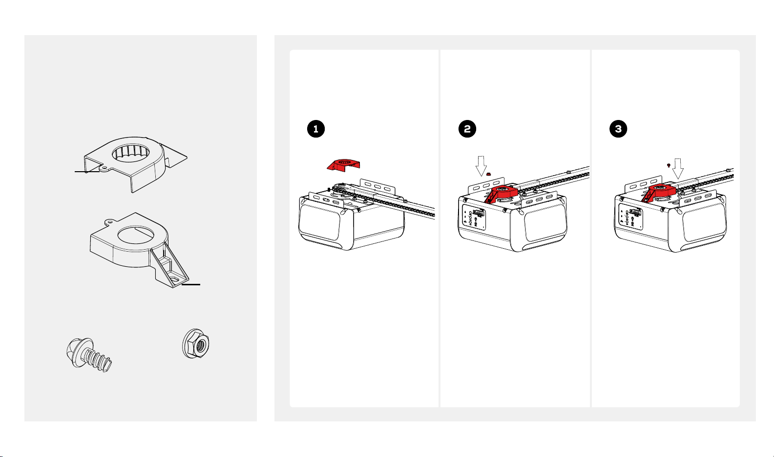
ATTACHING SPROCKET COVER
Look in the box for:
Sprocket Cover
Front
Ta b
Rear Tab
Attach sprocket cover to
power head.
Fasten rear tab with flange nut
on top of steel chassis.
Fasten front tab with selfthreading screws to hole on
top of rail bracket.
Self-Threading Screw
#8-18 x 5/16
Flange Nut
beamlabs.io 1-800-436-9186 11
Page 14
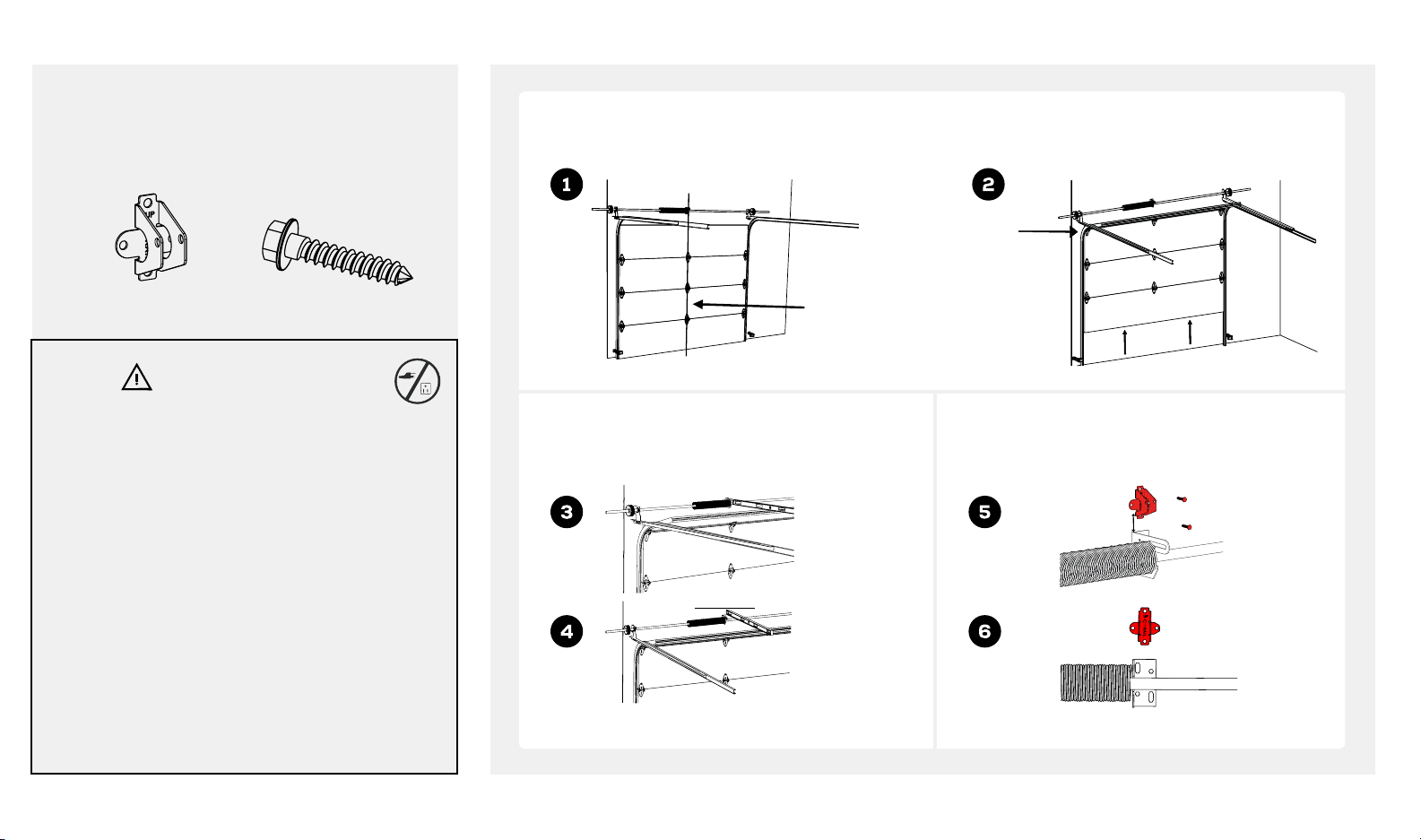
MOUNTING HEADER BRACKET
Look in the box for:
Header Bracket 2 x Lag Screws
5/16" x 1-1/2"
WARNING
Mark the center line above the door with a pencil. Open door to the highest point of travel.
Highest Point
of Travel
Center Line
To prevent SERIOUS INJURY:
• DO NOT connect power until instructed.
• The header bracket MUST be SECURELY fastened
to the structural support on the mounting wall or
ceiling, otherwise other door may not reverse when
required. DO NOT install the header bracket over
drywall.
• Concrete anchors MUST be used when mounting
the header bracket into masonry.
• NEVER try to loosen, move or adjust garage door
springs, cables, pulleys, brackets, or hardware.
• Contact a qualified garage door service technician
if your door binds, sticks or is unbalanced. An
unbalanced door might not reverse when required.
12 beamlabs.io 1-800-436-9186
Take a level, measure and mark highest point of the
door on the wall. Raise level to clear torsion bar if
required, then mark highest point.
Measure 2 - 1/4 inch (5.7 cm), mark two holes of
header bracket. Drill two holes and fasten header
bracket using screws.
2-1/4 inch
(5.7cm)
Page 15
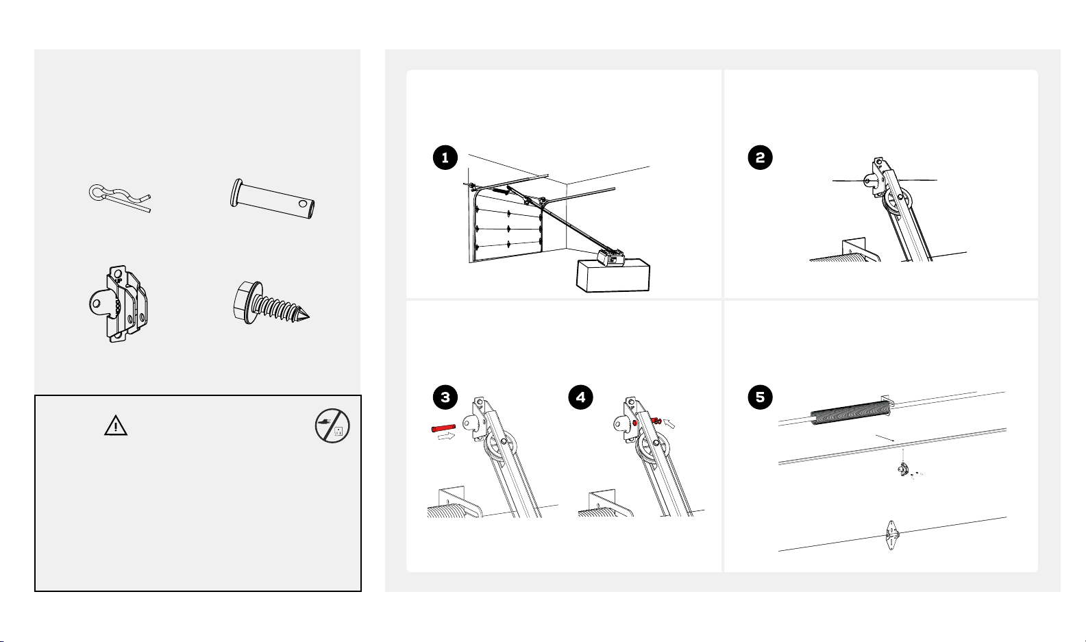
ATTACHING RAIL AND MOUNTING DOOR BRACKET
Look in the box for:
Use garage door opener carton to support power
head. Rail header segment end should be pointing
to header bracket.
Hitch Pin Clevis Pin
5/16" x 1-3/8"
Door Bracket 2 x Self-Threading
Screws - 1/4" x 5/8"
Align header rail hole to header bracket hole.
Header
Rail Hole
Header
Bracket Hole
CAUTION
To prevent SERIOUS INJURY:
• DO NOT connect power until instructed.
• REINFORCEMENT is recommended for fiberglass,
aluminum or lightweight steel garage doors
BEFORE installing the door bracket. Contact your
door manufacturer for reinforcement options.
Connect header rail and header bracket with clevis
pin and secure with hitch pin.
Position door bracket on centerline of the top
garage door panel. Door bracket should be 2-4
inches (5-10 cm) below the top edge of door panel.
Door Edge
2" - 4" (5 - 10 cm)
beamlabs.io 1-800-436-9186 13
Page 16
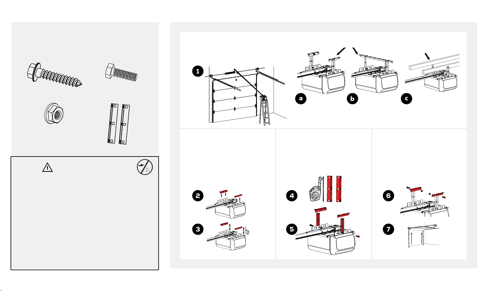
MOUNTING POWER HEAD TO CEILING
Look in the box for:
4 x Lag Screws
5/16"-18 x 1"
4 x Flange Nut Hanging Brackets
4 x Bolts
5/16" - 18 x 1"
WARNING
To prevent SERIOUS INJURY:
• DO NOT connect power until instructed.
• Install the opener at least 7 feet (2.13m) above the
floor.
• Fasten the opener SECURELY to STRUCTURAL
SUPPORT of the garage to prevent falling.
• If installing brackets to masonry, concrete anchors
(not provided) MUST be used.
• To prevent damage to garage door surface, rest
garage door opener rail on 2x4 placed on top
section of door.
Li power head onto ladder. Position and
align power head with rail assembly to
centerline. Fully open door manually and
place a 2x4 under the rail.*
Use lag screws to attach angle
iron to the structural supports
before installing the garage
door opener onto a finished
ceiling. Measure the distance
from each side of the power
head to the angel iron.
Angle Iron
(not included)
Finished Ceiling Finished Ceiling
Three most common installation options. Determine the mounting
option that works best for you.
Cut both hanging brackets to
appropriate length. Attach the
end of each hanging bracket
to the angle iron with 5/16" x
1" bolts and flange nuts.
Attach power head to hanging
brackets with 5/16" x 1" bolts
and flange nuts. Remove 2x4
and manually close the door.
If the door hits the rail, raise
header bracket.
Structural
Support
Unfinished Ceiling
Open
14 beamlabs.io 1-800-436-9186
*A 2x4 is ideal for setting the distance between the rail and the door.
Page 17
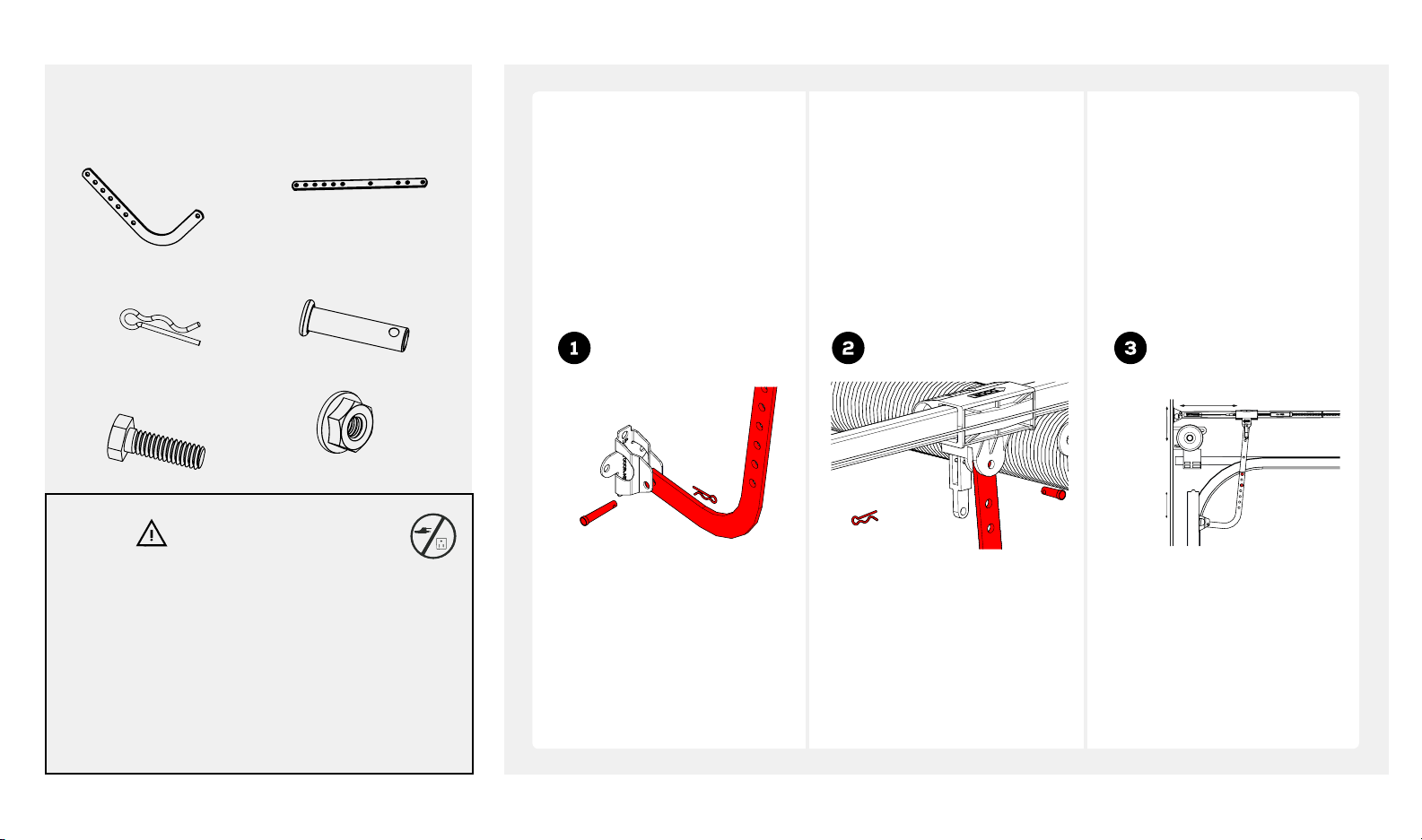
ATTACHING DOOR ARMS
Look in the box for:
Curved Door Arm Straight Door Arm
2 x Hitch Pins 2 x Clevis Pins
5/16" x 1"
Close your garage door and
disengage trolley. Fasten
curved door arm to the door
bracket with 5/16" x 1" clevis
pin and secure with hitch pin.
Fasten straight door arm to
trolley with a 5/16" x 1" clevis
pin and secure with hitch pin.
Attach door arms with two
5/16" bolts and flange nuts.
Bring straight and curved door
arm together. Find two pairs
of holes that line up and join
sections with two 5/16" bolts
and flange nuts. Select holes as
far apart as possible to increase
door arm rigidity.
2 x Bolts
5/16" - 18 x 1"
2 x Flange Nuts
WARNING
To prevent SERIOUS INJURY:
• DO NOT connect power until instructed.
• Keep hands and fingers away from the sprocket
during operation.
• Wear gloves when installing chain/belt and cable.
• Keep hands and fingers away from joints and
possible sharp edges.
8" (20.3 cm)
3"
(7.6 cm)
2"- 4"
beamlabs.io 1-800-436-9186 15
Page 18
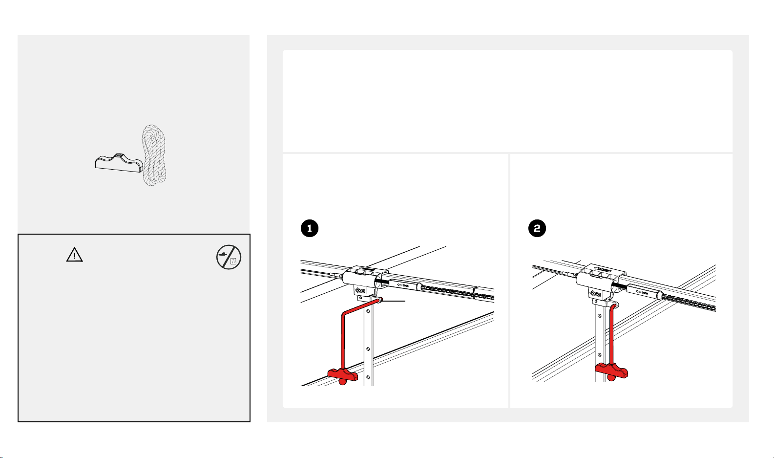
INSTALLING EMERGENCY RELEASE HANDLE
Look in the box for:
* VERY IMPORTANT! *
Emergency release handle must clear all vehicles. An emergency release handle set too low may get caught
by the vehicle and cause damage to the opener. Measure from the floor to the top of your vehicle and set the
Emergency Release Handle
emergency release handle above this measurement.
WARNING
To prevent SERIOUS INJURY:
• In case of power outage or door obstruction, PULL
EMERGENCY HANDLE to release door from opener.
• When trolley is disengaged, (trolley lever pointing
down) door can be operated manually.
• To engage, flip the trolley lever up so it is horizontal.
Trolley will automatically re-engage when garage
door opener is activated.
• DO NOT use emergency handle to pull the door
open or close.
16 beamlabs.io 1-800-436-9186
Thread end of rope through handle and secure with
an over hand knot. Thread end of the rope through
hole in trolley lever.
Hole in
Trolley
Lever
Measure rope length so the handle is 6 feet
(183 cm) above the floor and is clear from the top of
your vehicle. Secure with a overhand knot.
Page 19
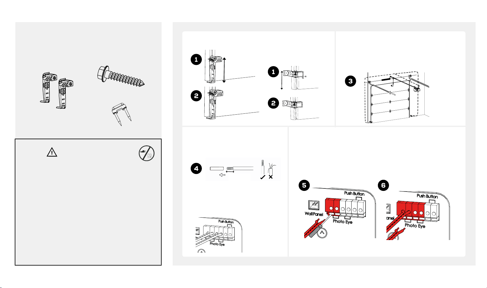
CONNECTING PHOTO EYE SAFETY SYSTEM
Look in the box for:
Mount photo eyes using #12 x 1-1/4" screws provided. Run wire to power head. Use insulated staples
Photo Eyes
4 x Screws
#12 x 1-1/4"
Insulated Staples
Photos eyes
should be no
more than 6
inches (15.2 cm)
above the floor.
Floor mounting
(concrete anchors
not provided)
Alternative mounting location:
Door track mounting
to secure photo eye wires to wall and ceiling.
Take care not to puncture the wires while
securing staples.
WARNING
To prevent SERIOUS INJURY or DEATH from
electrocution:
• Power MUST NOT be connected until instructed.
• The garage door opener will not operate until the
photo eye safety system is properly connected and
aligned.
• Install the photo eye safety system NO higher than
6 inches (15 cm) above the floor.
• No part of garage door or other objects should
obstruct the photo eye safety system during doorclosing.
* VERY IMPORTANT! *
Strip 7/16 inch (1 cm) of insulation
from the end of the wire.
7/16 inch
(1 cm)
Each pair of terminals MUST be
connected with one white wire and
one striped wire (non-polarized) from
the SAME photo eye.
Cut and discard excess wire. Use small flat head screwdriver to
push in grey tab on the terminal block located on the rear panel
of the power head. Insert 1/2 inch (1.2 cm) of the wire into the
terminal while pushing in the tab.
beamlabs.io 1-800-436-9186 17
Page 20
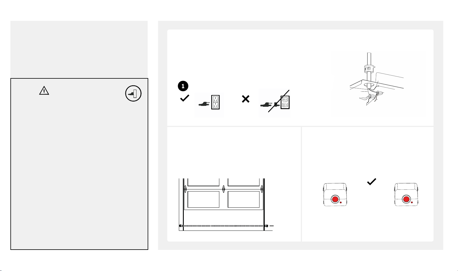
CONNECTING POWER AND ALIGNING PHOTO EYE SAFETY SYSTEM
Conduit with wire
Line (Black)
Neutral (White)
White
Black
(From Transformer)
Ground (Green/Yellow)
Ground Screw (Green)
Brown
Wire nut
NOTICE:
The garage door opener cannot be programmed
and will not close the door until photo eye safety
system are installed and aligned.
* DO NOT OPERATE OPENER AT THIS TIME *
Plug power head into a grounded outlet ONLY. If there
is no grounded outlet present, call a qualified electrician
to replace the outlet. Use of a surge protector is highly
recommended.
WARNING
To prevent SERIOUS INJURY or DEATH from
electrocution or fire:
• Power MUST be DISCONNECTED BEFORE
proceeding with permanent wiring procedures.
• Garage door opener installation and wiring MUST
be in compliance with all local electrical and
building codes. Make sure the opener is ALWAYS
grounded.
• NEVER use an extension cord, 2-wire adapter or
modify the power plug in any way to make it fit the
outlet.
Right
Wrong
When the photo eye safety system is properly
aligned green LED (emitter) will emit a steady green
light and the red LED (sensor) will emit a steady red
light. The path of the invisible light beam MUST NOT
be obstructed. No part of the garage door or any
hardware should interfere or block either sensor.
Green LED (emitter) will flash until it is aligned with
red LED (sensor). Red LED will not illuminate until it
is aligned with green LED.
Emitter
Green LED ON
For Permanent Wiring ONLY
Sensor
Red LED ON
To prevent SERIOUS INJURY or DEATH from a closing
garage door:
• The photo eye safety system MUST be installed
BEFORE connecting power.
• The photo eye safety system MUST be properly
connected and aligned BEFORE operating the
opener.
18 beamlabs.io 1-800-436-9186
Invisible
Light Beam
Aligned
Steady Red &
Green LED
The emitter generates the invisible light beam, and
the sensor receives the invisible light beam.
Page 21
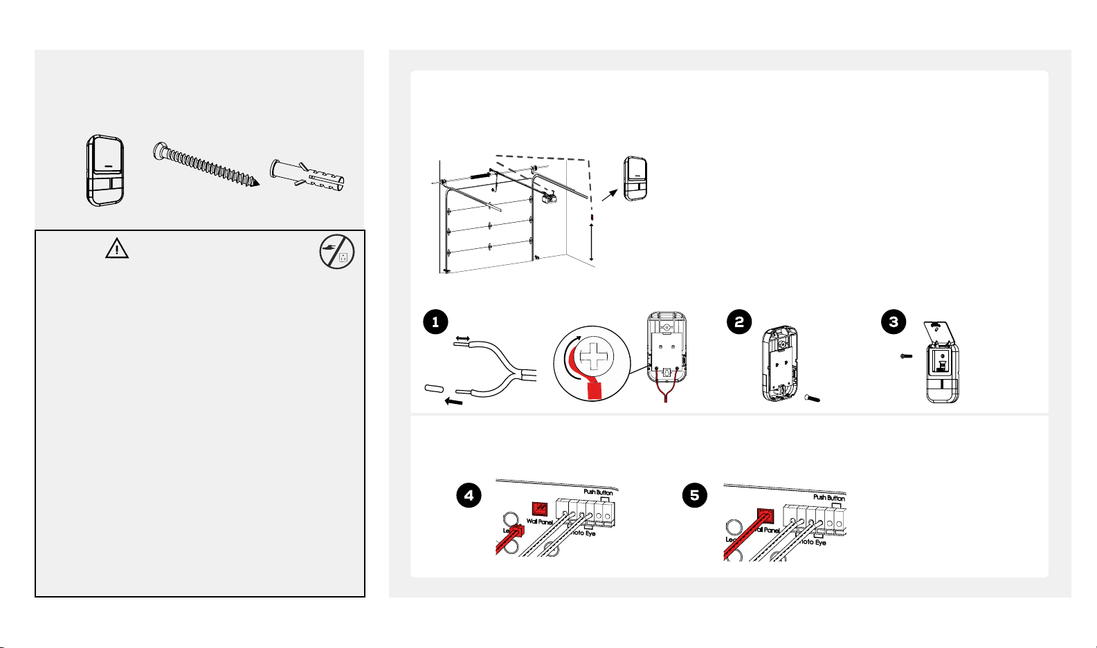
CONNECTING DELUXE DOOR CONTROL (BU400, BU800)
Look in the box for:
1. Strip 7/16 inch (11 mm) of insulation from wire and separate wires.
Deluxe Door
Control*
2 x Lag Screws
#6 x 1-3/8"
2 x Anchors
WARNING
To prevent SERIOUS INJURY or DEATH from electrocution or fire:
• Be sure power is NOT connected BEFORE installing door
control.
• Connect door control ONLY to 12 VOLT low voltage wires.
To prevent SERIOUS INJURY or DEATH from a closing garage
door:
• Install door control within sight of garage door, at a minimum
height of 5 feet (1.5 m) so small children are not able to reach
it, and away from ALL moving parts of door.
• NEVER permit children to operate or play with door control
or remote controls.
• Activate garage door opener ONLY when door can be seen
clearly, is properly adjusted, and there are no obstructions to
door travel.
• ALWAYS keep a moving garage door in sight until completely
closed. NEVER cross path of moving garage door.
Wire deluxe door control to power
2. Connect one wire to each of the two screws on the back of the
head as shown.
Deluxe Door
Control
3. Mark the location of bottom mounting hole and drill 5/32 inch hole.
4 Install the bottom screw and allow 1/8 inch (3 mm) to protrude
5. Position bottom hole of door control over the screw and slide
Min. 5 feet
(1.52 m)
above floor
6. Li actuation button and mark the top hole. Remove the door
7. Position bottom hole of door control over the screw and slide
1/4" (6mm)
Connect plug from deluxe door control to wall panel outlet on the back panel of the power head.
**If using pre-existing wire you may cut off plug and splice to existing wire**
door control. *DO NOT RECOMMEND USING PRE-EXISTING
WIRE*
from wall. Note: Use anchors if mounting to drywall.
down into place.
control from wall and drill 5/32 inch hole for top screw
down into place. Fasten the top screw
Top screw
Bottom screw
See how to use deluxe door
control on page 20.
*NOTE: Your opener will contain one of two door controls. Follow the instructions corresponding to the control provided.
beamlabs.io 1-800-436-9186 19
Page 22
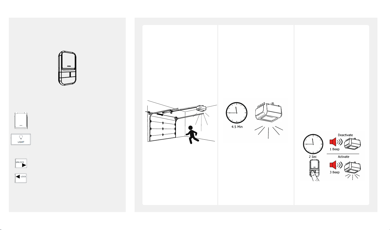
MOTION ACTIVATED SECURITY LIGHTING (BU400, BU800)
Look in the box for:
Deluxe Door Control
Using the Deluxe Door Control
ONLY aer Installation is completed
Door-Press and release to open/close the door.
Press and hold to activate/deactivate motion sensing
security lighting. Turns the courtesy light on/off.
Vacation Lock
Unlock - Slide lock button to the right to enable all
remotes, door control and accessories.
Lock - Slide lock button to the right to disable all
remotes, door control and accessories.
Security lighting is activated
and remains on for 4.5
minutes when garage door
opener is operated.
Motion sensing is turned on
by default and will activate
security lighting when motion
is detected within the garage.
Security lighting will remain
illuminated for 4.5 minutes or
for as long as there is motion in
the garage.
*Note - if you wish to turn off
security lighting when motion
sensing is activated press the
“LIGHT” button and security
lighting will turn off and remain
off for 25 seconds. If motion
is detected aer 25 seconds,
security lighting will turn on.*
To deactivate motion sensing:
Press and hold “LIGHT" button
for 2 seconds. The power head
will beep once to indicate
motion sensing has been
deactivated.
To active motion sensing: Press
and hold “LIGHT” button for 2
seconds. The power head will
beep 3x to indicate motion
sensing has been activated.
20 beamlabs.io 1-800-436-9186
Page 23
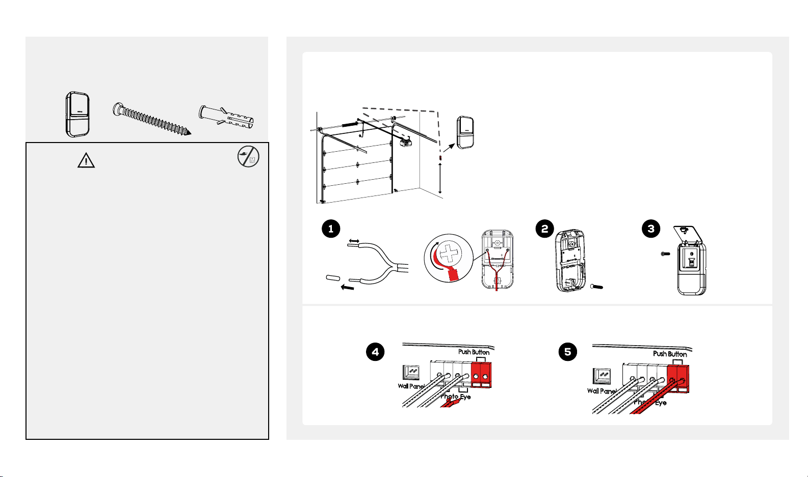
CONNECTING STANDARD DOOR CONTROL (BU100)
Look in the box for:
Standard Door
Control
2 x Lag Screws
#6 x 1-3/8"
2 x Anchors
WARNING
To prevent SERIOUS INJURY or DEATH from electrocution or
fire:
• Be sure power is NOT connected BEFORE installing door
control.
• Connect door control ONLY to 12 VOLT low voltage wires.
To prevent SERIOUS INJURY or DEATH from a closing garage
door:
• Install door control within sight of garage door, at a
minimum height of 5 feet (1.5 m) so small children are not
able to reach it, and away from ALL moving parts of door.
• NEVER permit children to operate or play with door
control or remote controls.
• Activate garage door opener ONLY when door can
be seen clearly, is properly adjusted, and there are no
obstructions to door travel.
• ALWAYS keep a moving garage door in sight until
completely closed. NEVER cross path of moving garage
door.
Wire standard door control to
opener as shown.
Standard Door
Control
2. Connect one wire to each of the two screws on the back of the
door control. *DO NOT RECOMMEND USING PRE-EXISTING
WIRE*
3. Mark the location of bottom mounting hole and drill 5/32 inch hole.
4 Install the bottom screw and allow 1/8 inch (3 mm) to protrude
from wall. Note: Use anchors if mounting to drywall.
5. Position bottom hole of door control over the screw and slide
1. Strip 7/16 inch (11 mm) of insulation from wire and separate wires.
Min. 5 feet
(1.52 m)
above floor
down into place.
6. Li actuation button and mark the top hole. Remove the door
control from wall and drill 5/32 inch hole for top screw.
7. Position bottom hole of door control over the screw and slide
down into place. Fasten the top screw.
1/4" (6mm)
Top screw
Bottom screw
Connect the wire from the standard door control to the push button terminal on the rear panel of the power head.
*NOTE: Your opener will contain one of two door controls. Follow the instructions corresponding to the control provided.
beamlabs.io 1-800-436-9186 21
Page 24
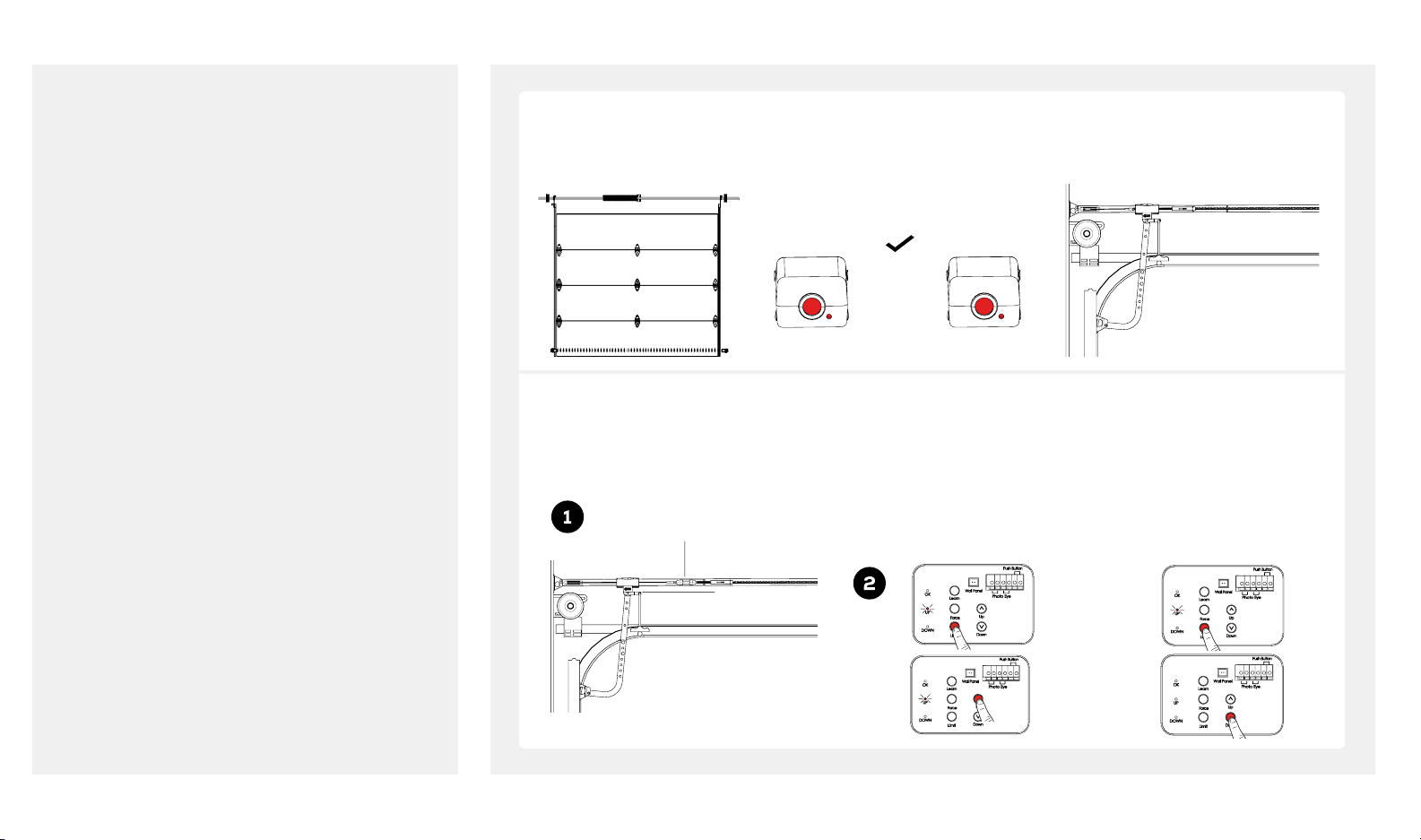
BEFORE WE START PROGRAMMING THE OPENER
Before programming the garage door opener please ensure the following steps are completed:
Door is fully closed. Photo eyes are aligned. Trolley sha is engaged with trolley.
Emitter
Green LED ON
Aligned
Steady Red &
Green LED
To engage trolley sha with trolley.
Flip lever on trolley so it is in engage
position (horizontal and pointing at
the opener)
If trolley sha is closer to the opener
(behind the trolley): press and
release “Limit” button and then
press and hold the red “DOWN”
button to move trolley sha towards
the door. There will be an audible
click once the trolley sha is
Trolley Sha
Trolley in engaged
position
engaged with trolley.
Sensor
Red LED ON
If trolley sha is closer to the
door (in front of the trolley): press
and release “Limit” button and
then press and hold the green
“UP” button to move trolley sha
towards the opener. There will be
an audible click once the trolley
sha is engaged with trolley.
22 beamlabs.io 1-800-436-9186
Page 25
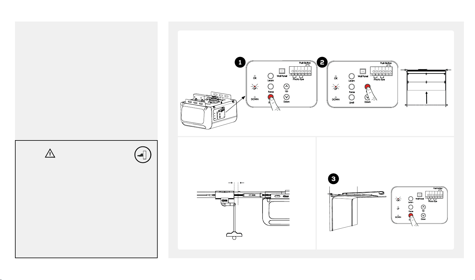
TRAVEL LIMIT ADJUSTMENT - UP LIMIT
NOTICE:
Travel limits and auto force setting must be set for
the opener to work. All steps on pages 23-25 must
be followed.
Press and release “Limit” button, the green (UP) LED will illuminate. Press and hold the “Up” button until door
reaches desired open position.
WARNING
To prevent SERIOUS INJURY or DEATH from
improper Force Adjustment:
• YOU CANNOT adjust force manually to compensate
for binding or sticking of the garage door. Call
a qualified garage door service person to make
necessary adjustments in case of binding.
• YOU CANNOT manually increase the force required
for closing the door.
• Aer ANY adjustments, Safety Reversal Test MUST
be performed to ensure the door reverses on contact
with a 1-1/2 inch (3.8 cm) high object (2x4 laid flat).
Press and release
LIMIT just once
* DO NOT HIT STOP BOLT *
There should be a minimum 2 inch (5 cm) gap
between trolley and stop bolt.
Minimum 2 inch (5 cm) gap
Stop Bolt Trolley
Press and hold UP
Once the door is at the desired open position,
press and release the “Limit” button once. The
“OK” LED flashes and turns off. The UP Limit has
now been set.
Desired
UP limit
Press and release LIMIT just once
beamlabs.io 1-800-436-9186 23
Page 26
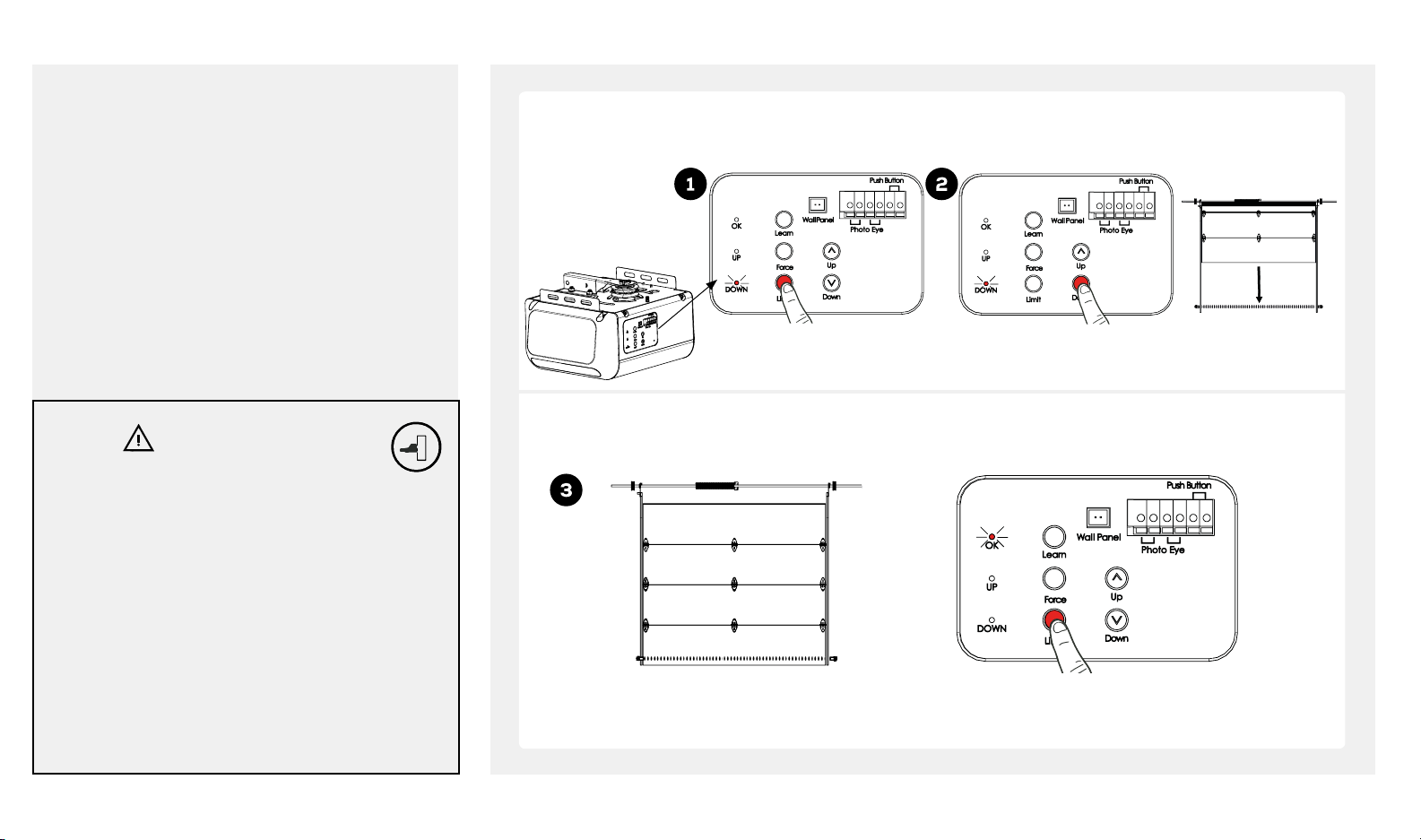
TRAVEL LIMIT ADJUSTMENT - DOWN LIMIT
NOTICE:
Travel limits and auto force setting must be set for
the opener to work. All steps on pages 23-25 must
be followed.
Press and release “Limit” button twice, the red (DOWN) LED will illuminate. Press and hold the “Down” button
until door reaches desired close position.
WARNING
To prevent SERIOUS INJURY or DEATH from
improper Force Adjustment:
• YOU CANNOT adjust force manually to compensate
for binding or sticking of the garage door. Call
a qualified garage door service person to make
necessary adjustments in case of binding.
• YOU CANNOT manually increase the force required
for closing the door.
• Aer ANY adjustments, Safety Reversal Test MUST
be performed to ensure the door reverses on
contact with a 1-1/2 inch (3.8 cm) high object (2x4
laid flat).
24 beamlabs.io 1-800-436-9186
Press and release
LIMIT twice
Once the door is at the desired close position, press and release the “Limit” button once. The “OK” LED flashes
and turns off. The DOWN Limit has now been set.
Desired DOWN limit
Press and hold DOWN
Press and release LIMIT just once
Page 27
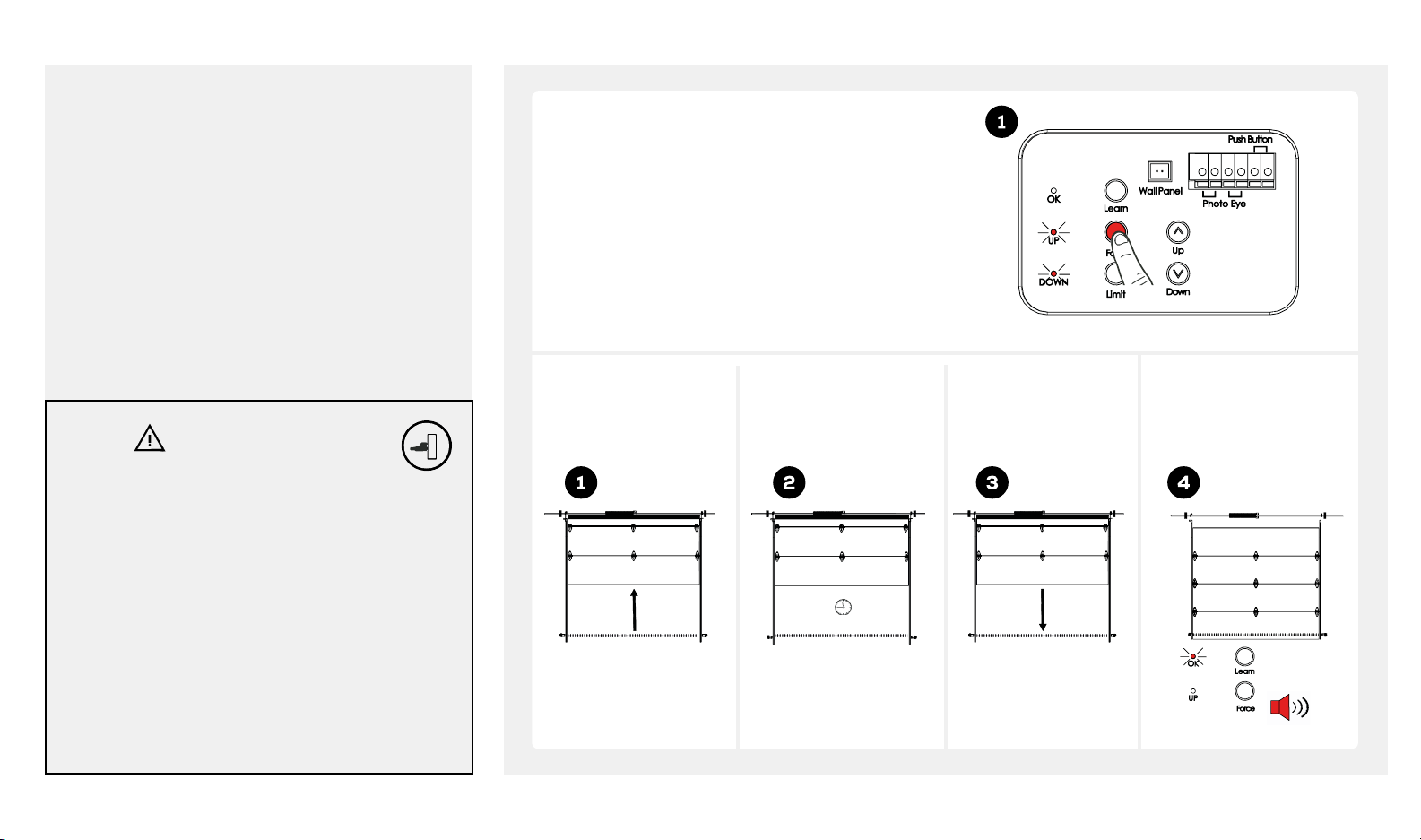
SETTING THE FORCE
NOTICE:
Travel limits and auto force setting must be set for
the opener to work. All steps on pages 23-25 must
be followed.
Once UP and DOWN limits are set, ensure both UP and
DOWN LEDs are illuminated. *if necessary toggle “Limit”
button until both LEDs are illuminated*
Press and release the “Force” button once. Door will travel
one complete cycle followed by flashing of the “OK” LED
and 3 beeps. Programming is now complete.
WARNING
To prevent SERIOUS INJURY or DEATH from
improper Force Adjustment:
• YOU CANNOT adjust force manually to compensate
for binding or sticking of the garage door. Call
a qualified garage door service person to make
necessary adjustments in case of binding.
• YOU CANNOT manually increase the force required
for closing the door.
• Aer ANY adjustments, Safety Reversal Test MUST
be performed to ensure the door reverses on
contact with a 1-1/2 inch (3.8 cm) high object (2x4
laid flat).
The door will travel
UP automatically.
Stop at UP limit for 2
seconds.
2 sec
Door will then
travel DOWN
automatically.
OK indicator (orange)
will flash with beeps,
Auto Force Setting is
completed.
Flash and 2
beeps
beamlabs.io 1-800-436-9186 25
Page 28
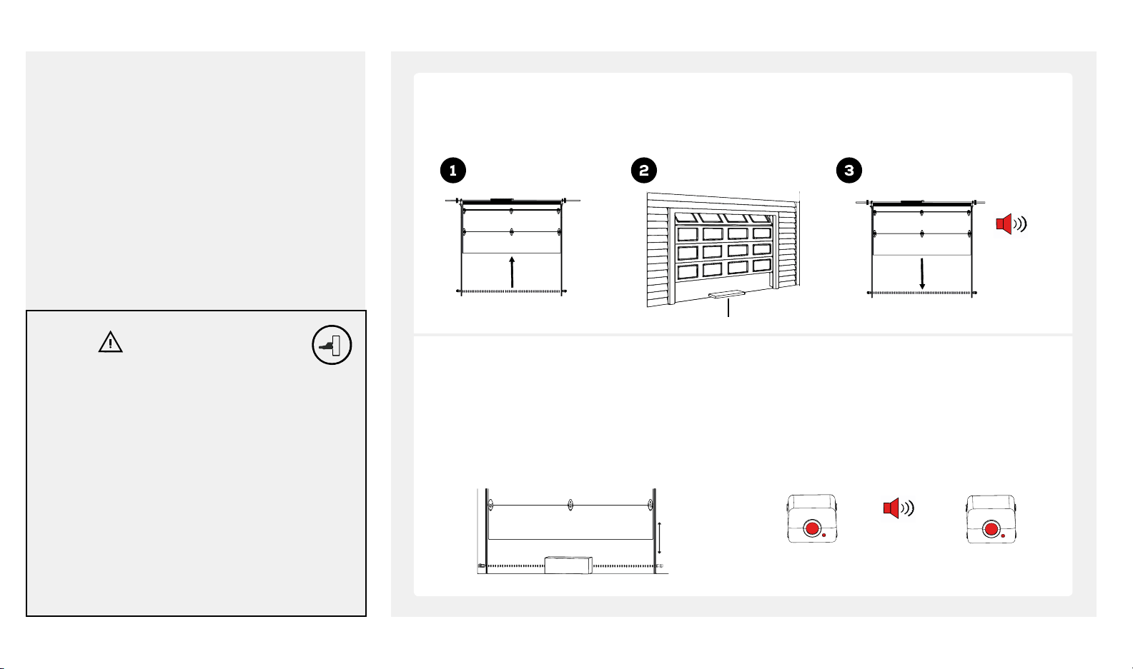
FINAL ADJUSTMENTS AND TESTING
NOTICE:
Travel limits and auto force setting must be set for
the opener to work. All steps on pages 23-25 must
be followed.
WARNING
To prevent SERIOUS INJURY or DEATH from a
closing garage door:
• The Safety Reversal Test MUST be conducted ONCE
A MONTH.
• NO ONE should cross the path of moving door
during operation and/or testing.
• Aer ANY adjustments to the door system, the
Safety Reversal Test MUST be performed to ensure
the door reverses on contact with a 1-1/2 inch
(3.8 cm) thick (2x4 laid flat) object.
• The Photo Eye Safety System MUST be properly
aligned, and tested regularly.
Test the Safety Reversal System
Open door using
door control.
Test the Photo Eye Safety System
1. Open door by using the door control.
2. Make sure photo eye safety system is aligned with
both the red and green LEDs illuminated. If not,
refer back to pages 17-18.
3. Place the garage door opener carton in the path of
the door.
Place a 1-1/2 inch (3.8cm)
flat solid object on the floor,
centered under the garage door.
1-1/2 inch (3.8 cm) solid object
Use door control or remote to close door.
Door MUST reverse* upon making contact
with the object.
beeps upon
contact
4. Keeping the door in sight press the door control
or remote control to close the door
Door should NOT move more than 1 inch (2.5 cm) and
the garage door opener will beep and flash 20 times.
Emitter Sensor
20 beeps and
Green LED
Flashes
reverses upon
obstruction
Red LED
OFF
26 beamlabs.io 1-800-436-9186
* If door does not reverse, return to page 21, reprogram the operator, taking care to set the down limit lower than initially.
Page 29
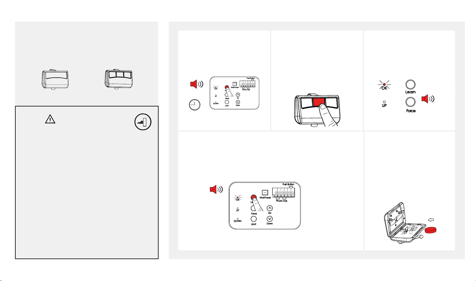
PROGRAMMING HANDHELD REMOTE CONTROL*
Look in the box for:
Single Button Remote
BU100
Three Button Remote
BU400 & BU800
WARNING
To prevent SERIOUS INJURY or DEATH:
• Keep remote control and battery out of reach of
children.
• NEVER permit children to access door control or
remote control.
• Operate the door ONLY when it is properly
adjusted, and there are no obstructions present.
• ALWAYS keep a moving door in sight until
completely closed. NEVER cross the path of a
moving door.
1. Press and release the “Learn”
button.
2. The “OK” LED will illuminate
indicating ready for
programming.
Beeps
30 sec
Erasing ALL remote controls from memory:
To erase ALL remote controls from memory, press and hold “Learn”
button for 3 seconds. “OK” LED will flash and beep three times
indicating all remotes have been erased from memory.
Press and release LEARN
Beeps
3. Press desired button on
remote control within 30
seconds to program.
*Additional buttons on remote
can be used to program
multiple beamUP garage door
openers*
Press and hold
LEARN 3 sec
The “OK” LED flashes twice
followed by two beeps to
confirm remote has been
programmed.
2 x flashes
2 x beeps
When battery of hand held
remote control is low, indicator
LED will become dim and/or
range of remote control will
decrease. To replace battery,
remove battery cover from
remote control. Replace with a
CR2032 3 volt battery.
To reduce risk of fire, explosion or electric shock:
• DO NOT short circuit, recharge, dissemble or heat
the battery.
• Replace with a CR2032 3 volt battery ONLY.
*NOTE: Your opener will contain one of two different remote controls. Follow the instructions corresponding to the remote control provided.
beamlabs.io 1-800-436-9186 27
Page 30
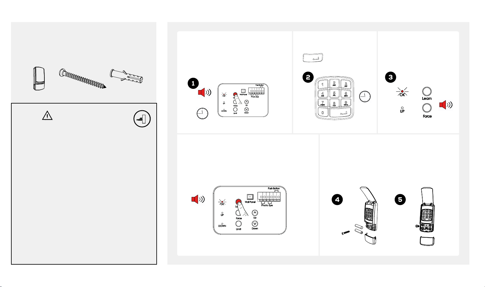
PROGRAMMING WIRELESS KEYPAD (BU800)
Look in the box for:
1. Press and release the “Learn” button.
Wireless
keypad*
2 x Lag Screws
#6 x 1-3/8"
2 x Anchors
2. The “OK” LED will illuminate
indicating ready for programming.
3. Garage door opener is ready to accept
PIN within the next 30 seconds.
Beeps
Enter your 2-6 digit PIN within
30 seconds and press the
ENTER button.
30 sec
"OK" LED will flash and beep
twice indicating code is set.
2 x flashes
2 x beeps
WARNING
To prevent SERIOUS INJURY or DEATH:
• Keep remote control and battery out of reach of
children.
• Never permit children to access the door control or
remote control.
• Operate door ONLY when it is adjusted properly with
no obstructions to door travel and is in clear sight.
• ALWAYS keep a moving door in sight until
completely closed. NO ONE should cross the path
of a moving door.
To reduce risk of fire, explosion or electric shock:
• DO NOT short circuit, recharge, disassemble or
heat battery.
• Replace with 2 x AAA batteries ONLY. Dispose of
batteries properly.
28 beamlabs.io 1-800-436-9186
*NOTE: If your model is provided with a Wireless Keypad, follow the programming instructions on this page.
30 sec
Erasing ALL remote controls from memory:
To erase ALL remote controls from memory, press
and hold “Learn” button for 3 seconds. “OK”
LED will flash and beep three times indicating all
remotes have been erased from memory.
2 x beeps
Press and release LEARN
Press and hold LEARN for 3 seconds
Wireless keypad may be secured on door jamb
outside your garage. Install keypad within sight
of door at minimum height of 5 feet (1.5 m). Test
the range of the keypad before mounting. Find an
alternative mounting location if range is insufficient.
Page 31
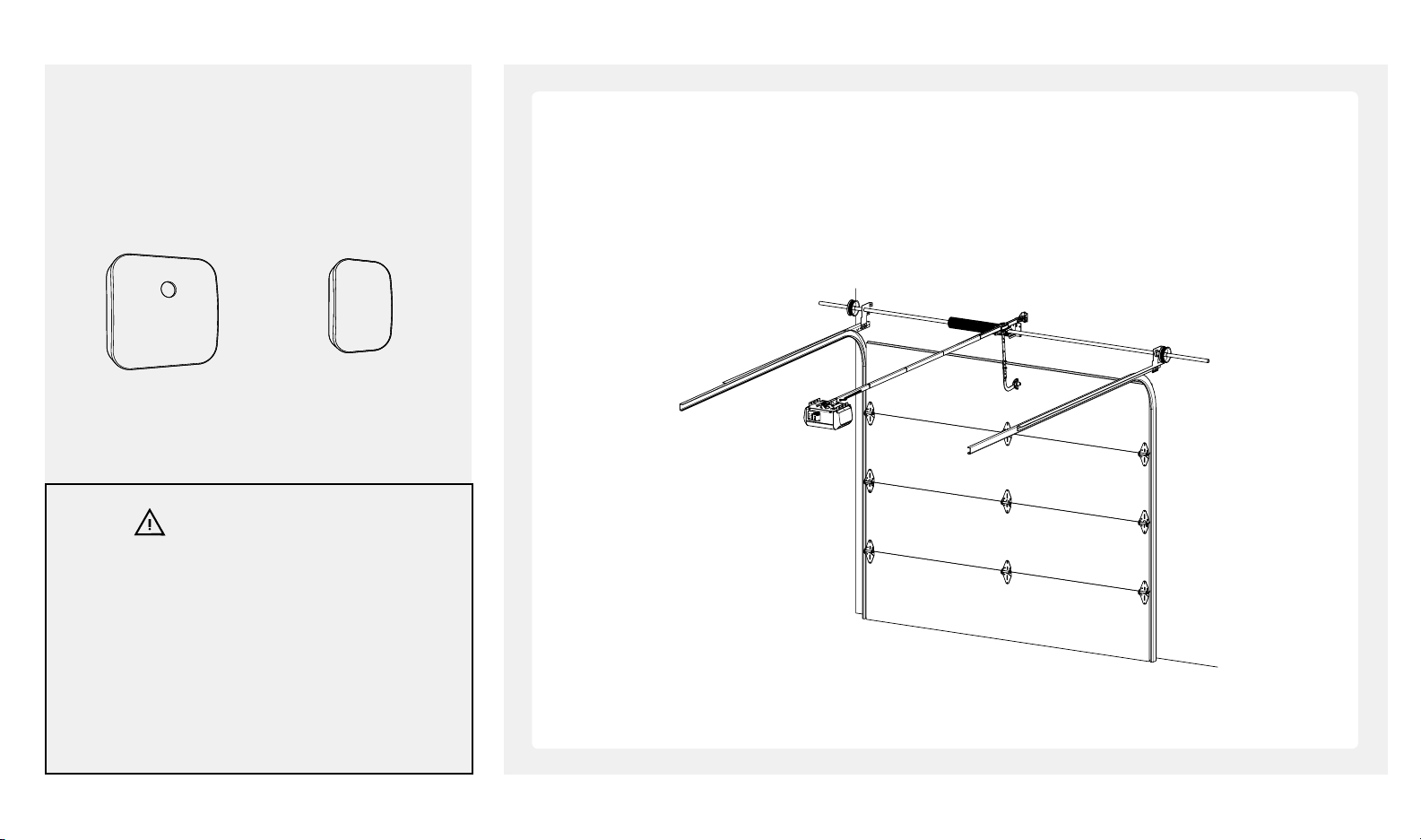
INSTALLING THE SMART GARAGE DOOR CONTROLLER (BU400, BU800)
Look in the box for:
Installation and programming of your beamUP garage door opener is now complete.
• Locate the beam Smart Garage Door Controller
• Follow instructions in the Smart Garage Door Controller installation guide to add smart phone control to your
beamUP garage door opener.
Controller Wireless Door Sensor
WARNING
To reduce the risk of injury to persons:
• Use this Smart Control Kit only with residential
sectional garage doors.
• Do not enable this device on a one-piece or
swinging garage door.
• Do not use this device on garage door openers
made before 1993 without a working photo eye
safety system.
beamlabs.io 1-800-436-9186 29
Page 32
USING YOUR GARAGE DOOR OPENER
WARNING
To prevent SERIOUS INJURY or DEATH:
• READ AND FOLLOW ALL INSTRUCTIONS AND
WARNINGS IN THE OWNER’S MANUAL AND
LABELS
• Keep remote control and batteries out of reach of
children.
• NEVER permit children to access door controls or
remote controls.
• Operate the door ONLY when it is properly
adjusted, and there are no obstructions and is in
clear sight.
• ALWAYS keep a moving door in sight until
completely closed. NEVER cross the path of a
moving door.
• Aer ANY adjustments, the Safety Reversal Test
MUST be performed to ensure the door reverses on
contact with a 1-1/2 inch (3.8 cm) thick object (2x4
laid flat).
• ALWAYS ensure that your door is balanced and in
good working condition.
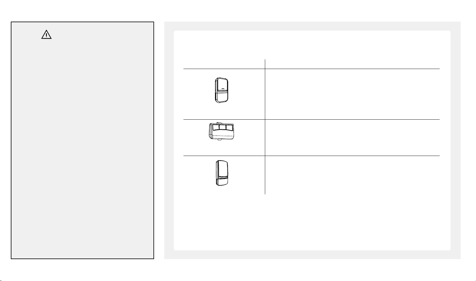
Activating the Opener
Controls Operation
Remote distance up to 100 feet in open field. For safety concerns, the
handheld remote control WILL NOT work if the photo eye safety system is
Program the wireless keypad accordingly and access the door using the
Momentary press large “ACTUATOR” button on the door control, the door
starts to move, and controls as follows:
• Open or close the door.
Door Control
Handheld Remote
Control
Wireless Keypad
• Stops the door while closing
• Stops the door while it is opening.
not properly installed and aligned or if vacation lock is activated.
PIN code.
30 beamlabs.io 1-800-436-9186
Page 33
USING YOUR GARAGE DOOR OPENER
WARNING
To prevent SERIOUS INJURY or DEATH:
• Use emergency release to disconnect trolley
ONLY when the door is CLOSED to prevent
unexpected rapid falling in case of a unbalanced /
poor-conditioned door.
• Use emergency release ONLY when doorway is
clear of persons and obstructions.
• DO NOT use emergency release to pull the door
open or closed.
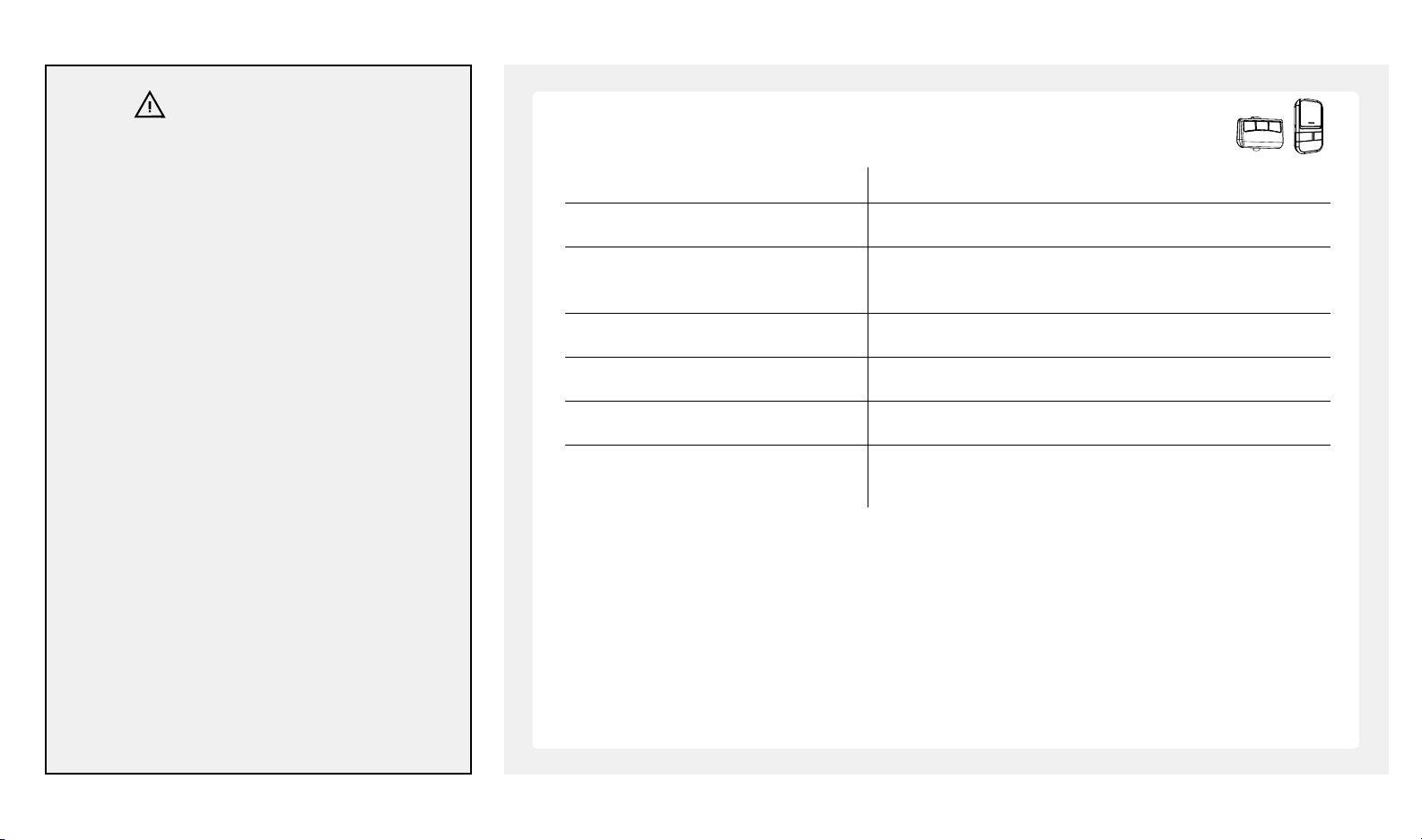
Door Status vs. Activation
Door Status Activation Using Door Control / Remote Control
Door at fully open / close position Door will move to fully close / open position
Door is closing Door will stop. Upon next activation door will reverse to fully
Door is opening Door will stop. Upon next activation door will continue to open.
Door is obstructed while closing Door will reverse and beep x 25
Door is obstructed while opening Door will stop and beep x 25
Door is fully opened and photo eye Door will not close and beep x 20
safety system is obstructed
open position.
beamlabs.io 1-800-436-9186 31
Page 34
USING YOUR GARAGE DOOR OPENER
WARNING
To prevent SERIOUS INJURY or DEATH:
• Use emergency release to disconnect trolley
ONLY when the door is CLOSED to prevent
unexpected rapid falling in case of a unbalanced /
poor-conditioned door.
• Use emergency release ONLY when doorway is
clear of persons and obstructions.
• DO NOT use emergency release to pull the door
open or closed.
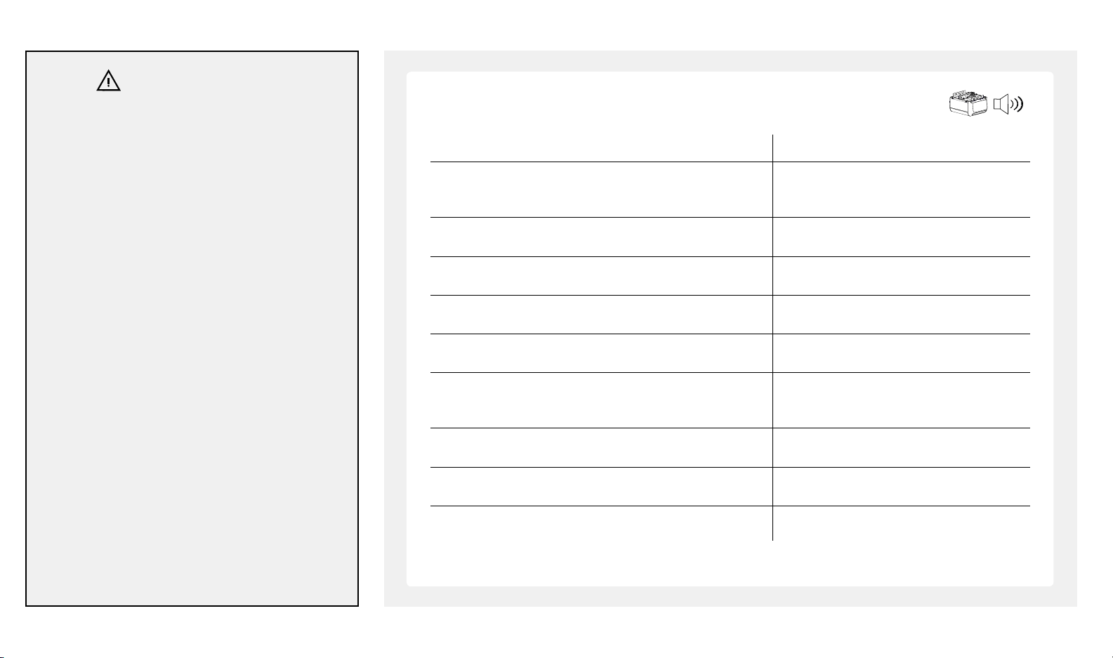
Courtesy Light / Buzzer Responses
Operation / Condition Courtesy Light / Buzzer Responses
Opener is initially plugged-in (no travel limits stored UP and DOWN indicators blink 5 times
see pages 23-25):
Reconnecting power (with travel limits stored) Light On for 4.5 minutes
“LEARN” button is pressed Beep x 1, OK indicator glows
Upon activation Light on for 4.5 minutes
Upon activation by remote controls Beep x 1, Light on for 4.5 minutes
Remote control / keyless entry PIN Beep x 2
code stored successfully
32 beamlabs.io 1-800-436-9186
Photo eye safety system is obstructed during door-closing Beep x 20
The door is obstructed during travel Beep x 25
Door travels with abnormal speed Beep x 12 (1 beep / second)
Page 35
USING YOUR GARAGE DOOR OPENER
Manual Operation
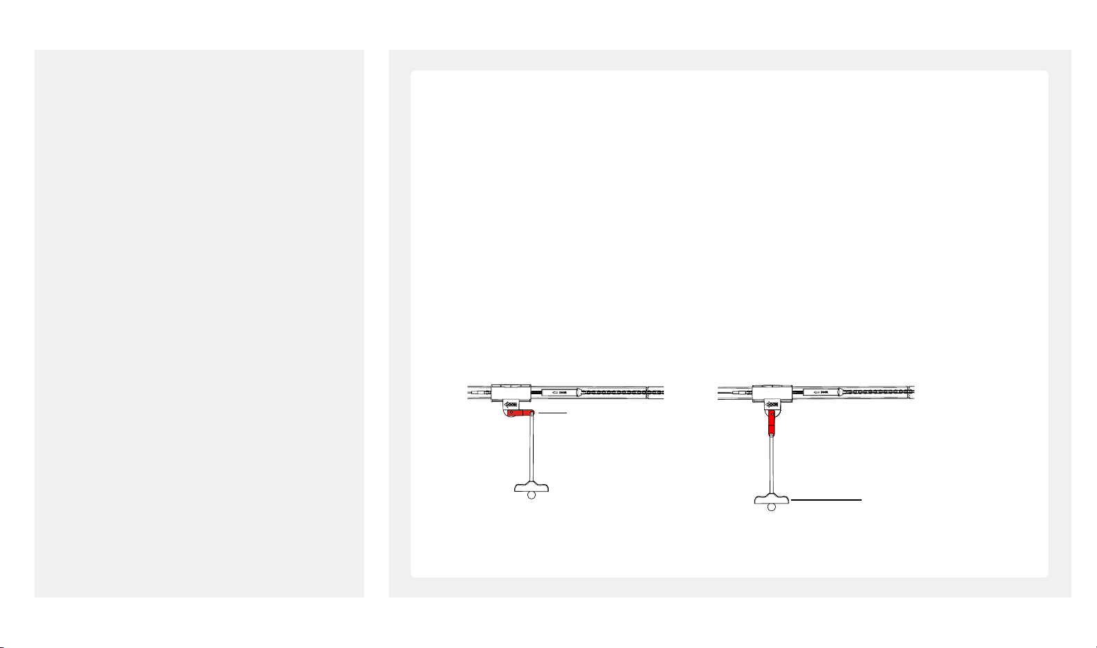
In case of a power failure or door obstruction, PULL EMERGENCY HANDLE to release door from opener.
To Disengage Trolley for Manual Operation
With door closed, pull down emergency handle to disengage position. Door can be raised / lowered manually.
To Engage Trolley
Pull the handle toward opener so that lever will flip up to engage position. Trolley will reconnect itself when
opener is activated or when the door is manually opened /closed.
Engage:
Pull to disengage
Disengage:
Flip to engage
Lever
Emergency Release Handle
beamlabs.io 1-800-436-9186 33
Page 36
USING YOUR GARAGE DOOR OPENER
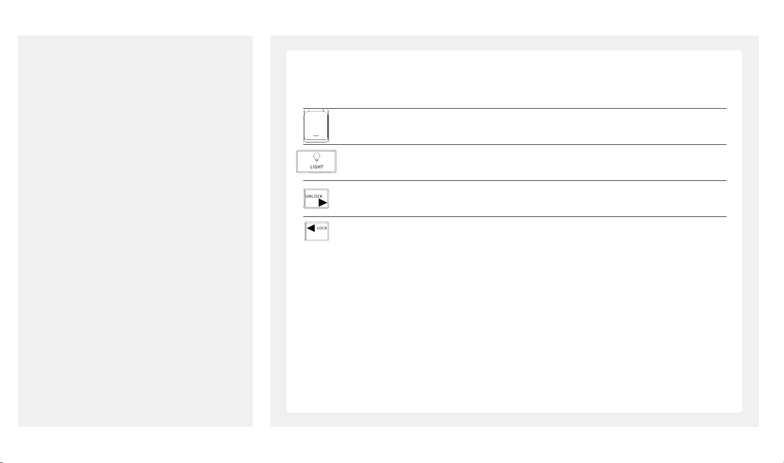
Using the Deluxe Door Control
(ONLY aer programming has been completed)
Door – Press and release to open/close the door
Light – Turns the courtesy light on/off
Press and hold to activate/deactivate motion sensing security lighting
Vacation Lock
Unlock – Slide lock button to the right to enable all remotes, door control and accessories.
Lock – Slide lock button to the le to disable all remotes, door control and accessories.
34 beamlabs.io 1-800-436-9186
Page 37
TROUBLESHOOTING
NOTICE
Opener will not work until you set the travel limits
and the auto force adjustment. You must follow all
steps located on pages 23-25.
So open / So close feature: opener is designed
to start slowly, accelerate to full speed, then slowly
stop. So open/close is designed to reduce strain
on openers components and to improve opener
longevity.
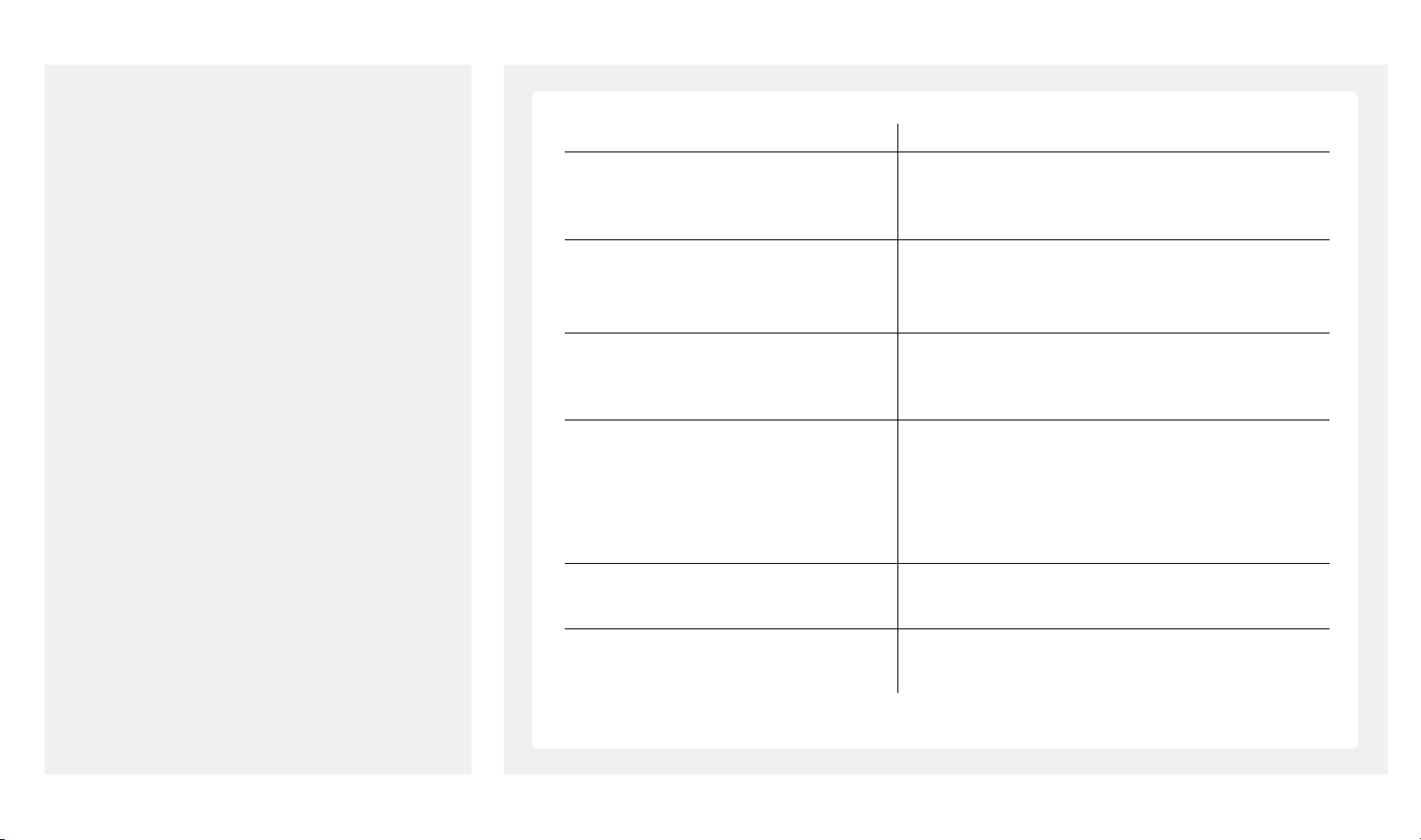
Problem Possible Cause / Solution
Opener does not close and beeps x 20 The photo eye may be obstructed, not properly aligned or
installed, check connection and alignment by referring to
page 17.
Opener does not respond to • Refer to page 27 to reprogram remote control.
remote control
Opener stops before reaching full Travel Limit is not properly set, check adjustment
open / close position referring to pages 23-25. Conduct safety reverse test aer
Door reverses unintentionally • Make sure the photo eye safety system is aligned
Door reverses and courtesy light flashes Refer to pages 23-25 to reset travel limits and force
• Check remote control battery and vacation switch if
deluxe door control is installed.
ANY adjustment.
and clear of obstructions.
• Refer to page 3 to check the door balance
• Refer to pages 23-25 to reset travel limits and force
adjustment.
adjustment.
Opener does not close the door and
LED on one of photo eyes flashes obstructed, refer to page 17-18 for proper alignment.
The photo eye safety system is misaligned or
beamlabs.io 1-800-436-9186 35
Page 38
TROUBLESHOOTING
Problem Possible Cause / Solution
Opener is working properly but Replace LED cluster.
courtesy light does not turn on
Courtesy light does not turn off Replace logic board.
Opener hums as trolley hits the 1. Disconnect trolley by using the emergency release.
trolley stop
2. Close door manually.
3. Relieve chain-to-cable connector by loosening both,
refer to page 8.
4. Operate opener so trolley sha travels towards door
(trolley should be kept disengaged).
5. Refer to page 23 to reset UP Limit.
6. Refer to page 8 to re-tighten chain-to-cable connector
until it is 1/4 inches (.64 cm) above the base of rail
(reference the figure shown on page 8).
7.
Repeat the above steps if trolley still hits the stop bolt.
36 beamlabs.io 1-800-436-9186
Page 39
MAINTENANCE
Schedule Maintenance
Once a month Door balance test, refer to page 3.
Twice a year Safety reversal test, refer to page 26.
Once a year Check cable/chain tension (refer to page 8 for
adjustment if necessary).
• Limit and Force adjustment may be necessary due to
weather conditions. Refer to pages 23-25 for adjustment.
Conduct Safety Reversal Test aer ANY adjustments.
• Lubricate door rollers, bearings and hinges. The opener
is permanently lubricated, DO NOT lubricate or grease
the opener, rail or door tracks.
beamlabs.io 1-800-436-9186 37
Page 40

WARRANTY
Manufacturer hereby warrants to the original purchaser, for initial residence in which it
is installed:
1. Garage Door Operators to be free from defects in material and workmanship for
a period of one (1) year from date of purchase. The model BU100 motor is to be free
from defects in materials and workmanship for 5-years from the date of purchase.
The models BU400 and BU800 motor is to be free from defects in materials and
workmanship for the lifetime of the product.
2. Where the garage door operator has need to be returned to the Manufacturer for
Warranty repairs, all costs incurred in the return will be paid for by the purchaser. Call
1-800-436-9186 prior to dismantling the product. If in the opinion of the Manufacturer
the product is faulty, all defective parts will be replaced at no charge to the purchaser.
3. Proof of purchase must be given to the Manufacturer at time of Warranty claim.
4. The Manufacturer reserves the right to modify any existing or future products
without incurring any obligation to incorporate such modification to products already
manufactured or to which this Warranty may relate.
5. Warranty only applies if this product has been installed to the Manufacturer's
instructions.
6. This Warranty does not apply to any defect, loss or damage arising or caused
directly or indirectly by or as a result of :
(i) Any defect (including detects in component parts or accessories) arising from or
attributable to the failure to carry out normal preventive maintenance or adjustment
itself.
of the Operator aer it is known to be defective.
7. Not included in Warranty:
(i) Batteries
(ii) Fuses
(iii) Sensitivity adjustment
(iv) Handheld Remote Controls and receiver range
8. Note : All Warranties will be void subject to:
(i) Water damage and condensation
(ii) Power supply black out or surge
(iii) Act of God
(iv) Modification or adjustment by unauthorized persons
(v) Any interference from radio (including citizen band radios or and other electronic
device)
(vi) Preventative maintenance and regular servicing not undertaken
(vii) Account not paid in full by the purchaser
(ii) To any additional damage or deterioration arising from attributable to the operation
38 beamlabs.io 1-800-436-9186
Page 41

WARRANTY
9. Subject only to the provisions of the Trade Practices Act and any legislation of the
State or Territory wherein the operators of the Manufacturer have been sold or installed
(which may confer certain rights on consumers of goods and those rights by such
legislation may be rendered incapable of exclusion) this Warranty supersedes and
excludes all representations, warranties and conditions whether expressed or implied
by law and the Manufacturer shall have no liability or otherwise than herein provided
for any loss and damage (including consequential loss and damage, loss of use or
profits) by reasons of delay, defective or faulty materials or workmanship, negligence
or any act, matter or thing done permitted or omitted to be done by the Manufacturer.
Warranty
THIS WARRANTY FORM SHOULD BE COMPLETED AT TIME OF INSTALLATION
This Warranty Form should be retained by the purchaser at all times and produced
with the purchase docket by the
Purchaser as proof of the purchase date ___________________________________
PURCHASER’S NAME:_______________________________________________
PURCHASER’S ADDRESS:____________________________________________
INSTALLED BY:____________________________________________________
SERIAL NUMBER OF THE OPERATOR: __________________________________
beamUP Service
Owners are encouraged to register their product on www.beamlabs.io
Helpuful product and troubleshooting information may be found online at
www.beamlabs.io
Service number : 1-800-436-9186
Please have the following information when you call:
• Model number of the operator
• Serial number of the operator
beamlabs.io 1-800-436-9186 39
Page 42

WARRANTY
Por la presente, el fabricante garantiza que al primer comprador (usuario) de este
producto, en uso de la residencia en que fuera originalmente instalado:
1. Los operadores de la puerta de garaje responden por defectos de material y mano
de obra por un periodo de un (1) año de la fecha de compra. El motor del modelo
BU100 responde por defectos de material y mano de obra por un periodo de cinco (5)
años de la fecha de compra. El motor de los modelos BU400 y BU800 responden por
defectos de material y mano de obra por el total de vida del producto.
2. En el momento del reclamo de garantía, se debe entregar al fabricante la prueba de
compra. Llama al 1-800-436-9186 antes de desmontar el producto.
3. El fabricante se reserva el derecho de modificar cualquier producto existente
o futuro, sin incurrir en ninguna obligación de incorporar tal modificación a los
productos que ya están fabricados o a los que pueda referir esta garantía.
4. La garantía sólo aplica si el producto ha sido instalado bajo las instrucciones del
fabricante.
5. Esta garantía no aplica a ningún defecto, pérdida o daño derivados o causados de
manera directa o indirecta por o como resultado de:
(i) Cualquier defecto (incluyendo los defectos en las partes componentes o accesorias)
que surja de, o que sea atribuible a, la falta de la ejecución del mantenimiento
preventivo normal o del ajuste del mismo.
(ii) Cualquier daño adicional o el deterioro que surja atribuible al hecho de que el
operador la hace funcionar después de que se sabe que está defectuosa.
6. No están incluidos en la garantía:
(i) Pilas
(ii) Fusibles
(iii) Ajustes de sensibilidad
(iv) Los controles remotos manuales y el alcance del receptor
7. Tenga en cuenta que: todas las garantías estarán sujetas a:
(i) Los daños por agua y la condensación
(ii) El apagón del suministro de energía o sobretensión
(iii) Los desastres naturales
(iv) Las modificaciones y ajustes realizados por personas no autorizadas
(v) Cualquier interferencia de radio (incluyendo las radios de banda ciudadanas u otro
dispositivo electrónico)
(vi) El no emprendimiento del mantenimiento preventivo y el servicio de
mantenimiento regular
(vii) La cuenta no pagada en su totalidad por parte del comprador.
8. Sujeta únicamente a las disposiciones de la Ley de prácticas comerciales y de
cualquier legislación del estado o territorio en el que los operadores del fabricante
han sido vendidos o instalados (que pueden conferir ciertos derechos para los
consumidores de bienes y esos derechos, por dicha legislación, pueden traducirse
como imposibles de exclusión) esta garantía reemplaza y excluye todas las
representaciones, garantías y condiciones ya sea expresas o implícitas por la ley y el
fabricante no tendrá responsabilidad o de otro tipo distinto al que se ha establecido
aquí por cualquier pérdida o daño (incluyendo pérdidas o daños consecuenciales,
40 beamlabs.io 1-800-436-9186
Page 43

WARRANTY
pérdidas por el uso o ganancias) por razones de retraso, materiales o mano de obra
defectuosos o en falta, negligencia o cualquier acto, hecho o cosa realizada que el
fabricante permitida u omitida que se haga.
GARANTÍA
ESTE FORMULARIO DE GARANTÍA DEBE LLENARSE EN EL MOMENTO DE LA
INSTALACIÓN.
Este formulario de garantía lo debe conservar el comprador todo el tiempo y producir
con la factura de compra el comprador como prueba de la fecha de compra.
NOMBRE DEL COMPRADOR:___________________________________________
DIRECCIÓN DEL COMPRADOR:_________________________________________
INSTALADO POR:___________________________________________________
NÚMERO DE SERIE DEL OPERADOR: _____________________________________
SERVICIO
Se recomienda a los propietarios que registren su producto en www.beamlabs.io.
Ayuda e información sobre solución de problemas del producto se pueden encontrar
en línea en www.beamlabs.io
Teléfono de Servicio 1-800-436-9186
Debe tener la siguiente información al momento de realizar la llamada:
• Número de modelo del operador
• Número de serie del operador
beamlabs.io 1-800-436-9186 41
Page 44
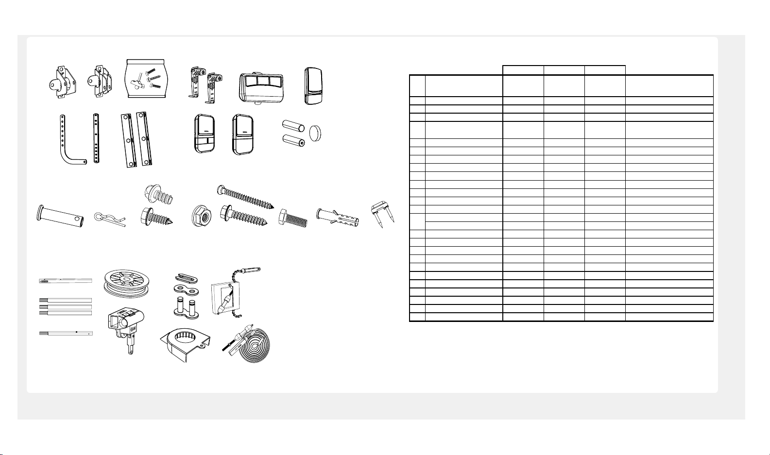
SPARE PARTS
BU100 BU400 BU800
# Nam e/Descriptio n
Part #
No. de part e
Part #
No. de part e
Part #
No. de part e
Nom bre/Descripci ón
INSTALLATION PARTS PARTES DE I NSTALA CION
1 Hea der Brac ket RP-007 RP-007 RP-007 Sopor te Cabec ero
2 Door Bracket GUAT-022 GUAT-022 GUAT-022 Sopo rte de la Puerta
3
Ha rdware Ba g/Emergenc y Releas e
Ha ndle
RP-008 RP-008 RP-008
Bolsa de Instalación/Manija de
Desc onexión de Em ergencia & Cuerda
4 Curved Door Arm GUAT-024 GUAT-024 GUAT-024 Brazo curvo de la Puerta
5 Straigh t Door Arm GUAT-025 GUAT-025 GUAT-025 Br azo rec to de la Puerta
6 Hangi ng Bra cke t RP-009 RP-009 RP-009 Soportes Estructurales
ACC ESSORIES ACC ESORIOS
7 Photo Eye Safet y Syst em GUAT- 201 GUAT- 201 GUAT-201
Sist ema de Seguri dad de Senso r ópti co
8 Handh eld Tras mitt er R1BU R3BU R3BU Transmisor Manual
9 Wireles s Keypa d KPDBU Teclado Inalámbrico
10 Deluxe Door Control 3FBU 3FBU C ontro l de Puerta d e Lujo
11 Standard Door Control 1FBU Control de Puerta Estándar
a. Wireles s Keypa d Batt ery AAA a. Batería Teclado Inalámbrico
b. Remote Control Battery CR2032 3V CR2032 3V CR2032 3V b. Bater ía del C ontro l Remot o
RAIL ASSEMBLY PARTS ENSAM BLE DEL RIEL
13 Rail -Hea der Segment RP-001 RP-001 RP-001 Riel -Segment o de Cab ecera
14 Rail -Midd le Segment RP-002 RP-002 RP-002 Riel -Segment o del Medi o
15 Rai l-End Segment RP-003 RP-003 RP-003 Riel- Segmento Final
16 Pulley GUT-840 GUT-840 GUT-840 Po lea
17 Mast er Link Set GUT- 410 GUT- 410 GUT- 410 Conj unto de Enlac e Pri ncipa l
18 Trolley RP-004 RP-004 RP-004 Carro
19 Sproc ket Co ver RP-0 13 RP- 013 RP- 013 C ubierta de la Rueda Dent ada
20 Chain RP-006 RP-006 Cadena/C onect or
21 Trolley Shaft & Cable/Trolley Shaft RP-005 RP-005 RP-021 Eje del Carro & Cable/Ej e del Car ro
22 Belt RP-0 14 Correa
12
1
4
2 3
5 6
7
10
8
11
12
Clevis Pin Hitch Pin Self-Threading Flange Lag Screws Bolt Anchor Insulated
Screws Nut Staples
*NOTE: Not Available as individual parts
13 16 17
20
14
18
15
19
21
21
22
42 beamlabs.io 1-800-436-9186
9
a
b
Page 45
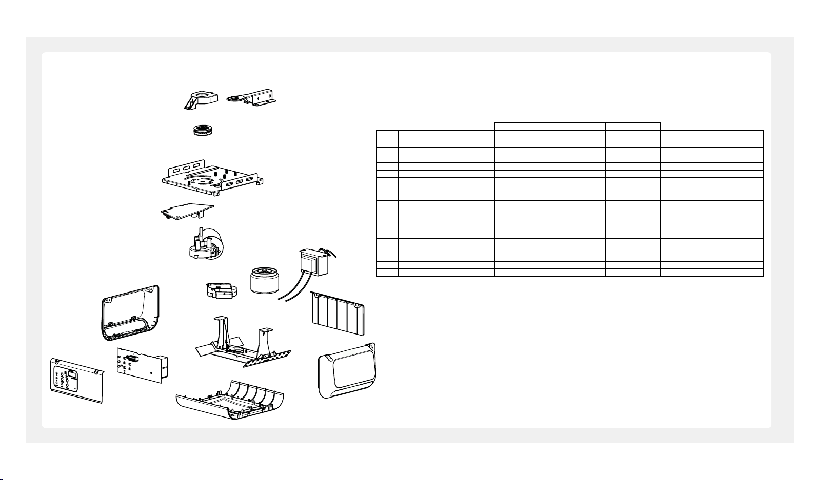
OPENER ASSEMBLY PARTS
BU100 BU400 BU800
# Name/D escriptio n
Part #
No. de par te
Part #
No. de par te
Part #
No. de par te
Nombre/D escri pción
INSTALLATION PARTS PART ES DE INSTALACION
1 Sprock et/Belt Pulley Co ver R P-013 RP-0 13 R P-013 Cu bierta de la R ueda Den tada
2 Rail Bracket RP-018 R P-018 R P-018 Soporte del Riel
3 Spr ocket/Pu lley RP-0 19 R P-019 R P-034 R ueda Dentada
4 Ch assis N/A N/A N/A Ch asis
5 Pow er Modu le LED R P-349 RP-350 RP-350 Módulo de Potencia LED
6 Motor GUDT -313 GUDT -313 GUDT-305 Motor
7 Side Panels RP-346 RP-347 RP-347 Paneles Later ales
8 Position Encoder GUDT -314 GUDT -314 GUDT -314 Codific ador de Posició n
9 Tr ansformers (9.1/9.2) GU DT-315 GU DT-315 GUD T-302 Tran sformadores (8.1/8.2)
10 Cover Plate - Front RP-341 R P-341 RP-341 Plac a de Cubierta - Frente
11 Co ver Plate - Ba ck R P-342 R P-342 RP-342 Placa de Cubierta - Trasero
12 Logic Bo ard R P-343 RP-343 RP-343 Receptor/Tablero Lógico
13 LED Clu ster LED
13.1 LED Clu ster, Cen ter RP-344 RP-344 RP-344 LED, Centra l
13.2 LED Cluster, Side ( 2) RP-348 RP-348 LED, Lateral (2)
14 Lamp D ome R P-345 RP-345 RP-345 Cúpula de Lampara
1
3
4
5
6
7
11
11
12
14
2
9.2
9.1
8
10
13
7
beamlabs.io 1-800-436-9186 43
 Loading...