

Page 1
USER MANUAL FOR BEAMEX MC6 WORKSTATION,
ADVANCED PANEL MOUNTED CALIBRATOR AND COMMUNICATOR
Applies to firmware version 3.10
Dear user,
We have made every effort to ensure the accuracy of the contents of this man-
ual. Should any errors be detected, we would greatly appreciate to receive suggestions to improve the quality of the contents of this manual.
For more detailed technical data about Beamex MC6 Workstation, please contact the manufacturer.
8860500 / MC6WSuEng / Version 3.1
© Beamex 2015 - 2018
BEAMEX OY AB
Ristisuonraitti 10
FIN-68600 Pietarsaari
FINLAND
Tel +358 - 10 – 5505000
Fax +358 - 10 – 5505404
E-mail: sales@beamex.com
service@beamex.com
Internet: https://www.beamex.com
Page 2

Page 3

MC6 Workstation, User Manual - Contents i
CONTENTS
Part 1, Introduction
General 2
About This Manual .................................................................. 2
Where Am I? .................................................................... 2
Typographical Conventions ............................................. 3
Unpacking and Inspection ...................................................... 3
About MC6 Workstation 4
Starting MC6 Workstation ....................................................... 4
Firmware ................................................................................ 5
Hardware ................................................................................ 7
General ............................................................................ 7
Pressure Modules ............................................................ 8
Front Panel Connection Details ....................................... 9
Connectors at the Back of MC6 Workstation .................... 9
Memory ......................................................................... 10
Display ........................................................................... 10
Batteries ........................................................................ 11
PC Communication / Calibration Software ............................ 12
USB Communication Driver ........................................... 12
MC6 Workstation Related Tools Available for PC .......... 12
Options 13
Software Options .................................................................. 13
Hardware Modules/Options and Accessories ....................... 14
Related Products .................................................................. 14
Part 2, Active Terminals and Connections
General 16
Measurements 17
Pressure Measurement ........................................................ 17
Connecting and Disconnecting External Pressure
Modules ........................................................................ 17
Zeroing a Pressure Module ........................................... 17
Current Measurement .......................................................... 18
Voltage Measurement .......................................................... 18
Temperature Measurement (Thermocouple) ........................ 19
Temperature Measurement (RTD) ....................................... 19
Resistance Measurement .................................................... 20
Frequency Measurement ..................................................... 20
Pulse Counting..................................................................... 21
Switch Sensing .................................................................... 21
Generations/Simulations 22
Changing the Generated/Simulated Value ........................... 22
Using the Soft Numeric Keypad .................................... 22
Spinning ........................................................................ 23
Current Generation (Source or Sink) .................................... 24
Voltage Generation .............................................................. 24
Thermocouple Simulation .................................................... 25
RTD Sensor Simulation ........................................................ 25
Resistance Simulation .......................................................... 26
Frequency Generation ......................................................... 26
Pulse Generation ................................................................. 27
Thermocouple Connections 28
Part 3, Meter
About Meter 30
Page 4

ii MC6 Workstation, User Manual - Contents
Part 4, Calibrator
About Calibrator 32
Tools 33
General ................................................................................ 33
Part 5, Documenting Calibrator
General 36
Calibration Software ............................................................. 36
Calibrating Instruments 37
Generating/Simulating the Input Value .......................... 37
Instrument List ..................................................................... 38
Instruments ................................................................... 38
Plant Structure Levels ................................................... 39
Instrument List Window Menu ....................................... 39
Instrument Overview Window ............................................... 40
Calibrating an Instrument Using MC6 Workstation ............... 40
Changing the Pressure Module During Calibration ........ 42
About Fieldbus and HART Device Specifics .................. 43
Group Calibration 44
Collecting Instruments/Functions for Group Calibration ........ 44
Editing a Group ............................................................. 45
Calibrating a Group .............................................................. 45
Group Settings .............................................................. 46
Performing the Calibration ............................................. 46
Calibration Results 47
Deleting Calibration Results ................................................. 47
Digital Communication and MC6 Workstation 48
Getting and Editing Mapped Data ........................................ 48
Preparations .................................................................. 48
Getting Default Mappings .............................................. 49
Customizing the Mappings ............................................ 49
Part 6, Data Logger
General 52
Doing a Data Log 53
Configuring ........................................................................... 53
Saving and Opening Configurations .............................. 53
Starting the Data Log ............................................................ 54
Viewing and Saving or Deleting the Results ......................... 55
Viewing Saved Data Log Results .......................................... 55
Transferring Data Log Results to a Personal
Computer ............................................................................. 56
Part 7, Communicator
General 58
Warnings .............................................................................. 59
Connections 60
Selecting the Instrument 61
List of Found Devices ........................................................... 61
About Instrument Parameters 62
Instrument Parameters in General ........................................ 62
Calibrating or Data Logging HART instruments .................... 63
Calibrating or Data Logging Fieldbus Instruments ................ 63
Editing Parameters ............................................................... 64
Trimming a Fieldbus instrument ............................................ 65
Trimming a HART instrument ............................................... 66
HART Device Description Specifics 67
General ................................................................................ 67
Basic View ..................................................................... 68
Page 5

MC6 Workstation, User Manual - Contents iii
Managing Smart Transmitter Configurations 69
General ................................................................................ 69
Tools in MC6 workstation ..................................................... 69
Saving Configurations .................................................... 69
Viewing/Managing Configurations .................................. 70
Beamex MC6 Workstation Fieldbus Configuration
Viewer .................................................................................. 70
Uploading Configurations............................................... 70
Linking Configurations to CMX....................................... 70
Part 8, Settings
Settings 72
Optional Security Tool 73
General ................................................................................ 73
Applied Restrictrions ...................................................... 73
Supervisor Window ........................................................ 74
Part 9, Additional Information
Additional Information 76
User Defined Pressure Units ................................................ 77
User Defined PRT / RTD Sensors ........................................ 78
General .......................................................................... 78
Callendar van Dusen Formula for PRTs ........................ 79
ITS-90 PRT Sensor ....................................................... 79
Factor ............................................................................ 81
Check Sensor Conversion ............................................. 81
User Defined Transfer Functions .......................................... 82
User Defined Steps / Calibration Points ................................ 83
Controller Communication .................................................... 84
What Can be Done With Controller
Communication .............................................................. 84
Configuring Controller Communication .......................... 85
Changing Controller During Calibration .......................... 85
Appendix
Safety 88
Approvals ............................................................................. 88
Symbols Used ...................................................................... 88
Safety Precautions and Warnings ........................................ 89
Operating Conditions .................................................... 89
General Warnings ......................................................... 89
Warnings Concerning the Lithium Polymer
Battery Pack .................................................................. 90
Warnings Concerning Electrical Measurement
and Generation ............................................................. 92
General Warnings Concerning Pressure
Measurement ................................................................ 92
Warnings Concerning High Pressure ............................ 93
Disposal of Waste Electrical and Electronic Equipment 94
Beamex and WEEE ............................................................. 94
Disposal of Battery Pack ............................................... 94
Service 95
Cleaning MC6 Workstation................................................... 95
The Battery Charger ............................................................ 95
Sending MC6 Workstation for Service .................................. 95
Firmware Update ................................................................. 96
Resetting MC6 Workstation.................................................. 96
Recalibrating MC6 Workstation ............................................ 97
Uninstalling/installing Modules to/from MCS200 ................... 97
MC6 Workstation's Battery Pack and Charger ..................... 98
Statements 99
Disclaimer ............................................................................ 99
CE ........................................................................................ 99
Intellectual Property Rights ................................................ 100
Copyright..................................................................... 100
Trademarks ................................................................. 100
Index 101
Page 6

iv MC6 Workstation, User Manual - Contents
Page 7

MC6 Workstation User Manual - Feedback v
FEEDBACK
We want to improve our products and services constantly. Therefore we’d like
to know Your opinion of the product You use. Please spend a moment of Your
valuable time in filling this form. All respondents will receive a surprise gift in
return.
Certain questions can be answered immediately after receiving the product.
Others require some use of the product before You are able to answer them.
The best way to fill the form is to answer the items as it applies, and send the
form to us when all items are answered. There are however no definite restrictions; fill in the form when you feel like it (all items need not be answered).
Then send it to Beamex using one of the possibilities listed to the right.
Mail: Beamex Oy Ab
Quality Feedback
Ristisuonraitti 10
FIN-68600 Pietarsaari
FINLAND
Fax: +358 - 10 - 5505404
Only the next page needs to be
faxed to us.
Internet: https://www.beamex.com
A similar form is available as a web page
E-mail: support@beamex.com
Refer to the numbered items on the next
page in Your e-mail message.
Page 8
vi MC6 Workstation User Manual - Feedback
1. Name of the product you give feedback of:
_____________
2. Serial number and software version number
_____________ / _____________ (if applicable)
3. Any comments when receiving the product. Did the package contain all required items and was it as expected?
____________________________________________
____________________________________________
____________________________________________
4. For how long have you been using the product?
_____________
5. How helpful was the manual in using the product?
(Tick a box in the percentage scale below)
6. How well did the product suit your needs?
7. How satisfied are you with the product?
8. Did anything in the product exceed your expectations? In that
case, what was it?
____________________________________________
____________________________________________
____________________________________________
9. Did anything in the product disappoint you? In that case, please
specify.
____________________________________________
____________________________________________
____________________________________________
10. Any ideas You want to propose to Beamex so that we can improve our products, operations and/or services.
____________________________________________
____________________________________________
____________________________________________
Title & Name: ______________________________________
Address: ______________________________________
_________________________________________________
_________________________________________________
Please contact me concerning the Feedback I have given.
I want to receive more information on Beamex products.
Page 9

Things discussed in this part:
About this manual
Briefly about MC6 Workstation's hardware and firm-
ware
Available software and hardware options
Part 1
INTRODUCTION
Page 10

2 MC6 Workstation, User Manual – Part 1, Introduction
GENERAL
Thank you for buying Beamex MC6 Workstation. Because of its versatile features, it really is "more than a calibrator".
MC6 Workstation is one device with five different operational modes: Meter,
Calibrator, Documenting Calibrator, Data Logger and Fieldbus Communicator.
Attention!
Before taking MC6 Workstation into use, please read the
warnings available in Appendix.
ABOUT THIS MANUAL
MC6 Workstation's User Manual is divided into several parts as follows:
Part 1, Introduction discusses general matters.
Part 2, Active Terminals and Connections. Whatever you measure,
generate or simulate, here's how to make the necessary connections.
Part 3, Meter introduces the metering tool, which is handy for making
quick measurements. One measurement at a time.
Part 4, Calibrator. A more versatile tool which allows you to meas-
ure/generate/simulate two things simultaneously etc.
Part 5, Documenting Calibrator concentrates on instrument calibration
using the full featured documenting calibrator.
Part 6, Data Logger. Collecting and reviewing
data and transferring logged data to a PC.
Part 7, Communicator. Invoking digital com-
munication with modern instruments.
Part 8, Settings. How to customize MC6
Workstation and what the About window contains.
Part 9, Additional Information. About ad-
vanced tools for, e.g. adding custom pressure
units, connecting external devices etc.
WHERE AM I?
The header of each spread in MC6 Workstation's User Manual informs you of
where you are: The even page shows the part you are in and the odd page
shows the main topic you are currently viewing.
Example of even page header:
2 MC6 Workstation User Manual – Part 1…
Example of odd page header:
General - About This Manual 3
Page 11

General - Unpacking and Inspection 3
TYPOGRAPHICAL CONVENTIONS
The following typographical conventions apply to MC6 Workstation's User Manual:
Bold text is used in following situations:
References to User Manual topics and parts,
MC6 Workstation keywords, i.e. terms shown in the User Interface and
other keywords, e.g. the names of fieldbus parameters.
Notes are shown in Narrow text with a border above and to the
left of the note text. Notes typically inform you of something
useful concerning the current topic.
Warnings are shown in Narrow and Bold. They also have a
shaded background and are surrounded by a border line.
Whenever you see a warning, read it carefully and take it
seriously. By not observing warnings, you may - at worst damage the calibrator and/or even risk your life.
UNPACKING AND INSPECTION
At the factory each new MC6 Workstation passes a careful inspection. It should
be free of scrapes and scratches and in proper operation order upon receipt.
The receiver should, however, inspect the unit for any damage that may have
occurred during transit. If there are signs of obvious mechanical damage, package contents are incomplete, or MC6 Workstation does not operate according
to specifications, contact the purchasing sales office as soon as possible.
If you have to return the instrument to the factory for any reason, use the original packing whenever possible. Include a detailed description of the reason for
the return. Read also chapter Sending MC6 Workstation for Service in Ap-
pendix.
For a description of available options, see Options on page 13.
Standard accessories:
Accredited calibration certificate,
this User Manual,
Warranty Card,
a CD-ROM with product information, USB
Driver, other MC6 Workstation related software tools etc.,
pre-installed internal rechargeable Lithium
Polymer (LiPo) batteries,
battery charger/eliminator,
test leads and clips,
If certain internal pressure modules have been
purchased, a pressure T-hose and
USB cable.
Page 12
4 MC6 Workstation, User Manual – Part 1, Introduction
ABOUT MC6 WORKSTATION
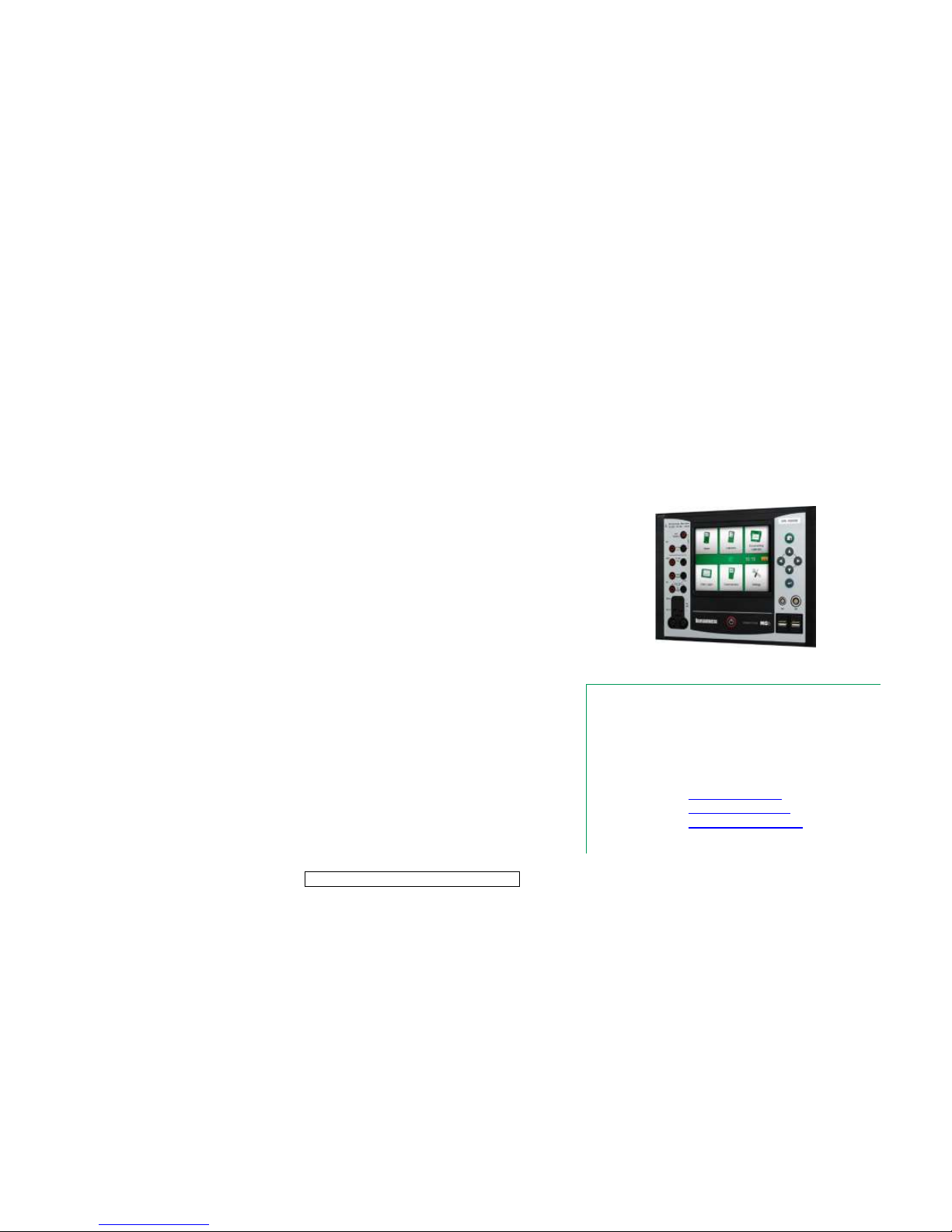
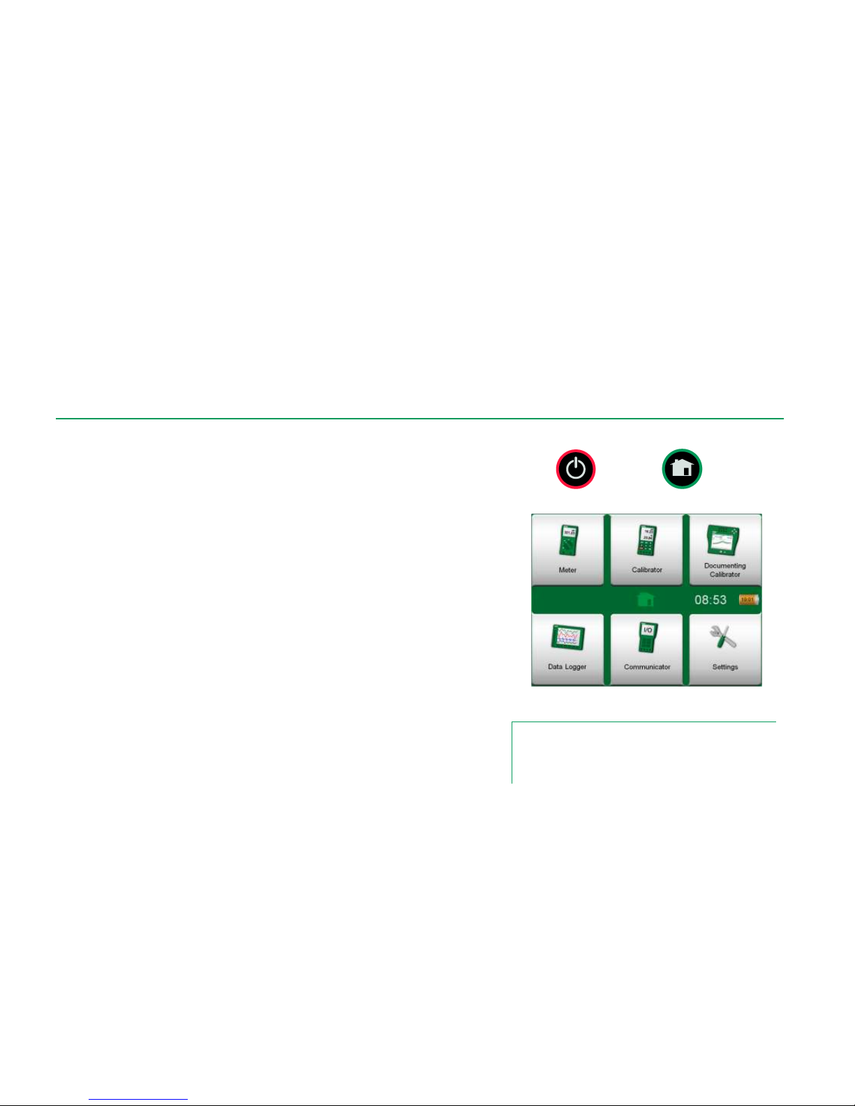
STARTING MC6 WORKSTATION
To start MC6 Workstation, switch the MCS200 Module Rack on and then press
MC6 Workstation's Power button for a few seconds. The startup procedure
ends in Home View (see picture on the right). From MC6 Workstation's Home
View you may advance to any of the available main functions. This manual contains detailed information of main functions as follows:
Meter in Part 3,
Calibrator in Part 4,
Documenting Calibrator in Part 5,
Data Logger in Part 6,
Communicator in Part 7 and
Settings in Part 8.
With the Home button (see picture on the right) you can always return to Home
View from wherever you are.
When MC6 Workstation is already running, pressing the Power button briefly
opens a dialog with the following options:
Power Off to shut down MC6 in Backup Mode, i.e. minimum power
consumption and full startup procedure.
Standby to set MC6 Workstation in Standby Mode allowing faster
startup when the Power button is pressed again.
Backlight Off to temporarily set the backlight off.
The button on the right side of the dialog:
Power Management to define Backlight Brightness and other power
management related settings. More in Part 8, Settings.
Power button (left) and Home button (right).
Home View
Note.
Certain main functions are options. They may not be available
in your MC6 Workstation. More of this in chapter Options on
page 13.
Page 13
About MC6 Workstation - Firmware 5
FIRMWARE
You can interact with MC6 Workstation by tapping on available buttons/controls
displayed on the touch screen. Optionally: use the hardware arrow keys to
move between the available buttons/controls. The first time you push a hardware arrow key the Hardware Focus Indicator is displayed (a blue border
around the active button/control). When using the hardware arrow keys, use the
hardware Enter key to select ("tap") a button/control.
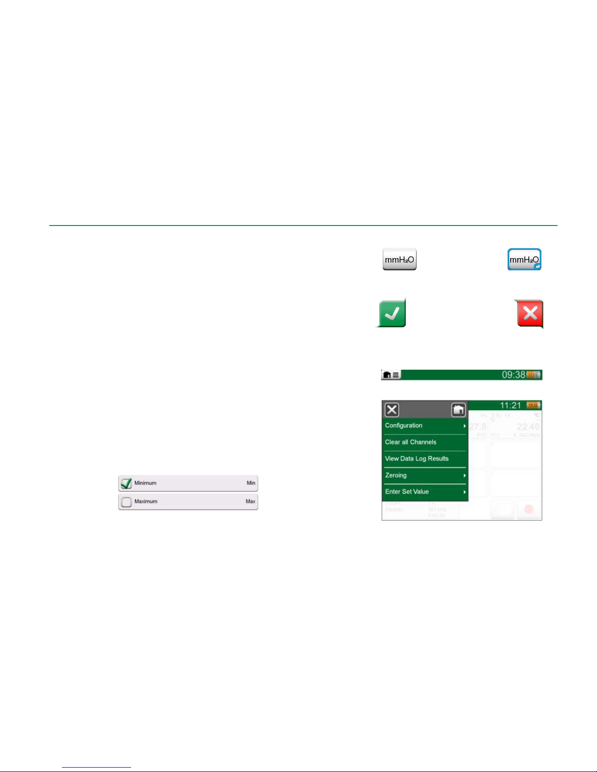
Buttons often open a pop-up window for entering data, e.g. a unit button with
the text "mmH2O" opens a pop-up window of available units. Certain buttons do
have special functionality, like "Accept" and "Close" buttons. They close a popup window and either accept or reject the changes. There are other buttons,
e.g. for going to the next/previous page pages, scrolling through a wide table of
data, removing a number in a numeric field (backspace), clearing a numeric
field, etc. Most of them are familiar since they look similar as in personal computer software.
One important button is the Menu button which is available in the upper left
corner of almost any window. Tap on it to open a context-sensitive menu with,
among other things, a software version of the Home button presented on previous page.
Check Boxes are special buttons that are either "checked" or "unchecked".
See picture below. Again, the functionality is familiar from personal computers.
Check Boxes, both a checked
and an unchecked one.
Button without and with a Hardware Focus Indicator.
Accept button. Close button.
Menu button to the left.
Example of an opened menu.
Page 14
6 MC6 Workstation, User Manual – Part 1, Introduction
MC6 Workstation also has some "flat" buttons. They are used in, e.g lists. The
color of the flat buttons may vary depending on the context.
The following editable fields are available:
Text Fields,
Numeric Fields, in certain cases including Spinning and
Date/Time Fields.
The letters/numbers on all editable fields are blue to indicate that they are editable. Black texts are descriptive user interface texts that are not editable. An
example of a Text Field and the Text Edit Window is at the bottom right of this
page.
Use of Numeric Fields and Spinning is described in Part 2, Active Terminals
and Connections and Part 5, Documenting Calibrator.
Date Fields are actually special cases of Numeric Fields. Entering the date is
just like entering any numeric value.
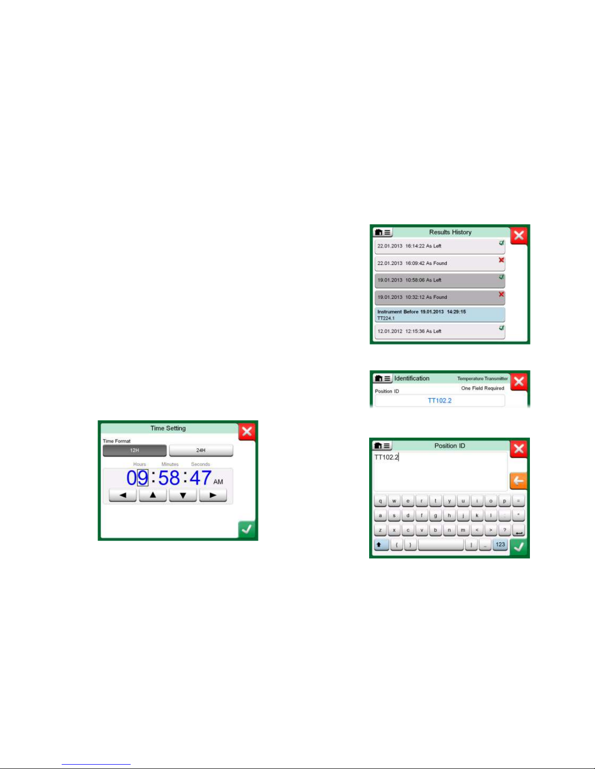
Setting MC6 Workstation's time is a special case of the Spinning functionality.
See picture below. The "Left" and "Right" arrow buttons move the highlight to
another digit. The "Up" and "Down" arrow buttons change the value of the highlighted digit.
Time Setting window
Example of a list with flat buttons.
Text Field
Text Edit window
Page 15
About MC6 Workstation - Hardware 7
HARDWARE
GENERAL
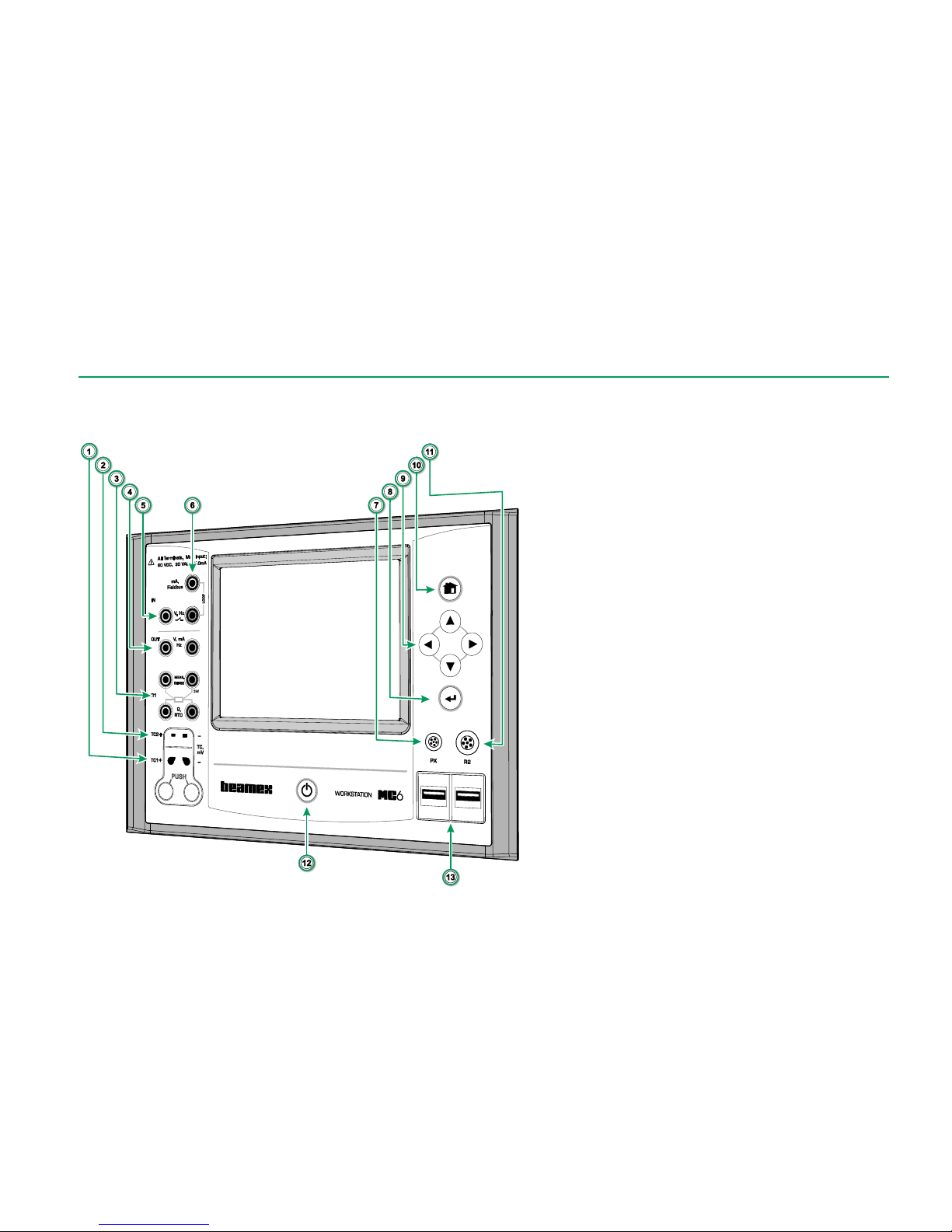
MC6 Workstation, front view.
Legend:
1. Thermocouple connector (TC1) with release but-
tons. For cables and standard TC plugs.
2. Thermocouple connector (TC2). For TC plugs with
flat contacts.
3. RTD and Resistor connector (R1). An R2 connector
is on the top of MC6 Workstation. More of R2 con-
nector on page 9.
4. Voltage, Current and Frequency output (OUT).
5. Voltage, Frequency and Switch input (IN ).
6. Current Measurement, Loop Supply, HART® and
Fieldbus connection (IN).
7. Connector for External Pressure Modules (PX).
8. Enter button for selecting the item surrounded with
the Hardware Focus Indicator.
9. Arrow buttons. First press displays the Hardware
Focus Indicator. Further presses move the indicator
on the touch screen.
10. Home button. Press this button to return to Home
View.
11. R2 connector. A possibility to connect an external
RTD sensor to MC6 Workstation. See also Hard-
ware Modules/Options and Accessories on page
14.
12. Power button. More in chapter Starting MC6 on
page 4.
13. Two USB-A connectors for connecting USB devices
to MC6 Workstation. See also chapter Firmware
Update in the Appendix.
Page 16
8 MC6 Workstation, User Manual – Part 1, Introduction
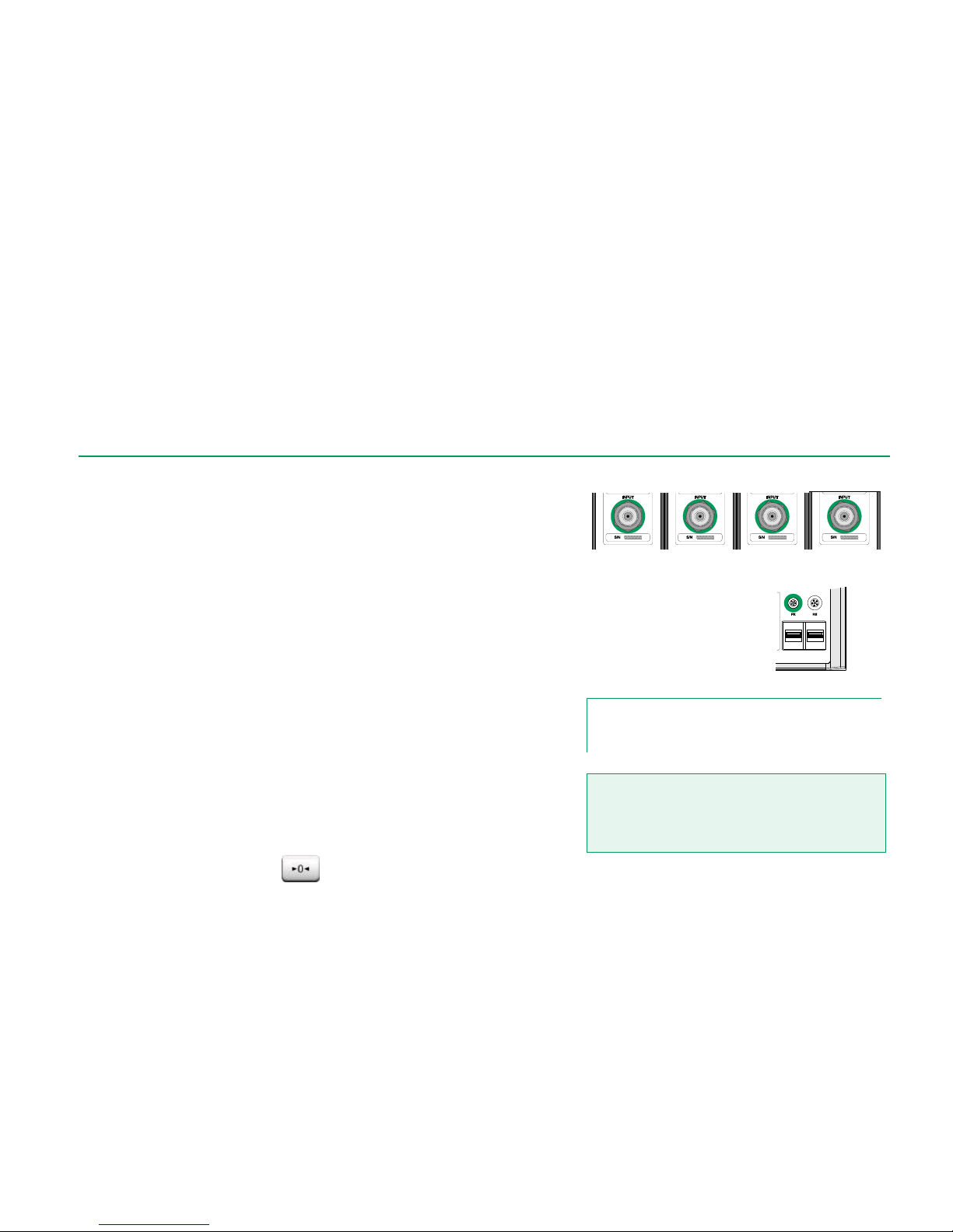
PRESSURE MODULES
MC6 Workstation supports up to nine pressure modules plus a barometric
module connected to it via a daisy chain communication cable inside MCS200.
The amount of modules varies depending on the system at hand. MC6 Workstation's User Interface refers to Pressure Modules as PX: P1C.
Where:
X is the ID address of a pressure module (0 to 9)
P1C etc. are the pressure module types.
The recommended pressure medium for pressure modules is clean air. Clean
non-corrosive liquids may optionally be used in modules with a measuring
range of 20 bar/300 psi or more. Avoid spilling liquid on MC6 Workstation when
connecting/disconnecting pressure hoses to/from pressure modules.
To avoid damaging the module, use hand tightening only when connecting the
pressure measurement hoses (max. torque 5 Nm, approx. 3.6 lbf ft). If the use
of tools is required to secure the connection (typically pressure modules with a
pressure range higher than 20 bar), apply the counterforce by placing a 14 mm
(approx. 9/16”) A/F spanner on the flats found in the module’s connector. The
overpressure protection of the internal pressure modules vents to the inside of
the module rack.
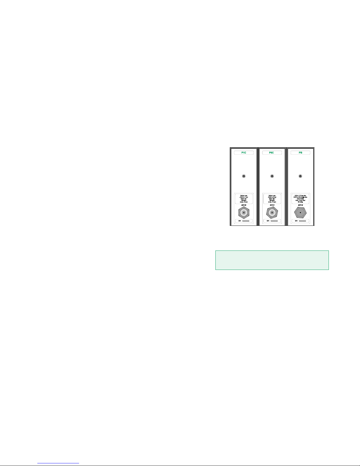
Barometric Module
Barometric Modules are shown as PB: PB in the MC6 Workstation's User Interface. The connection in front of a Barometric Module is meant for calibration
use. The thread is M5. To ensure valid barometric pressure measurements, do
not use the connection unless calibrating the module.
See Appendix for information on installing and uninstalling Pressure Modules.
Example of a set of Pressure Modules
in MCS200.
Remember to be cautious when working with pressure and
pressure modules. See also Appendix, chapters Safety
and Safety Precautions and Warnings.
Page 17
About MC6 Workstation - Hardware 9
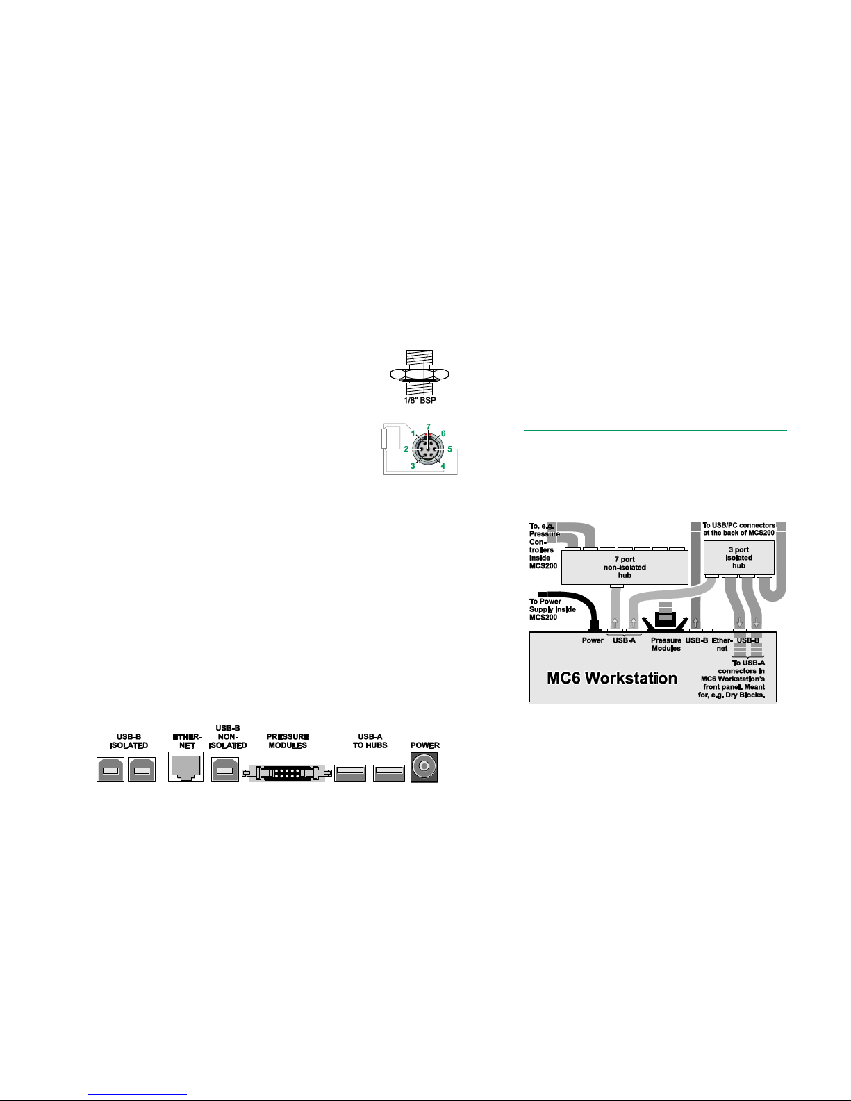
FRONT PANEL CONNECTION DETAILS
If you use other pressure hoses than the one delivered by
Beamex, remove the connector meant for Beamex's pressure hoses and replace them with your own connectors.
The thread available in a Pressure Module's body is 1/8"
BSP.
R2 connector's pin order:
Outside view of the female
connector in MC6 Workstation.
1 Excitation current +
2 Sense +
4 Sense 5 Excitation current -
Note.
Leave pins 3, 6 and 7 unconnected in the male connector
meant for MC6 Workstation's R2 connector.
CONNECTORS AT THE BACK OF MC6 WORKSTATION
The rear end of MC6 Workstation (inside MCS200) includes the same connectors as in a portable MC6. There's also a Pressure Module connector for connecting Pressure modules in MCS200. See picture below.
USB Ports
The need for USB connectors in MC6 Workstation may be more than is available in a portable MC6. There may be several pressure controllers etc. in
MCS200 that requires communication with MC6 Workstation. That is why there
are two hubs included with MC6 Workstation inside MCS200. Two of the isolated hub's ports are connected to the USB-A ports in MC6 Workstation's front
panel allowing communication with, e.g. Dry Blocks.
A USB-B connector in MC6 Workstation is connected to the rear of MCS200. It
is meant for PC communication. Another USB-A connector is available via the
isolated hub. See rightmost picture.
Rear view of MC6 Workstation (inside MCS200).
Default connections inside MCS200.
Top view of MC6 Workstation.
Note.
All USB connectors are USB 2.0 Full Speed ports
Page 18

10 MC6 Workstation, User Manual – Part 1, Introduction
MEMORY
MC6 Workstation maintains data very much like personal computers. Data is
saved on a solid state memory that does not need any power to maintain its
state. Solid state memory is shock-proof so the data is not lost when the calibrator is transported. Also, you can safely save a large amount of instruments,
calibration results and data log results.
Available memory can be used for anything that requires it (e.g. instrument data, calibration results etc.).
DISPLAY
MC6 Workstation has a backlit 640 × 480 pixel 5.7" TFT touch screen display.
Use the touch screen with your fingers, gloves on or off. Optionally, use a stylus
meant for touch screen use.
See also brightness settings in Part 8, Settings.
Warning!
Using sharp tools such as a screwdriver on the touch
screen may damage it. More warnings in Appendix.
Page 19

About MC6 Workstation - Hardware 11
BATTERIES
MC6 Workstation has internal rechargeable Lithium Polymer (LiPo) batteries for
powering the internal clock when MCS200 is shut off. The charger is connected
to MCS200's power supply so the battery is automatically charged when
MCS200 is on. LiPo batteries do not suffer from the memory effect, so they may
be charged at any time. However, there are some serious safety issues concerning them, so read Warnings Concerning the Lithium Polymer Battery
Pack in Appendix.
A picture of a battery (or a plug, when charging or running on AC power) is
shown on many of MC6 Workstation's views. The "content" of the battery corresponds to the approximated charge level of MC6 Workstation's rechargeable
batteries. The maximum operating time of the batteries without recharging varies depending on the usage of the display back light. The usage of the 24 V
transmitter supply also affects the maximum operating time. Even with constant
maximum load, the standard rechargeable batteries should last for 10 hours. A
good average operating time is 16 hours.
The capacity of all batteries deteriorate with time. If MC6 Workstation's internal
clock is reset, it is time to replace the battery pack with a new one. See Appen-
dix for information on how to replace the Battery Pack.
Full battery Empty Battery
Notes.
A time approximate (hh:mm) is shown on the battery symbol.
During charging it is the charging time left, otherwise it is remaining usage time.
MC6 Workstation's internal clock/calendar uses a small
amount of power even when MCS200/MC6 Workstation is
switched off. Remember to check the capacity of the batteries
from time to time when MC6 Workstation is not in use. Recharge if needed.
Tap the battery icon to open a window displaying detailed battery/charging information.
Page 20

12 MC6 Workstation, User Manual – Part 1, Introduction
PC COMMUNICATION / CALIBRATION SOFTWARE
Beamex CMX Calibration Software supports MC6 Workstation from version
V2, revision 2.8 and onwards and also in Beamex LOGiCAL, a cloud based
tool for handling calibration results.
USB COMMUNICATION DRIVER
MC6 uses Windows' generic USB driver (WinUSB) provided by Microsoft. Supported operating systems: Windows® 7 … Windows® 10. Starting from Windows
8, the driver installation is self-contained, older versions may require Windows
Update connection.
MC6 WORKSTATION RELATED TOOLS AVAILABLE FOR PC
The following tools are available for download at Beamex's web site:
https://www.beamex.com. Look for Download Center and Software tools
for MC6 family.
Beamex MC6 Data Log Viewer, for transferring Data Log results to a
PC and viewing them on the PC.
Beamex MC6 Device Description Installer, for installing new Device
Descriptions of smart transmitters from a PC to MC6.
Beamex MC6 Fieldbus Configuration Viewer, for downloading smart
transmitter configurations read into MC6 to a PC.
Beamex MC6 Remote Controller, for controlling MC6 Workstation via
a PC.
Page 21

Options - Software Options 13
OPTIONS
SOFTWARE OPTIONS
The following software options are available:
Documenting Calibrator including computer communication with sup-
ported calibration software presented in chapter PC Communication /
Calibration Software on page 12,
Mobile Security Plus. This option requires that you have the Docu-
menting Calibrator option in MC6 and CMX Calibration Software ver-
sion V2, revision 2.11 or later.
Multi channel Data Logger,
Communicator, HART®,
*)Communicator, FOUNDATION Fieldbustm,
*)Communicator, PROFIBUS PAtm,
+)Drivers for External Controllers (Pressure and Temperature) and
Special Temperature Sensors.
*) Requires that communicating hardware is installed into MC6. Please con-
tact Beamex.
+)
When necessary, a connection cable is shipped when the software option
is bought.
Notes.
The software options available in the MC6 at hand can be
found in MC6's Settings main function. Select About option
and browse to page 3.
Whether the communication hardware needed for fieldbus
communication is installed or not, can be found in MC6's Set-
tings main function. Select About option and see page 1.
Page 22

14 MC6 Workstation, User Manual – Part 1, Introduction
HARDWARE MODULES/OPTIONS AND ACCESSORIES
Pressure Modules. Up to nine gauge and/or differential pressure mod-
ules may be installed in MCS200's Module Rack and additionally a barometric module.
Communicating hardware for MC6's Communicator software options.
See also Software Options on page 13.
Adapter cables for R2 connector. The R2 connector supports Beamex
Smart Reference Probe.
Cable for Pressure and Temperature Controllers.
Spare Battery Pack.
Pressure Hose Sets to be used together with internal and external
Pressure Modules.
Note.
The Pressure Modules internally connected to the MC6 Workstation at hand can be found in MC6's Settings main function.
Select About option and browse to page 2.
RELATED PRODUCTS
There are an increasing number of devices that can be used together with MC6
Workstation. The following list includes devices that are already available (valid
when this manual was printed):
External Pressure Modules (EXT),
Calibration hand pumps:
- PGV vacuum pump,
- PGL low pressure calibration pump,
- PGC pressure/vacuum pump,
- PGM high pressure pump,
- PGPH high pressure pneumatic pump and
- PGXH extra high pressure pump.
Beamex POC8 Automatic Pressure Controller,
Beamex Field Temperature Block (FB Series),
Beamex Metrology Temperature Block (MB
Series),
Beamex CMX Calibration Software and
Beamex LOGiCAL, a cloud based tool for
handling calibration results.
Page 23

Things discussed in this part:
A presentation of measurements MC6 Workstation is
capable of performing. For all measurements, the active terminals together with useful additional information for that particular measurement are presented.
Similarly, a presentation of generations and simula-
tions MC6 Workstation is capable of performing.
For generations/simulations, there is also information
on how to change the generated/simulated value.
Part 2
ACTIVE TERMINALS AND CONNECTIONS
Page 24

16 MC6 Workstation, User Manual – Part 2, Active Terminals and Connections
GENERAL
This section of MC6 Workstation's User Manual presents all measurements and
generations/simulations that MC6 Workstation is capable of performing. No
matter which of the available main functions you use in MC6 Workstation, the
connections presented here apply.
Settings in Meter and Calibrator are saved, so the next time you measure,
generate or simulate something, the previous settings are available as defaults.(*
In Calibrator also the additional information row settings for all measurements/generations/simulations are saved for future needs. However damping,
resolution and alarms are active for the current session only.
*) When you use Documenting Calibrator and select an instrument for cali-
bration, the instrument's settings (Quantity, Port etc.) are inherited to the
Calibrator.
Respectively, when creating a new instrument in Documenting Calibrator,
the settings in Calibrator's sub-windows are used as default settings for the
new instrument's input and output.
Notes.
For HART and Fieldbus instrument specifics, see Part 7,
Communicator.
For information on External Devices (Pressure and Temperature Controllers) used together with Calibrator and Documenting Calibrator, see Part 9, Additional Information.
Note.
In this manual, when presenting each measurement/generation/simulation there is a picture with highlighted active terminals. The highlight for possible optional connections is lighter.
Connections to instruments are included if it requires special
attention. See, e.g. Current Generation (Source or Sink) on
page 24.
Next…
Measurements on page 17
Generations/Simulations on page 22
Meter in part 3
Calibrator in part 4
Documenting Calibrator in part 5
Data Logger in part 6
Communicator in part 7
Additional Information in part 9
Page 25
Measurements - Pressure Measurement 17
MEASUREMENTS
PRESSURE MEASUREMENT
MC6 Workstation supports the use of both pressure modules in MCS200, if
installed, and the use of supported external pressure modules, when they are
connected to MC6 Workstation.
Note that pressure measurement requires knowledge of pressure types (absolute pressure, gauge pressure and differential pressure). Measuring pressure
with inadequate knowledge of pressure types and the dangers of pressure devices may result in false measurement results and/or serious accidents. Please
read the warnings in Appendix.
CONNECTING AND DISCONNECTING EXTERNAL PRESSURE MODULES
When an external pressure measurement module is connected and when applicable, MC6 Workstation opens a dialog. Among other information, the dialog
includes a possibility to choose where to use the connected external pressure
module.
An external pressure module may be disconnected at any time. MC6 Workstation indicates that an external pressure module was removed. If the module
was used for a measurement, the measurement stops.
ZEROING A PRESSURE MODULE
If the selected pressure module does not display zero gauge pressure when the
applied pressure is zero, the module has to be zeroed. To do it, apply zero
gauge pressure and tap the zero button:
Example of pressure module connectors in MCS200.
PX, Connector
for external pressure measurement
modules in MC6
Workstation (right).
Note.
The amount of pressure modules in MCS200 on your particular
MC6 Workstation may differ from the picture presented above.
Warning!
Select a pressure module that has a suitable measurement
range for your pressure signal. Too low/high measurement
range on the pressure module results in faulty modules,
imprecise readings or even accidents.
Page 26
18 MC6 Workstation, User Manual – Part 2, Active Terminals and Connections
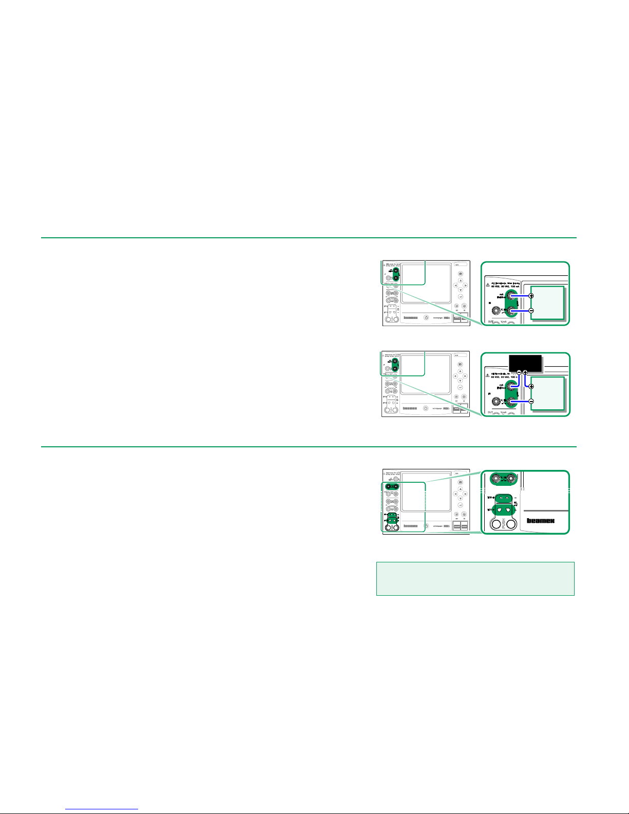
CURRENT MEASUREMENT
When measuring electric current, an important thing is selecting whether MC6
Workstation provides the 24 volt loop supply voltage or not. If not, an external
device should provide the loop supply voltage.
Connection depends on the loop supply setting. See pictures to the right.
See also: Current Generation (Source or Sink) on page 24.
Current measurement terminals. Internal supply
Range -101 … +101 mA
Current measurement terminals. External supply.
VOLTAGE MEASUREMENT
MC6 Workstation's voltage measurement terminals are listed below (top to bottom) as they are shown in the adjacent picture (left to right):
TC1, measurement range: -1.01 to +1.01 VDC.
TC2, measurement range: -1.01 to +1.01 VDC.
IN, measurement range: -1.01 to +60.6 VDC.
Note that you may measure non-supported thermocouple signals using either
TC1 or TC2 port. The reading is in (milli)volts, so you need a data table to convert the signal to temperatures. Calibrator‘s and Documenting Calibrator's
Scaling utility may be used for converting millivolts to temperatures.
See also: Voltage Generation on page 24 and
Temperature Measurement (Thermocouple) on page 19.
Voltage measurement terminals.
For ranges, see chapter to the left.
Warning!
Do not apply hazardous voltages to MC6 Workstation's
terminals.
Instrument
controlling
current
signal
External
Power Supply
Instrument
controlling
current
signal
Page 27
Measurements - Temperature Measurement (Thermocouple) 19
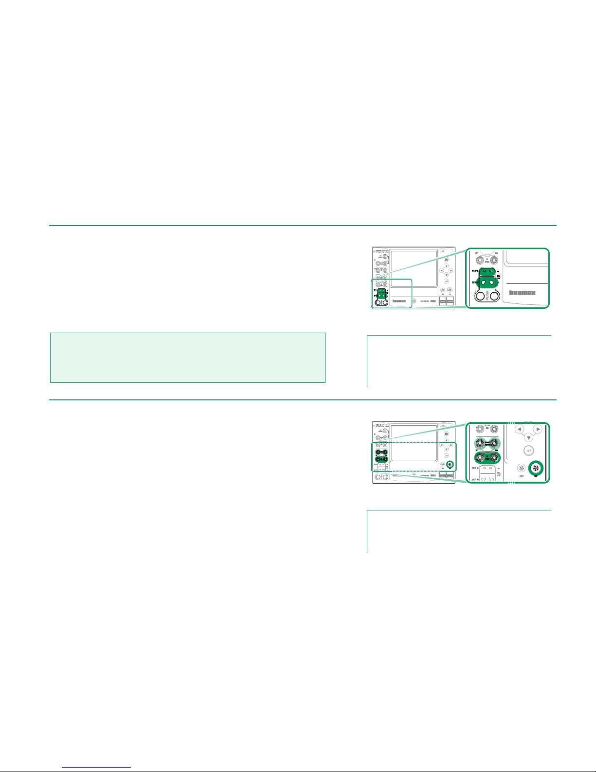
TEMPERATURE MEASUREMENT (THERMOCOUPLE)
MC6 Workstation has two thermocouple connectors. TC1 is for cables and
standard TC plugs. TC2 is for TC plugs with flat contacts.
Check the Sensor Type. Your measurement results are unreliable unless you
select the same sensor type as is connected to MC6 Workstation. Select also a
suitable Reference Junction compensation method. Wrong settings yield useless measurement results.
See also: Thermocouple Simulation on page 25 and
Voltage Measurement on page 18.
Warning!
When using another thermocouple or an RTD sensor connected to MC6 Workstation to
measure the external reference junction temperature: Keep in mind that there is no isolation between the thermocouple to be calibrated and the sensor measuring the reference temperature.
Thermocouple measurement terminals.
Range depends on sensor type
Note.
Thermocouple measurements are error prone. There may be
faulty connections, wrong (extension) cables and settings in
MC6 Workstation. If unsure, see chapter Thermocouple Con-
nections on page 28 and study thermocouple literature.
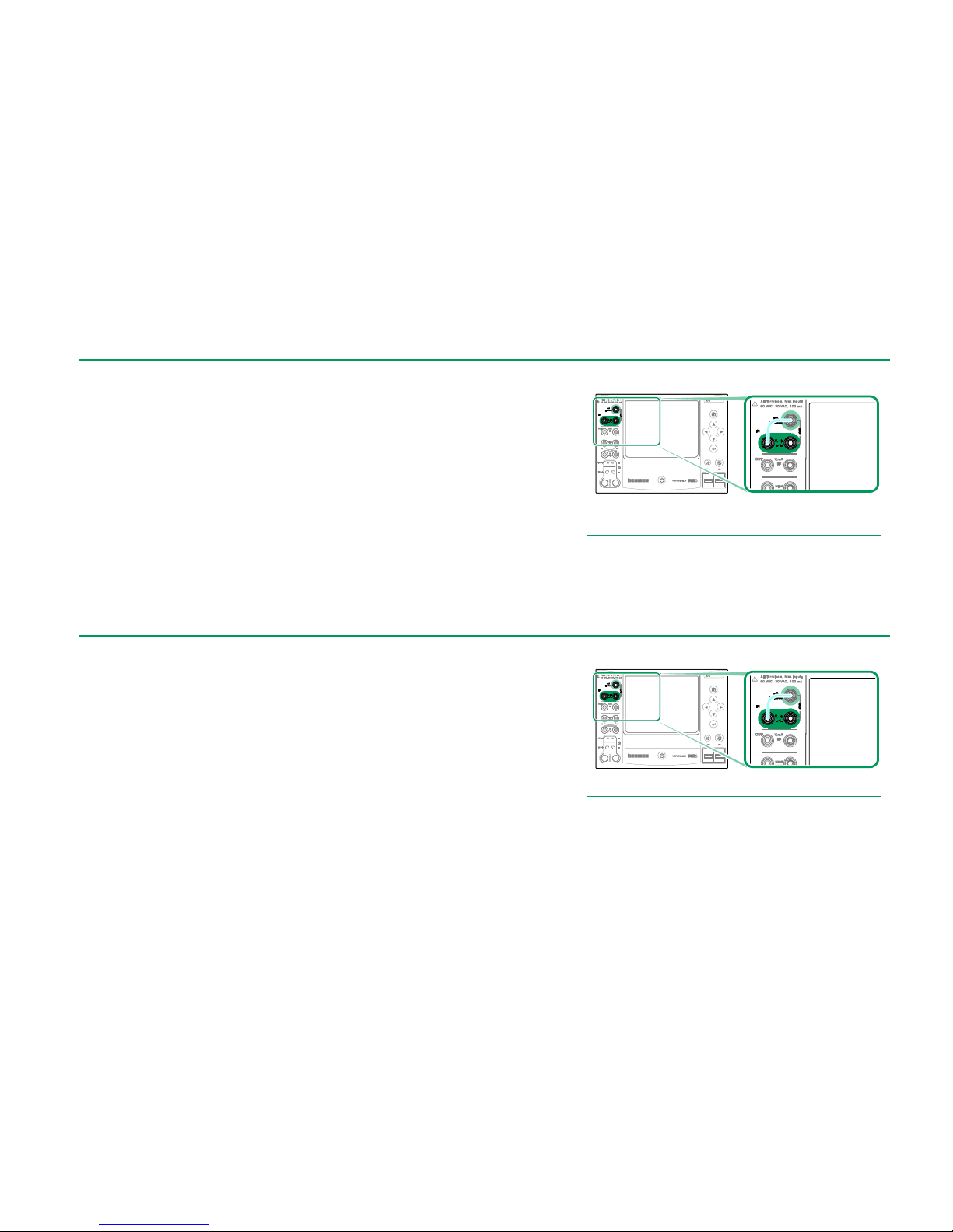
TEMPERATURE MEASUREMENT (RTD)
Check the sensor type. Make sure you select the same sensor type as is connected to MC6 Workstation. Otherwise your measurement results are unreliable.
For R1 terminals:
The two leftmost terminals are used in 2-wire systems. MC6 Workstation automatically checks the connection and displays the found wiring system.
For R2 terminal:
Beamex offers, as an option, an adapter for the R2 terminal. Please contact
Beamex for details. R2 terminal always uses 4-wire measurement.
See also: RTD Sensor Simulation on page 25,
Resistance Measurement on page 20 and
Resistance Simulation on page 26.
RTD measurement terminals.
Range depends on sensor type
Note.
If you get "+OVER" or “-OVER” error messages, check the
connections. If necessary, use 2-wire ohm measurement to
check the wiring.
Page 28
20 MC6 Workstation, User Manual – Part 2, Active Terminals and Connections
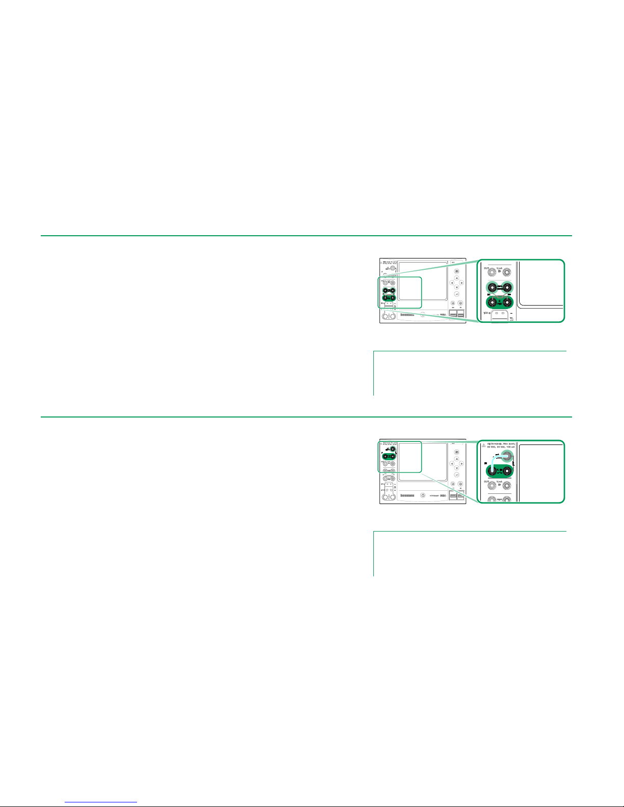
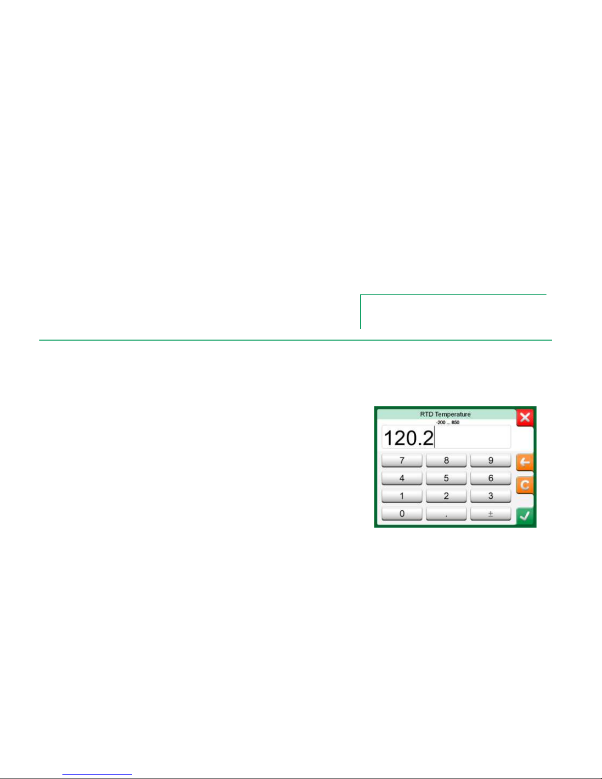
RESISTANCE MEASUREMENT
For R1 terminals:
The two leftmost terminals are used in 2-wire systems. MC6 Workstation automatically checks the connection and displays the found wiring system (2-wire,
3-wire or 4-wire).
For R2 terminal:
Beamex offers, as an option, an adapter for the R2 terminal. Please contact
Beamex for details. R2 terminal always uses 4-wire measurement.
See also: Resistance Simulation on page 26 and
Temperature Measurement (RTD) on page 19.
Resistance measurement terminals.
Range -1 … 4040 ohm
Note.
If you get "+OVER" or “-OVER” error messages, check the
connections. If necessary, use 2-wire ohm measurement to
check the wiring.
FREQUENCY MEASUREMENT
In frequency measurement, be sure you select a suitable trigger level setting.
To do it, tap on the button with the arrow pointing on a rising ramp and the current trigger level voltage. From the opened pop-up window: Select a suitable
trigger level.
See also: Frequency Generation on page 26,
Pulse Counting on page 21 and
Switch Sensing on page 21
Frequency measurement terminals.
Range 0.0027 … 51000 Hz
Note.
There is a trigger level choice for (dry) contacts with no external potential. 24V supply may also be used. Connect as light
blue line shows in picture above.
Page 29
Measurements - Pulse Counting 21
PULSE COUNTING
Pulse counting has three settings that should be checked before (re)starting a
pulse count:
Trigger level. Select a level that suits your signal.
Trigger edge. Select either rising or falling edge.
Zeroing. A possibility to zero the pulse count.
See also: Pulse Generation on page 27,
Frequency Generation on page 26 and
Frequency Measurement on page 20.
Pulse counting terminals.
Range 0 … 9 999 999 pulses
Note.
There is a trigger level choice for (dry) contacts with no external potential. 24V supply may also be used. Connect as light
blue line shows in picture above.
SWITCH SENSING
Switch Sensing has three settings:
A possibility to invert switch's open/close state indication.
Trigger level. Select a level that suits your switch. See note to the right.
Sound setting. Define whether MC6 Workstation emits a sound when
the switch's state change and if yes, when it is emitted.
See also: Pulse Counting on page 21 and
Pulse Generation on page 27,
You can also use Switch Sensing for binary signal detection. For normal switch
state detection: an open switch equals 1 / True and a closed switch 0 / False.
Switch sensing terminals.
Note.
There is a trigger level choice for (dry) contacts with no external potential. 24V supply may also be used. Connect as light
blue line shows in picture above.
Page 30
22 MC6 Workstation, User Manual – Part 2, Active Terminals and Connections
GENERATIONS/SIMULATIONS
Generations and simulations are supported in Calibrator, Documenting Calibrator and Data Logger.
Note.
The Meter is not capable of performing generations and simulations.
CHANGING THE GENERATED/SIMULATED VALUE
There are several ways of changing the generated/simulated value. The following subchapters present the available utilities.
USING THE SOFT NUMERIC KEYPAD
This utility is useful when a generated/simulated value (or any numeric field in
MC6 Workstation) is either empty (displaying dashes) or when a new and different value is needed. The soft numeric keypad opens when you tap on the
generated/simulated value (see picture to the right).Tap on numbers to enter a
value. Additional functions:
Use the "C" key on the right to clear the entered value.
Use the "Left Arrow" key to delete the number to the left of the cursor.
The entered value is taken into use when you close the window using the "Accept" button. Note that MC6 Workstation may use the entered value as a
source for the value's resolution. Enter trailing zeros to ensure useful resolution.
When applicable, the minimum and maximum limit of the entered value is shown
above the entered number. If you enter a value above/below the limits, and try to
accept it, MC6 Workstation stays in the soft numeric keypad window and replaces
the entered value with appropriate limit value and highlights the replaced value.
Soft Numeric Keypad.
Page 31

Generations/Simulations - Changing the Generated/Simulated Value 23
SPINNING
Spinning is a tool that is available in Calibrator and Documenting Calibrator.
It is useful when making small changes to an existing numeric value, one digit
at a time.
Non-empty numeric fields in Calibrator's generation/simulation windows have a
button with both "Up" and "Down" arrows to the left of the actual numeric value.
That is the Spinner button. Tap the Spinner button to activate spinning.
When spinning is active, one of the digits is highlighted. Change its value by
tapping the "Up" and "Down" arrows in the active spinner. To move the highlight to another digit, use the "Left" and "Right" arrows.
To stop spinning, tap the Spinner button again.
Inactive spinner
Active spinner
Notes.
Any changes in the numeric field are immediately reflected in
the generated/simulated signal.
You cannot exceed the minimum/maximum limits of a Function
when spinning.
The spinned value follows the resolution properties of the generated/simulated Function.
If a numeric field is empty (displaying dashes), first use the soft
numeric keypad to enter a value. Then you are able to utilize
the spinning tool.
Page 32

24 MC6 Workstation, User Manual – Part 2, Active Terminals and Connections
CURRENT GENERATION (SOURCE OR SINK)
MC6 Workstation's current generation can be done using one of two available
methods:
MC6 Workstation provides a 24 volt loop supply voltage (source mode).
Setting: Supply: On.
An external device provides the loop supply voltage (sink mode)
Setting: Supply: Off.
Connection depends on the loop supply setting. See pictures to the right.
See also: Current Measurement on page 18.
Note.
If the connected instrument utilizes digital communication and MC6 Workstation's 24 volt supply voltage is in use, the following battery symbol is shown in the user interface of Document-
ing Calibrator and Data Logger:
Current generation terminals. Internal supply.
Range 0 … 55 mA
Current generation terminals. External supply
VOLTAGE GENERATION
MC6 Workstation has two voltage generation terminals. They are listed below
(top to bottom) as they are shown in the adjacent picture (left to right):
TC1, generation range: -1 to +1 VDC.
OUT, generation range: -3 to +24 VDC.
Note that you may simulate non-supported thermocouple signals using TC1
port. Since you actually generate (milli)volts, you need a data table to convert
desired temperatures to millivolts.
See also: Voltage Measurement on page 18 and
Thermocouple Simulation on page 25.
Note.
It is advisable to enter 0 V output before connecting the circuit.
Voltage generation terminals.
For ranges, see chapter to the left.
Warning!
Short circuiting the voltage output may result in damage to
MC6 Workstation and/or the connected instrument.
Instrument
receiving
current
signal
External
Power Supply
Instrument
receiving
current
signal
Page 33

Generations/Simulations - Thermocouple Simulation 25
THERMOCOUPLE SIMULATION
Thermocouple simulation is available from TC1 terminals only.
Check the Sensor Type. Your simulations are unreliable unless you select the
same sensor type as is connected to MC6 Workstation. Also select a suitable
Reference Junction compensation method. Wrong Reference Junction setting
yields useless results. See chapter Thermocouple Connections on page 28.
See also: Temperature Measurement (Thermocouple) on page 19.
Warning!
When using a thermocouple or an RTD sensor connected to MC6 Workstation to measure the external reference junction temperature: Keep in mind that there is no isolation
between the instrument to be calibrated and the sensor measuring the reference temperature.
Thermocouple simulation terminals.
Range depends on selected sensor type
Note.
Thermocouple measurements are error prone. There may be
faulty connections, wrong (extension) cables and settings in
MC6 Workstation. If unsure, see chapter Thermocouple Con-
nections on page 28 and study thermocouple literature.
RTD SENSOR SIMULATION
RTD simulation is available from R1 terminals only.
Use of 2-, 3- or 4-wire connection is up to the receiving instrument. Connect the possible third and fourth wire according to the requirements of
the connected instrument, but use only the two leftmost R1 terminals
in MC6 Workstation. See adjacent picture.
Check the Sensor Type. Make sure you select the same sensor as the
instrument receiving the simulated signal requires. Otherwise your simulations are unreliable. See also note in next chapter.
See also: Temperature Measurement (RTD) on page 19 and
Resistance Simulation on page 26.
RTD simulation terminals.
Range depends on selected sensor type
Notes.
AC measurement current from the instrument under test is not
supported. With pulsed measurement current, set a wait time
of few milliseconds before the resistance is measured.
Instrument
receiving
simulation
signal
Page 34

26 MC6 Workstation, User Manual – Part 2, Active Terminals and Connections
RESISTANCE SIMULATION
Use of 2-, 3- or 4-wire connection is up to the receiving instrument. Connect the
possible third and fourth wire according to the requirements of the connected
instrument, but use only the two leftmost RTD1 terminals in MC6 Work-
station. See adjacent picture.
MC6 Workstation monitors the resistance measurement current. If the current is
too high, MC6 Workstation cannot simulate the right resistance value and displays an error message.
See also: Resistance Measurement on page 20 and
RTD Sensor Simulation on page 25.
Note.
When simulating resistance or an RTD sensor, using R1 port, MC6 Workstation does not support measuring the simulated signal using R2 port.
Resistance simulation terminals.
Range 0 … 4000 ohm
Notes.
AC measurement current from the instrument under test is not
supported. With pulsed measurement current, set a wait time
of few milliseconds before the resistance is measured.
FREQUENCY GENERATION
Before generating frequencies, the following settings should be checked:
Amplitude. Defined from the button with the "V" value.
Waveform and Duty Cycle. Set together from the rightmost button.
Duty Cycle is the ratio of the output high time to the total cycle time. Due to
technical reasons, the entered Duty Cycle is not always realized with relatively
high frequencies. When the realized Duty Cycle differs from the desired Duty
Cycle, the realized Duty Cycle is shown with an asterisk (*) in front of it, e.g.:
*8 %
See also: Frequency Measurement on page 20 and
Pulse Generation on page 27.
Frequency generation terminals.
Range 0.0005 … 50000 Hz
Instrument
receiving
simulation
signal
Page 35

Generations/Simulations - Pulse Generation 27
PULSE GENERATION
Before generating pulses, the following settings should be checked:
Frequency. To set the frequency, tap on the button with the "Hz" value.
Amplitude. Defined from the button with the "V" value.
Waveform and Duty Cycle. Set together from the rightmost button.
Duty Cycle is the ratio of the output high time to the total cycle time. Due to
technical reasons, the entered Duty Cycle is not always realized with relatively
high frequencies. When the realized Duty Cycle differs from the desired Duty
Cycle, the realized Duty Cycle is shown with an asterisk (*) in front of it, e.g.:
*8 %
See also: Pulse Counting on page 21 and
Frequency Generation on page 26.
Pulse generation terminals.
Range 0 … 9 999 999 pulses
Page 36

28 MC6 Workstation, User Manual – Part 2, Active Terminals and Connections
THERMOCOUPLE CONNECTIONS
With thermocouples, connections and reference junction settings are crucial for
getting accurate results. Reference Junction Modes available:
Internal is the simplest. Use suitable thermocouple, extension or compensation
wires to connect to MC6 Workstation. MC6 Workstation takes care of the Reference Junction compensation. The upper picture to the right presents the connection to TC1 terminals. You may optionally also use the TC2 terminals.
External R1 and External R2 use an external RTD sensor measuring the Reference Junction temperature, connected to selected terminal. The lower picture
to the right presents the connections to TC1 and R1 terminals.
Fixed (0°C) and Manual are used when a compensation box, a temperature
controller or similar method is utilized for fixing the Reference Junction temperature. Manual allows you to enter any temperature. Fixed (0°C) is a quick way of
"entering" zero degrees centigrade. Connection picture to TC1 below.
Fixed/Manual Reference Junction temperature.
Before measuring, ensure that MC6 Workstation's temperature has stabilized. Temperature differences between
MC6 Workstation and the environment affect the accuracy
of TC measurements.
Internal Reference Junction.
An RTD connected to R1 terminals measures
the Reference Junction temperature.
Copper
Fixed
Reference
Junction
Temperature
TC sensor
or a
TC signal receiver
TC materials
(TC, extension or
compensation wires)
TC sensor
or a
TC signal receiver
TC materials
(TC, extension or
compensation wires)
Reference temperature
TC sensor
or a
TC signal receiver
TC materials
(TC, extension or
compensation wires)
RTD
Copper
Page 37

Things discussed in this part:
Presenting the Meter and
how to take it into use.
Part 3
METER
Page 38

30 MC6 Workstation, User Manual – Part 3, Meter
ABOUT METER
The Meter can be used for quickly checking any device producing a signal that
is measurable with MC6 Workstation. For calibration needs, use one the calibration related main functions available in MC6 Workstation.
Start the Meter by tapping the Meter icon in MC6 Workstation's Home View
(see adjacent picture). A window like the one on the lower right corner of this
page opens. To measure a signal, do as follows:
Select the Quantity of the signal by tapping one of the nine buttons on
the lower part of the Meter window.
Other, Quantity dependent settings appear on top of the Meter window.
For information on connections and essential settings, see Part 2, Active Ter-
minals and Connections.
Home View with Meter selected
Current Measurement using Meter
Page 39

Things discussed in this part:
How to use the Calibrator
Presenting the available additional
Tools in Calibrator
Part 4
CALIBRATOR
Page 40

32 MC6 Workstation, User Manual – Part 4, Calibrator
ABOUT CALIBRATOR
The Calibrator can be used for calibrating instruments. It consists of two subwindows which can be independently(* configured to measure, generate or simulate a signal. One sub-window for the instrument's input and another for the
instrument's output.
Start the Calibrator by tapping on the Calibrator icon in MC6 Workstation's
Home View (see adjacent picture). A window like the one on the lower right
corner of this page opens. To configure a sub-window do as follows:
Select the Quantity of the signal by tapping the button in the upper left
corner of the sub-window. Hint: Quantity button has bold font.
Other, Quantity dependent settings appear to the right of Quantity but-
ton. The button closest to the Quantity button defines whether you
measure, generate or simulate a signal and which terminals are active.
For information on connections and essential settings, see Part 2, Active Ter-
minals and Connections.
Note.
If you want to document your calibration results, use MC6 Workstation's optional Document-
ing Calibrator feature or manually document the calibration data displayed in Calibrator.
For information on External Devices (Pressure and Temperature Controllers) used together
with Calibrator, see Part 9, Additional Information.
*) A measurement, generation or simulation in one sub-window reserve terminals in
MC6 Workstation. This may affect the availability of measurements, generations and
simulations in the other sub-window. To free terminals, tap on the quantity button
and in the opened window, tap on the "Stop" button.
Home View with Calibrator selected
Calibrator in use
Page 41

Tools - General 33
TOOLS
GENERAL
Calibrator window has Tools buttons in the lower left corner of each subwindow. See the picture to the right. The following list presents available tools.
Certain tools are available for measurements only and others for generations/simulations only.
Tool Description
Tools button. See also note below.
Scaling
Any signal may be scaled provided the conversion is
known. When scaling is active, it is indicated with a triangle in the unit button. The true measurement value is
shown in the additional info row at the bottom of the
sub-window.
Tools available for measurements.
Note.
For practical reasons, the available Tools are limited for
Switches.
Alarm
Main measurements may be assigned with four alarm
limits: high, low, high and low change rate. Active
alarms are shown above the main measurement.
When an alarm limit is exceeded, a warning signal is
heard. A button for acknowledging an alarm appears
when needed.
Leak / Stability Test
A leak/stability test may be assigned to main measurements. It tests the leak or stability of, e.g. a pressure
measurement system.
In the Leak / Stability Test configuration window: Enter
Test time and start recording. Use the "+30 sec" button
to increase the test time, when needed.
Continues on next page…
Page 42

34 MC6 Workstation, User Manual – Part 4, Calibrator
Tool Description
Tools available for generations and simulations.
Quick Access Buttons in use
Notes.
Several Tools have a "Stop" button in the pop-up window the
Tool is configured in. To stop, e.g. Damping, open the Damping configuration window and tap the "Stop" button. Then MC6
Workstation reverts to default damping settings.
Changing the Quantity of a sub-window revert all Tools, except
Additional Info settings, to their default settings for that particular Quantity.
In Calibrator window: the additional info fields with black text
may be zeroed "on the fly". Zeroing options are available in
Additional Info window's menu.
Some of the tools presented here are also available in Docu-
menting Calibrator and Data Logger.
Damping
Use damping when a measurement signal contains unwanted noise. Select one of the available options.
When Damping is used, a funnel appears to the left of the
main measurement. When damping is active, the following symbol is shown above the unit button:
.
Resolution
Any signal's resolution may be increased or decreased.
Altered resolution is indicated in sub-window, e.g. ".-2"
equals two less decimals.
Additional Info
Including additional information fields at the bottom of a
sub-window is always available. The available fields,
however, depend on the quantity/settings. Up to four
fields may be added to both sub-windows. The additional
information row settings are saved for future needs. See
also notes to the right.
Function Info
Always available. Opens a pop-up window with information of current function (measurement range, uncertainties etc.).
Step
Available for generations/simulations: Opens a window
for defining a step function for the generated/simulated
signal.
Ramp
Available for generations/simulations: Opens a window
for defining a ramp function for the generated/simulated
signal.
Quick Access
Available for generations/simulations: Opens a window
for defining five shortcuts to user configurable generation/simulation values. Quick Access buttons appear at
the bottom of the sub-window, taking over the space of
possible additional info data.
Page 43

Things discussed in this part:
An introduction to calibration
How to calibrate instruments using
MC6 Workstation's Documenting Calibrator
How to do a Group Calibration
How to view calibration results
How to read instrument data from devices
using digital communication
Part 5
DOCUMENTING CALIBRATOR
Page 44

36 MC6 Workstation, User Manual – Part 5, Documenting Calibrator
GENERAL
MC6 Workstation's Documenting Calibrator is an optional, more advanced
tool than the "plain" Calibrator that is also available in MC6 Workstation. If your
MC6 Workstation does not have this option installed, the Documenting Cali-
brator icon is disabled.
Documenting Calibrator saves instrument data and presents them in a list.
Instrument data consists of input and output quantities and ranges as well as
other data that defines the instrument. Starting to calibrate an instrument is fast,
since all the required data are immediately taken into use.
Instruments to be calibrated may be received from calibration software communicating with MC6 Workstation. Alternatively, instruments may be created in
MC6 Workstation itself.
Calibration results are saved and they can be viewed in MC6 Workstation and
also sent to calibration software for further analysis.
Open Documenting Calibrator by tapping on the Documenting Calibrator
icon in MC6 Workstation's Home View (see adjacent picture).
Home View with Documenting Calibrator
selected.
CALIBRATION SOFTWARE
When this manual was printed, the following calibration software supported
communication with MC6 Workstation:
Beamex CMX Calibration Software, version 2, revision 2.9. Light, Pro-
fessional and Enterprise editions.
Beamex LOGiCAL, a cloud based tool for handling calibration results.
Note.
Older Beamex calibration software do not support MC6 Workstation.
Page 45

Calibrating Instruments - Calibration Software 37
CALIBRATING INSTRUMENTS
Instruments are typically calibrated following the procedure shown in the adjacent picture.
In MC6 Workstation, you first select (or create) the instrument to be calibrated.
Then perform the As Found calibration – as many repeats as is required - and
decide whether or not adjustment is needed. Often you then do the required
amount of As Left repeats to document the instrument's state after the possible
adjustment.
A calibration procedure using MC6 Workstation is presented in the following
pages.
GENERATING/SIMULATING THE INPUT VALUE
How you change the generated/simulated value is explained in Part 2, Active
Terminals and Connections, chapter Changing The Generated/Simulated
Value.
Typical calibration procedure
Note.
Although MC6 Workstation assists you in doing the calibration,
you need to know how instruments are calibrated; be, e.g. a
calibration technician. MC6 Workstation is a tool for calibra-
tion professionals.
Page 46

38 MC6 Workstation, User Manual – Part 5, Documenting Calibrator
INSTRUMENT LIST
When you start the Documenting Calibrator, you arrive in Instrument List window. See adjacent picture for an example of an Instrument List.
MC6 Workstation allows you to hierarchically organize your instruments into a
Plant Structure. The Instrument List window may contain both instruments (gray
items) and Plant Structure Levels (yellow items). The following sub chapters
present features available in Instrument List window and its menu.
INSTRUMENTS
Instruments have a gray background in the Instrument List window. The instrument's upper text row displays the contents of one of the following fields: Posi-
tion ID, Name, Device ID or Device Serial Number. The first non-empty of the
aforementioned fields, in presented order, is displayed. The second row displays (possible) Function Name and Calibration Due Date data.
If the instrument has been calibrated, the rightmost end displays an icon. The
displayed icon depends on whether the instrument's latest calibration
"Passed", i.e. the found maximum errors were smaller than the instrument's
"Reject If" error limit, or did it "Fail". See pictures to the right.
To select an instrument for calibration, tap on it. Then the Instrument Over-
view Window, presented on page 40, opens.
To create a new instrument, tap the "Create New Instrument" button. See picture to the right. Then several pages of instrument configuration data opens.
Note that by default only basic pages are shown. View all pages by selecting
Show, All Pages from the menu available when creating/editing an instrument.
To delete an instrument, select it and use the delete command available in the
menu of opened Instrument Overview Window, presented on page 40.
Example of an Instrument List.
Note.
The Instrument List may be several pages long. Remember to
use the page browse buttons available on the right side of the
window.
Instrument's latest calibration "Passed"
Instrument's latest calibration "Failed"
"Create New Instrument" button
Page 47

Calibrating Instruments - Instrument List 39
PLANT STRUCTURE LEVELS
The name of the current Plant Structure Level is shown on the status bar. Tap
on the bar to see the full Plant Structure path. Plant Structure Sub Levels have
yellow background and the upper right corner is folded. The Level's name is
displayed and on the lower right corner, the amount of further Sub Levels + the
amount of instruments found on the next Sub Level.
To select a Plant Structure Level, tap on it. Then the contents of that level are
displayed. To return to the previous level, tap on the "Back" button found on
the right side of the Instrument List window.
Creating and managing Plant Structure Levels is presented in chapter In-
strument List Window Menu below.
INSTRUMENT LIST WINDOW MENU
The Instrument List window's menu contains a lot of useful tools:
Create New for creating a new Instrument etc. (See adjacent picture.)
Sort for sorting the list contents alphabetically etc.
Sorting icons shown in status bar (ascending / descending):
/ / /
Identification Due Date Creation
Show to display all or filter to a selected group of items in the list. The
group can be, e.g. all calibrated instruments. When filtering is active, the
following icon is shown in the status bar:
Plant Structure for defining how the Plant Structure is shown.
Browse to jump to start/end of list or finding instruments. When find is in
use, the following icon is shown in the status bar:
Management for deleting all Instruments/Results/Plant Structure levels
and also for moving/renaming Plant Structure levels.
Current Plant Structure Level is called "Pulp".
A total of 22 instruments are located on this
Level and all its Sub Levels. Sub Level
"Evaporation" has two Sub Levels and
18 instruments.
"Back" button
Notes.
Deleting a branch level also deletes all instruments and calibrations found on that level and all its sub levels.
You cannot delete the structure root level.
Warning!
Once an item is deleted, there is no way to retrieve it.
Instrument List Window's menu
Page 48

40 MC6 Workstation, User Manual – Part 5, Documenting Calibrator
INSTRUMENT OVERVIEW WINDOW
When an instrument is selected, the Instrument Overview window opens and
general data of the selected instrument is presented. See adjacent picture.
With the help of the buttons on the right side of the window, you may
edit/check the instrument data,
view calibration results for this instrument (if applicable) or
start calibrating the selected instrument and open the calibration window
(from the check mark on green background).
The bulleted list above is presented in the same order as the icons are in In-
strument Overview window.
Note that the menu contains some useful instrument related tools.
Instrument Overview Window
CALIBRATING AN INSTRUMENT USING MC6 WORKSTATION
When you start calibrating an instrument, the Calibration window opens. See
adjacent picture. Note that a possible Before Calibration Note window may
open before the Calibration window is shown.
Before you tap the Start button, ensure that the signals are "live", i.e. measurements and the required connections are as they should. If unsure, use the
connection diagrams found in the Instrument Overview Window. It opens from
the Info button.
If gauge pressure modules are used in the calibration, remember to zero them
before starting the calibration.
Tap the Start button to begin calibration. The rest depends on the instrument
setting: Automatic Acceptance.
Button for zeroing a pressure module in the
lower right corner.
Page 49

Calibrating Instruments - Calibrating an Instrument Using MC6 Workstation 41
When Automatic Acceptance is in use (checked), MC6 Workstation accepts
calibration point automatically as follows:
1. MC6 Workstation uses the Max. Point Deviation value to see if the input signal is close enough to the next calibration point.
2. When close enough, MC6 Workstation checks the signal stability to decide whether the readings can be saved or not.
3. When signal stability is reached, a timer counts down as set in Point
Delay and then the readings are saved only if the signal stability is still
valid. See hourglass in adjacent picture. If a signal becomes unstable,
MC6 Workstation returns to phase 2.
Use the Force Accept button to manually accept points when, e.g. the calibration does not advance because of an unstable input and/or output signal.
When Automatic Acceptance is not in use, every calibration point is manually
accepted. Then tap the Accept Point button seen in the Calibration window.
See lowermost picture to the right.
As the calibration advances, the graph is drawn from point to point. A grey column indicates where next target point is. The width of the grey column is based
on Max. Point Deviation setting. Numeric values for the next target point can
be seen in the lower right corner. If any of the points exceed the error limits
(blue dotted lines), the graph is colored red.
The Pause (||) button allows you to reject a calibration or undo a point. The
button with the "speech bubble" allows you to add notes to each calibration
point. For further options, open the menu.
If you need to change the Pressure Module during the calibration, see chapter
Changing the Pressure Module During Calibration on page 42.
Note.
Certain tools available in Calibrator are also available in Documenting Calibrator. To see
the tools, open Calibration window menu, select either Input or Output and from the opened
window, tap on the Tools button. The available tools depend on the Quantity and Port selected for the input/output. The same tools are also available when editing the instrument data.
Calibration with Automatic Acceptance in use.
Note.
Opening the menu during calibration pauses the calibration for
as long as the menu is open.
Calibration with manual acceptance.
Page 50
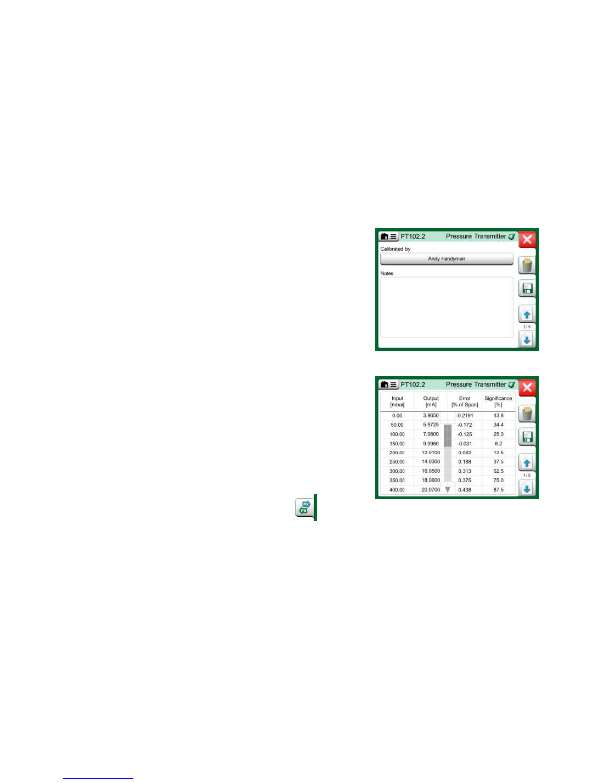
42 MC6 Workstation, User Manual – Part 5, Documenting Calibrator
When the calibration is completed, the first of Calibration Result window's pages open telling you whether the calibration Passed or Failed. Browse through
the pages to get an overview of the calibration results. Note that the amount of
pages shown depends on the setting found in the window's menu. To see the
basic pages only, open menu and select Show, Basic Pages. To see all pages
open menu and select Show, All Pages.
Save or delete the results using the buttons available on the right side of the
window. When saving: In the following window: Tap on the Combine with Pre-
vious Result check box, if you want to combine the most recent result with
previous results. When checked, calibration software treats all combined results
as one calibration event containing several repeats.
After saving the results, you are brought back to the Calibration window where
you may either start another calibration repeat or choose the Back button, to
end calibration for this instrument.
CHANGING THE PRESSURE MODULE DURING CALIBRATION
If a calibration requires the use of several Pressure Modules, the Pressure
Module has to be changed "on the fly". To do it, open Calibration window
menu, select either Input or Output (depending on where the Pressure Module
is connected). In the opened window:
If the module to be used is internal or you are changing from an Internal
Pressure Module to an already connected External Pressure Module,
just tap the button below Port/Function text and select it from the available Pressure Modules.
Calibration results page for entering calibrating
technician's name, and possible notes.
Numeric calibration results page. For results
including more than nine calibration points,
use the scroll buttons or scroll bar to view
hidden data.
If you want to change the External Pressure module in use to
another External Pressure Module connectable to the same
port as the one currently in use, tap on the button seen in the
adjacent picture. Continue with the change as explained on
MC6 Workstation's display.
Page 51
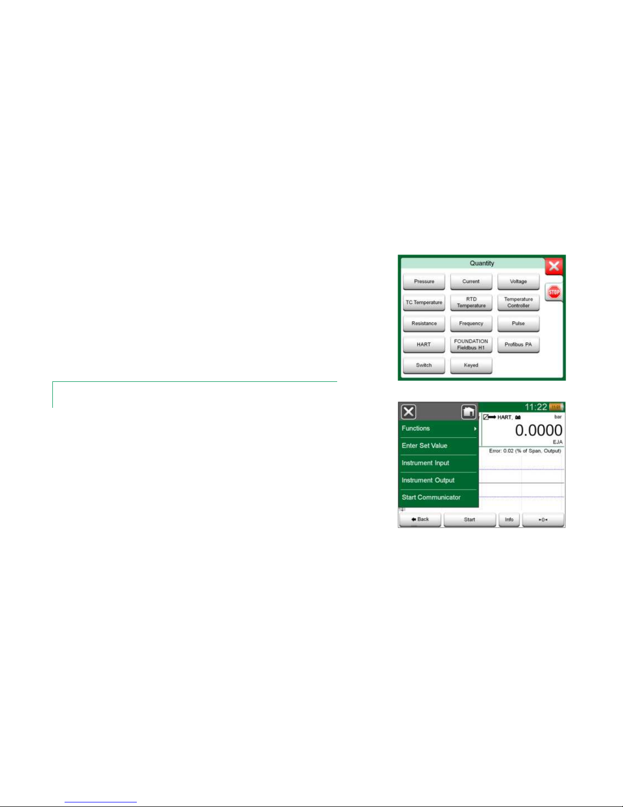
Calibrating Instruments - Calibrating an Instrument Using MC6 Workstation 43
ABOUT FIELDBUS AND HART DEVICE SPECIFICS
Detailed information of fieldbus and HART device specifics are discussed in
Part 7, Communicator. However, here are some hints on where fieldbus and
HART device related features appear in Documenting Calibrator.
Adding fieldbus and HART Instrument to MC6 Workstation's database
When adding a fieldbus instrument or a HART instrument's digital output to
MC6 Workstation's database, select HART, FOUNDATION Fieldbus H1 or
Profibus PA as the output quantity. See adjacent picture and note below.
See also chapter Digital Communication and MC6 Workstation on page 48.
Note.
For HART instrument's analog output, select Current as the output quantity.
Additional utilities during calibration
During Calibration, MC6 Workstation's menu has additional menu options available: For both HART and fieldbus instruments: a possibility to invoke the communicator to edit instrument data and when needed, start a HART trim method.
For fieldbus instruments, an additional menu option for trimming the instrument
is also available.
Documenting Calibrator's quantity selection window
Menu in Documenting Calibrator when
calibrating a HART instrument.
Page 52

44 MC6 Workstation, User Manual – Part 5, Documenting Calibrator
GROUP CALIBRATION
MC6 Workstation's Group Calibration allows you to simultaneously calibrate
several Instruments/Functions. This is practical, e.g. when calibrating Instruments/Functions that are part of a loop, or when input generation takes time
(temperature) and there are several devices to be calibrated.
Note.
Switches are not supported in group calibration. All other type
of instruments/functions can be included in a group.
COLLECTING INSTRUMENTS/FUNCTIONS FOR GROUP CALIBRATION
To start collecting Instruments/Functions to a group, open the Documenting
Calibrator's Instrument List window: Open the menu and tap on Create New
to see the sub-menu where Grouping can be activated. See adjacent picture.
Collect Instruments/Functions by tapping on each Instrument/Function you want
to add to the group. In the Instrument Overview window, tap on the Add to
Group button. See picture below. The Hardware Focus Indicator is on the Add
to Group button.
Hardware Focus Indicator on "Add to Group" button.
Activating a Group.
Instruments/Functions selected in a group have
blue background in the Instrument List.
Page 53

Group Calibration - Calibrating a Group 45
EDITING A GROUP
By default, the Instruments/Functions are calibrated in the order they were included
in the group. However, the Instrument Overview window's menu includes a pos-
sibility to sort the group according to your own needs. The same menu also includes a possibility to cancel the Group or to remove the current Instrument/Function from the Group (in the Instrument menu option's sub-menu).
Menu item Instrument Order, Optimize sorts the items automatically so the
first instrument to be calibrated has the smallest/lowest calibration point of all
instruments in the group.
Notes.
The Instrument Overview window's buttons change when Group Calibration is active. In addition to Add to Group button you have browse buttons for browsing through the Instruments/Functions selected to the Group. Instrument Settings and Calibration Results are
moved to the Instrument Overview window's menu.
Sorting the Instruments/Functions in a group.
CALIBRATING A GROUP
Calibration is started the same way as the calibration of a single Instrument/
Function; by tapping the Instrument Overview window's Accept button. The
Calibration window opens displaying the Group's first Instrument/Function.
The text in the Calibration window's Info button has changed to indicate which
Instrument/Function is currently shown in the window (1/3 in the adjacent picture). The functionality of the button is the same:
Before starting, check the settings in the Calibration window's menu:
Settings include the possibility to show the Function Name in the Title Bar. It
may be a more descriptive text when calibrating a group of Instruments/Functions belonging to a loop.
In Group Settings you can define when the Instrument Overview (Instrument
Info) window appears during Group Calibration.
Settings and Group Settings
Page 54

46 MC6 Workstation, User Manual – Part 5, Documenting Calibrator
GROUP SETTINGS
In Group Settings you can define two things:
Calibration Point Sequence, i.e. how the calibration points are run
through. More details below.
When the Instrument Overview (Instrument Info) window appears dur-
ing Group Calibration.
Calibration Point Sequence options:
By Group: Suitable when all instruments selected into the group have
the same input span. The instruments may have different amount of calibration points as long as the input span is the same.
By Value: The instruments selected into the group may have a span of
any size. The only important thing is: The group's first instrument has
to have the smallest/lowest calibration point of all instruments in
the group. When necessary, use the sorting tool presented in chapter
Editing a Group on page 45.
PERFORMING THE CALIBRATION
The actual calibration is done from point to point similarly as a non-Group Calibration. You may change the default calibration order of Instruments/Functions
by tapping the Info button (see adjacent picture) and selecting another Instrument/Function by browsing the Instrument Overview window.
After all points of all Instruments/Functions are done, the calibration result pages open one by one and you have the chance to save (or not) the calibration
results for each Instrument/Function in the Group.
When the results of all Instruments/Functions are saved (or not), MC6 Workstation returns to the Calibration window. Now you may do another calibration
run or return to the instrument list to, e.g. remove Instruments/Functions from
the Group that did pass in the As Found test and leave the Instruments/Functions in the Group that require As Left calibration.
Group Settings Window.
Note.
Remember to change connections (if necessary) when the Instrument/Function changes during the Group calibration.
Info button highlighted.
(2nd instrument of a group of three @ 75 °C)
Hint.
Examples of Instruments/Functions suited for Group Calibration:
• A measurement loop, including a temperature transmitter,
a local temperature indicator and a temperature indicator
in the control room.
• A set of temperature sensors calibrated simultaneously
using, e.g. a dry block.
Page 55

Calibration Results - Deleting Calibration Results 47
CALIBRATION RESULTS
Once an instrument has been calibrated, you may view saved calibration results
as follows:
When viewing the Instrument Overview Window, select the Calibra-
tion Results button.
The most recent saved calibration is presented. If you want to see older results,
open the menu in Calibration Results window and select Results History.
Then a list presenting all saved results opens. See adjacent picture.
To separate calibration events from each other, they have a different shades of
gray background colors. If the instrument's settings have changed, a field with
blue background is seen. Tap it to see the settings as they were before that
date/time.
Calibration results history window
Note.
Saved calibration results cannot be edited.
DELETING CALIBRATION RESULTS
When viewing the results of a calibration, you may delete the currently viewed
result (menu option Delete This Result) or remove all results related to current
instrument (menu option Delete All Results).
You may also remove all results related to current instrument in Results Histo-
ry window: Select menu option Delete All Results.
Warning!
Once the results are deleted, there is no way to retrieve
them.
Page 56

48 MC6 Workstation, User Manual – Part 5, Documenting Calibrator
DIGITAL COMMUNICATION AND MC6 WORKSTATION
With this feature, you may add instrument data to MC6 Workstation from Instruments using Digital Communication:
HART® instruments,
FOUNDATION Fieldbus H1tm instruments and
PROFIBUS PA
tm
Instruments
All you need is connect the instrument to MC6 Workstation, select a communication protocol and receive data of the Instrument using Digital Communication
to MC6 Workstation's Instrument Data. No error prone manual entry of Instrument Data.
MC6 Workstation has pre-entered default mappings (which Digital Communication Instrument field goes to which field in MC6 Workstation) but you may customize the mapping for each instrument model you use.
Notes.
Utilizing this feature requires that your MC6 Workstation has
the Documenting Calibrator option as well as the option to
communicate with the smart instrument type (Fieldbus option)
you want to add to MC6 Workstation's instrument data.
You may easily populate CMX's Instrument database by first
mapping instrument data to MC6 Workstation and then transferring the instruments to CMX.
More of Instrument's utilizing Digital Communication can be
found in Part 7 of this manual.
GETTING AND EDITING MAPPED DATA
PREPARATIONS
The data mapping can be done to a new instrument or to an existing instrument
in MC6 Workstation. The Instrument's Output has to be one of the following:
Current (measurement),
HART®,
FOUNDATION Fieldbus H1tm or
Profibus PAtm.
Note.
With Current Measurement as the Instrument's Output, the
communication is available for the HART transmitter found in
address 0 only.
Page 57

Digital Communication and MC6 Workstation - Getting and Editing Mapped Data 49
GETTING DEFAULT MAPPINGS
On any of the instrument data pages, open the menu and tap Get Mapped
Values. Then MC6 Workstation starts reading data from the connected instru-
ment to MC6 Workstation's Identification and Device fields, according to Mapping settings.
That's all you need to do, provided the mappings suit your needs. If not, see
chapter Customizing the Mappings below.
However, you should anyhow always check all the instrument settings after the
data is read, before continuing with your work.
Note.
For HART® Instrument's, the input setting is also read from the transmitter. For other instruments, you need to manually add the Instrument's input data.
Mapping menus on instrument pages.
CUSTOMIZING THE MAPPINGS
The menu option, Mapping, has in its submenus options on how to define general mappings on protocol level (HART, FOUNDATION Fieldbus H1 or Profi-
bus PA) and also default mappings on device model level.
MC6 Workstation uses the Protocol Defaults if no default mappings are defined for the connected device model. If Device Model Defaults exist for the
connected device model, they are used instead of Protocol Defaults.
In the adjacent picture you can see a sample of the mappings. The left side lists
the fields in MC6 Workstation (target fields) and the Mapping Mode of the field
(Generic in all cases of the sample picture). The right side lists the value and
name of the field in the device.
Tap on one of the buttons to edit the mapping. You may also add new mappings using the New button, the button with blank sheet and a star on its upper
right corner. New mappings are defined similarly as existing mappings are edited.
Sample of default mappings for HART protocol.
Page 58

50 MC6 Workstation, User Manual – Part 5, Documenting Calibrator
Creating a new mapping or editing an existing mapping is done in a window like
the one to the right.
Target Field is the field in MC6 Workstation, Value is the field and its value in
the connected device. Mapping Mode defines how the mapping is done.
Generic, gives you a list of protocol's common fields.
Text, assigns a fixed text to the selected MC6 Workstation field.
DD Field, gives you a list of all fields etc. available in the device model's
Device Description. Note that this option is not available for the Protocol Defaults, only for Device Model Defaults.
Notes.
It is possible to map the same transmitter field into several MC6 Workstation fields. In the picture on previous page, device's Tag is mapped both to Position ID and Device ID in MC6
Workstation's instrument data.
When adding or editing mapping, the target fields that are already being used are disabled
(gray).
When you change the mapping, it will be saved as the default mapping for future use.
After changing the mapping, you need to read the data again using the Get Mapped Data
menu command.
Generic Fields when Mapping Mode is "Generic".
Sample of default mappings for HART protocol.
Note.
You can remove a single mapping line by opening it and touching the “Trash Can” icon.
Text editing when Mapping Mode is "Text".
Page 59

Things discussed in this part:
An introduction Data Logger option and its capabili-
ties.
How to configure and start a Data Log.
How to view, save and delete Data Log results.
How to transfer Data Log results to a personal com-
puter (PC).
Part 6
DATA LOGGER
Page 60

52 MC6 Workstation, User Manual – Part 6, Data Logger
GENERAL
The Data Logger is an optional tool that allows you to collect data with MC6
Workstation. If the Data Logger option is purchased, the collected data may
then be viewed, transferred to a personal computer (PC) and printed using a
utility called Beamex MC6 Workstation Data Log Viewer. It is shipped together with MC6 Workstation.
If your MC6 Workstation does not have the option installed, the Data Logger
icon in MC6 Workstation's Home View is disabled.
If applicable, open the main configuration window of the Data Logger by tapping
on the Data Logger icon in MC6 Workstation's Home View (see adjacent picture).
Data Logger supports logging up to nine measurement/generation/simulation
channels at the same time. However, the amount of available measurements/generations/simulations depends on how your MC6 Workstation is
equipped.
The window on this page's lower right corner is the Data Logger's main configuration window when no data log channels have been configured. Typically, you
see some previously configured channels, since MC6 Workstation remembers
the latest data log configurations.
Home View with Data Logger selected
Main configuration window
Page 61

Doing a Data Log - Configuring 53
DOING A DATA LOG
CONFIGURING
In the main configuration window: Tap on one of the numbered areas to configure a channel.
Each channel have individual configuration pages as follows:
A page for defining the measured/generated/simulated quantity and its
additional settings.
Another for defining the range of the graph, giving the measure-
ment/generation/simulation a descriptive name (optional) and selecting
plot color.
A third page is available for measurement channels only: You may de-
fine a trigger that invokes the Data Log. When triggering is configured, a
symbol indicates it. See channel three in the adjacent picture.
Remember to check/edit the general settings of your Data Log. Tap on the area
in the lower left corner of Data Logger's main configuration window. There you
may, among other things, define how the logging is performed, what value is
saved and the duration of the logging.
SAVING AND OPENING CONFIGURATIONS
In addition to MC6 Workstation remembering the latest Data Log configurations,
you may save useful configurations for future use. Saving and opening previously saved configurations is available in the menu of Data Logger's main configuration window.
Three configured channels in
main configuration window.
Note.
For pressure measurements:
The main configuration window's menu includes a possibility to
zero gauge pressure modules. Zeroing is also possible in
channel setup windows (when applicable).
Page 62

54 MC6 Workstation, User Manual – Part 6, Data Logger
STARTING THE DATA LOG
Start the Data Log by tapping on the red "Record" button in the main configuration window's lower right corner. The button changes to a black "Stop" button
allowing you to interrupt you Data Log, when necessary.
The actual start of Data Logging depend on general settings as follows:
If you have defined a delay in the Delayed Start field, an hour glass with
a down counter appears for as long as the delay requires. The delay
may be either a defined wait time, e.g. 5 minutes, or a specific time of
the day, e.g. 5:15 PM.
If your Logging Method is "Key Press", a camera button appears for
you to take "snap shots" of the measurements.
When the possible delay defined in general settings has expired, possible triggers defined for individual channels delay the start of the Data Logging. Any
channel that trigs, starts the Data Log. See also note below.
You may change the view from the main configuration window to the graph view
(lower picture on this page) and back using the button to the left of the Record/Stop button.
Notes.
If, in general settings, the Logging Method is "Key Press", none of possible triggers defined
for individual channels are valid. The snap shot is saved immediately each time the snap shot
button is tapped on.
A generation/simulation value may be changed during the data log as follows:
In the main configuration window, tap on the channel where a generation/simulation is configured. In the opened window, locate the output value field and tap on it to edit the numeric value.
Counting down the delay
Graph view during Data Log.
Snap shot button
Page 63

Doing a Data Log - Viewing and Saving or Deleting the Results 55
VIEWING AND SAVING OR DELETING THE RESULTS
When Data Logging is finished, or stopped, the results are shown on three pages: general information page, graph page and a table of numeric results. If the
table of numeric results is large, use the scroll buttons or the scroll bar to see
hidden rows/columns.
All pages include a possibility to either save or delete the Data Logging results.
When saving, you have the possibility to give a descriptive name to the Data
Logging results. MC6 Workstation automatically adds date and time to the Data
Logging results.
Results Preview
VIEWING SAVED DATA LOG RESULTS
If you have saved Data Logs, they may be viewed as follows:
From the menu of the Data Logging's main configuration window. Select
menu option View Data Log Results.
Each saved Data Log result has the time/date it was saved and the entered
result name on the first row in bold font. On the second row you can see information of Data Log's size and possibly the name of the configuration used for
doing the Data Log.
Note.
When viewing the list of saved Data Log results, the menu includes the possibility to Delete
All saved Data Log results. If you select one of the existing results for viewing, the menu includes a possibility to either Delete or Rename the viewed Data Log results.
Data Log Result list.
Page 64

56 MC6 Workstation, User Manual – Part 6, Data Logger
TRANSFERRING DATA LOG RESULTS TO A PERSONAL COMPUTER
Beamex MC6 Data Log Viewer (executable file: "MC6DataLogViewer.exe")
reads data log results to a Personal Computer. The software works in any 32 bit
or 64 bit Windows® 7 … Windows® 10 operating system. Installation software
for Beamex MC6 Data Log Viewer is downloadable from Beamex's web site
https://www.beamex.com. Look for Download Center.
Before you read data from MC6 Workstation, you must connect MC6 Workstation to your PC using the USB cable provided. Then install the driver as presented in Part 1, Introduction, chapter USB Communication Driver.
After the driver is installed, the software can be used for downloading the results from MC6 Workstation and viewing the results. The data can be saved in
viewer's native format (.LG6) or saved as CSV files. The latter format can easily
be imported into spreadsheet software.
Screen shot of Beamex MC6 Data Log Viewer
Page 65

Things discussed in this part:
An introduction MC6 Workstation's Communicator
and how it can be started.
How to connect to an instrument capable of digital
communication.
Instructions on how to quickly select a varia-
ble/parameter for use in Calibrator, Documenting Calibrator or Data Logger.
How to edit instrument parameters.
About how to trim a Fieldbus/HART instrument.
Part 7
COMMUNICATOR
Page 66

58 MC6 Workstation, User Manual – Part 7, Communicator
GENERAL
MC6 Workstation's Communicator option allows you to connect to the following Instruments utilizing Digital Communication:
HART® instruments(*
(https://www.fieldcommgroup.org/)
MC6 Workstation can be used as a primary or secondary master of a
segment.
FOUNDATION Fieldbus H1tm instruments
(http://www.fieldbus.org/).
MC6 Workstation is seen as a guest device (visitor) and, when necessary, as a Link Active Scheduler (LAS, segment's master device).
PROFIBUS PA
tm
Instruments
(https://www.profibus.com/).
MC6 Workstation takes the role of PROFIBUS Master when connected
to a PROFIBUS segment.
When Communicator is started, a list of communication protocols available for
MC6 Workstation is shown. See lower picture to the right.
Notes.
Each communication protocol is a separate option in MC6 Workstation, so all protocols are not
necessary enabled in your MC6 Workstation.
This manual is not an introduction to HART and Fieldbus instruments. Get the know-how and
terminology from books dedicated to HART and Fieldbus instruments and technology.
The Communicator's user interface may include text in another language than what MC6
Workstation's user interface language setting is. This happens when the language of the instrument's fields etc. differ from MC6 Workstation's.
*) MC6 Workstation supports HART instruments using HART Protocols 5, 6 and 7.
Home View with Communicator selected
Communication protocols.
Page 67

General - Warnings 59
Communication may also be started from the following main functions in MC6
Workstation:
Calibrator,
Documenting Calibrator and
Data Logger.
Depending on active/inactive options, some communication protocols may be
disabled (grayed).
MC6 Workstation's Communicator is primarily meant for viewing and editing
the configuration of Digital Communication Instruments. However, when invoking communication from Calibrator, Documenting Calibrator or Data Logger,
you most likely plan to select a Variable or Parameter (e.g. Primary Value) for
calibration or data logging instead of doing full configuration for the instrument.
MC6 Workstation, of course, supports this functionality too.
Selecting a communication protocol in Calibrator,
Documenting Calibrator and Data Logger.
WARNINGS
Configuring/calibrating an instrument that is part of a live segment is possible in HART
and FOUNDATION Fieldbus only. When working in a live segment, first make sure, the
control loop the instrument is part of is set to manual. Follow the guidelines available in
the instrument's own manual.
Beamex cannot be held responsible for any damages caused by connecting MC6 Workstation to a live factory fieldbus segment.
Using MC6 Workstation to change the parameters of an
instrument may result in discrepancies: A fieldbus host
control system may mirror all instrument parameters in its
permanent database. In such a case, when returning an
instrument with changed parameters to a live segment,
ensure that the parameters are also available in the control
system's permanent database. Also verify that the new parameters do not result in an unstable control loop.
Page 68

60 MC6 Workstation, User Manual – Part 7, Communicator
CONNECTIONS
When communicating with Digital Communication Instruments, the connection
differs depending on whether MC6 Workstation's internal power supply is used
or not.
The upper picture to the right presents the connections when MC6 Work-
station's internal power supply is used. MC6 Workstation's power supply
can safely provide supply power to a single instrument. If connecting to a
HART/fieldbus segment containing several instruments, consider using an external power supply as presented further on.
The lower picture to the right presents the connections when an external pow-
er supply is used. Then, to ensure communication, there may be need to include an external resistor (250 ohm for HART and 50 ohm for fieldbuses). However, when using a fieldbus compliant power supply, there is no need for an
external resistor. See also warning below.
Notes.
The connection between MC6 Workstation and the instrument/fieldbus may be done using pair
of standard measurement cables. However, when using longer connecting cables there may
be need for fieldbus terminators.
Warning!
When working in PROFIBUS PA: Do not connect two master devices (e.g. MC6 Workstation, a Field Communicator or a control system) at the same time to the same segment! They clash and make the fieldbus segment unstable. Remove the instrument to
be calibrated from the live segment for calibration.
See also Warnings on page 59.
Using MC6 Workstation's internal power supply.
Using an external power supply.
Fieldbus
or HART
Instrument
Power
Supply
Resistor
Fieldbus
or HART
Instrument
Page 69

Selecting the Instrument - List of Found Devices 61
SELECTING THE INSTRUMENT
When a communication protocol is selected, a window opens for choosing
whether MC6 Workstation's internal 24 V supply is used or not. When using an external supply, ensure communication by using either a Fieldbus/HART
compliant power supply or add a suitable resistor between the power supply
and the fieldbus. See chapter Connections on page 60 and consult your power
supply's manual.
There is also a button for editing/checking the Protocol Settings. The default
settings should apply, so do not make changes unless you are sure. Consult
the fieldbus instrument's manual, in case of communication problems.
Supply voltage setting
LIST OF FOUND DEVICES
When continuing, MC6 Workstation searches (monitors) for connected instruments and a window with a list of found devices opens. The window also includes a "refresh" button (two "rotating arrows") to retry the search for connected instruments. The button with the cogwheels allows you to quickly edit the tag
and address for the listed instruments. When edit mode is on, the button backgrounds change to blue.
When not editing tag and address, select the instrument for calibration by tapping on its name in the displayed list. Then MC6 Workstation uploads the instrument's data into its memory and when ready, displays it.
Note.
If MC6 Workstation does not have the Device Description file for the selected instrument, a
window opens informing you of the situation. Look for new Device Description files at
Beamex's web site: https://www.beamex.com. Install a downloaded Device Description file
using the Device Description Installer software available at Beamex's web site:
https://www.beamex.com. Look for Download Center.
A list of found devices.
IMPORTANT!
When the calibrator is monitoring a fieldbus/HART segment, DO NOT disconnect/reconnect the calibrator to/from
the segment. The segment may become unstable.
Page 70

62 MC6 Workstation, User Manual – Part 7, Communicator
ABOUT INSTRUMENT PARAMETERS
INSTRUMENT PARAMETERS IN GENERAL
This chapter briefly presents how Blocks, Records and Parameters of Digital
Communication Instruments are viewed in MC6 Workstation and how you may
browse through them. Elements seen while viewing/configuring an instrument:
Blocks and Records have yellow background where the upper right cor-
ner is folded. They may contain sub-blocks, sub-records, editable parameters and read-only parameters. Tap on the block/record to see its contents.
Different types of Parameters:
o Editable Parameters have gray background. They may be numeric,
text, single select, multi select or date fields. Tap to edit the field data.
o Read-Only Parameters are data that you may view/read but they
cannot be edited. They have gray background with a "lock" in the upper right corner.
o Value Parameter is actually a special case of the Read-Only Param-
eter. The value is a result of a measurement and cannot be edited,
but it can be opened for viewing and selected for use in the Calibra-
tor, Documenting Calibrator or Data Logger. Value Parameters
have green background. See also note to the right and hint below.
o Methods look like parameters, but are actually automated proce-
dures for e.g. calibration in HART instruments. For details, see instrument's user manual.
Hint.
Since value parameters are often of high interest, the menu contains a possibility to view value
parameters (measurable variables) only.
Blocks and Parameters, an example view.
Notes.
If you select a Value Parameter and you started communication from the Communicator, the value is taken into use in
Calibrator. If communication is started from any other supported main function, e.g. Data Logger, the chosen Value Parameter is taken into use in that particular main function.
Page 71

About Instrument Parameters - Calibrating or Data Logging HART instruments 63
CALIBRATING OR DATA LOGGING HART INSTRUMENTS
Usually, when calibrating or logging, you need to locate a Value Parameter, a
Process Variable, in the HART instrument's instrument data. Remember that
Value Parameters have green background.
Unfortunately the structure of data and naming conventions in HART instruments vary between different makes and models. Thus there is no single path
from selecting the instrument in MC6 Workstation to locating the parameter.
Refer to your instrument's manual to find the blocks where the parameters are
located. Use the information presented on the previous page to browse the instrument data. See also hint on previous page.
Once the parameter is located, tap on it. In the opened window (a picture similar to the one at bottom right): Tap the Accept button to start calibrating or logging that parameter.
Example of a variable list in a HART Transmitter
CALIBRATING OR DATA LOGGING FIELDBUS INSTRUMENTS
This is a quick guide for selecting a FOUNDATION Fieldbus or Profibus PA
instrument's Parameter for calibration/data logging. If you want to make more
extensive configurations, refer to chapter About Instrument Parameters on
page 62 and the manual of your instrument at hand.
1. First you must select either FOUNDATION Fieldbus or Profibus PA as
your communication protocol and select the instrument as presented in
chapter: Selecting the Instrument on page 61.
2. Transducer is the typical name of the Block (folder) where measurement parameters are located. When applicable, tap on it. Note that the
Block name depends on the instrument, so when uncertain, refer to
your instrument's user manual.
3. Browse the opened list of blocks, records and parameters. Tap the one
you select for use in MC6 Workstation, e.g. Primary Value.
4. Accept the selection by tapping on the Accept button.
Accepting a parameter.
Page 72

64 MC6 Workstation, User Manual – Part 7, Communicator
EDITING PARAMETERS
With "editing parameters" we mean changing any editable parameter in the
instrument's memory, e.g. selecting the type of process connection fitted to the
instrument.
Editing a Parameter is started by tapping on it. A window opens for editing the
data. The type of window depends on the type of parameter that is edited, e.g.
a selection list, text or a numeric value.
When editing a stand-alone parameter (stand-alone in this context means it is
not part of a record that contains several parameters), the edited value is sent
to the instrument immediately when the accept button is tapped on.
In a HART instrument: If a parameter is part of a record, i.e. several parameters together as in the example picture to the right, each parameter may be edited separately. However, the edited values are not sent to the instrument until
the accept button of the record window is tapped on. Prior to sending, edited
parameters have a blue background.
See also Warnings on page 59.
Example of a record: Sensor Information.
Notes.
This manual explains how the parameters are accessed using
MC6 Workstation. For detailed information of instrument data,
refer to the manual of the instrument itself.
Beamex cannot be held responsible for any damages caused
by changing instrument parameters.
Page 73

About Instrument Parameters - Trimming a Fieldbus instrument 65
TRIMMING A FIELDBUS INSTRUMENT
Trimming a FOUNDATION Fieldbus or a Profibus PA instrument can be initiated from the Documenting Calibrator, provided the relevant communicator
option is enabled and the instrument's Device Description contains information
of parameters needed for trimming. See picture to the right.
Menu option Start Trimming opens a window similar to the lowermost picture
to the right. The list of Blocks and Parameters depends on instrument's Device
Description. The lower part of the window has areas were the instrument's input
(1) and output (2) readings are shown.
Refer to the instrument's user manual for detailed information on how the trim
procedure progresses. Usually you first set the Mode Block to Manual and then
start editing the other data.
The actual trim is done by tapping on Trim 0 % or Trim 100 % values after a
valid input signal is generated/simulated/measured. A window for editing the
numeric value opens. The window includes a button for copying the input reading as the correct value.
Copy button
Notes.
Some fieldbus instrument manuals and user interfaces use the term "calibration" when they
actually mean a trimming procedure. Be aware of this pitfall when trimming a fieldbus instrument.
Be careful during the trimming procedure. Follow the instructions in the instrument's user
manual. Skipping a step in the procedure may result in an unsuccessful trim.
Menu in Documenting Calibrator when
calibrating a fieldbus instrument.
Fieldbus instrument's trimming window, example.
Page 74

66 MC6 Workstation, User Manual – Part 7, Communicator
TRIMMING A HART INSTRUMENT
Trimming a HART instrument can be started from the Documenting Calibrator's menu and also from other MC6 Workstation's main functions where HART
communication may be started. When calibrating a HART instrument, the Documenting Calibrator's menu contains the option HART Communicator.
When trimming, refer to the instrument's user manual to locate and start a
trimming method, either for the analog or the digital signal / sensor. When the
method is located follow its instructions. At some point during the method, you
need to apply an applicable input signal. See lowermost picture to the right.
If the trimming procedure was invoked from Documenting Calibrator, the
lower part of the window has areas were the instrument's input (1) and
possibly also the output (2) readings are shown. Use the input signal area to check what the correct reading is.
If the trimming procedure was invoked from another MC6 Workstation
main function, e.g. Communicator, tap on either of the areas reserved
for calibrator readings and select a suitable Quantity for measurement.
In both cases: When the input signal is as required, enter the correct value to
the numeric field that is made available at this stage. Optionally, use one of the
Copy buttons seen on the right side of the window to copy the reading available
in the areas reserved for calibrator readings.
To finalize the trim, continue as the trim method describes on MC6 Workstation's display.
Notes.
Just as in fieldbus instruments, the user interface and manuals of HART instruments are
sometimes using the misleading term "calibration" although it is actually a trim that is performed.
Be careful during the trimming procedure. Follow the instructions in the instrument's user
manual. Skipping a step in the procedure may result in an unsuccessful trim.
Sensor trim method.
Trim method in progress.
Note.
Typically, the correct order for trimming is: digital output first,
then analog output.
Page 75

HART Device Description Specifics - General 67
HART DEVICE DESCRIPTION SPECIFICS
GENERAL
MC6 Workstation supports the use of three kinds of Device Descriptions for
HART instruments:
Device Specific, i.e. custom Device Descriptions for the HART device
at hand, available in MC6. Full instrument data is available.
Generic, i.e. a library of common Device Descriptions applying to most
HART devices. Only a standard set of instrument data is available for
instruments containing additional, device specific data.
Basic View, a simplified Device Description available in MC6 Work-
station. It presents the instrument's value parameters only in addition to
basic Device Setup and Process Variable Settings.
The default setting of Active Device Descriptions in MC6 may be defined in
MC6 Workstation's Settings (see picture on the top right). Also: When connecting to a HART device and selecting the supply, the tools button on the right
opens HART settings where you can select the Active Device Descriptions (see
picture at the bottom right). This is available in Calibrator, Documenting Cali-
brator, Data Logger and Communicator.
Window for Selecting a Device Description for Use.
HART in MC6 Workstation's Settings.
HART Tools elsewhere
(note the Hardware Focus Indicator).
Page 76

68 MC6 Workstation, User Manual – Part 7, Communicator
BASIC VIEW
MC6 Workstation's Basic View simplifies the use of HART instruments, since all
that is seen are the instrument's value parameters in addition to basic Device
Setup and Process Variable Settings. Select any value parameter you like for
calibration, data logging etc.
Example of HART Basic View.
The pictures to the right present fields that are available for editing in Device
Setup window (top right) and Process Variable Settings window (bottom right).
Note.
HART trimming is not supported when using MC6 Workstation's Basic View. Use another Device Description when trimming a HART instrument.
Example of a HART Device Setup Window.
Example of a Process Variable Settings Window.
Page 77

Managing Smart Transmitter Configurations - General 69
MANAGING SMART TRANSMITTER CONFIGURATIONS
GENERAL
Beamex offers a possibility to manage smart transmitter configurations using
MC6 Workstation and a free tool for personal computers: Beamex MC6
Fieldbus Configuration Viewer. If applicable, the configurations may also be
sent to Beamex CMX Calibration Software, as linked documents for a position.
Note.
To be able to utilize this feature you need to have one or more
of the necessary options installed (HART®, FOUNDATION
Fieldbus H1tm or Profibus PAtm).
TOOLS IN MC6 WORKSTATION
SAVING CONFIGURATIONS
When connected to a smart transmitter, open the menu to locate the Configuration, Save As menu option. When selected, MC6 Workstation downloads all
configuration data and after downloading it, prompts you to give the configuration a name. The default name is the transmitter's Tag name.
This feature is handy especially for customers that have analog DCS system
and HART transmitters in the field. They can use this functionality to create a
database with all the settings of their transmitters. If a transmitter breaks, all
settings are stored in MC6 Workstation (alternatively on a PC's hard disk) for
easy configuration of the new transmitter replacing the broken one.
Note.
Please note that a saved configuration file cannot be written from MC6 Workstation back to a
transmitter.
Configuration menu open.
Page 78

70 MC6 Workstation, User Manual – Part 7, Communicator
VIEWING/MANAGING CONFIGURATIONS
Opening a list of saved configurations can be opened anywhere in Communicator. Open configurations option can be seen in the picture on the previous
page and on this page where no protocol is selected yet.
Selecting Open Configuration shows a list of saved configurations. The list
shows the following information of each saved configuration file:
The name of the file,
Manufacturer / Model,
Date / Time when saved and
Protocol name.
You can sort the list of configurations according to your own needs with the help
of the sorting tools available in the menu. Tap on a configuration to view the
saved configuration data. Note that the data cannot be edited.
Configuration options in protocol selection window.
BEAMEX MC6 WORKSTATION FIELDBUS CONFIGURATION VIEWER
Beamex MC6 Fieldbus Configuration Viewer is a free tool for personal computers with Windows® operating system. Download the Configuration Viewer
software from Beamex's web site: https://www.beamex.com. Look for Down-
load Center.
UPLOADING CONFIGURATIONS
With Beamex MC6 Fieldbus Configuration Viewer, you can:
Read configuration files from MC6
View the configuration files
Save the configuration files in PC (e.g. proprietary *.fc file).
Print the configuration files
LINKING CONFIGURATIONS TO CMX
CMX includes a possibility to link documents to Positions/Devices etc. Use this
feature to link the *.fc files to CMX. Double click the link to open it in the viewer.
Beamex MC6 Fieldbus Configuration Viewer.
Page 79

Things discussed in this part:
How to configure MC6 Workstation to suit your own
needs
Briefly about re-calibrating/adjusting MC6 Workstation
Optional security tool
Part 8
SETTINGS
Page 80

72 MC6 Workstation, User Manual – Part 8, Settings
SETTINGS
This main function allows you to configure MC6 Workstation according to your
own needs and also, recalibrate MC6 Workstation. The following settings/configurations are available:
Language for selecting user interface language.
About. Information about installed modules, firmware options etc.
Power Management for defining auto-off delays and display brightness.
Sound Volumes for setting volumes for different sounds MC6 Work-
station emits.
Date & Time, including Time Zone selection and activating Daylight
Saving Time. See also chapter Optional Security Tool on page 73.
Regional Settings for setting local net frequency and default values.
See also chapter Optional Security Tool on page 73.
Owner for entering owner information, shown in Home View.
Controller Presets. Enabled if you have purchased controller commu-
nication options. More in Part 9, Additional Information.
Maintenance for re-calibrating/adjusting MC6 Workstation and setting
calibration date. Also, the possibility to align the Touch Screen. Im-
portant: Use a stylus when aligning the Touch Screen.
Documenting Calibrator. Settings related to instrument calibration, e.g.
is "Save as Both" allowed ("Save as Both" means a single calibration
run may be saved both as As Found and As Left calibration.)
HART, FOUNDATION Fieldbus and Profibus PA for defining commu-
nication parameters to Digital Communication Instruments.
Network for setting local area network parameters. Future expansion.
Supervisor. Part of Security Plus option. Read more in chapter Op-
tional Security Tool on page 73.
Each setting/configuration is self-explanatory once you have familiarized yourself with MC6 Workstation's user interface. Configuration screens often have a
menu option for recalling factory settings.
Home View with Settings selected
and Owner information defined.
Notes.
MC6 Workstation's auto off functionality is disabled in the following cases:
• When charger is connected,
• when adjusting MC6 Workstation's own
measurement/generation/simulation ranges,
• when a data log is in progress and
• when an instrument calibration is in progress.
PIN code for setting MC6 Workstation's calibration date is
2010. PIN code for MC6 Workstation's adjustment is device
dependent and was shipped together with MC6 Workstation.
Page 81

Optional Security Tool - General 73
OPTIONAL SECURITY TOOL
GENERAL
Beamex CMX Calibration Software version 2, revision 2.11 and later include an
optional tool called Mobile Security Plus. It is a tool that enforces security related settings in mobile devices, including MC6 Workstation. For detailed information about Mobile Security Plus functionality, please see CMX User Guide.
The following restriction options are available in Documenting Calibrator's Su-
pervisor Window (for a user defined as Mobile Supervisor in CMX):
None. No restrictions.
Mobile Supervisor's PIN Code or User ID & password. These admin
credentials need to be entered before restricted functionalities in Documenting Calibrator are allowed.
Blocked. Restricted functionalities are blocked, i.e. not allowed at all, in
Documenting Calibrator.
APPLIED RESTRICTIONS
The following Documenting Calibrator functionalities are either restricted with
admin credentials or blocked, depending on the setting in Supervisor Window:
Skipping or undoing a calibration point,
Rejecting (exiting) an incomplete calibration without saving the results,
Changing the calibration date and time of a keyed calibration,
Deleting calibration results and
Deleting an instrument with calibration results.
Additionally, Changing Regional Settings, Date and Time require admin credentials.
Supervisor Window.
Calibrator's Message When a
Functionality is Blocked.
Page 82
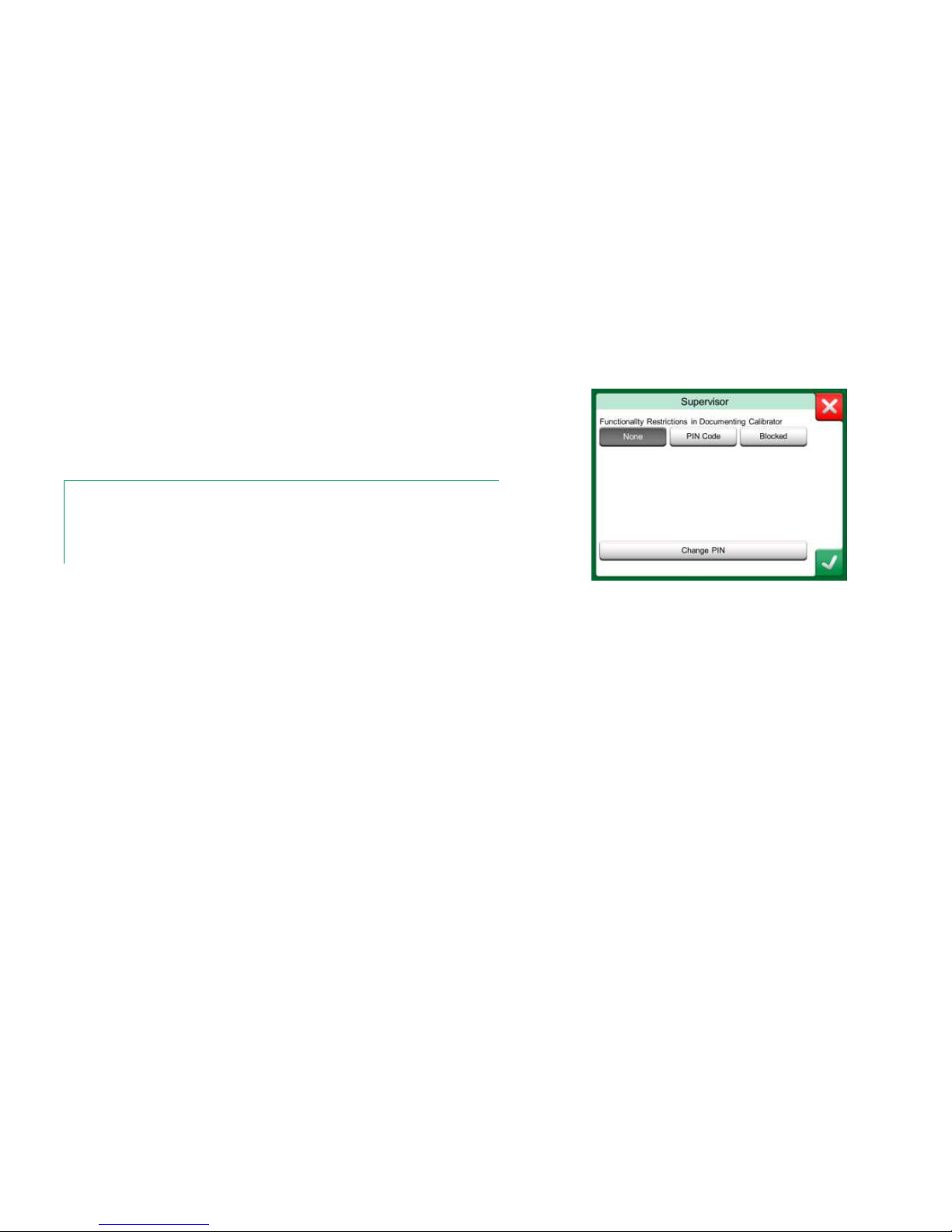
74 MC6 Workstation, User Manual – Part 8, Settings
SUPERVISOR WINDOW
To access the Supervisor window, you need an admin PIN code. If the necessary option was purchased, the PIN code was shipped together with your calibrator. For increased security, you should change the default admin PIN code
to a personal one once you have entered the Supervisor window.
Notes.
When changing the admin PIN code, save the new code in a safe place. There is no way to
retrieve the PIN code.
After three wrong attempts, the admin PIN code is locked. Resetting the PIN Code requires
contacting Beamex support.
Supervisor Window.
Page 83

Things discussed in this part:
How to create custom pressure units,
PRT sensors and transfer functions.
Basic Information on how to connect
external devices like pressure controllers
or temperature blocks to MC6 Workstation.
Part 9
ADDITIONAL INFORMATION
Page 84
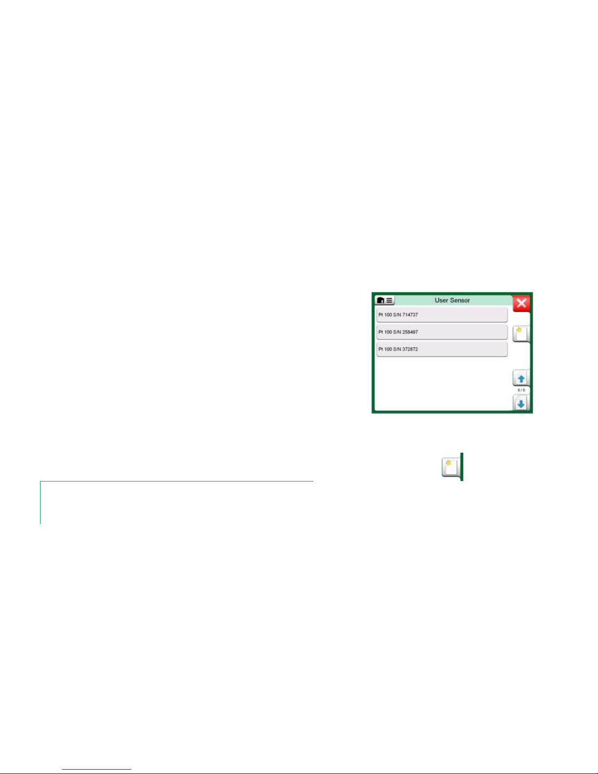
76 MC6 Workstation, User Manual – Part 9, Additional Information
ADDITIONAL INFORMATION
This section contains detailed information of some of MC6 Workstation's more
extensive features. The ones presented here are:
User Defined Pressure Units, on page 77,
User Defined PRT / RTD Sensors, on page 78,
User Defined Transfer Functions, on page 82,
User Defined Steps / Calibration Points, on page 83 and
Controller Communication, on page 84.
Pages, where new user defined items can be created, contain a button as seen
to the bottom right of this page. Add as many items as is needed; more pages
are added when the previous page is full.
Notes.
These features are meant for experienced calibration technicians familiar with calibrators, especially MC6 Workstation.
Deleting a user defined item stops a measurement/generation/simulation that was using it.
An example of a list of custom PRT sensors
entered into MC6 Workstation.
Create New button
Page 85

Additional Information - User Defined Pressure Units 77
USER DEFINED PRESSURE UNITS
Wherever in MC6 Workstation, when you use pressure as the Quantity, you
may choose a pressure unit from a wealth of already available pressure units,
divided into several pages. User defined pressure units may be added to the
subsequent page(s).
In the configuration page, see picture below right, give the unit a descriptive
name, select a Reference Unit and enter the Factor. The Factor is the relationship between the Reference Unit and the custom pressure unit. The Refer-
ence Unit may be any of the pre-entered pressure units available in MC6
Workstation.
When a user defined pressure unit is in use, the unit button displays a warning
symbol (triangle with an exclamation point inside) together with the name of the
user defined pressure unit. See an example below on how a user defined pressure unit is shown in Calibrator. Other MC6 Workstation's main functions display the user defined pressure unit similarly.
User defined pressure unit in Calibrator.
Note.
If you need to enter very small or big number into Factor field, open the menu available in
Soft Numeric Keypad. When applicable, the menu contains a possibility to insert an exponent. This allows entering numbers in scientific notation, e.g. 5.775E-07.
Page 5 of pressure units is reserved
for user defined pressure units.
Configuration page.
Page 86

78 MC6 Workstation, User Manual – Part 9, Additional Information
USER DEFINED PRT / RTD SENSORS
GENERAL
Just as pressure units, MC6 Workstation has a wealth of pre-entered standard
Platinum Resistance Thermometer (PRT) type RTD sensors. They are available
wherever you may select RTD Temperature as the Quantity. However, when
using a PRT sensor as a reference sensor, the available standard sensors
aren't necessary of use. This is because reference sensors often have custom
coefficients in, e.g. their Callendar - van Dusen equation.
After the pages with pre-entered PRT sensors, there is room for user defined
PRT/RTD sensors.
When a user defined PRT/RTD sensor is in use, the sensor button displays a
warning symbol (triangle with an exclamation point inside) together with the
name of the user defined PRT/RTD sensor. See an example below on how a
user defined PRT/RTD sensor is shown in Calibrator. Other MC6 Workstation's
main functions display the user defined PRT sensors similarly.
User defined PRT sensor in Calibrator.
When defining custom sensors, the Sensor Calculation Formula on the first
configuration page is important. It affects what is available on further configuration pages. The following chapters present the use of different formulas.
Notes.
For further information about Sensor Calculation Formulas, refer to literature related to calibrating Platinum Resistance Temperature sensors.
If you need to enter very small or big number into any of the numeric fields, open the menu
available in Soft Numeric Keypad. When applicable, the menu contains a possibility to insert
an exponent. This allows entering numbers in scientific notation, e.g. -5.775E-07.
1st configuration page for defining custom sensors.
Further pages, even the amount of them, depend
on the selected Sensor Calculation Formula.
Sensor Calculation Formula options.
Page 87

Additional Information - User Defined PRT / RTD Sensors 79
CALLENDAR VAN DUSEN FORMULA FOR PRTS
When CvD RTD (R0, A, B, C), i.e. Callendar van Dusen formula is selected,
one additional configuration page is added. See adjacent picture.
Callendar van Dusen formula for PRTs can be defined using one of two equations, each with their own coefficients: A, B and C or alpha, delta and beta (,
and ). Additionally, a constant, R0, is needed to define the sensor.
MC6 Workstation supports the use of the equation using coefficients A, B and C
only. If your PRT's calibration certificate includes coefficients , and , use the
following equations to convert them to A, B and C:
100
1A
,
4
10
B
and
8
0
10
t
C
Converting coefficients , and to coefficients A, B and C.
Example of configuration page for
Callendar van Dusen constant and coefficients.
ITS-90 PRT SENSOR
If your calibration certificate includes coefficients for ITS-90 deviation function
(International Temperature Scale of 1990) PRT sensor, select ITS 90 PRT
(R tpw,…) as the Sensor Calculation Formula. Then you may enter the constant, R tpw, and one or more coefficients: ax, bx …, where the subscript x is 4
to 11, depending on the deviation formula used in the calibration.
If the coefficients in your calibration certificate miss the subscripts, use the following table to find which coefficients you have been given.
Note.
The definition of coefficient notations for the ITS-90 subranges
is described in the NIST Technical Note 1265 "Guidelines For
Realizing the International Temperature Scale of 1990".
Page 88

80 MC6 Workstation, User Manual – Part 9, Additional Information
Calibration ranges, corresponding coefficients and examples of calibration
points:
Calibration Corresponding
Ranges(* Coefficients Example of fixed calibration points(#, °C
Negative (sub-)ranges:
-189 … 0 °C a4, b
4
–189.3442, –38.8344, 0.01
-38 … 30 °C a5, b
5
(
†
–38.8344, 0.01, 29.7666
Positive (sub-)ranges:
0 … 30 °C a11 0.01, 29.7666
-38 … 30 °C a5, b
5
(
*
–38.8344, 0.01, 29.7666
0 … 157 °C a10 0.01, 29.7666, 156.5985
0 … 232 °C a9, b9 0.01, 156.5985, 231.928
0 … 420 °C a8, b8 0.01, 231.928, 419.527
0 … 660 °C a7, b7, c7 0.01, 231.928, 419.527, 660.323
0 … 962 °C a6, b6, c6, d 0.01, 231.928, 419.527, 660.323, 961.78
†)
sub-range 5 is presented twice since it needs to be entered separately both for negative and
positive sides.
Note.
If your calibration certificate include two sets of coefficients.
One for zero current and another for 1 mA current, enter the
latter ones into MC6 Workstation.
*) The range limits in the adjacent list are rounded
and shown as they are on MC6 Workstation's User
Interface.
#)
Not all calibration laboratories necessarily use the
same points. These are for reference only.
When selecting ITS 90 PRT (R tpw,…) as the Sensor Calculation Formula,
the Sensor Range entered in the 1st configuration page defines how many additional User Sensor pages is added to MC6 Workstation. If the range includes
temperatures below zero, the total amount of configuration pages is four:
1. First page for general settings. See page 78.
2. Second page for entering the R tpw constant value.
3. Third page for selecting the deviation formula for negative temperature
sub-range and entering the coefficients (a4 and b4 or a5 and b5).
4. Fourth page for selecting the deviation formula for positive temperature
sub-range and entering the coefficients (a5, a6, a7 … etc.).
When no negative sub-range is included in the calibration, the third page mentioned above is not included and the total amount of configuration pages is
three.
Examples of coefficients a7, b7 and c7.
Page 89

Additional Information - User Defined PRT / RTD Sensors 81
FACTOR
The third way to customize a RTD sensor (not just PRTs but all types of RTDs)
is using the Factor. This applies for sensors with the same relative error
throughout the sensor's span, a sensor with an "offset" in its output.
How to Configure a User Sensor using Factor:
Select a standard Sensor Type. Then enter a Factor that offsets the standard
temperature curve. A simple way of doing it is taking a standard RTD sensor
with a 1 ohm resistance @ 0 °C, e.g. Pt1. Then enter the real resistance
@ 0 °C as the Factor.
Configuration page for Factor
CHECK SENSOR CONVERSION
MC6 Workstation has a possibility to test sensors in the window presenting preentered and custom RTD sensors. The menu has an option: Test Sensor Con-
version.
The adjacent picture presents the first of the Test Sensor Conversion pages.
It allows you to select a sensor, the unit to be used and a possibility to test a
single point. This is handy when you have entered coefficients of a custom sensor and want to test if the coefficients were entered correctly. Enter, e.g. a temperature that is in the calibration certificate and check if the calculated resistance in MC6 Workstation is the same as on the calibration certificate. If yes,
the entered coefficients in MC6 Workstation are correct. If not, check the coefficients you entered.
The lower part of the first page allows you to define step sizes for tables seen
on the second and third page. There you can see the sensor's temperature vs.
resistance correlation (and vice versa) in table format.
Sensor test configuration and
single point test page.
Page 90

82 MC6 Workstation, User Manual – Part 9, Additional Information
USER DEFINED TRANSFER FUNCTIONS
Transfer Functions are available in Calibrator's Scaling Tool and in instrument definitions found in Documenting Calibrator.
When creating/selecting a user defined transfer function, tap on the Transfer
Function button and browse to the User Transfer Function page.
The configuration consists of two (or more) pages as shown in the pictures to
the right of this text. The first page is for general definitions and the second for
entering known transfer function points. If you enter more points than can be
shown on one page, a further page is automatically added.
There are some "rules" on how to enter the transfer function points:
The first point is always pre-entered and the values are not editable.
They are the ranges' 0 % values.
Manually entered points must be in increasing order.
Last point must be exactly or greater than the range's 100 % value.
Also:
The row number is a button. It opens a window where you may delete
the current point or optionally add a row either before or after the current
point.
An added point gets default values: average values of preceding and fol-
lowing point.
1st configuration page.
2nd configuration page.
Page 91

Additional Information - User Defined Steps / Calibration Points 83
USER DEFINED STEPS / CALIBRATION POINTS
These are available for instruments in Documenting Calibrator and also in
Calibrator's Step tool. Use either Calibration Points or Step Definition button
to modify its setting. In the opened window, browse to User Test Points page.
The configuration consists of two (or more) pages as shown in the pictures to
the right of this text. The first page is for general definitions and the second for
entering steps / calibration points. If you enter more points than can be shown
on one page, a further page is automatically added.
There are no "rules" in what kind of values are entered. They may be outside
given point data entry range and need not to be in any strict order. See the lower picture to the right.
Also:
The row number is a button. It opens a window where you may delete
the current point or optionally add a row either before or after the current
point.
An added point gets a default value: Average value of preceding and fol-
lowing point.
1st configuration page.
2nd configuration page.
Page 92

84 MC6 Workstation, User Manual – Part 9, Additional Information
CONTROLLER COMMUNICATION
MC6 Workstation's communication with External Controllers (Pressure and
Temperature) connected to the USB-A ports is optional. Check what options
your MC6 Workstation has from the Settings window. Tap on the About button
and browse to page with Installed Options information.
WHAT CAN BE DONE WITH CONTROLLER COMMUNICATION
Ways of using an External Controller with MC6 Workstation:
Controller (full use).
MC6 Workstation uses the External Controller to set and measure the
signal. Controller can be taken into use in MC6 Workstation's
Port/Function list in MC6 Workstation's Calibrator, Documenting Cali-
brator and Data Logger. See example in uppermost picture to the right.
In Beamex CMX Calibration Software, this corresponds to Input Meth-
od Controlled and Measured.
Measurement (only).
The External Controller acts like an external measuring device (comparable to an EXT External Pressure Module). This feature needs to be activated in MC6 Workstation's Controller Presets window. More of Con-
troller Presets window further on. When activated, Measurement is
available in Port/Function lists in MC6 Workstation's Calibrator, Docu-
menting Calibrator and Data Logger. Again, see uppermost picture to
the right.
Control (only).
MC6 Workstation uses the External Controller to set calibration points. It
is measured by some other means, e.g. MC6 Workstation's Pressure
Module. This is available in MC6 Workstation's Documenting Calibra-
tor only. See lowermost picture to the right. In CMX, this corresponds to
Input Method Controlled.
Important!
When connecting a Beamex FB or MB Temperature Dry Block to MC6 Workstation, ensure that both devices are up and running before connecting a communication cable
and invoking communication between them.
Pressure Port / Function list with Controller
and Measurement available.
Note.
If a Pressure Controller in MCS200 Module Rack is internally
connected to MC6 Workstation, the USB port in MC6 Workstation's front panel is not needed.
Instrument input settings with Control (only) selected.
Page 93

Additional Information - Controller Communication 85
CONFIGURING CONTROLLER COMMUNICATION
Before utilizing External Controllers, both the communication cable / driver and
the controller itself need to be configured in MC6 Workstation. We recommend
this to be done using the Controller Preset window available in MC6 Workstation's main function Settings. MC6 Workstation supports up to four presets.
Each of the presets create a pair of a Connection Interface (communication
cable / driver) and a Controller Type. See adjacent picture.
The menu in a Controller Preset window contains further tools for defining the
communication. One of the menu items is Enable Measurement Port, defining
if the is controller also used as a measuring device. Menu selections may be
individual for each preset.
When an External Controller is connected and configured, it is available as any
port in MC6 Workstation's user interface.
CHANGING CONTROLLER DURING CALIBRATION
In Documenting Calibrator, you may need to change the controller during calibration. This, e.g. because a temperature controller's span is not useful
throughout the measurement span of the instrument to be calibrated.
Change the controller as follows:
1. During calibration, open the Documenting Calibrator's Menu.
2. Select option Instrument Input.
3. In the Instrument Input window, tap on the button that invokes the controller change procedure.
4. Follow the instruction on the screen.
Example of a Controller Preset.
Notes.
If you run into communication problems, check the communication settings of the connected controller. They may have been
changed from the controller's default values. MC6 Workstation
always uses the controller's default values.
The Controller Preset window's menu includes an option to
view the Communication Log. In the Communication Log
window you may choose the log format: binary or textual.
Page 94

86 MC6 Workstation, User Manual – Part 9, Additional Information
Page 95

Things discussed in this part:
Safety Issues and Warnings
Disposal of Waste Electrical and Electronic Equipment
Servicing MC6 Workstation
Statements and Warranty
Index
Appendix
APPENDIX
Page 96

88 MC6 Workstation, User Manual – Appendix
SAFETY
Pressure modules with a measuring range of 6 bar (90 psi) or less are overpressure protected. If the measurement pressure of a pressure module ex-
ceeds the module’s maximum pressure value, the overpressure protector vents
excess pressure through a hole in the rear of the case.
APPROVALS
Safety
Directive 2006/95/EC, EN 61010-1:2001
EMC
Directive 2004/108/EC, EN 61326-1:2006
SYMBOLS USED
The following symbols concerning electrical safety are used in MC6 Workstation.
Alternating current, AC
Direct current, DC
Caution! See manual for further information
Page 97

Safety - Safety Precautions and Warnings 89
SAFETY PRECAUTIONS AND WARNINGS
MC6 Workstation is a precision tool that should be used by skilled people who
have read and understood this manual. Working with MC6 Workstation involves
the usage of pressure and/or electrical instruments. Be sure to know how to
work with these instruments and how to safely connect/disconnect pressure
hoses as well as electrical test leads clips, etc.
Sometimes it is necessary to use a portable radio transceiver while working with
the calibrator. To prevent calibration errors caused by the radio frequency interference, keep the radio far (at least 1 meter) from the calibrator and the circuit
under calibration while sending.
Use MC6 Workstation only if you are certain of that it
can be used safely. Safe use of MC6 Workstation is
no longer possible if one or more of the following cases are true:
When the case of MC6 Workstation is evident-
ly damaged
When MC6 Workstation is not functioning as
expected
After prolonged storage in unfavorable condi-
tions
After serious damage during transport
OPERATING CONDITIONS
Temperature -10 ... 45 °C (14 ... 113 °F)
Humidity 0 to 80 % R.H. non condensing
Max. altitude 3000 m (approx. 9,800 ft)
See also storing conditions in chapter: Storing, on page 91 and charging conditions in chapter Charging the Lithium Polymer Battery Pack, on page 91.
GENERAL WARNINGS
Do not use MC6 Workstation in any other way than as described in this User Manual. If
this equipment is used in a manner not specified by the manufacturer, the protection
provided by it against hazards may be impaired.
Do not tap the touch screen with sharp or hard objects or
press hard on the display, especially with fingernails. Instead, tap lightly using your fingertips.
Page 98

90 MC6 Workstation, User Manual – Appendix
WARNINGS CONCERNING THE LITHIUM POLYMER BATTERY PACK
Lithium-Polymer (LiPo) batteries require very careful handling. To prevent accidents or
damage to persons or property, follow all safety precautions and warnings presented
here.
Always use battery pack delivered by Beamex. Use of battery packs not meant for MC6
Workstation is dangerous. When replacing a battery make sure the polarity is correct.
Never short circuit the battery pack. Not observing these warnings may result in an explosion.
Do not leave the battery pack in a car on a hot day, in direct sunlight or close to any
heat source. Heat causes loss of performance and the battery pack may even ignite and
explode. See Operating Conditions, on page 89 as well as charging and storing conditions on next page.
Do not use the battery pack, if in any situation, the battery emits an unusual smell,
heats up, is deformed or is otherwise behaving unusually. Remove and check the condition and behavior of the battery pack especially after MC6 Workstation has for some
reason been knocked or dropped.
Never disassemble the battery pack. The battery pack contains safety and protection
electronics. If the electronic is damaged, it may cause the battery to warm up, or even
ignite and explode.
If the battery pack leaks and fluid comes in contact with your skin, carefully wash with
soap and water. If fluid gets in your eyes, flush with plenty of cold water and seek immediate medical care.
Never extinguish a Lithium Polymer fire with water. Do not expose battery to water or
salt water, or allow the battery to get wet.
DISPOSAL OF BATTERY PACK
First you must discharge the battery pack, using MC6
Workstation normally. Then remove battery pack as described in chapter Removing/Replacing the MC6 Workstation's Battery Pack on page 98. To avoid short circuiting the terminals, insulate them with adhesive tape. Finally, place battery pack in a fire proof container and dispose
according to local regulations.
Do not transport the Battery Pack to be disposed as cargo
or freight.
Replace the Battery Pack with a new one bought directly
from Beamex or from a Beamex representative. Contact
information is on the prepages of this manual.
Do not replace the Battery Pack with any other Battery
Pack type than the one available from Beamex/representative! Using other type of Battery Packs may render MC6
Workstation unsafe – fire or explosion may occur. Also:
Use of other Battery Packs voids the warranty.
Page 99

Safety - Safety Precautions and Warnings 91
CHARGING THE LITHIUM POLYMER BATTERY PACK
Charge the battery pack using only the charger provided with MC6 Workstation (inside
MCS200 Module Rack). MC6 Workstation should never be left unattended while charging.
The charger operates in the following environments:
Voltage: 100 … 240 VAC
Frequency: 50/60 Hz
Indoor use only, IP 40.
Charge within the following temperature range:
0 °C to 40 °C (32 °F to 104 °F).
Charge MC6 Workstation away from flammable items or liquids.
Use the charger in environments containing limited amounts of dust and humidity, e.g.
in a laboratory or an office.
If the battery pack starts to heat up or deform, stop charging process immediately and
disconnect the charger. Place MC6 Workstation in a fire proof location and wait for approx. 15 minutes. If no problems occur, try charging again, but be extra careful and
oversee how the charging progresses. It is better to replace a faulty battery pack than
risk serious damages.
Do not continue charging the battery, if it does not recharge within the specified charging time. Charging time is approximately 4 hours (for 4400 mAh battery pack).
After extended periods of storage, it may be necessary to charge and discharge the
cells or batteries several times to obtain maximum performance.
STORING
When transporting or temporarily storing MC6 Workstation's battery pack, store it in 30/40 % charged state.
Storing in a fully charged or discharged state results in
substantial capacity loss, or malfunction of the protection
electronics.
Recommended storing temperature for the battery pack is
between -20 °C to 45 °C (-4 °F to 113 °F). The lower the
temperature (but well above freezing point) the better for
keeping up the capacity.
Note.
When MC6 Workstation is not used for a longer period, charge
MC6 Workstation in 3 month periods.
Page 100

92 MC6 Workstation, User Manual – Appendix
WARNINGS CONCERNING ELECTRICAL MEASUREMENT AND GENERATION
MC6 Workstation's OUT section terminals are protected against over voltage and over
current as far as it has been possible without affecting the accuracy. Do not however
connect signals that are above the measurement range of the selected Function.
Maximum output voltage from MC6 Workstation's terminals is below 30 V. If you, however, connect together voltages from the IN and OUT sections or if you connect external
voltages to MC6 Workstation, the resulting voltage may be high enough to be hazardous.
There is no galvanic isolation between the connectors in the IN section or the pressure
module connectors connected to MCS200 Module Rack.
Although there is a galvanic isolation between MC6 Workstation's IN and OUT sections, it is for functional purposes
only. Do not exceed 60 VDC / 30 VAC / 100 mA between
any terminals.
Functional insulation is not intended for protection against
transient overvoltages. Do not connect measuring terminals to circuits where transient overvoltages are possible.
GENERAL WARNINGS CONCERNING PRESSURE MEASUREMENT
The maximum pressures of available optional pressure T-hoses:
● 20 bar at 21°C (290 psi at 70°F).
● 40 bar at 21°C (580 psi at 70°F).
Applying higher pressure than the maximum pressure can be hazardous.
We recommend the use of the optional pressure hose set. When using other hoses and
connectors, make sure they are high quality products that withstand the used pressure.
To avoid damaging the calibrator, use hand tightening only (max. torque 5 Nm) when
connecting the pressure measurement hose to the internal pressure module. If the use
of tools is required to secure the connection (typically an internal pressure module with
a pressure range of 20 bar / 300 psi), apply the counterforce with a spanner on the connector body's hexagonal part.
Always depressurize the system before opening or connecting any pressure fittings or
connectors. Use proper valves for venting the system. Ensure that all connections are
made correctly and that the hose and the connectors are intact.
The allowed pressure media for internal pressure modules is inert, non- toxic, nonexplosive media. External modules have the allowed media printed on the module's
sticker. Using unsuitable pressure media may destroy the pressure module/calibrator.
External Pressure Modules: Use only the pressure media
stated on the pressure module. Use of wrong type of Pressure Media may destroy the pressure module.
Never exceed the maximum pressure of a pressure module. The internal pressure module's maximum pressure is
stated on calibrator's sticker. The maximum pressure of
external modules is stated on module's sticker and mentioned in the Instruction Booklet that is provided with the
external module.
Never plug a hose with your hands or put hands in front of
a gas spray coming from a leakage. A gas bubble in the
blood circulation can cause death.
 Loading...