


PORTABLE CALIBRATOR
User Guide
Applies for Main Firmware version 1.10
Dear user,
We have made every effort to ensure the accuracy of the contents of this manual.
Should any errors be detected, we would greatly appreciate to receive suggestions to improve the quality of the contents of this manual.
The above not withstanding, we can assume no responsibility for any errors in this
manual or their eventual consequences.
We reserve rights to make modifications to this manual without any further notice.
For more detailed technical data about the MC3 Portable Calibrator, please con-
tact the manufacturer.
© Copyright 2001, 2003, 2004
OY BEAMEX AB
Ristisuonraitti 10
68600 Pietarsaari
FINLAND
Tel+358 - 6 - 7840111
Fax +358 - 6 - 7840404
E-mail: sales@beamex.com
Internet: http://www.beamex.com
8821000 / UEMC3 / 002794

Trademarks
Contents
QCAL® is a registered trademark owned by Oy Beamex Ab.
Other trademarks are property of their respective owners.

Contents
A General
Contents
Introduction 2
About This Manual ................................. 2
Typographical Conventions .............. 3
Unpacking and Inspection ..................... 3
MC3 Hardware 4
Operational Sections and Connections . 4
The Upper Panel .............................. 5
The Connector on
the Left Side of MC3 ......................... 5
The Front Panel ................................ 6
Memory .................................................. 9
Batteries ............................................... 10
About the Charger and
the Charging Procedure ................. 11
Removing/Replacing
the Battery Pack ............................. 12
Support for Table Top Use ................... 13
The Wrist Strap and
the Neck Support Strap........................ 13
The Optional Carrying Case ................ 13
MC3 Firmware 14
General Description ............................. 14
Startup Procedure .......................... 14
Basic Mode ..................................... 15
Maintenance ................................... 15
Calibration Mode ............................ 15
The User Interface ............................... 16
The Status Bar................................ 16
The Function Key Bar .................... 17
Menus ............................................. 17
The Display Area ............................ 18
MC3s Firmware Option ....................... 21
Safety 22
Certifications and Compliances
(EC Declaration of Conformity) ............ 22
Safety Precautions and Warnings ....... 23
General Warnings .......................... 23
Warnings Concerning the use
of E and ET Sections ...................... 24
General Warnings Concerning
Pressure Measurement .................. 24
Warnings Concerning
High Pressure ................................ 25
Service 26
Recalibrating MC3 ............................... 26
Cleaning the Contacts of
the Internal Reference Junction ........... 26
The Battery Charger ............................ 26

Contents
B Startup and Basic Operation
Starting MC3 28
Startup Procedure ................................ 28
Basic Mode, Defined ............................ 29
Measuring 31
Pressure Measurement ........................ 32
Zeroing the Gauge Pressure .......... 32
Current Measurement .......................... 33
External supply ............................... 33
Internal Supply ............................... 33
Voltage Measurement .......................... 34
Measuring Low Voltages ................ 34
Measuring Voltages up to ±50 V .... 35
Resistance Measurement .................... 36
Switch State Sensing ........................... 37
Limit Switch Test .................................. 38
Performing the Limit Switch Test .... 38
Frequency Measurement ..................... 40
Pulse Counting .................................... 41
RTD Measurement (Temperature) ....... 42
Thermocouple Measurement
(Temperature) ...................................... 43
Internal Reference Junction ........... 43
External Reference Junction .......... 43
Generating/Simulating 45
General ................................................ 45
Changing the Value of the
Generated/Simulated Signal .......... 46
Current Generation .............................. 47
Using the ET sections
output terminals .............................. 47
Using the E sections
output terminals .............................. 47
Voltage Generation .............................. 49
Generating Voltages up to ±12 V ... 49
Low Voltage Generation ................. 49
Frequency Generation ......................... 51
Pulse Generation ................................. 52
RTD and Resistance Simulation .......... 53
Thermocouple Simulation .................... 54
Internal Reference Junction ........... 54
External Reference Junction .......... 54
Special Generations 56
Stepping ............................................... 57
Ramping ............................................... 58

C Advanced Operation and Configurations
Configuring the Calibrator 62
Settings ................................................ 62
Setting Time and Date ......................... 64
Additional Information 65
Things to Consider when Measuring
Pressure ............................................... 66
General ........................................... 66
Pressure Type ................................ 66
Pressure Inputs and their
Naming Conventions ...................... 67
Square Rooting .............................. 67
Thermocouple Measurement/Simulation,
Connections and Troubleshooting ....... 68
Internal Reference Junction ........... 68
External Reference Junction .......... 69
Error situations ............................... 71
Resistance and RTD Measurement,
Connections ......................................... 72
4-wire System ................................. 72
3-wire System ................................. 72
Using a Compensation Loop .......... 73
2-wire System ................................. 73
Current Measurement Parallel to
a Test Diode, Connections ................... 73
Parallel Functions in MC3 .................... 74
Contents

D Calibration
Contents
General 76
Phases of Instrument Calibration ........ 77
As Found Calibration ...................... 78
Adjustment ..................................... 78
As Left Calibration .......................... 79
Required Sections for Different Input/
Output Signal Combinations ................ 80
Calibrating an Instrument 82
Selecting the Instrument to
Be Calibrated ....................................... 82
The Instrument Window ....................... 83
A Calibration Procedure Using MC3 .... 84
About Automatic Calibration ........... 86
About Manual Calibration ............... 86
Examples of Instrument Calibration ..... 87
Pressure Transmitters .................... 88
Temperature Sensors ..................... 90
Temperature Indicators and
Recorders ....................................... 92
Electrical Limit Switches ................. 94
MC3s Support for
Instrument Adjustment ......................... 96
Maintaining MC3s Instrument
Database 97
Adding New Instruments ...................... 97
Editing Instrument Data ....................... 98
General Data Page......................... 98
Instrument Input Page .................... 99
Instrument Output Page ................. 99
Calibration Settings Page ............. 100
Calibration Instructions Page ....... 101
Deleting Instruments .......................... 101
Viewing Calibration Results 102
Calibration Result Windows ............... 103
How to Choose Which
Calibration Run is Viewed ............ 103
Deleting Calibration Results .............. 103
Appendix 1, Technical Data 106
Appendix 2, Index 110

General
Things discussed in Part A:
· An introduction to what MC3 is
and what the parts of this User
Guide concentrate on.
· A general description of MC3s
hardware.
· A general description of MC3s
firmware and the available option.
· Safety precautions and warn-
ings.
· Briefly about how to service
MC3.
General
Introduction
Thank you for choosing a Beamex calibrator.
MC3 comes in three different models:
· MC3
· MC3TE is intended for calibrating temperature instruments.
· MC3MF is a fully equipped multifunction calibrator including the
This manual applies to MC3
able in all MC3 models is presented, the models the feature applies
to are listed in the beginning of the presentation.
As a member of Beamexs QCAL Quality Calibration family MC3 is,
if equipped with the optional feature, able to communicate with the
available QCAL calibration software.
Thanks to the logical user interface MC3 is very easy to use. The
large backlit graphical display guides the user in different languages
and it displays results both numerically and graphically.
PE
is meant for calibrating pressure instruments.
capabilities of both MC3PE and MC3TE.
MF
. Every time a feature that is not avail-
About This Manual
2
This User Guide is divided in four parts: A, B, C and D.
· Part A discusses general matters. There is also a chapter about
safety.
· Part B describes the basic use of MC3 such as measuring and
generating signals.
· Part C handles configuration level usage and also offers some
additional information concerning pressure measurement, RTD
and T/C measurement/simulation.
· Part D concentrates on calibration and matters related to calibration like handling instrument data.
The even page header displays the title of the active part. The odd
page header displays the main subject (Heading level 1).
The header of each odd page also
indicates the active part as shown
in the adjacent picture (with Part B
active).
Use the information provided in the headers as a quick guide when
searching for a particular subject.

Typographical Conventions
All examples of user interface texts are printed using 8 pt Arial
Black, e.g.
Selected port: ET:TCi(mea)
All front panel texts (fixed texts on MC3s cover) are printed using
8pt Eurostile, e.g.
Connectors marked T/C,LowV
Function and Menu keys are often referred to using both the key
name in 8 pt Eurostile and the corresponding text (function)
displayed on the screen in 8 pt Arial Black, e.g.
Function key D/Menu
Unpacking and Inspection
At the factory each new MC3 passes a careful inspection. It should
be free of scrapes and scratches and in proper operation order
upon receipt. The receiver should, however, inspect the unit for any
damage that may have occurred during transit. If there are signs of
obvious mechanical damage, package contents are incomplete, or
the instrument does not operate according to specifications, contact the purchasing sales office as soon as possible. The standard
accessories are as follows:
· Calibration Certificate (without numerical data)
· This User Guide
· Warranty Card
· Battery Pack, NiMH
· Charger for the Battery Pack
· Two test leads and clips
· If MC3 is equipped with a pressure input (models MC3
MC3PE): A pressure hose set
· If the temperature section is present (models MC3MF and
MC3TE): Four additional test leads and two clips
Introduction
MF
and
For a description of the available firmware option, see MC3s Firm-
ware Option on page 21.
If you have to return the instrument to the factory for any reason,
use the original packing whenever possible. Include a detailed description of the reason for the return.
Warning!
The accessory polyurethane hose supplied with the calibrator
(models MC3MF and MC3PE) is rated to the maximum pressure
of 20 bar at 21°C (290 psi at 70°F). Applying higher pressure
can be hazardous.
3

General
l
MC3 Hardware
General features:
· IP65 water/dust proof case (EN60529)
Battery pack IP30.
· Integrated impact protectors
· Both a wrist strap and a neck support strap
· A support for using the calibrator on the table
· Operating temperature: -10 +50 °C (14122°F).
+10 +40 °C (50104°F) when charging the batteries.
· Storage temperature: -20 +60 °C (-4140°F).
Note: The stickers and the batteries may be affected when
storing longer periods in extreme conditions.
· Humidity: 0 80 %RH
More comprehensive specifications are available in Appendix 1.
Operational Sections and Connections
T h e
T h e
L e f t
S i d e
P r e s s u r e
I n p u t
C o m p u t e r
I n t e r f a c e
U p p e r
P a n e l
E l e c t r i c a l
S e c t i o n
( E S e c t i o n )
T e m p e r a t u r e
S e c t i o n
( E T S e c t i o n )
R e f e r e n c e
J u n c t i o n
B l o c k
T h e
F r o n t
P a n e
All sections and connections are presented in detail on the next
pages.
Note.
Keep in mind that the previous picture (as well as all pictures of
MC3 in this manual) has an example configuration of sections. The
configuration of your MC3 may vary from the one in the picture.
4

The Upper Panel
Pressure Section
MC3 Hardware
The pressure section is on models MC3MF and MC3PE.
The recommended pressure medium for the Pressure Input is clean
air. Clean non-corrosive liquids may optionally be used in inputs
with a measuring range of 20bar/300psi or more. Avoid spilling
liquid on MC3 when connecting/disconnecting pressure hoses to/
from the pressure input.
To avoid damaging the calibrator, use hand tightening only when
connecting the pressure measurement hoses (max. torque 5 Nm,
approx. 3.6 lbfft). If the use of tools is required to secure the connection (typically pressure inputs with a pressure range higher than
20 bar), apply the counterforce with a spanner on the connector
bodys hexagonal part.
In addition to the gauge Pressure Input MC3 may be equipped with
a Barometric Option.
The possible Barometric Option is located as second from right and
it measures the barometric pressure through a connection in the
back panel of MC3. Normally nothing need to connected to the barometric pressure option.
Remember to be cautious when working with pressure. See also
chapters Safety on page 22 and Safety Precautions and Warn-
ings on page 23.
The Connector on the Left Side of MC3
Computer Interface
The Computer connector may be used when connecting to a serial
port in a PC. The PC may have a calibration software capable of
communicating with MC3 or, e.g. a software that can be used when
updating MC3s firmware.
Warning!
Use only cables provided by Beamex when connecting MC3 to
a PC.
5

General
O U T P U TM E A S U R E & S IM U L A T E M E A S U R E
m e a s / s in k
T / C , L o w V
4 - w m e a s
R , R T D
3 & 4 -w m e a s
V , 1 ,
+ 2 4 V
1
V , ,
T / C I N T . R J
T / C O R E X T
W IR E S O N L Y
2 - w x m t r
E T E
O U T P U TM E A S U R E & S IM U L A T E M E A S U R E
m e a s / s in k
T / C , L o w V
4 - w m e a s
R , R T D
3 & 4 -w m e a s
V , 1 ,
+ 2 4 V
1
V , ,
T / C I N T . R J
T / C O R E X T
W IR E S O N L Y
2 - w x m t r
E T E
The Front Panel
The front panel has several sections. Some of them are pointed out
with a callout in the picture of Operational Sections and Connections, and some of them not (e.g. display and keyboard). The ones
with a callout are discussed first in the following paragraphs.
Electrical Section (E Section)
The E section can measure the following quantities: voltage, current and frequency. It can also be used when counting pulses or
detecting the state of a switch. Additionally there is a possibility to
generate current and supply an instrument with a 24VDC power
supply. The E section is part of all MC3 models.
Electrical and Temperature Section (ET Section)
The ET section is specially designed for temperature instrument
calibration needs. It is not however restricted to only temperature
instrument use because it can also generate voltage, current, fre-
quency and pulses. The ET section is on models MC3
Measuring capabilities:
· Low Voltage measurement and T/C measurement using either the internal reference junction or the Low Voltage connectors.
· Resistance and RTD measurement.
Generation/simulation capabilities:
· T/C simulation using either the internal reference junction or
the Low Voltage connectors.
· Resistance and RTD simulation.
· Voltage, current, frequency and pulse generation
MF
and MC3TE.
6

Reference Junction Block
The T/C measurement/simulation internal reference junction is specially designed for MC3 and therefore best suited for reference junction compensation when calibrating thermocouples or instruments
connected to a thermocouple.
The Reference Junction Block is suited for
all standard T/C plugs
and stripped wires.
Open the fixing screw
on the left side of MC3
before connecting the
wires/plug to the Reference Junction Block. Make sure to connect the wires/plug as the
polarity is indicated on the Reference Junction Block. Remember
to tighten the fastening screw when the wires/plug are connected.
Hand tightening is adequate. Do not pull out the wires/plug without
first opening the fixing screw. Otherwise you might damage the contact surface of the connectors.
T/C measurement and simulation may also be done without the
internal reference junction by using the Low Voltage terminals in
the ET section. Then the reference junction arrangements have to
be done outside MC3 and the correct reference junction settings as
well as the reference junction temperature have to be informed to
MC3.
Part C of this manual describes in detail what kind of reference
junction settings are available.
MC3 Hardware
T / C I N T . R J
T / C , L o w V
T / C O R E X T
W IR E S O N L Y
2 - w x m t r
4 - w m e a s
R , R T D
3 & 4 -w m e a s
V , 1 ,
V , ,
O U T P U TM E A S U R E & S IM U L A T E M E A S U R E
E T E
+ 2 4 V
1
m e a s / s in k
Display
MC3 has a backlit transreflective display. The resolution of the display is 240 x 320 pixels.
To quickly tune the contrast/viewing angle of the display:
· Press and hold the light button
down.
· Use the up and down arrow keys to change the contrast/
viewing angle.
To quickly tune the backlight brightness:
· Press and hold the light button
down.
· Use the left and right arrow keys to change the backlight
brightness.
The changed settings are automatically saved as default settings.
7

Keyboard
General
The keys on the MC3s keyboard are grouped according to their
function as follows:
The Cursor Keys and the Enter Key
The Cursor keys and the Enter key are located close to the upper
left corner of the display. The Cursor keys are used when moving
the cursor on the screen. They also have several special functions
in certain situations, e.g. when tuning the contrast/viewing angle of
the display. The Enter key finishes the entering of values.
The Keys Above the Display
The Light key toggles the back light of the display on and off. It is
also used when setting the contrast/viewing angle and the brightness of the display (see chapter Display on page 7).
The Info key displays information on MC3 and its sections.
The On/Off key switches MC3 on and off. Press the On/Off key for
about half-a-second to switch on/off. This delayed function prevents
accidental on/off switching of MC3.
8
MC3 Hardware
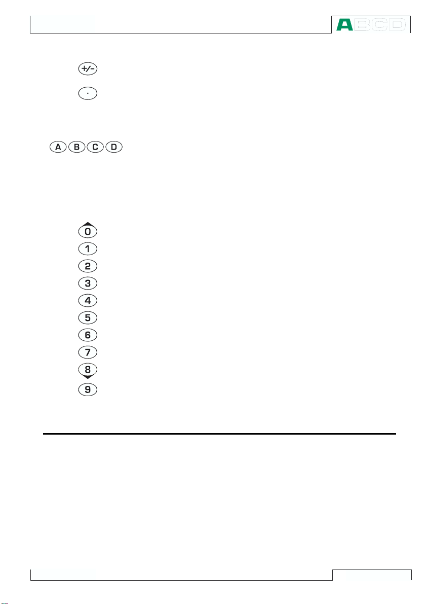
Pressing the +/- key toggles the sign of the entered numeric value.
Note. The +/- key is applicable only in numeric fields.
The Decimal key adds the decimal point to the numeric value that
is currently edited.
The Function Keys
The Function Keys are located below the display. The meaning of
each Function Key varies depending on the situation. The lower
part of the display indicates what the Function Key stands for at the
moment.
The Numeric Keys
The Numeric keys are not only used when entering numbers:
· Keys 1 to 7 are used as menu selector keys.
· Keys 0 and 8 may be used when browsing through options in
drop down lists and selection lists.
· Key 9 can be used when accepting a selection or when finish-
ing a data entry. The functionality of the 9 key is almost similar
to the Enter key, except for one situation: When entering numbers, the 9 key produces the number 9. To finish entering a
number, you will have to use the Enter key or use the
Function Key when available.
D/OK
Memory
MC3 has a dynamic memory allocation system. This means that
there is not a specific area of memory reserved for, e.g. instrument
data. All free memory may be used for anything that requires more
memory. Thus there is no exact limit for the number of instruments
that MC3 can maintain in its memory. It all depends on how much
memory is allocated by other data.
9
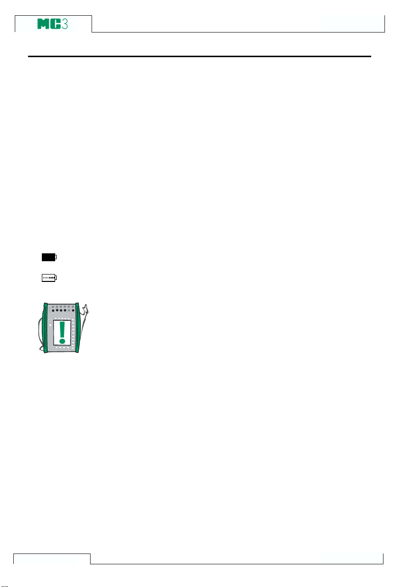
Batteries
Full batteries:
Empty batteries:
General
MC3 uses rechargeable batteries. The charger for rechargeable
batteries operates in the following environments:
- Voltage: 100240 VAC,
- Frequency: 50/60 Hz
The charging electronics is in the Battery Pack. Therefore the batteries may be charged although the Battery Pack is disconnected
from MC3s Base Unit. If you have two sets of rechargeable batteries you may charge the disconnected Battery Pack while at the
same time use MC3 with the connected Battery Pack.
The maximum operating time without recharging varies depending
on the usage and brightness setting of the display light. Also the
generated output current and the usage of the 24V transmitter supply affect the maximum operating time. Even with constant maximum load, the standard rechargeable batteries should last for 6
hours. A good average operating time is 10 hours.
The upper left corner of MC3s display shows a picture of a battery.
The whiter the picture is, the more acute is the need for recharging.
Notes.
MC3s memory and the internal clock/calendar uses a small amount
of power although the calibrator is switched off. Remember to check
the capacity of the batteries from time to time although MC3 is not
in use.
Do not leave MC3 without a Battery Pack for a long time. MC3 may
loose its settings if it is left without a support voltage for an extended period.
10
MC3 Hardware
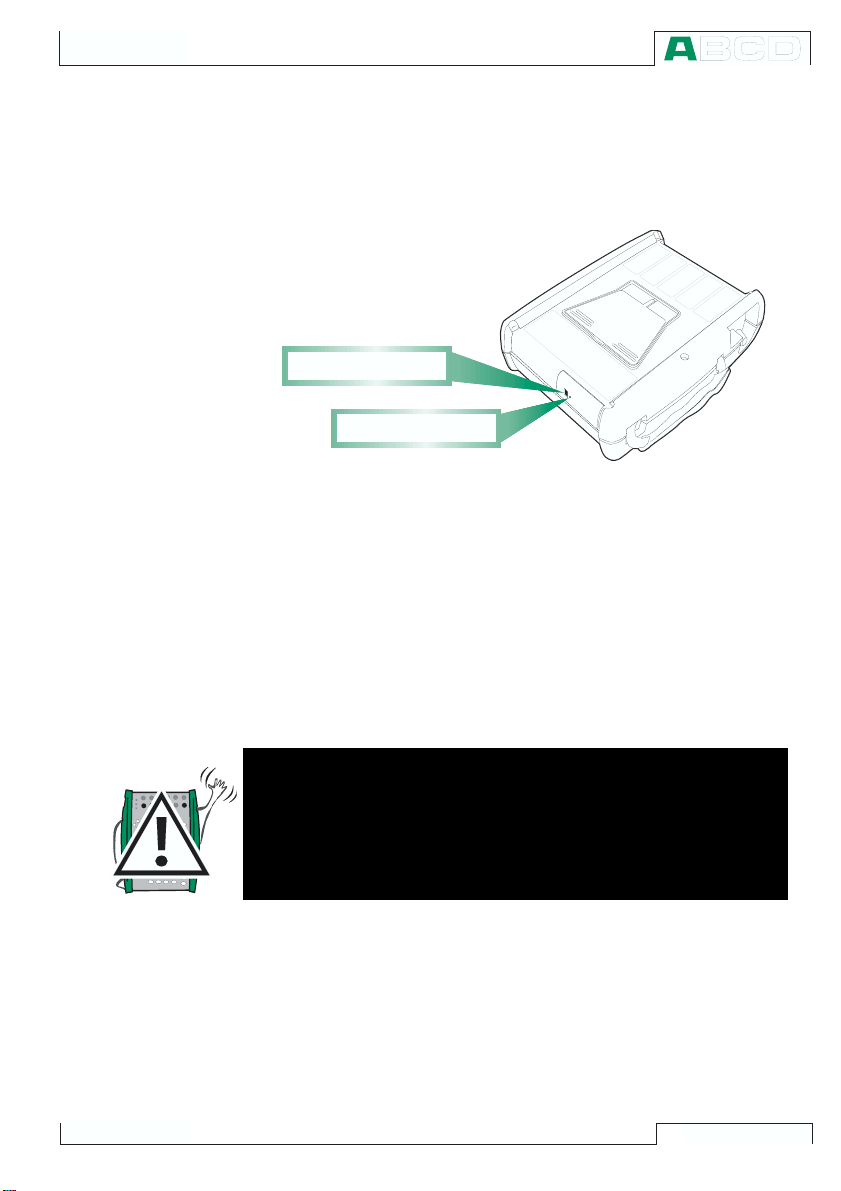
About the Charger and the Charging Procedure
The charger is connected to the charger connector at the bottom of
MC3. The charging electronics informs you of the phases of the
charging procedure with the help of the charge status light.
C h a r g e r c o n n e c t o r
C h a r g e s t a t u s l i g h t
When connecting the charger, the charging electronics first checks
the charge level of the batteries. At this stage, no light is visible in
the charge status light.
When the charge status light is red, a recharging is either starting
(blinking red light) or in progress (constant red light). MC3 may be
used during the recharging phase. Empty batteries are fully charged
in approx. 2½ hours.
When the charge status light is green, the batteries are charged. At
this stage the charging electronics provide a support voltage that
prevents the batteries from discharging
Warnings!
USE ONLY THE CHARGER PROVIDED WITH THE CALIBRATOR.
The charger accepts input voltages from 100 to 240VAC.
The charger should only be used indoors and the temperature
should not exceed 40 °C (104 °F).
11
General
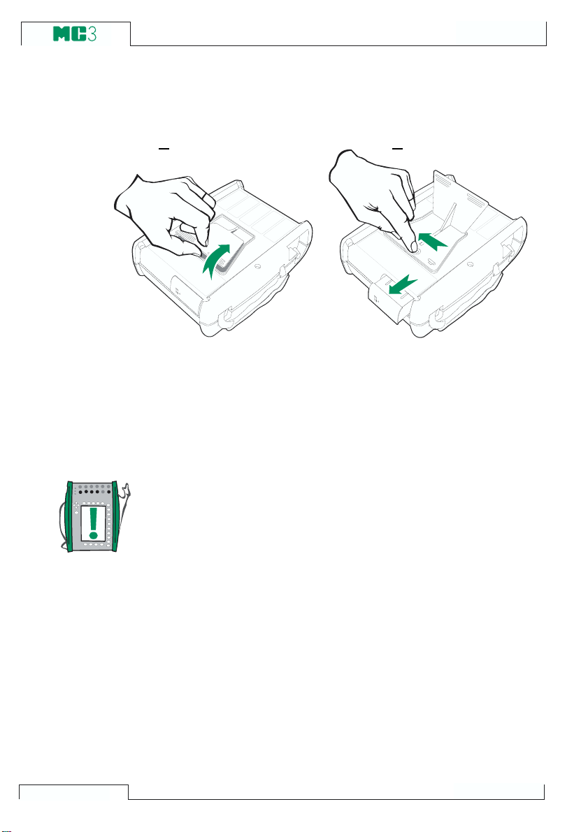
Removing/Replacing the Battery Pack
To remove or replace the Battery Pack, perform the following procedure:
1. 2.
1. Turn MC3 upside down (the display facing the table top) and
lift the support.
2. Pull the lever that is hidden under the support. The Battery
Pack pops out allowing you to pull it out.
To replace the Battery Pack, simply slide it on its place. When you
hear a click, the Battery Pack is secured in its place.
12
Note.
Although the Base Unit is IP65 protected, the Battery Pack is not.
The Battery Pack has holes in order to vent generated gas and
heat. Avoid exposing the Battery Pack to liquids.

MC3 Hardware
Support for Table Top Use
The support gives you a good viewing angle when MC3 is placed
on a table top. Lift the support at the back of MC3 and place MC3
on the table top as shown in the picture.
The Wrist Strap and the Neck Support Strap
MC3 has a wrist strap to enable ease of use
when MC3 is held in one hand. The neck support strap helps you during field calibration:
Position MC3 in an angle that allows reading
the display when working. Alternatively: Hang
MC3 from, e.g. a valve shaft so that the display is on the same level as your eyes. Then
your hands are free for working with the connections etc.
The Optional Carrying Case
MC3s soft carrying case is practical when moving from a location
to another. The carrying case can also be used for transporting
utilities, like:
· Test hoses, test leads and clips
· A pressure pump
· Temperature sensors
· Charger and its cable
· User Guide (this book)
The carrying case is suited for use in normal industrial environment.
13

General
MC3 Firmware
General Description
The following picture shortly describes the functions of the firmware. All main functions are marked with a black border. Each main
function has several tasks which are displayed as shaded boxes
without a black border.
M E N U S T R U C T U R E
M E N U S T R U C T U R E
I n s t r u m e n t A d j u s t m e n t
I n s t r u m e n t C a l i b r a t i o n
V i e w i n g t h e R e s u l t s
I n s t r u m e n t D a t a b a s e M a i n t e n a n c e
P R O C E D U R E
P R O C E D U R E
C A L I B R A T I O N
M O D E
S T A R T U P
S T A R T U P
B A S I C
M O D E
S t e p p i n g a n d R a m p i n g
M e a s u r e m e n t / G e n e r a t i o n / S i m u l a t i o n
M A I N T E -
M A I N T E -
N A N C E
N A N C E
C o n f i g u r i n g t h e C a l i b r a t o r
S e t t i n g T i m e a n d D a t e
A d j u s t i n g t h e C a l i b r a t o r
Startup Procedure
14
The following chapters briefly describe each main function.
Every time MC3 is started the Startup Procedure checks the functionality of the device by performing a self test.
If the self-test is passed successfully, some basic calibrator data is
displayed.
After that MC3 automatically proceeds to Basic Mode. A more comprehensive description of the Startup Procedure is in the beginning
of Part B of this manual.

Basic Mode
Maintenance
Calibration Mode
MC3 Firmware
In Basic Mode you can measure and generate/simulate signals.
There are two separately configurable windows available. Basic
Mode is often used for testing connections before starting the actual calibration procedure of an instrument.
Stepping and Ramping tools enable generating/simulating signals
that vary with time.
All main functions of Basic Mode are described in part B of this
manual.
This main function handles calibrator configuration settings.
Additionally there is the possibility to recalibrate MC3 (requires a
password).
Maintenance level subjects are handled in Part C of this Manual.
MC3s main duty is calibrating instruments. Therefore very special
attention was directed on this matter when creating the calibrator.
MC3 may be used as a stand-alone calibrator i.e. all instrument
data and calibration data is saved in MC3s own memory. Optionally MC3 also communicates with calibration software.
MC3 supports the use of instruction texts. They help the technician
to perform the calibration as fluently as possible. You may enter
three kinds of instruction texts: Starting Guide, Adjusting Guide
and Finishing Guide. Additionally, calibration notes can be entered
after the calibration procedure.
More calibration related information is available in Part D of this
manual.
Calibration Results
The graphical representation as well as numeric data of the calibration results may be viewed in MC3. Transferring the results to QCAL
calibration software makes it possible to view the results in PC environment.
More information concerning calibration results is presented in Part
D of this manual.
®
15

The User Interface
The main elements of the User window can be seen in the following
picture:
All possible elements are not included in the previous picture, but
the important ones are discussed in the following chapters.
The Status Bar
The Status Bar at the top
of the display is visible all
the time. It is divided into
three main sections.
The first (leftmost) section displays the charge level of the battery.
The second section displays the time and date.
The third section (rightmost) section displays additional information
in the form of symbols, like:
Note that the third section is empty for most of the time. The symbols are visible only when needed.
General
M e n u
A l a r m <
Q u a n t i t y
[ P r e s s u r e ]
( g a u g e )
F u n c t / P o r t
m b a r
[ P 1 : P R 2 C ]
b a r
k P a
U n i t
P a
[ b a r ]
b a r
p s i
m m H
O
2
m m H g
P r e s s u r e
T y p e
[ g a u g e ]
Z e r o
P r e s s u r e
M o d u l e
C l o s eW i n d o w 1 W i n d o w 2
O t h e r s
M E N UM o d e
S e c t i o n s :
1 2 3
T i m e & D a t e
A d d i t i o n a l
i n f o r m a t i o n
P o p - u p l i s t
P r e s e n t
s e l e c t i o n
B a t t e r y ' s c h a r g e l e v e l
M e a s u r e m e n t r e a d i n g
D i s p l a y a r e a d i v i d e d
i n t o W i n d o w 1 a n d 2
S t a t u s B a r
2 5 . 0 4 . 2 0 0 1 1 1 : 5 9
P r e s s u r e
1
P 1 : P R 2 C / - 1 . 0 0 0 0 0 0 . . . 2 b a r
0 . 4 5 2 1
2 C u r r e n t
E : C u r r e n t M e a s u r e m e n t
0 . 1 1 2
S e t u p S e t u p
F u n c t i o n k e y b a r
E x a m p l e o f S t a t u s
B a r a p p e a r a n c e
· An hourglass when MC3 is working on something that takes
time.
· A question mark when an error occurred.
16

The Function Key Bar
C l o s e
M E N UM o d e
O t h e r s
0 . 7 0 8 3 4
m b a r
( g a u g e )
A l a r m <
P 1 : P R 2 C / - 1 . 0 0 0 0 0 0 . . . 2 b a r
0 . 5
0 . 4 3 7 4
2 C u r r e n t
b a r
P r e s s u r e
E : C u r r e n t M e a s u r e m e n t
Q u a n t i t y
[ P r e s s u r e ]
[ P 1 : P R 2 C ]
U n i t
[ b a r ]
F u n c t / P o r t
2 9 . 0 1 . 2 0 0 1 1 3 : 2 0
1
P r e s s u r e
T y p e
[ g a u g e ]
Z e r o
P r e s s u r e
M o d u l e
W i n d o w 1 W i n d o w 2
S e t u p S e t u p
Menus
MC3 Firmware
The Function Key Bar at the bottom of the display is visible all the
time. The meaning of the Function Keys varies depending on the
situation. A grayed Function key text means that the function is disabled at the moment.
C l o s eW i n d o w 1 W i n d o w 2
S e t u p S e t u p
O t h e r s
M o d e
M E N U
The Function Key for opening the
menu is always D/Menu. The same
key is used when closing the menu.
If a menu is not needed for the current subject, the fourth Function Key
is used for other needs.
A menu option is selected with the
numeric keys to . Selecting a
menu option results in one of the following events:
1. An immediate action follows and
the menu closes automatically,
e.g. when selecting the
Pressure Module option in the
Zero
picture above.
2. A pop-up list opens for selecting one of the available options.
The current selection is displayed inside brackets in the menu.
Use the and keys or the and keys to scroll the popup list. To select an option in the pop-up list, use either the
key or the D/Select Function key. To close the pop-up menu
without selecting anything, press the key or the A/Cancel
Function Key.
3. A new window opens for, e.g. viewing additional information or
for configuring the selected task.
Sometimes a Function Key can open another menu. In the previous picture, the Window 1 setup menu is opened. In this case Function Key
used for opening other menus.
B/Window2Setup and Function Key C/Others can be
17

The Display Area
General
The layout of the display area varies according to the needs of the
active tasks/settings. The following
pictures give an overview of typical
elements seen in different display
area layouts.
Basic Measurement/Generation:
2 9 . 0 1 . 2 0 0 1 1 3 : 2 3
1
F r e q u e n c y
E T : F r e q u e n c y G e n .
1 . 0 0 0 0 0
A m p l i t u d e [ V p p ]
p o s . s q u a r e
k H z
5 . 0 0
The display area is divided into two
windows with informative texts and
numeric measurement/generation
values.
2
C u r r e n t
E : C u r r e n t M e a s u r e m e n t
1 1 . 9 8 3 7
m A
A border surrounding a numeric
value indicates that the field is
editable. It is, e.g. a generation field
for entering generation values.
If several editable fields are visible,
choose the active field with the cursor keys or the
B/Field Function
Key.
Calibration:
The display area is divided into
three windows during a calibration.
The first window displays data related to the instruments input signal. The second corresponding
data related to the output signal.
The third window displays the error graph. The error graph is also
seen among calibration result data.
Configuration Window:
There are plenty of configuration
windows in MC3. The picture beside is the configuration window for
Ramping settings.
The common thing for all configuration windows is that they reserve
the whole display area for the con-
C a l i b r a t i o n
I n p u t
O u t p u t
E r r o r
0 . 4 0
+
0
-
Q u a n t i t y
P o r t
W a i t i n 0 %
R i s e T i m e
W a i t i n 1 0 0 %
F a l l T i m e
R e p e a t s
0 = c o n t i n u o u s
F i e l d
M o d e
2 9 . 0 1 . 2 0 0 1 1 2 : 1 4
R T D T e m p e r a t u r e [ E T : S i m u l . ]
5 0 . 0 0
C u r r e n t [ E : M e a s . ]
1 1 . 9 9 2 5
0 % 5 0 % 1 0 0 %
F o r c e
P a u s e
A c c e p t
2 9 . 0 1 . 2 0 0 1 1 3 : 2 6
R A M P I N G
C u r r e n t
E : I ( g e n )
2
1
2
2
1
P t 1 0 0 =3 8 5
° C ( I T S 9 0 )
m A
- 0 . 0 5 % o f s p a n
s
s
s
s
M E N U
figuration fields.
Use the cursor keys to move be-
tween fields.
R a n g e 0 %
C a n c e l S t a r t
1 0 0 %
8 . 0 0 0 0
1 6 . 0 0 0 0
m A
18

2 5 . 0 4 . 2 0 0 1 1 2 : 1 3
W a i t
S e r i a l n u m b e r
E m o d u l e v e r s i o n
C a l i b r a t i o n d u e d a t e
M a i n v e r s i o n
E T m o d u l e v e r s i o n
2 3 5 1 2 3 6 5
1 . 3 0
1 0 . 1 2 . 2 0 0 1
1 . 0 0
1 . 5 0
M C 3
S e r i a l N u m b e r : 3 0 3 2 8 2 5 2
M a i n V e r s i o n : 1 . 1 0
E m o d u l e v e r s i o n : 1 . 3 0
E T m o d u l e v e r s i o n : 1 . 5 0
M o d u l e N a m e
§
S e r i a l N u m b e r § D a t e
R J
§
7 3 3 4 4 § 1 5 . 1 2 . 2 0 0 0
E T
§
5 2 2 2 5 § 1 5 . 1 2 . 2 0 0 0
E
§
3 1 2 0 2 § 1 5 . 1 2 . 2 0 0 0
P R B
§
1 5 7 6 3 § 1 5 . 1 2 . 2 0 0 0
P R 2 0 C
§
1 5 4 4 2 § 1 5 . 1 2 . 2 0 0 0
C l o s e
M F
MC3 Firmware
Tables:
Tables are used, e.g. when viewing calibration results in numeric
format. Tables reserve the whole
display area.
The tables are often larger than the
display. In that case there are small
arrows added to the table borders.
They indicate that more information
may be seen by using the arrow
keys.
and keys scroll the list one
The
line at a time. The
and keys
scroll the list one page at a time (if
applicable).
Info window:
Pressing the Info key
opens up
the info window. It can be called at
any time. The info window displays
information on the available sections and the firmware version numbers.
Display Area Elements that are Used for Editing Data
There are four different fields/elements that are used for editing data in the display area. Use the
Field Function Key to move between editable fields in Basic Mode.
In configuration windows, use the cursor keys.
2 9 . 0 1 . 2 0 0 1 1 3 : 2 7
1 2 . 0 2 . 2 0 0 0 1 0 : 2 9 - A s F o u n d - P a s s e d
I n p u t
- 0 . 0 0 0 0 2
0 . 9 9 9 9 6
1 . 9 9 9 9 8
3 . 0 0 0 0
4 . 0 0 0 0
5 . 0 0 0 0
6 . 0 0 0 0
7 . 0 0 0 0
8 . 0 0 0 0
9 . 0 0 0 0
9 . 9 9 9 9
9 . 0 0 0 0
8 . 0 0 0 0
B a c k
O u t p u t
N e x t
P a g e
[ V ]
- 0 . 0 0 0 0 5
0 . 9 9 9 9 6
2 . 0 0 0 0
3 . 0 0 0 1
4 . 0 0 0 1
5 . 0 0 0 2
6 . 0 0 0 1
7 . 0 0 0 1
8 . 0 0 0 1
9 . 0 0 0 2
1 0 . 0 0 0 1
9 . 0 0 0 2
8 . 0 0 0 2
[ V ]
1 2
E r r o r
0 . 0 0 3
0 . 0 0 0
0 . 0 0 2
0 . 0 0 1
0 . 0 0 1
0 . 0 0 2
0 . 0 0 1
0 . 0 0 1
0 . 0 0 1
0 . 0 0 2
0 . 0 0 2
0 . 0 0 2
0 . 0 0 2
[ % ]
M E N U
B/
Numeric Fields
There are two ways to start editing a
numeric field:
1. Press a numeric key,
or
key. Then the entered value re-
R a n g e 0 %
R a n g e 0 %
1 0 0 %
1 0 0 %
4 . 0 0 0 0
1 6 . 0 0 0 0
4 . 0 0 0 0
2 0 _
m A
m A
places the old value.
2. Press the key or the C/Edit Function Key available in some
configuration windows. Then you can edit the old value. New
digits appear at the end of the old value.
Accept the new value by pressing the
key or the D/OK Function
Key. To discard the edited value, use the A/Cancel Function Key.
19
General
Notes.
You cannot add more digits if the length of the number is at its
maximum limit. Use the C/çDelete Function Key to remove unwanted digits first and then enter the new digits.
The dual function of the keys: , and is not available in a
numeric field. The keys only represent numbers.
Text fields
P o s i t i o n I D
P T 1 0 6 . 1
Press any of the numeric keys or
C/Edit Function Key available
the
in some configuration windows to
start editing a text field. Then the
2 9 . 0 1 . 2 0 0 1 1 3 : 1 2
P T 1 0 6 . 1
menu with the available characters
opens for selecting. Use the numeric keys (1 to 7) to select the
character. Use the cursor keys to
move the cursor in the text field.
Select the character with the
key. Use the C/çDelete Function
Key to remove unwanted characters. If the character you want to use
is not seen in the list of available
characters, try the
or the key
D e v i c e I D
D e v i c e N a m e
E r r o r C a l c . M e t h o d
R e j e c t i f
A d j u s t i f
D o n o t A d j u s t i f
A d j u s t t o
C a n c e l D e l e t e A c c e p t
% o f s p a n
0 . 5 0
>
0 . 3 0
>
0 . 1 0
<
0 . 1 0
<
to see more alternatives.
Accept the new text with the
D/Accept Function Key. To discard
(cancel) the edited text, use the A/Cancel Function Key.
A B C
D E F
G H I
J K L
M N O
P Q R
S T U
V W X
Y Z Å
Ä Ö O
Æ Ë Ï
Ü Â Ê
Î Ô
Û Ç ß
20
MC3 Firmware
Drop Down Lists
I n p u t M e t h o d
M e a s u r e d
Drop Down Lists are used when
there is a limited amount of preset
values. You have to select one of the
available options. The list of avail-
I n p u t M e t h o d
M e a s u r e d
M e a s u r e d
K e y e d
C o n t r o l l e d
able options is displayed either below or above the Drop Down List
field.
A Drop Down List opens when you press the
key or any of the
numeric keys or the C/Edit Function Key available in some configuration windows. Small arrows in the upper right and/or lower right
corner indicates that the list is longer than the visible part.
Selection Lists
Selection lists are used when you
have to choose one of several options. Selection lists are often large,
thus almost reserving the whole
window. Selection lists can be
longer than the visible part. When
the cursor (the row with the inverted
text) is on the bottom and you press
key, the list scrolls and dis-
the
plays more options. The and
keys scroll the list one line at a time.
The and keys to scroll the list
one page at a time (if applicable).
Select one of the options with the
C/Select Function Key or either the
2 9 . 0 1 . 2 0 0 1 1 3 : 1 5
P O S I T I O N / D E V I C E I D
1 0 1 - X L - 0 0 1 . 1
1 1 2 - T T - 0 0 3 . 1
1 1 2 - T T - 0 0 7 . 1
E S w
P T 1 0 6 . 1
P T 1 1 2 . 1 2
P T 1 1 2 . 1 5 - 1
P T 1 1 2 . 1 5 - 2
P T 1 1 2 . 1 6
T I
V V
D e v i c e I D
T T 1 1 2 . 0 9
P o s i t i o n N a m e
P r o d u c t t e m p e r a t u r e
C a l i b r a t e d
2 2 . 0 2 . 2 0 0 1
B a s i c
M o d e
S e l e c t
M E N U
key or the key.
MC3s Firmware Option
The standard firmware shipped with MC3 is capable of performing
all normal measurement, generation/simulation and calibration
tasks.
The following firmware option is available:
· Communication with QCAL® software. The option also includes
a cable for communication between MC3 and the QCAL® software.
21

General
Safety
MC3s case is water/dust proof (IP65). The battery pack does however have holes to enable proper ventilation and heat transfer. So
be careful when working in wet conditions.
The materials of MC3s case withstand normal industrial conditions.
MC3 endures shocks with the help of the built in impact protectors
Certifications and Compliances (EC Declaration of Conformity)
MC3 conforms to the EMC directive 89/336/EEC as attested by
conformity with the following harmonized standards:
EN 50081-1 Emission,
EN 50081-1 Immunity,
EN 61000-3-2 Harmonic currents,
EN 61000-3-3 Voltage fluctuations,
and the low voltage directive 73/23/EEC as attested by conformity
with the following harmonized standard:
EN 60950 Low Voltage.
22

Safety Precautions and Warnings
MC3 calibrator is a precision calibration tool that should be used by
skilled people. Working with MC3 involves the usage of pressure,
temperature and/or electrical instruments. Be sure to know how to
work with these instruments and how to safely connect/disconnect
pressure hoses as well as electrical test leads clips, etc.
Use MC3 only if you are certain of that it can be used safely. Safe
use of MC3 is no longer possible if one or more of the following
cases are true:
· When the case of MC3 is evidently damaged
· When MC3 is not functioning as expected
· After prolonged storage in unfavorable conditions
· After serious damage during transport
Sometimes it is necessary to use a portable radio transceiver while
working with the calibrator. To prevent calibration errors caused by
the radio frequency interference, keep the radio far (at least 1 meter)
from the calibrator and the circuit under calibration while sending.
General Warnings
Use only cables provided by Beamex when connecting MC3 to
a PC.
Use the MC3 battery charger in a non-hazardous indoor location only and only with Beamex calibrators.
MC3 uses rechargeable batteries. They are considered as hazardous waste. Dispose used batteries properly according to
local regulations.
Avoid short circuiting the batteries. The short circuit current
may cause burns to you, damage to the device or even fire.
Notice, that also new replacement batteries are shipped in
charged state.
Rechargeable batteries may vent small amounts of gas during
recharge. The vented gas mixture may be highly explosive, but
normally it diffuses rapidly into the atmosphere. To avoid danger, use only the original charger and never recharge in a gastight container.
The charger should only be used indoors and the temperature
should not exceed 40 °C (104 °F).
Safety
23

General
Warnings Concerning the use of E and ET Sections
The measurement and generation terminals of MC3 are protected against over voltage and over current as far as it has
been possible without affecting the accuracy. The circuits are
designed so, that you can connect a voltage source 50VDC/2A
between any terminals without damaging the device. However,
long exposure to this kind of stress may affect the accuracy.
Although there is a galvanic isolation between MC3s ET and E
sections, it is for functional purposes only. The max. 50 V restriction applies between these sections too.
Maximum output voltage from MC3s terminals is below 30V. If
you, however, connect together voltages from the ET and E
sections or if you connect external voltages to MC3, the resulting voltage may be high enough to be hazardous.
General Warnings Concerning Pressure Measurement
The accessory polyurethane hose supplied with an MC3 with a
pressure input is rated to the maximum pressure of 20bar at
21°C (290psi at 70°F). Applying higher pressure can be hazardous.
To avoid damaging the calibrator, use hand tightening only
when connecting the pressure measurement hoses (max.
torque 5 Nm). If the use of tools is required to secure the connection (typically pressure inputs with a pressure range of 20
bar or more), apply the counterforce with a spanner on the connector bodys hexagonal part.
Always depressurize the system before opening or connecting
any pressure fittings or connectors. Use proper valves for venting the system. Ensure that all connections are made correctly
and that the hose and the connectors are intact.
Always use the pressure media stated in the inputs sticker.
Using unsuitable pressure media may destroy the pressure
sensor. The pressure inputs sticker is located at the rear of
MC3.
Never exceed the maximum pressure of a pressure input. The
pressure inputs maximum pressure is stated on the inputs
sticker.
Never plug a hose with your hands or put the hands in front of
a gas spray coming from a leakage. A gas bubble in the blood
circulation can cause death.
24

Warnings Concerning High Pressure
High pressure is always dangerous. Only personnel with good
experience and knowledge of high pressure liquid, air and nitrogen operations are allowed to work with the input. Read
carefully all these instructions and local safety instructions for
high pressure operations before starting the use.
When using gas, the system must not contain any liquid, especially if you do not know how they may react under pressure.
Use of clean air or nitrogen is recommended as gaseous pressure media. Liquid pressure media should be preferred when
using inputs with a pressure range of 60 bar (30000 psi) or
more.
If you use nitrogen, minimize the leak to the atmosphere and
take care of sufficient ventilation. Close the valve of the nitrogen cylinder, when the system is not in use. Increase in the
percentage of nitrogen in the ambient air may cause unconsciousness and death without warning. Read carefully the
safety instructions for nitrogen and make sure that the other
people in the same space are aware of the danger.
Use of liquid pressure medium is recommended with pressure
measurement inputs at higher pressure range. Use water or
suitable hydraulic oil. Check that the used liquid is not aggressive against the materials used in the transducer or tubing.
When using liquid, minimize the amount of air in the system.
So you can minimize the amount of spilled liquid in case of
leakage.
Do not use the same tubing with different liquids or gases.
Check what the local regulations say about construction and
use of pressurized vessels. The regulations normally control
construction and use of systems where the product of the pressure and volume exceeds a certain limit. The volume of this
system depends on the instrument connected to it.
High pressure gas is dangerous because it can break the container and the flying splinters may cause injury. Also small leaks
of gas may be dangerous because the high velocity of the leaking gas jet enables penetration through skin. If a gas bubble
gets into the blood circulation, it can cause death. The leak jet
is particularly penetrative, if some liquid is coming with the
gas.
Safety
25

General
Service
Only qualified service personnel may perform higher level maintenance for MC3. Never open the case unless have explicit in-
structions from Beamex or a local representative.
There are, however a few things that anyone using MC3 may do.
Recalibrating MC3
Only laboratories approved by Beamex may recalibrate MC3. Contact Beamex or your local representative for information concerning the recalibration of MC3. Contact information is on the first pages
of this User Guide.
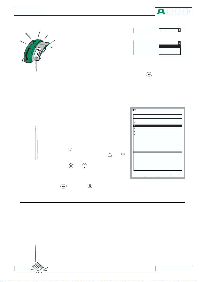
Cleaning the Contacts of the Internal Reference Junction
The contacts of the Internal Reference Junction may need cleaning
from time to time. The time period varies depending on the environment MC3 is used in.
Carefully open the cover of the Internal Reference Junction by using a screwdriver as a wrench. Now you can see the contacts. Remove all impurities and press back the cover. The cover is secured
when you hear a click.
The Battery Charger
26
The charger is not intended to be serviced. When unusable it can
be thrown away according to local waste disposal regulations.

Startup and Basic
Operation
Things discussed in Part B:
· What happens during the
· Measuring signals.
· Generating/simulating signals.
· Step and Ramp functions.
startup procedure.

Startup and Basic Operation
Starting MC3
Startup Procedure
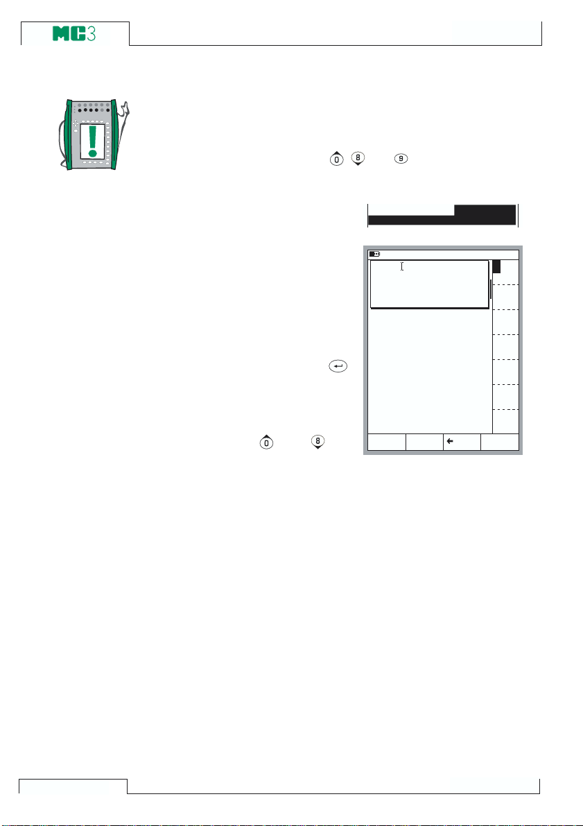
When MC3 is started, a startup picture appears. After a self test,
some basic information of the calibrator at hand appears in the lower
part of the screen. The graphic in the upper part includes information on the model of the MC3 at hand (MC3MF, MC4PE or MC3TE). If
you want to view the calibrator information for a longer period, press
1 8 . 0 6 . 2 0 0 1 1 2 : 2 9
M F
28
S e r i a l n u m b e r
M a i n v e r s i o n
C a l i b r a t i o n d u e d a t e
3 0 3 2 8 2 5 2
1 . 1 0
1 0 . 1 2 . 2 0 0 1
W a i t
the D/Wait function key. Then the calibrator information is visible
until you press the D/Continue function key.
The calibration due date that is listed in the startup window is the
earliest calibration due date for all sections.

Basic Mode, Defined
Every time MC3 is switched on, the startup procedure ends in Basic
Mode.
All non-calibration related measurements and generations are performed in the Basic Mode. Briefly: in Basic Mode MC3 works like a
high quality multimeter. When returning from MC3s higher level
operations (calibration, viewing of calibration results, calibrator and
user configurations), you always return to the Basic Mode.
Starting MC3
B a s i c M o d e :
M e a s u r e m e n t
G e n e r a t i o n . . .
W h e r e
s h o u l d I g o
t o d a y . . .
In Basic Mode, the two available measurement/generation/simulation windows have default settings based either on factory settings
or settings defined when MC3 was previously used.
The first time the D/Menu key is pressed, the Window1Setup
menu is available. Other possible menus can be selected from the
function keys: B/Window2Setup and C/Others. The latter function
key opens a menu with a possibility to change the general setiings
of MC3.
29

Startup and Basic Operation
Example of a Basic Mode screen
with pressure measurement configured in Window 1 and current measurement configured in Window 2:
What can be done in Basic Mode
· Measure signals (*
· Generate signals (*
· Simulate signals (**
· Perform a Limit Switch Test
· Use the ramping function
· Use the stepping function
*) Available options depend on the installed sections.
**) Simulation only available in models MC3
2 9 . 0 1 . 2 0 0 1 1 3 : 2 5
1
P r e s s u r e
P 1 : P R 2 0 C / - 1 . 0 0 0 0 . . . 2 0 . 6 8 4 0 b a r g
2 . 6 4 7 5
2
C u r r e n t
E : C u r r e n t M e a s u r e m e n t
1 2 . 4 7 3 1
C a l i b r a t i o n
M o d e
MF
and MC3TE.
g a u g e
b a r
m A
M E N U
30
Next
Measuring on page 31
Generating/Simulating on page 45
Special Generations on page 56.

Measuring
Measuring
All measurements in Basic Mode require that you first select the
Window to be used (Commands: Start with D/Menu and continue
either with A/Window1Setup or B/Window2Setup). Each measurement has its own unique 1/Quantity and 2/Function/Port set-
tings in their windows menu. The other window menu settings, e.g.
measuring unit, refine the measurement characteristics.
Because all measurements are not available in all MC3 models,
the presentation of each measurement include a description of MC3
models supporting this measurement. The required section for the
measurement is also mentioned. If the section is not included in
your MC3, the
1/Quantity and 2/Function/Port settings needed
for the measurement are not available as choices in the pop-up
lists.
Each measurement also has at least one picture with a circle around
some of MC3s terminals, like the one below.
V , 1,
V , ,
O U T P U TM E A S U R E & S I M U L A T E M E A S U R E
E T E
2 - w x m t r
+ 2 4 V
1
m e a s / s in k
1/Quantity and
T / C IN T . R J
4 - w m e a s
R , R T D
3 & 4 - w m e a s
T / C O R E X T
W I R E S O N L Y
T / C , L o w V
The circle indicates active terminals for each
2/Function/Port setting in the window menu.
If the picture has more than two terminals circled, then the lighter
part is somehow optional. In the following picture, the third and fourth
RTD measurement terminals are optional.
V , 1,
V , ,
O U T P U TM E A S U R E & S IM U L A T E M E A S U R E
E T E
2 - w x m t r
+ 2 4 V
1
m e a s / s in k
T / C IN T . R J
T / C O R E X T
W I R E S O N L Y
T / C , L o w V
4 - w m e a s
R , R T D
3 & 4 - w m e a s
Warning!
Do not apply voltage higher than 50V (max 2A) between any
terminals.
31

Startup and Basic Operation
Pressure Measurement
Pressure measurement is possible with models MC3MF and MC4PE.
See chapter Things to Consider when Measuring Pressure on page 66 for more infor-
mation on pressure measurement and pressure inputs.
Required settings Options/description
Quantity Pressure
Port P1:PRxxxx (or P3:PRB, if applicable)
Pressure Type g gauge pressure or
abs absolute pressure.
The available pressure types may be restricted because of the selected pressure
port/pressure input. For more information
concerning pressure types, see chapter
Pressure Type on page 66 .
The following picture displays the active
input, when P1:PRxxxx is selected. If the
barometric option is available, it measures
the barometric pressure through an opening at the back side of MC3.
T / C IN T . R J
T /C O R EX T
W IR E S O NL Y
T / C , L o w V
4 -w m e as
R , R T D
3 & 4- w m e a s
V , 1,
V , ,
O U TP U TM E A SU R E & S IM U L AT E M E A S U RE
E T E
2 -w x m t r
+ 2 4 V
1
m e as / s in k
Zeroing the Gauge Pressure
If the pressure input does not display zero gauge pressure when
the applied pressure is zero, it has to be zeroed.
Open the appropriate window setup menu (
Setup or B/Window2Setup) and select menu option 7/Zero Pres-
sure Module.
NOTE!
Zeroing a pressure input is especially important when the op-
erating position of MC3 is changed or the location of MC3 is
changed in the vertical direction. Both of the above mentioned
factors affect notably on the pressure measurement input.
Measuring pressure below 100 mbar (approx. 40 iwc) should
be done with a firmly mounted MC3 (e.g. placed on a table top).
Next
Calibration, see Part D.
32
D/Menu, A/Window1
Measuring
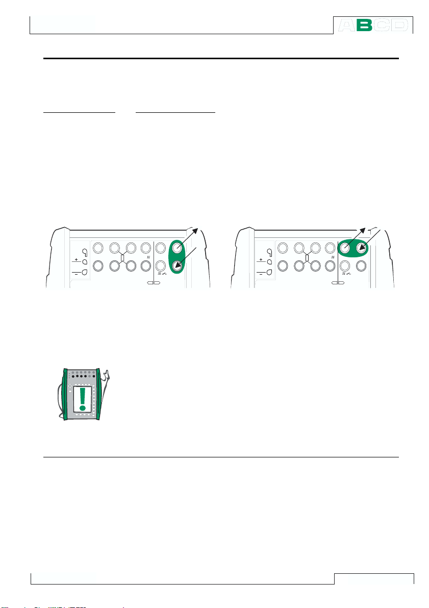
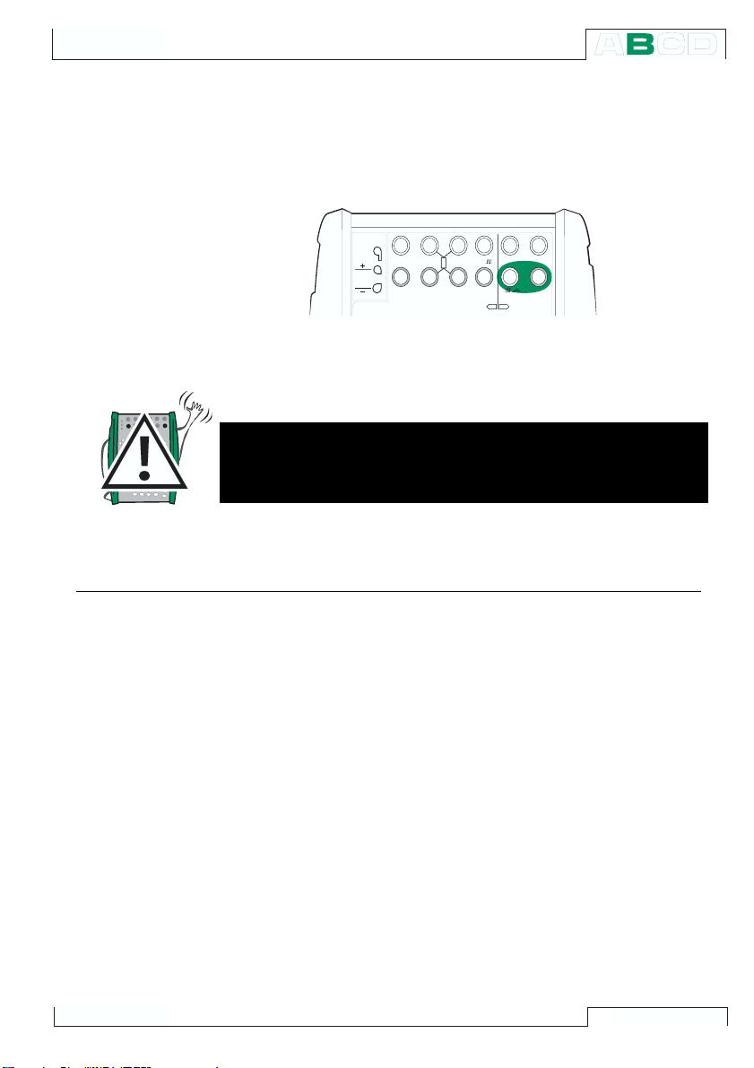
Current Measurement
Current measurement is possible with all MC3 models. The current measurement terminals are located in the E section.
Required settings Options/description
Quantity Current
Funct/Port E:I(meas)
External supply
When the measuring circuit includes an
external power supply, use the terminals
shown in the picture below.
V , 1,
V , ,
O U T P U TM E A S U R E & S I M U L A T E M E A S U R E
E T E
2 - w x m t r
+ 2 4 V
1
m e a s / s in k
Next
T / C IN T . R J
T / C O R E X T
W I R E S O N L Y
T / C , L o w V
4 - w m e a s
R , R T D
3 & 4 - w m e a s
Based on the terminals in use, MC3 automatically acts as either a
pure current measuring unit or as a current measuring unit while at
the same time supplying the measuring circuit.
Notes.
Check the polarity of your connections. The arrows in the previous
pictures describe the correct flow of current.
Information concerning current measurement parallel to a test di-
ode can be found in part C, chapter Current Measurement Paral-
lel to a Test Diode, Connections on page 73.
Current Generation on page 47
Calibration, see Part D.
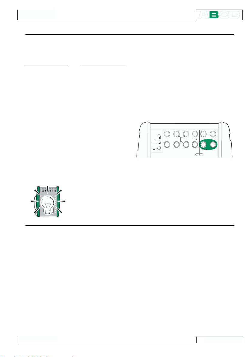
Internal Supply
When you want to use MC3s 24 V terminal to supply the measuring circuit, use the
terminals shown in the picture below.
V , 1,
O U T P U TM E A S U R E & S I M U L A T E M E A S U R E
E T E
2 - w x m t r
+ 2 4 V
1
m e a s / s in k
V , ,
T / C IN T . R J
T / C O R E X T
W I R E S O N L Y
T / C , L o w V
4 - w m e a s
R , R T D
3 & 4 - w m e a s
33

Startup and Basic Operation
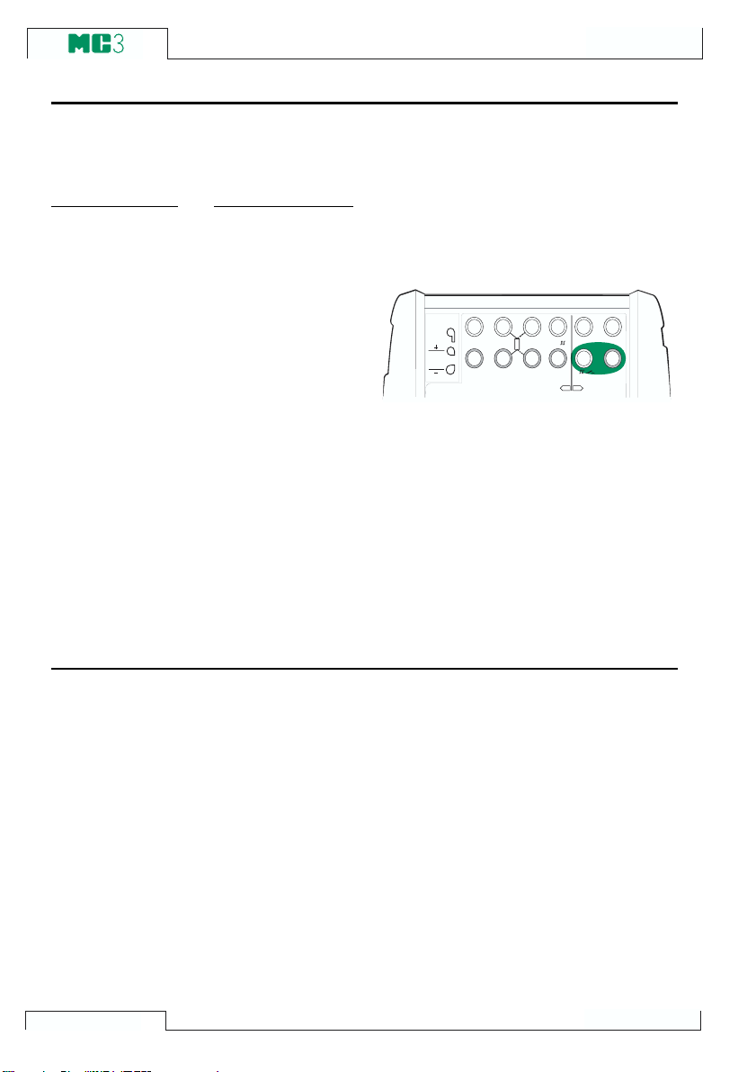
Voltage Measurement
Voltage measurement is possible with all MC3 models. Low Voltage measurement is
however only possible with MC3MF and MC3TE.
E section has terminals for voltage measurement within ±50V range. The ET section
The
has low voltage measurement terminals with a range of ±500mV. The ET section terminals are also used when measuring/simulating thermocouples using an external Reference Junction.
Required settings Options/description
Quantity Voltage
Funct/Port ET:LowV(mea), or E:V(meas)
Measuring Low Voltages
V , 1,
V , ,
O U T P U TM E A S U R E & S I M U L A T E M E A S U R E
E T E
2 - w x m t r
+ 2 4 V
1
m e a s / s i n k
Select Function/port ET:LowV(mea) and
choose a suitable unit. The following picture displays the active terminals.
MC3 displays the measured low voltage in
the selected window.
T / C I N T . R J
T / C O R E X T
W I R E S O N L Y
T / C , L o w V
4 - w m e a s
R , R T D
3 & 4 - w m e a s
34
Hint!
Low voltage measurement can be used for non-standard thermo-
couple measurement. You will see the measured temperature in
millivolts and need a table to convert the measured millivolt value to
corresponding temperature values. In this case, use copper extension cords to connect the non-standard thermocouple to MC3s terminals.
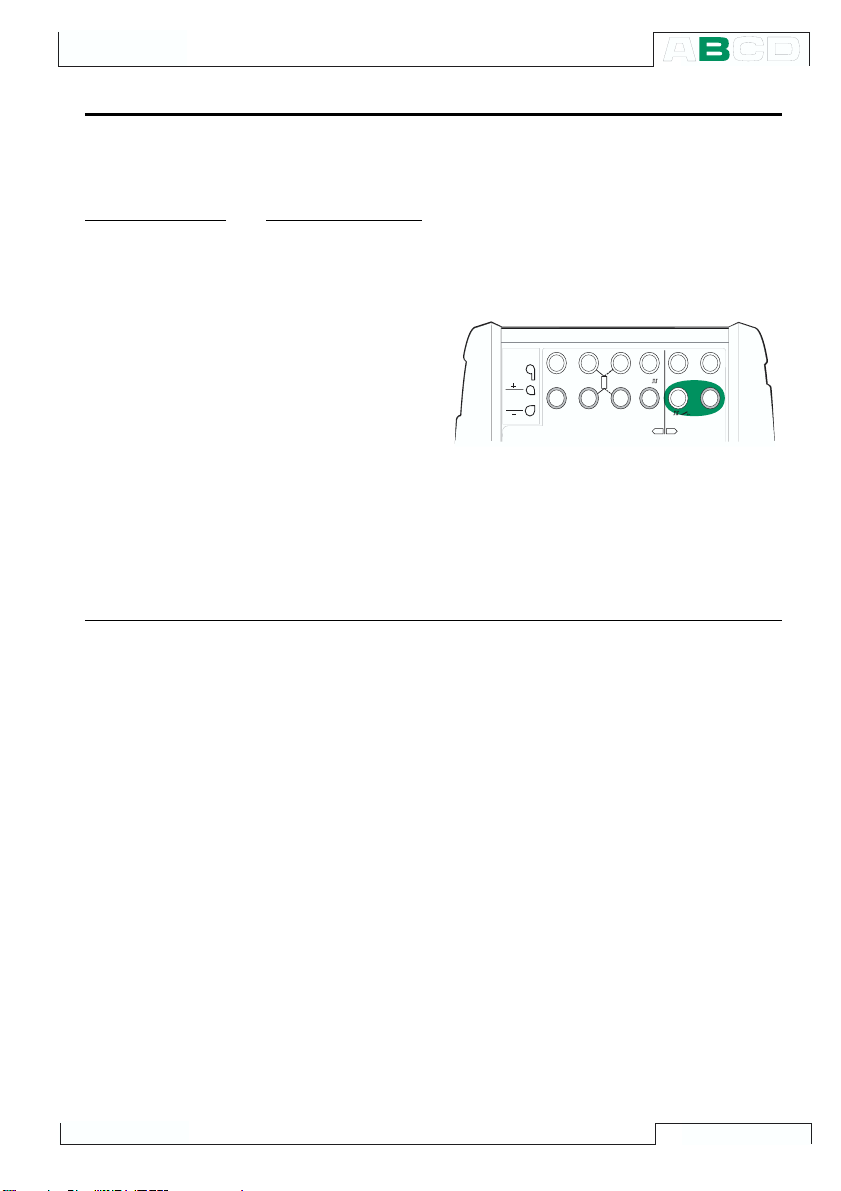
Measuring Voltages up to ±50 V
Select Function/port E:V(meas) and choose a suitable unit.
Measuring
Next
V , 1,
V , ,
O U T P U TM E A S U R E & S I M U L A T E M E A S U R E
E T E
2 - w x m t r
+ 2 4 V
1
m e a s / s in k
T / C IN T . R J
T / C O R E X T
W I R E S O N L Y
T / C , L o w V
4 - w m e a s
R , R T D
3 & 4 - w m e a s
MC3 displays the measured voltage in the selected window.
Warning!
Do not apply voltages higher than 50 V between any of MC3s
terminals.
Voltage Generation on page 49
Thermocouple Measurement (Temperature) on page 43
Calibration, see Part D.
35

Startup and Basic Operation
Resistance Measurement
Resistance measurement is possible with models MC3MF and MC3TE. Resistance measurement terminals are located in the ET section.
Required settings Options/description
Quantity Resistance
Funct/Port ET:R(meas)
The following picture displays the active
terminals:
V , 1,
V , ,
O U T P U TM E A S U R E & S IM U L A T E M E A S U R E
E T E
2 - w x m t r
+ 2 4 V
1
m e a s / s in k
T / C IN T . R J
T / C O R E X T
W I R E S O N L Y
T / C , L o w V
4 - w m e a s
R , R T D
3 & 4 - w m e a s
Note.
If the measured resistance value is infinite or very high (>4000ohm),
the text +OVER is displayed in the measuring window. This means
that the circuit is broken or the connection is wrong. Wrong connection may also cause erroneous reading, typically too low. If necessary, use the 2-wire ohm measurement to check the wiring before
final connection.
Next
RTD and Resistance Simulation on page 53
RTD Measurement (Temperature) on page 42
Calibration, see Part D.
The two leftmost terminals are used in 2wire systems. MC3 automatically checks
the connection and displays the found wiring system (2-wire, 3-wire or 4-wire) in the
measuring window. For more information
concerning wiring options, see Resistance
and RTD Measurement, Connections on
page 72.
36
Measuring
Switch State Sensing
Switch state sensing is possible with all MC3 models. The switch state detection terminals are located in the E section.
Required settings Options/description
Quantity Switch
Funct/Port E: Switch (selected automatically when the
corresponding Quantity setting is activated )
Also check the
Sound setting. The option
Change means that MC3 beeps every time
the switch changes its state. When using
options Open or Closed the sound is con-
tinuously on when the switch is open respectively closed.
The contact should be free of external potential. If this is not possible, use DC voltage within the range -10V to +30V. MC3
Hint!
Switch state detection may also be used for binary signal detection.
Next
Limit Switch Test on page 38
Calibration, see Part D.
shows voltages above approx. +1.5V as
open contact and voltages below approx.
+1.5V as closed contact.
V , 1,
V , ,
O U T P U TM E A S U R E & S I M U L A T E M E A S U R E
E T E
2 - w x m t r
+ 2 4 V
1
m e a s / s in k
T / C IN T . R J
T / C O R E X T
W I R E S O N L Y
T / C , L o w V
4 - w m e a s
R , R T D
3 & 4 - w m e a s
37

Startup and Basic Operation
Limit Switch Test
A limit switch test displays the opening and closing point of a limit
switch. MC3 supports limit switch testing of any type of limit switches
as long as MC3 is able to either measure or generate/simulate the
switchs input signal and is also capable of detecting the switch
state.
Notes.
This limit switch test is a restricted version compared to the limit
switch test available in Calibration Mode. This test gives you the
approximates of the latest opening and closing points and also the
current switch status. The limit switch test in Calibration Mode offers more accurate results and additionally, statistical data of repeated switch tests. More of the limit switch test in Calibration Mode
in Part D of this manual.
MC3 does not support limit switch testing when simulating resistance or an RTD sensor.
Performing the Limit Switch Test
Configure, e.g. Window 1 to either measure or generate/simulate the switchs input signal (Function keys D/Menu and
A/Window1Setup in Basic Mode) and
Window 2 for switch state detection (Function keys D/Menu and B/Window2Setup
in Basic Mode). It doesnt matter which window is assigned for which function as long
as both the switchs input signal and the
switch state are available for MC3.
Slowly change the switchs input signal and
watch how the Opened@ and Closed@
data is updated as the switch changes its
state.
3 0 . 0 1 . 2 0 0 0 1 3 : 3 5
1
V o l t a g e
E T : V o l t a g e G e n e r a t i o n
1 . 8 7 0 0 0
M e a s u r e m e n t V
2
S w i t c h
E : S w i t c h S e n s e
C l o s e d
O p e n e d @ V
C l o s e d @ V
C a l i b r a t i o n
M o d e
F i e l d
S t o p
R a m p i n g
V
1 . 8 6 7 1 2
1 . 2 9 9 9 0
0 . 9 8 5 4 9
M E N U
38

Measuring
Note.
The accuracy of the Opened @ and Closed @ values depend
greatly on the change rate of the switchs input signal.
Hint.
If you use MC3 to generate/simulate the switchs input signal, you
can use ramping to create changing input signals for the switch
under test.
Where to find more information when measuring a switchs input signal
Pressure Measurement on page 32
Voltage Measurement on page 34
Current Measurement on page 33
Thermocouple Measurement (Temperature) on page 43
RTD Measurement (Temperature) on page 42
Where to find more information when generating a switchs input signal
Voltage Generation on page 49
Current Generation on page 47
Thermocouple Simulation on page 54
Ramping on page 58
39
Startup and Basic Operation
Frequency Measurement
Frequency measurement is possible with all MC3 models.
The frequency measurement terminals are located in the
Required settings Options/description
Quantity Freq.
Funct/Port E: f(meas)
Also check the Unit setting.
MC3 compares the external potential
against an adjustable reference voltage
Trigger Level, range: -1+15V) when
(
measuring the frequency.
T / C IN T . R J
T / C O R E X T
W I R E S O N L Y
E section.
T / C , L o w V
R , R T D
3 & 4 - w m e a s
4 - w m e a s
V , 1,
V , ,
O U T P U TM E A S U R E & S I M U L A T E M E A S U R E
E T E
2 - w x m t r
+ 2 4 V
1
m e a s / s in k
40
Next
Switch State Sensing on page 37
Pulse Counting on page 41
Frequency Generation on page 51
Calibration, see Part D.
Measuring
Pulse Counting
Pulse counting is possible with all MC3 models. The pulse counter terminals are located
in the E section.
Required settings Options/description
Quantity Pulses
Funct/Port E: Pls(count)
Also check the Trigg.Edge setting.
MC3 compares the external potential
against an adjustable reference voltage
Trigger Level, range: -1 +15V) when
(
counting pulses.
The counter may be cleared (zeroed) by selecting
D/Menu, 6/Clear counter.
T / C IN T . R J
T / C O R E X T
W I R E S O N L Y
T / C , L o w V
4 - w m e a s
R , R T D
3 & 4 - w m e a s
V , 1,
V , ,
O U T P U TM E A S U R E & S I M U L A T E M E A S U R E
E T E
2 - w x m t r
+ 2 4 V
1
m e a s / s in k
Next
Frequency Measurement on page 40
Switch State Sensing on page 37
Pulse Generation on page 52
Calibration, see Part D.
41

Startup and Basic Operation
RTD Measurement (Temperature)
RTD measurement is possible with models MC3MF and MC3TE. RTD measurement terminals are located in the ET section.
Required settings Options/description
Quantity RTD-Temp.
Funct/Port ET:RTD(mea)
Sensor Type Available RTD sensors
The following picture displays the active
terminals:
V , 1,
V , ,
O U T P U TM E A S U R E & S I M U L A T E M E A S U R E
E T E
2 - w x m t r
+ 2 4 V
1
m e a s / s i n k
T / C I N T . R J
T / C O R E X T
W I R E S O N L Y
T / C , L o w V
4 - w m e a s
R , R T D
3 & 4 - w m e a s
Note.
If the measured resistance value is infinite or very high (> 4000
ohm), the text +OVER is displayed in the measuring window. This
means that the circuit is broken or the connection is wrong. Wrong
connection may also cause erroneous reading, typically too low. If
necessary, use the 2-wire ohm measurement to check the wiring
before final connection.
Next
RTD and Resistance Simulation on page 53
Thermocouple Measurement (Temperature) on page 43
Resistance Measurement on page 36
Calibration, see Part D.
The two leftmost terminals are used in 2wire systems. MC3 automatically checks
the connection and displays the found wiring system (2-wire, 3-wire or 4-wire) in the
measuring window. For more information
concerning wiring options, see Resistance
and RTD Measurement, Connections on
page 72.
42

Measuring
Thermocouple Measurement (Temperature)
Thermocouple measurement is possible with models MC3MF and MC3TE. Thermocouple
measurement terminals are located in the ET section.
Required settings Options/description
Quantity T/C-Temp
Funct/Port ET:TCi(mea) (for the internal Reference Junction), or
ET:TCx(mea) (for other RJ compensation methods)
Sensor Type Available thermocouples
Reference Junction Depends on the Function/Port setting.
See subsequent chapters.
Internal Reference Junction
To use the Internal Reference Junction,
select Function/Port ET:TCi(mea). The
Reference Junction compensation method
Internal is automatically selected.
V , 1,
V , ,
O U T P U TM E A S U R E & S IM U L A T E M E A S U R E
E T E
2 - w x m t r
+ 2 4 V
1
m e a s / s in k
T / C IN T . R J
4 - w m e a s
R , R T D
3 & 4 - w m e a s
T / C O R E X T
W I R E S O N L Y
T / C , L o w V
Additional information is found in chapter
Internal Reference Junction on page 68.
External Reference Junction
To use an External Reference Junction,
select Function/Port ET:TCx(mea) and
choose one of the available Reference
Junction compensation methods: Entered,
0°C or available RTD sensors.
V , 1,
V , ,
O U T P U TM E A S U R E & S I M U L A T E M E A S U R E
E T E
2 - w x m t r
+ 2 4 V
1
m e a s / s in k
T / C IN T . R J
4 - w m e a s
R , R T D
3 & 4 - w m e a s
T / C O R E X T
W I R E S O N L Y
T / C , L o w V
Additional information is found in chapter
External Reference Junction on page 69.
43

Next
Startup and Basic Operation
Warning!
If you connect an RTD sensor to the ET sections
R, RTD con-
nectors, there is no galvanic isolation between the thermocouple and the RTD sensor.
Thermocouple Simulation on page 54
RTD Measurement (Temperature) on page 42
Voltage Measurement on page 34
Calibration, see Part D.
Problems with thermovoltage measurement? See Error situations
on page 71.
44

Generating/Simulating
Generating/Simulating
General
MC3 is capable to perform the following generation/simulation functions:
· Voltage generation
· Current generation
· Frequency and pulse generation
· Thermocouple simulation
· RTD and resistance simulation
Generation/simulation in Basic Mode require that you first select
the Window to be used (Commands: Start with
tinue either with A/Window1Setup or B/Window2Setup). Each
generation/simulation has its own unique 1/Quantity and 2/Func-
tion/Port settings in their windows menu. The other window menu
settings (generation/simulation unit etc.) refine the generation/simulation characteristics.
Because all generations/simulations are not available in all MC3
models, the presentation of each generation/simulation include a
description of MC3 models supporting this generation/simulation.
The required section for the generation/simulation is also mentioned.
If the section is not included in your MC3, the
2/Function/Port settings needed for the generation/simulation are
not available as choices in the pop-up lists.
Each generation/simulation also has at least one picture with a circle
around some of MC3s terminals, like the one below.
D/Menu and con-
1/Quantity and
V , 1,
V , ,
O U T P U TM E A S U R E & S I M U L A T E M E A S U R E
E T E
2 - w x m t r
+ 2 4 V
1
m e a s / s i n k
T / C I N T . R J
T / C O R E X T
W I R E S O N L Y
T / C , L o w V
4 - w m e a s
R , R T D
3 & 4 - w m e a s
The circle indicates active terminals for each
2/Function/Port setting in the window menu.
1/Quantity and
45

Startup and Basic Operation
Warnings!
When selecting a generation/simulation function, MC3 always
starts with zero output (not when simulating a resistance). This
is done to prevent damages in the connected instrument.
Be careful when increasing the generated/simulated signal. If
an instrument that cannot withstand the generated signal is
connected to MC3, the instrument may get seriously damaged.
Changing the Value of the Generated/Simulated Signal
Move the field indicator on the display until it surrounds the value of
generated/simulated signal (use the B/Field Function Key or the
cursor keys).
Enter the new value using the numeric keys. You may cancel the
editing by pressing the A/Cancel Function Key. The C/çDelete
Function Key removes the rightmost digit.
Accept the new value by pressing either the
Function Key.
key or the D/OK
46
Note.
The dual function of the keys:
generation field. The keys only represent numbers.
, and is not available in a

Generating/Simulating
Current Generation
Current generation is possible with all MC3 models. MC3 can generate current both with
the E and the ET section. Additionally the E section can be used both in source and sink
mode.
Required settings Options/description
Quantity Current
Funct/Port ET:I(gen) or E:I(control)
Using the ET sections output terminals
When generating current from the ET
sections output terminals, select Funct/
Port option ET:I(gen). The following pic-
ture displays the active terminals:
Notes.
If you are simultaneously using the ET sections output terminals
and some of the ET sections measuring terminals, there is no galvanic isolation between the measuring circuit and the current generation.
The voltage between the output connectors of the ET section is
limited to ±15 Volts. There is no sinking possibility in the ET section.
T / C IN T . R J
T / C O R E X T
W I R E S O N L Y
T / C , L o w V
4 - w m e a s
R , R T D
3 & 4 - w m e a s
V , 1,
V , ,
O U T P U TM E A S U R E & S IM U L A T E M E A S U R E
E T E
2 - w x m t r
+ 2 4 V
1
m e a s / s in k
Using the E sections output terminals
When generating current from the E
sections output terminals, you can either
use MC3s internal 24V supply (source
mode) or use an external supply and let
MC3 control the current (sink mode).
Based on the terminals in use, MC3 automatically selects either source or sink mode.
Active terminals in source mode (below):
V , 1,
V , ,
O U T P U TM E A S U R E & S I M U L A T E M E A S U R E
E T E
2 - w x m t r
1
+ 2 4 V
m e a s / s in k
T / C IN T . R J
T / C O R E X T
W I R E S O N L Y
T / C , L o w V
4 - w m e a s
R , R T D
3 & 4 - w m e a s
Active terminals in sink mode (below):
V , 1,
O U T P U TM E A S U R E & S I M U L A T E M E A S U R E
E T E
2 - w x m t r
+ 2 4 V
1
m e a s / s in k
V , ,
T / C IN T . R J
T / C O R E X T
W I R E S O N L Y
T / C , L o w V
4 - w m e a s
R , R T D
3 & 4 - w m e a s
47

Startup and Basic Operation
Notes applying to both the ET:I(gen) and the E:I(control) ports:
Check the polarity of your connections. The arrows in the previous
pictures describe the correct flow of current.
If the loop resistance of the external circuit is too high or infinite, the
message O.LOAD is displayed until the load is reasonable.
Warnings!
Make sure that you dont exceed the maximum current allowed
by the instrument under test.
If you open the mA generation loop, MC3 tries to maintain the
current by increasing the output voltage. If you then close the
loop again, the current is first too high, but returns quickly to
the correct level. If this current peak could damage the components of the loop, make sure that the loop will not open or protect it against overcurrent. For the same reason, always enter
0mA output before connecting the loop.
48
Next
Current Measurement on page 33
Special Generations on page 56
Calibration, see Part D.

Generating/Simulating
Voltage Generation
Voltage generation is possible with models MC3MF and MC3TE. The ET section has terminals for voltage generation within ±12V range and terminals for low voltage sensor simulation with the range ±500mV. The low voltage terminals are also used when measuring/
simulating thermocouples using an external Reference Junction.
Required settings Options/description
Quantity Voltage
Funct/Port ET: V(gen) or ET:LowV(sim)
Generating Voltages up to ±12 V
Select Function/port ET: V(gen) and
choose a suitable unit.
MC3 displays both the set value and the
V , 1,
V , ,
O U T P U TM E A S U R E & S IM U L A T E M E A S U R E
E T E
2 - w x m t r
+ 2 4 V
1
m e a s / s in k
T / C IN T . R J
4 - w m e a s
R , R T D
3 & 4 - w m e a s
T / C O R E X T
W I R E S O N L Y
T / C , L o w V
internally measured value for the generated
voltage in the selected window. Max. output current depends on the voltage level
as follows:
10 mA if the Voltage is within ±10V or
3 mA if the Voltage is outside of ±10V.
Low Voltage Generation
Select Function/port ET:LowV(sim) and
choose a suitable unit. The max. output
current is 5mA.
V , 1,
V , ,
O U T P U TM E A S U R E & S I M U L A T E M E A S U R E
E T E
2 - w x m t r
+ 2 4 V
1
m e a s / s in k
T / C IN T . R J
4 - w m e a s
R , R T D
3 & 4 - w m e a s
T / C O R E X T
W I R E S O N L Y
T / C , L o w V
MC3 displays both the set value and the
internally measured value for the generated
voltage in the selected window.
49

Startup and Basic Operation
Note.
If the resistance of the external circuit in voltage generation is very
low (obvious short circuit), the message O.LOAD is displayed until
the load is reasonable.
Hint!
Low voltage generation can be used when calibrating instruments
with millivolt input. You can use it also to simulate special thermocouples not defined in MC3. If you simulate a thermocouple in millivolt mode, you must convert from temperature to millivolts manually.
Warning:
If you short circuit the voltage output, MC3 tries to maintain the
voltage by increasing the output current. If you then remove
the short circuit, the voltage is first too high, but returns quickly
to the correct level. If this voltage peak could damage the components of the circuit, make sure that the circuit can not be
shorted or protect the circuit against overvoltage. For the same
reason, always enter 0V output before connecting the circuit.
50
Next
Voltage Measurement on page 34
Thermocouple Simulation on page 54
Special Generations on page 56
Calibration, see Part D.

Generating/Simulating
Frequency Generation
Frequency generation is possible with models MC3MF and MC3TE. The frequency generation terminals are located in the ET section.
Required settings Options/description
Quantity Freq.
Funct/Port ET: f(gen)
Also check the Unit and Waveform settings.
MC3 generates sine or square wave with
given amplitude and frequency. Sine can
only be generated above 40 Hz. When
generating a square wave, the output DClevel can be set to symmetric or all positive.
The amplitude (V
to 12V.
) setting range is: 0.01V
pp
T / C IN T . R J
T / C O R E X T
W I R E S O N L Y
T / C , L o w V
4 - w m e a s
R , R T D
3 & 4 - w m e a s
V , 1,
V , ,
O U T P U TM E A S U R E & S IM U L A T E M E A S U R E
E T E
2 - w x m t r
+ 2 4 V
1
m e a s / s in k
Next
Pulse Generation on page 52
Frequency Measurement on page 40
Special Generations on page 56
Calibration, see Part D.
51
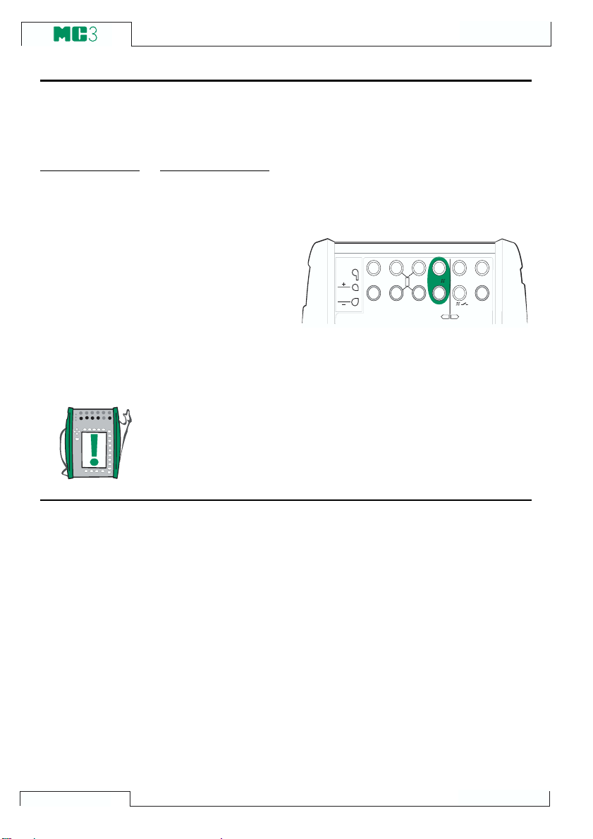
Startup and Basic Operation
Pulse Generation
Pulse generation is possible with models MC3MF and MC3TE. The pulse generation terminals are located in the ET section. Pulse generation is similar to square wave frequency
output, but it generates a predefined count of all positive or symmetric pulses.
Required settings Options/description
Quantity Pulses
Funct/Port ET: Pls(gen)
Also check the Polarity setting.
Enter the amount of pulses MC3 should
generate in the pulse generation window.
Also enter the amplitude and frequency
to be used.
The pulse generation starts immediately
after the amount of pulses value is entered.
Note.
If you change the frequency after the pulse generation has started,
the frequency is adjusted during the current cycle, but the frequency
is not correct until the next cycle.
Next
Frequency Generation on page 51
Pulse Counting on page 41
Special Generations on page 56.
T / C IN T . R J
T / C O R E X T
W I R E S O N L Y
T / C , L o w V
2 - w x m t r
4 - w m e a s
R , R T D
3 & 4 - w m e a s
V , 1,
V , ,
O U T P U TM E A S U R E & S IM U L A T E M E A S U R E
E T E
+ 2 4 V
1
m e a s / s in k
52
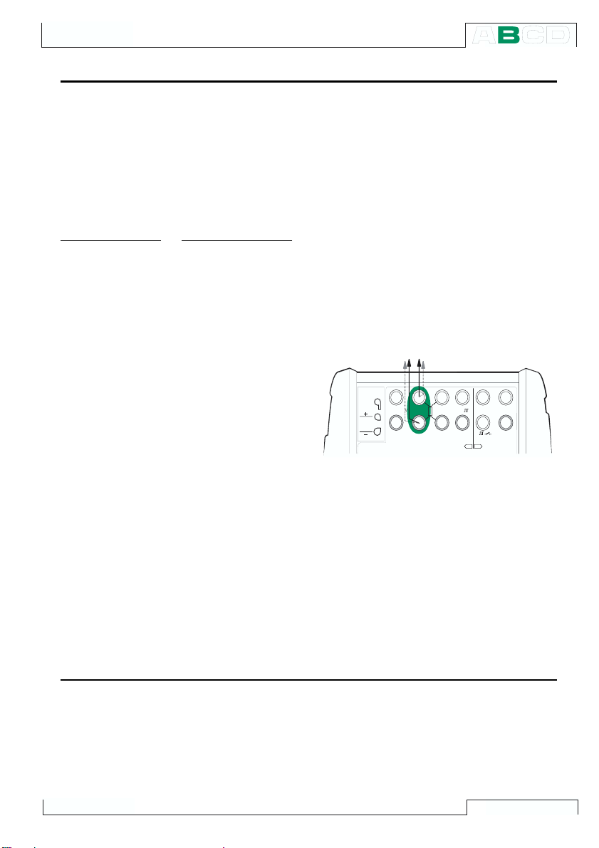
Generating/Simulating
RTD and Resistance Simulation
MC3 mimics the RTD or the resistor to be measured by the instrument under test. The
instrument under test generates the current for the resistance measurement. MC3 controls the voltage across its terminals so that the resistance (voltage to current ratio) corresponds to the simulated temperature or resistance. MC3 can simulate resistance between 1 to 4000 ohm.
MF
Voltage measurement is possible with models MC3
simulation terminals are located in the ET section.
Required settings Options/description
Quantity RTD-Temp. (for RTD simulation)
Resistance (for resistance simulation)
Funct/Port ET:RTD(sim) (for RTD simulation)
ET:R(sim) (for resistance simulation)
Sensor Type Available RTD sensors. Only needed
when doing RTD simulation.
The correct resistance value is between the
resistance simulation terminals of the calibrator. Use of 2-, 3- or 4-wire connection is
up to the receiver instrument. Use only the
two leftmost
R,RTD terminals with every
wiring option. Connect the possible third
and fourth wire according to the requirements of the connected instrument, but use
only the two leftmost R,RTD terminals.
and MC3TE. RTD and resistance
V , 1,
V , ,
O U T P U TM E A S U R E & S IM U L A T E M E A S U R E
E T E
2 - w x m t r
+ 2 4 V
1
m e a s / s in k
T / C IN T . R J
T / C O R E X T
W I R E S O N L Y
T / C , L o w V
4 - w m e a s
R , R T D
3 & 4 - w m e a s
Notes.
In RTD and resistance simulation MC3
monitors the resistance measurement current. If the current is too high, it cannot
simulate the right resistance value. In that
case it shows the message H.CURR.
Respectively, if the measurement current
is so low that it may affect the accuracy,
the message L.CURR is displayed.
Next
Thermocouple Measurement (Temperature) on page 43
RTD Measurement (Temperature) on page 42
Resistance Measurement on page 36
Special Generations on page 56
Calibration, see Part D.
Accurate operation of the simulation electronics requires that the current supplied
by the instrument under test does not vary
rapidly. The simulation result is not accurate if the instrument under test uses AC
current. If the instrument under test uses
pulsed measurement current it should wait
a few milliseconds before starting the measurement after setting the current.
53
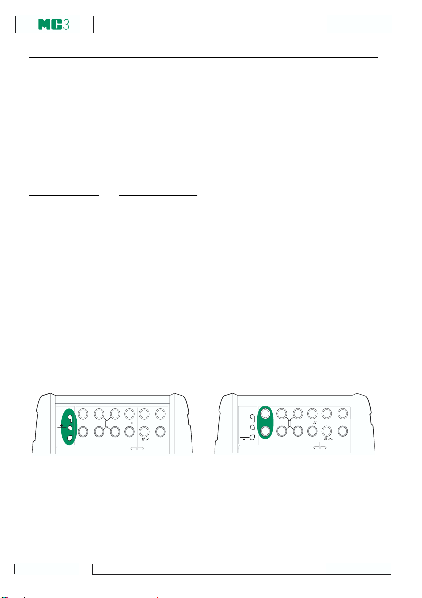
Startup and Basic Operation
Thermocouple Simulation
MC3 is able to mimic a thermocouple at given temperatures. This property is called thermocouple simulation. It enables checking and calibration of temperature indicators, recorders, transmitters and other equipment related to temperature measurement with a
thermocouple probe.
In thermocouple simulation the original thermocouple is disconnected from the instrument under test and replaced with MC3. To the instrument under test MC3 appears as a
thermocouple at the given temperature.
MF
Voltage measurement is possible with models MC3
tion terminals are located in the ET section.
Required settings Options/description
Quantity T/C-Temp
Funct/Port ET:TCi(sim) (for the internal Reference Junction), or
ET:TCx(sim) (for other RJ compensation methods)
Sensor Type Available thermocouple types
Reference Junction Depends on the Function/Port setting.
See subsequent chapters.
and MC3TE. Thermocouple simula-
Internal Reference Junction
The use of MC3s Internal Reference Junction is optional. To use the Internal Reference Junction, select Function/Port
ET:TCi(sim). The Reference Junction
compensation method Internal is automatically selected.
+ 2 4 V
V , 1,
V , ,
O U T P U TM E A S U R E & S IM U L A T E M E A S U R E
E T E
2 - w x m t r
1
m e a s / s in k
T / C IN T . R J
4 - w m e a s
R , R T D
3 & 4 - w m e a s
T / C O R E X T
W I R E S O N L Y
T / C , L o w V
Additional information is found in chapter
Internal Reference Junction on page 68.
54
External Reference Junction
To use an External Reference Junction,
select Function/Port ET:TCx(sim) and
choose one of the available Reference
Junction compensation methods: Entered,
0°C or available RTD sensors.
V , 1,
V , ,
O U T P U TM E A S U R E & S I M U L A T E M E A S U R E
E T E
2 - w x m t r
+ 2 4 V
1
m e a s / s in k
T / C IN T . R J
4 - w m e a s
R , R T D
3 & 4 - w m e a s
T / C O R E X T
W I R E S O N L Y
T / C , L o w V
Additional information is found in chapter
External Reference Junction on page 69.

Generating/Simulating
Notes.
If the resistance of the external circuit in thermocouple simulation is
very low (obvious short circuit), the message O.LOAD is displayed
until the load is reasonable.
Check that the instrument under test is set for the same thermocouple type as selected in MC3. If the type is not one of the available types, you should simulate in millivolt mode and convert from
temperature to millivolts manually. More information concerning
millivolt generation is in chapter Voltage Generation on page 49.
Wire-wound thermocouple temperature indicators and recorders are calibrated with known loop resistance, commonly ten or
twenty ohms. The required resistance of the conductors is usually
marked on the device. When calibrating such a device, tune the
loop resistance to the nominal value with an additional resistor.
Use MC3s 2-wire resistance measurement to tune the loop resistance of a wire wound device. Short circuit the measuring device
for the time of resistance measurement. The resistance measurement may damage the device, if you do not install the short circuit.
For more information on resistance measurement, see chapter
Resistance Measurement on page 36.
Warning!
If you short circuit the thermocouple simulation output, MC3
tries to maintain the voltage by increasing the output current.
If you then open the output again, the voltage is first too high,
but returns quickly to the correct level. If this voltage peak could
damage the components of the circuit, make sure that the circuit can not be shorted or protect the circuit against overvoltage. For the same reason, always enter 0°C output before connecting the circuit.
If you connect an RTD sensor to the ET sections R, RTD connectors, there is no galvanic isolation between the thermocouple and the RTD sensor.
Next
Thermocouple Measurement (Temperature) on page 43
RTD and Resistance Simulation on page 53
Special Generations on page 56
Calibration, see Part D.
Problems with thermovoltage simulation? See Error situations on page 71.
55
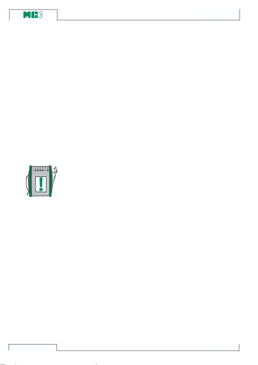
Startup and Basic Operation
Special Generations
Manual change of generated signals is sometimes a restriction.
Therefore MC3 includes Stepping and Ramping as standard utilities for creating automatically alternating output signals (special
generations).
To be able to start the definition of a special generation, a suitable
generation/simulation field has to be active in the Basic Mode Window. If a generation/simulation is not started, select
either A/Window1Setup or B/Window2Setup to configure a
generation/simulation. For more information on how to configure a
generation/simulation, see chapter Generating/Simulating on page
45 and its subchapters.
Notes.
Only one of the special generations may be active at a given time.
Special generations are available only in Basic Mode.
D/Menu and
56
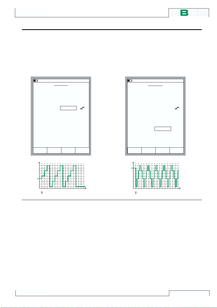
Stepping
Special Generations
Open the window setup menu for the generation/simulation quantity that you want to
configure a Stepping function for (D/Menu
and either A/Window1Setup or B/Win-
dow 2Setup ). Choose 3/Step,Ramp and
1/Step in the next menu.
3 0 . 0 1 . 2 0 0 1 1 3 : 3 5
S T E P P I N G
Q u a n t i t y
P o r t
S t e p p i n g M o d e
S t e p T i m e
R e p e a t s
0 = c o n t i n u o u s
S t a r t i n g P o i n t
S t e p S i z e
N u m b e r o f S t e p s
D i v i s i o n o f S t e p s
R a n g e
C u r r e n t , m A
1 2
1 1
1 0
9
8
10- 1 5 1 0 1 4
S t a r t
1 0 0 %
0 %
F i e l d
C u r r e n t
E T : I ( g e n )
U p
1 . 0 0
3
F r o m p r e s e n t
1 . 0 0
4
L i n e a r
8 . 0 0 0 0
1 2 . 0 0 0 0
S t o p
E d i t
R a m p i n g
s
m A
m A
S t a r tC a n c e l
T i m e , s
Configure the Stepping settings according
to your needs. The following pictures are
examples of stepping configurations. The
graph below the configuration window displays the result of the settings.
3 0 . 0 1 . 2 0 0 1 1 3 : 3 6
S T E P P I N G
Q u a n t i t y
P o r t
S t e p p i n g M o d e
S t e p T i m e
R e p e a t s
0 = c o n t i n u o u s
S t a r t i n g P o i n t
S t e p S i z e
N u m b e r o f S t e p s
D i v i s i o n o f S t e p s
R a n g e
C u r r e n t , m A
1 2
1 1
1 0
9
8
10- 1 5 1 0 1 4
S t a r t
1 0 0 %
0 %
F i e l d
C u r r e n t
E T : I ( g e n )
U p / D o w n
0 . 5 0
0
F r o m 0 %
1 . 5 0
- - - - - - L i n e a r
8 . 0 0 0 0
1 2 . 0 0 0 0
S t o p
R a m p i n g
s
m A
m A
S t a r tC a n c e l E d i t
T i m e , s
Note that because of the
Starting point
setting, the first repeat of the leftmost example is limited to a small starting step and
only two full steps. Generally: if the stepping settings limit the first repeat to only a
fraction of a full repeat it is still calculated
as one repeat.
You may enter either the
Number of Steps. Because these values
Step Size or the
depend on each other, the value of the other
field is calculated whenever you make any
changes. Also, you can only enter an integer as the Number of Steps value. If you
enter a step size that results in a non-inte-
ger value for the Number of Steps field,
MC3 displays a dashed line instead of a
value for the Number of Steps field. This
indicates that the size of the step that
reaches the 100 % range limit is smaller
than the defined step size. See the
rightmost example.
To stop stepping press the function key C/
StopStepping. This applies for both a
continuous stepping (Repeats field set to
zero) and a stepping with a predetermined
amount of repeats (max. value 65535).
57
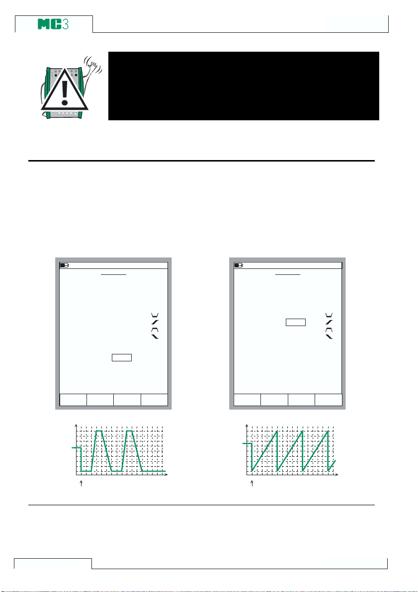
Ramping
s
s
Startup and Basic Operation
Warning!
Do not configure the range settings so that they exceed the
allowed input range of the connected instrument. MC3 determines the limits of the range settings based on the selected
quantity and port, not the connected instrument.
Open the window setup menu for the generation/simulation quantity that you want to
configure a Ramping function for (D/Menu
and either A/Window1Setup or B/Win-
dow 2Setup ). Choose 3/Step,Ramp and
2/Ramp in the next menu.
3 0 . 0 1 . 2 0 0 1 1 3 : 3 8
R A M P I N G
Q u a n t i t y
P o r t
W a i t i n 0 %
R i s e T i m e
W a i t i n 1 0 0 %
F a l l T i m e
R e p e a t s
0 = c o n t i n u o u s
R a n g e
C u r r e n t , m A
1 6
1 4
1 2
1 0
8
S t a r t
C u r r e n t
E T : I ( g e n )
2
1
1
2
2
0 %
8 . 0 0 0 0
1 0 0 %
1 6 . 0 0 0 0
S t o p
F i e l d
R a m p i n g
10- 1 5 1 0 1 4
s
s
s
s
m A
S t a r tC a n c e l E d i t
T i m e ,
Configure the ramping settings according
to your needs. The following pictures are
examples of ramping configurations. The
graphs presented after the configuration
windows display the result of the settings.
3 0 . 0 1 . 2 0 0 1 1 3 : 3 9
R A M P I N G
Q u a n t i t y
P o r t
W a i t i n 0 %
R i s e T i m e
W a i t i n 1 0 0 %
F a l l T i m e
R e p e a t s
0 = c o n t i n u o u s
R a n g e
C u r r e n t , m A
1 6
1 4
1 2
1 0
8
10- 1 5 1 0 1 4
S t a r t
1 0 0 %
0 %
F i e l d
C u r r e n t
E T : I ( g e n )
0
5
0
0
0
8 . 0 0 0 0
1 6 . 0 0 0 0
S t o p
R a m p i n g
s
s
s
s
m A
S t a r tC a n c e l E d i t
T i m e ,
To stop ramping press the function key
C/Stop Ramping. This applies for both a
continuous ramping (Repeats field set to
58
zero) and a ramping with a predetermined
amount of repeats (max. value 65535).

Special Generations
Note.
MC3 actually makes the ramp in small steps. The steps are as small
as possible, slower ramps use smaller steps.
Warning!
Do not configure the range settings so that they exceed the
allowed input range of the connected instrument. MC3 determines the limits of the range settings based on the selected
quantity and port, not the connected instrument.
59

Startup and Basic Operation
(Empty)
60

Configurations and
Additional Information
Things discussed in Part C:
· How to configure MC3 to suit
your requirements.
· Additional information: Useful
during pressure measurement,
thermocouple measurement/
simulation and resistance/RTD
measurement/simulation.

Advanced Operation and Configuration
2 9 . 0 1 . 2 0 0 1 1 0 : 3 0
N e t F r e q u e n c y
B a c k l i g h t P o w e r
N o r m a l
5 0 H z
T e m p e r a t u r e U n i t
T e m p e r a t u r e S c a l e
° C
I T S 9 0
S E T T I N G S
C l o s e
P a g e
N e x t
E d i t
Configuring the Calibrator
A group of settings are available in MC3s Others menus Mainte-
nance option. The following chapters tell how you can change them
and what the default settings are.
Settings
The settings window has two pages. To open the settings window
starting from Basic Mode, press D/Menu, C/Others and 1/Set-
tings. The leftmost picture is the settings page that opens first.
2 9 . 0 1 . 2 0 0 1 1 0 : 2 9
S E T T I N G S
D a t e F o r m a t
T i m e F o r m a t
L a n g u a g e
A u t o - o f f D e l a y s ( 0 = n e v e r ) [ m i n ]
C a l i b r a t o r
B a c k l i g h t
S o u n d V o l u m e s
K e y C l i c k
d d . m m . y y y y
h : m m 2 4 h
E n g l i s h
0
5
L o w
62
N e x t
C l o s e
You can scroll between the pages using the
P a g e
E d i t
B/NextPage Function
Key.
Note.
All changes in settings become valid immediately.

Configuring the Calibrator
Date Format
A drop down list of available date formats:
dd.mm.yyyy, yyyy.mm.dd and mm.dd.yyyy.
The default format is dd.mm.yyyy.
Time Format
A drop down list of available time formats.
24 hour format: h:mm
12 hour format: h:mm am/pm.
The default setting is the 24 hour format.
Language
A drop down list of available User Interface
languages. The default language is English.
Auto-Off Delay for the Calibrator
Wait time before auto power off is executed.
The default setting is 0 (never).
Auto-Off Delay for the Display Backlight
Wait time before the display light is automatically switched off.
The default setting is 5 min.
Setting the time to zero disables display
backlight auto-off.
Sound Volume Setting
The sound of the key click may be set to
one of the following values: Off, Low, Medium or High.
Line Frequency
Select the setting that suits the local line
frequency (50 or 60 Hz).
Note that wrong line frequency setting affects the accuracy of MC3.
The default setting is 50 Hz.
Display Backlight Power
Select the backlight power from the available options:
· Economy
· Normal
· Efficient
The default setting is Economy.
Temperature Unit
Select either °C (Centigrade) or °F (Fahrenheit) as the temperature unit.
The default setting is °C.
Temperature Scale
MC3 supports the use of both international
temperature scales: ITS90 and the older
IPTS68. Select which one of them is in use.
The default setting is ITS90.
63

Advanced Operation and Configuration
Setting Time and Date
To change the time and date (starting from Basic Mode), press
D/Menu, C/Others, 2/Maintenance and 2/Time/Date.
Notes.
The date must always be given in dd.mm.yyyy format no matter
what the configured date format is.
The time must always be given in the 24 hour format no matter
what the configured time format is.
The date and time will be updated when you press the
Function Key.
2 9 . 0 1 . 2 0 0 1 1 0 : 3 2
T I M E / D A T E S E T T I N G S
D a t e ( d d . m m . y y y y )
T i m e ( h h : m m : s s )
C a n c e l A c c e p tE d i t
2 9
0 1
2 0 0 1
1 0
3 2
2 2
D/Accept
64

Additional Information
Additional Information
Most of the measurements, generations and simulations presented
in this manual are straight forward: Just make the required window
settings and connect the instrument under test in the active terminals and thats it!
Some cases require additional settings and things to check before
you can be certain that the measurement, generation or simulation
works as expected. A typical example of this is temperature measurement using a thermocouple. It is not enough to select the correct quantity and port in MC3. The Sensor type and the Reference
Junction Mode have to be correct too. Wrong settings give erroneous results.
Whenever this additional information may be of use in a measurement, generation or simulation, text describing the function refers
to one of the following chapters. An experienced user need not jump
to read this supplemental text, but for a beginner we highly recommend it.
The main subjects described here are:
Things to Consider when Measuring Pressure on page 66,
Thermocouple Measurement/Simulation, Connections and
Troubleshooting on page 68,
Resistance and RTD Measurement, Connections on page 72
and
Current Measurement Parallel to a Test Diode, Connections
on page 73.
Parallel Functions in MC3 on page 74
65

Advanced Operation and Configuration
Things to Consider when Measuring Pressure
General
MC3 measures pressure with its internal gauge pressure input, if
present. Additionally, if the barometric option is present, the
measurement results of the gauge pressure input can also be shown
as absolute pressure.
Pressure Type
Every pressure measurement is in fact a pressure difference measurement: a given pressure value is compared against a reference
pressure. In certain cases the reference pressure has a special
meaning (like the atmospheric pressure) and the pressure measurements compared against these points are given a special name:
· Absolute pressure measurement uses vacuum as the refer-
ence pressure.
· Barometric pressure (or atmospheric pressure) is the ab-
solute pressure of the surrounding atmosphere. It is specially
titled because of its importance.
· Gauge pressure measurement uses the atmospheric pres-
sure as the reference. Gauge pressure may be zero, negative
or positive. Most of MC3s pressure inputs actually measure
gauge pressure although they may be used for measuring other
pressure types too.
· Differential pressure measurement requires a special dif-
ferential pressure module that has an input available for both
the reference pressure and the given pressure.
To be able to measure absolute pressure with MC3s gauge pressure input, you need the barometric pressure option. Certain high
pressure inputs may approximate absolute pressure measurement
by adding an entered barometric pressure to the measured gauge
pressure.
Always ensure that the pressure type setting of your pressure
measurement is what you intended it to be. The pressure type
setting is crucial for getting meaningful pressure measurement
results.
66

Additional Information
Pressure Inputs and their Naming Conventions
MC3s software refer to pressure inputs as follows:
Port: Input Name, e.g. P1: PR2C
which means that there is a pressure input in port P1 with a -1 to
2bar (-14.5 to 30psi) gauge pressure range.
The names of pressure inputs always start with the letters PR. The
names also include numbers and possible additional letters as follows:
1. The number defines the max. nominal pressure in the SI pres-
sure unit bar.
2. If there is an additional letter C, the pressure input is a com-
pound input with an ability to also measure negative gauge
pressures.
Examples: Name Max. nominal pressure in psi
PR2C -1 2 bar -14.5 30
PR160 0 160 bar 0 2400
Square Rooting
Pressure transmitters or converters used for flow measurement often have square rooting character. To enable correct percentage
error calculation of square rooting transmitters, select square rooting as the Transfer Function.
Square rooting is required when entering instrument data for a pressure instrument (see Part D, Calibration). Standard pressure measurement in Basic Mode does not require any Transfer Function
information.
67
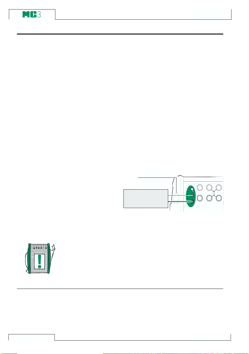
Advanced Operation and Configuration
Thermocouple Measurement/Simulation, Connections and
Troubleshooting
To accurately measure the thermovoltage caused by the temperature to be measured, the second thermovoltage caused by the Reference Junction needs to be compensated. This is done using one
of the Reference Junction compensation methods described in the
subsequent chapters.
The Reference Junction compensation method has to be chosen
both when measuring and simulating thermocouples.
Internal Reference Junction
If the measuring/simulating port is set to
the Internal Reference Junction
(ET:TCi(mea) or ET:TCi(sim)), MC3 auto-
matically selects the Internal Reference
Junction compensation method. No other
Reference Junction compensation methods are available unless the measuring/
simulating port is changed.
Connection when measuring/simulating thermovoltage using Internal
Reference Junction Mode:
T / C m a t e r i a l s
( T / C , e x t e n s i o n o r
c o m p e n s a t i o n w i r e s )
T / C s e n s o r
o r a
T / C IN T . R J
T / C IN T . R J
T / C O R E X T
T / C O R E X T
W I R E S O N L Y
W I R E S O N L Y
T / C s i g n a l r e c e i v e r
T / C , L o w V
M E A S U R E & S I M U L A T E
4 - w m e a s
R , R T D
3 & 4 - w m e a s
See also
68
Note.
The range of the Internal Reference Junctions temperature com-
pensation is -10 +50°C (14 122 °F).
External Reference Junction on page 69
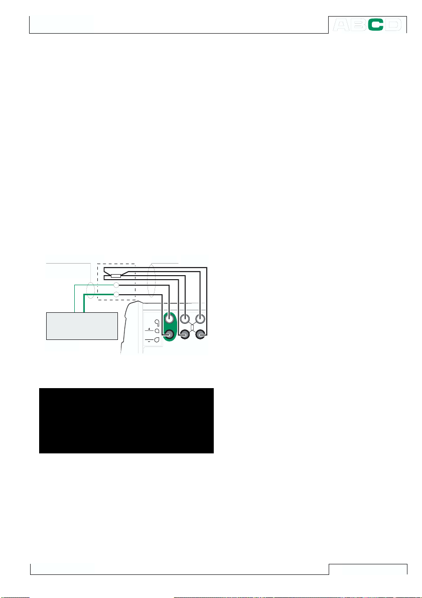
Additional Information
External Reference Junction
When using an external Reference Junction, MC3 measures or simulates the
thermovoltage using the T/CLowV terminals in the ET section. If the measuring/simulating port is set to the External Reference Junction (ET: TCx(mea) or ET: TCx(sim)),
the following Reference Junction compensation methods are available:
RTD sensor:
To be used when:
· The Reference Junction temperature is
measured using an RTD sensor connected to MC3s RTD terminals.
Connection when measuring/simulating
thermovoltage using Reference Junction compensation method
T / C m a t e r i a l s C o p p e r
T
r e f
T / C s e n s o r
o r a
T / C s i g n a l r e c e i v e r
RTD sensor:
T / C IN T . R J
T / C , L o w V
T / C , L o w V
T / C O R E X T
W IR E S O N LY
M E A S U R E & S IM U L A T E
4 -w m e a s
R , R T D
3 & 4 -w m e a s
Warning!
If you connect an RTD sensor to the ET
inputs
R, RTD connectors, there is no
galvanic isolation between the thermocouple and the RTD sensor.
0°C:
To be used when:
· The Reference Junction temperature is
fixed to 0°C (using, e.g. ice) and MC3
is not used for measuring the Reference
Junction temperature.
· The Reference Junction temperature is
controlled with 0°C set point.
· A compensation box is used and the
Reference Junction temperature setting
is 0°C.
· There is no Reference Junction compensation in the measuring/simulation circuit but 0°C is a good enough approximation.
Entered:
To be used when:
· The Reference Junction temperature is
fixed to a temperature that differs from
0°C.
· The Reference Junction temperature is
controlled and the controllers set point
is not 0°C. Note: this method is of use
only if the accuracy of the controller is
better than MC3s own Reference Junction.
· A compensation box is used and the
Reference Junction temperature setting
is other than 0°C.
· There is no Reference Junction compensation in the measuring/simulation circuit, but you want to manually enter another Reference Junction temperature
than 0°C.
69

Advanced Operation and Configuration
Connection when measuring/simulating thermovoltage using a temperature
controller and Reference Junction
compensation method Entered (also
RJ-mode 0°C):
T e m p e r a t u r e
C o n t r o l l e r
T / C s e n s o r
o r a
T / C s i g n a l r e c e i v e r
T
r e f
T / C m a t e r i a l s
T / C IN T . R J
T / C O R E X T
W IR E S O N LY
T / C , L o w V
T / C , L o w V
M E A S U R E & S IM U L A T E
C o p p e r
4 -w m e a s
R , R T D
3 & 4 -w m e a s
Connection when measuring/simulating
thermovoltage using a fixed temperature
and Reference Junction compensation
method Entered (also RJ-mode 0°C):
T / C
m a t e r i a l s
T
r e f
C o p p e r
Connection when measuring/simulating
thermovoltage using a compensation
box and Reference Junction compensation method Entered (also RJ-mode
0°C):
T / C m a t e r i a l s
T / C s e n s o r
o r a
T / C s i g n a l r e c e i v e r
t
T / C IN T . R J
T / C O R E X T
W IR E S O N LY
C o p p e r
T / C , L o w V
T / C , L o w V
M E A S U R E & S IM U L A T E
4 -w m e a s
R , R T D
3 & 4 -w m e a s
T / C s e n s o r
o r a
T / C s i g n a l r e c e i v e r
See also
70
T / C IN T . R J
T / C O R E X T
W IR E S O N LY
T / C , L o w V
T / C , L o w V
M E A S U R E & S IM U L A T E
4 -w m e a s
R , R T D
3 & 4 -w m e a s
Internal Reference Junction on page 68
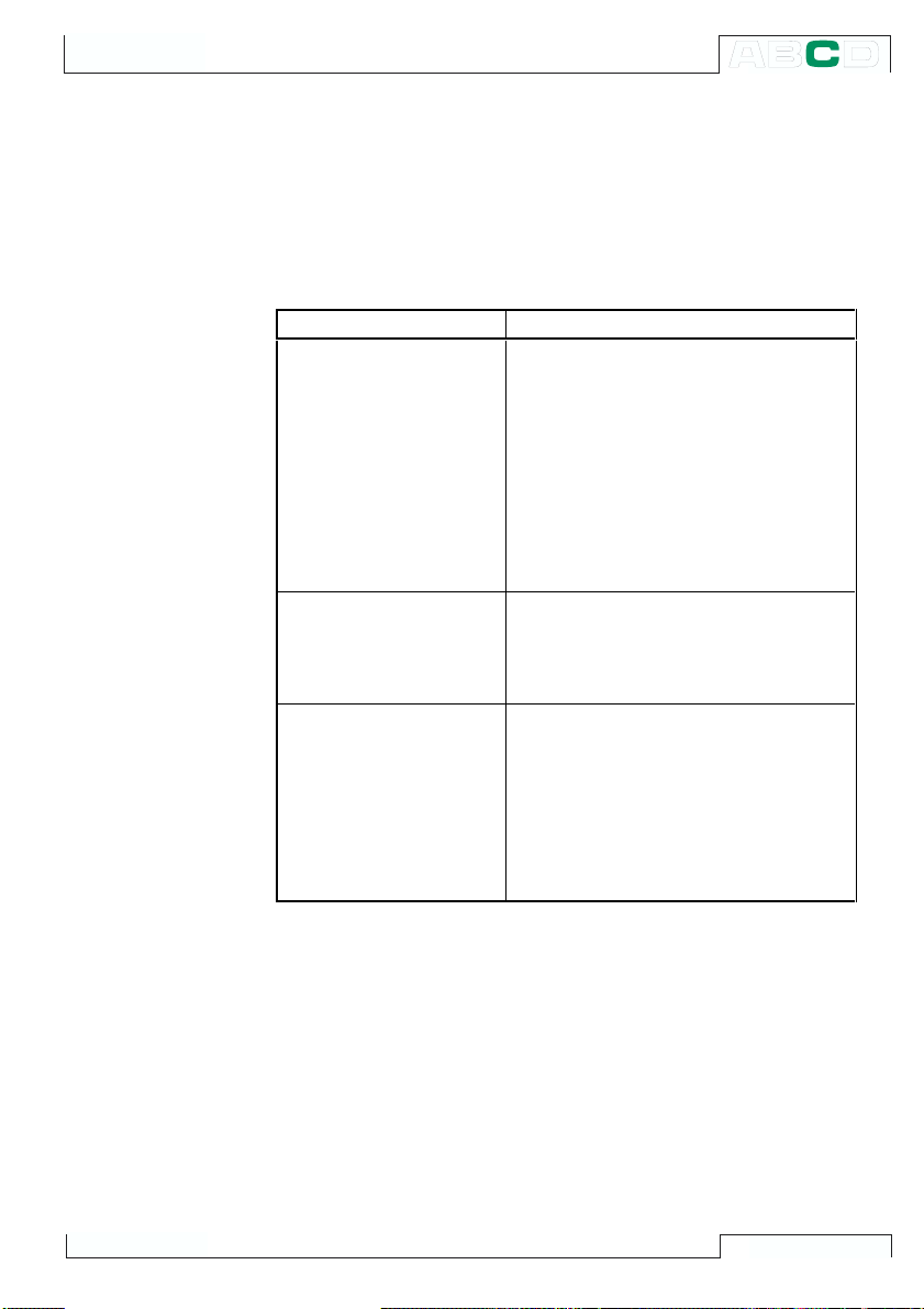
Error situations
Additional Information
The easiest way to avoid errors in thermocouple measurement and
simulation is to check carefully the used wiring and the Reference
Junction mode. The following table describes the typical error situations and possible causes/corrections when working with thermocouples:
PROBLEM CAUSE
MC3 (or the instrument
under test when
simulating
thermovoltages)
measures the
temperature/millivolt
signal, but the displayed
temperature reading is all
wrong.
(The error may vary fro m
0 to about ±50°C
depending on the type of
the error)
MC3 (or the instrument
under test) dis pl ays
random readings during
thermocouple
measurement.
MC3 displays unstable
readings during
thermocouple simulation.
• The thermocouple type selected in
MC3 does not correspond with the
used thermocouple.
• The selected Reference Junction
mode is not in accordance with the
used wiring.
• Extension or compensation cable type
or connections are incorrect.
• The polarity of the cables are
incorrect.
• Incorrect connections.
• The wiring is broken.
• Interference from a mobile phone or a
radio transmitter affects the
measurement.
• The instrument under calibration uses
voltage pulses to detect open sensor.
When MC3 detects these pulses, it
tries to compensate for them, which
causes the unstable output. Prevent
these pulses for the time of
calibration. Refer to the service
manual of the instrument under
calibration on ho w to prevent these
open sensor detecti on pulses.
71
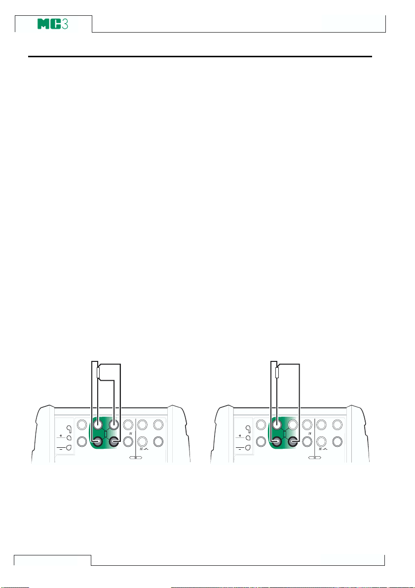
Advanced Operation and Configuration
Resistance and RTD Measurement, Connections
The two main problems in resistance and RTD measurement are
the effects of wiring resistances and thermovoltages in the resistance measurement circuit. If possible, use 4-wire connection to
eliminate the effect of wiring resistance. The special resistance measurement sequence of MC3 eliminates the thermovoltages of the
resistance measurement circuit.
MC3 continuously checks the connection type during resistance
and RTD measurement. The found connection type is displayed on
the resistance or RTD measurement window.
4-wire System
MC3 sources current through the resistor
from the two left side terminals. MC3 measures the voltage drop across the resistor
from the two right side terminals. The 4wire method gives the resistance between
the terminals of the resistor, it is insensitive to the resistance of the connection
wires.
V , 1,
V , ,
O U T P U TM E A S U R E & S IM U L A T E M E A S U R E
E T E
2 - w x m t r
+ 2 4 V
1
m e a s / s i n k
T / C IN T . R J
T / C O R E X T
W I R E S O N L Y
T / C , L o w V
4 - w m e a s
R , R T D
3 & 4 - w m e a s
3-wire System
MC3 sources current through the resistor
from the two left side terminals. MC3 measures the voltage drop across the entire
current loop and across the low side connection wire. If both left side connection
wires are identical, MC3 can compensate
for the resistance of the connection wires.
V , 1,
V , ,
O U T P U TM E A S U R E & S IM U L A T E M E A S U R E
E T E
2 - w x m t r
+ 2 4 V
1
m e a s / s i n k
T / C IN T . R J
T / C O R E X T
W I R E S O N L Y
T / C , L o w V
4 - w m e a s
R , R T D
3 & 4 - w m e a s
72
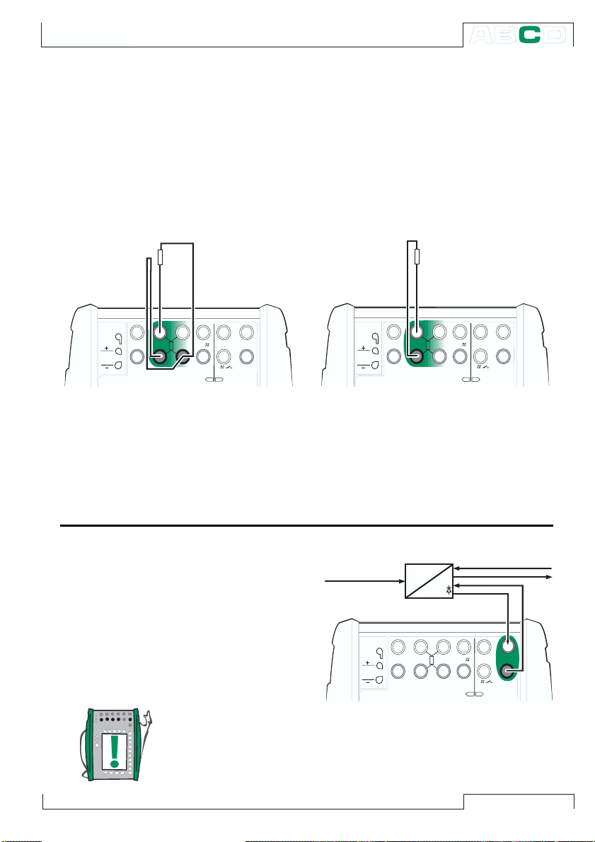
Additional Information
Using a Compensation Loop
MC3 sources current through the resistor
and the compensation loop from the two
left side terminals. MC3 measures the voltage drop across the entire current loop and
across the compensation loop. If the compensation loop and the connection wires
of the resistor are identical, MC3 can compensate for the resistance of the connection wires.
V , 1,
V , ,
O U T P U TM E A S U R E & S IM U L A T E M E A S U R E
E T E
2 - w x m t r
+ 2 4 V
1
m e a s / s i n k
T / C IN T . R J
T / C O R E X T
W I R E S O N L Y
T / C , L o w V
4 - w m e a s
R , R T D
3 & 4 - w m e a s
When the compensation loop wiring system is used, MC3 displays the text 3-wire.
2-wire System
Calibrator sources current through the resistor and measures the voltage drop
across the same terminals.
The result is acceptable, if the resistance
of the connection wires is low.
V , 1,
V , ,
O U T P U TM E A S U R E & S I M U L A T E M E A S U R E
E T E
2 - w x m t r
1
+ 2 4 V
m e a s / s i n k
T / C IN T . R J
T / C O R EX T
W I R E S O N L Y
T / C , L o w V
4 - w m e a s
R , R T D
3 & 4 - w m e a s
Current Measurement Parallel to a Test Diode, Connections
The impedance of MC3s milliampere input
is low enough to enable current measurement
parallel to a test diode in a 20mA circuit.
Connection:
MC3 parallels the test diode of the transmitter and measures the externally supplied
output current of the transmitter.
Note.
In higher temperatures: The leakage of the diode in the instrument
may affect the accuracy.
I n p u t s i g n a l
T / C IN T . R J
T / C O R E X T
W I R E S O N L Y
T / C , L o w V
+
X
I
4 - w m e a s
R , R T D
3 & 4 - w m e a s
V , 1,
V , ,
O U T P U TM E A S U R E & S IM U L A T E M E A S U R E
E T E
+ 2 4 V
2 - w x m t r
2 - w x m t r
1
1
m e a s / s i n k
m e a s / s i n k
73

Advanced Operation and Configuration
E T s e c t i o n
Parallel Functions in MC3
This chapter explains what kind of simultaneous tasks you can do
with MC3.
Every section in MC3
may simultaneously
have their own tasks.
The computer connector may also have its
own independent task.
The ET section has a
double action ability:
When one of the sensor measure & generate section terminals (
used for measuring purposes. Then an electrical output signal may
be generated from the ET sections output terminals. This feature is
not available when generating a signal from the sensor measure &
generate section terminals.
The ET section is also capable of doing the following double tasks:
· Measuring Low Voltages or thermocouples (connected to any
terminal used when measuring thermocouples) and at the same
time either measuring or simulating an RTD with the RTD sensor terminals.
· Generating Low voltages or simulating a thermocouple (connected to any terminal used when simulating thermocouples)
and at the same time measuring with the RTD sensor terminals.
W h e n
m e a s u r i n g
i n t h i s p a r t . . .
E l e c t r i c a l o u t p u t
i s p o s s i b l e i n
t h i s p a r t .
V , 1,
V , ,
O U T P U TM E A S U R E & S IM U L A T E M E A S U R E
E T E
2 - w xm tr
+ 2 4 V
1
m e a s / s i n k
T / C IN T . R J
T / C O R E X T
W IR E S O N L Y
T / C , L o w V
E T s e c t i o n
4 - w m e a s
R , R T D
3 & 4 - w m e a s
T/C INT RJ, T/C Low V, or R,RTD terminals) is
74
Warning!
There is no galvanic isolation between the ET sections mea-
suring terminals and generating terminals.

Calibration
Things discussed in Part D:
· General presentation of what
calibration is and the phases
of a typical calibration procedure.
· A description of a calibration
procedure using MC3.
· Some application examples on
how to perform the calibration
of certain instruments.
· Creating, editing and deleting
Instruments.
· Viewing calibration results.

General
Calibration
MC3 is a stand-alone calibrator as well as a calibrator communicating with calibration software.
MC3 supports stand-alone calibration and off-line calibration.
The following list briefly describes these methods:
· In stand-alone calibration, all instrument and calibration result
data is stored in MC3s memory. No external calibration database is used.
· In off-line calibration (sometimes also called batch calibration),
the instrument data is downloaded from a calibration software.
The calibration is done just as in stand-alone calibration, but
calibration procedures are downloaded from a software and
the saved results are uploaded to the calibration software.
Note that off-line calibration requires the QCAL option. It also requires the computer communication cable to connect MC3 to a PCs
serial port.
76
Note.
MC3 stores one As Found calibration and one As Left calibration
per instrument. Additional As Found or As Left calibrations for the
same instrument overwrite the older results. Use a calibration software to transfer existing calibration results to the calibration
softwares database before performing more calibrations.

Phases of Instrument Calibration
R e a d S t a r t i n g
G u i d e t e x t
A s F o u n d
c a l i b r a t i o n
S a v e A s
F o u n d r e s u l t s
General
S t a r t
A d j u s t m e n t
n o
r e q u i r e d ?
* I f i t i s n o t p o s s i b l e
t o a d j u s t t h e
m a x i m u m e r r o r
b e l o w t h e "
l i m i t , c o n s i d e r
r e p l a c i n g t h e
i n s t r u m e n t w i t h
a m o r e a c c u r a t e o n e .
R e j e c t i f
y e s
R e a d A d j u s t i n g
G u i d e t e x t
A d j u s t m e n t
n o *
"
W i t h i n
l i m i t s ?
y e s
A s L e f t
c a l i b r a t i o n
S a v e A s L e f t
r e s u l t s
R e a d F i n i s h i n g
G u i d e t e x t
E n d
The picture gives a general view of the phases in a calibration
procedure. MC3 supports three separate guide texts (white blocks
in the picture):
One is displayed when starting the calibration.
Another when the adjustment utility is started.
The third text is displayed when ending the calibration.
The guide texts may be entered in MC3 or they may be downloaded
from a PC with a calibration software.
77

Calibration
%
As Found Calibration
The As Found calibration documents the state of the instrument
before carrying out any adjustments. The calibration states the
amount of drift in the instrument during the calibration period.
MC3 does not require you to save an As Found calibration. If you
do not want to save information of the instruments state before
adjustment, just do the adjustments needed and perform the As
Left calibrations.
Adjustment
MC3 calculates (among other figures) the maximum error found
during the calibration. Depending on the value of the maximum error, you decide whether you adjust the instrument or not. MC3 supports four different error limit settings:
Reject if > acceptance limit for found maximum error,
Adjust if > the instrument need to be adjusted if this
Do not adjust if < adjusting the instrument is not
Adjust to < after adjusting, the maximum error should
MC3 has a special adjustment utility tool that can be used when the
input signal of the instrument is generated/simulated with MC3. See
chapter MC3s Support for Instrument Adjustment on page 96.
We recommend you use the utility whenever possible. In all other
situations, use the error graph and its error value to have a view on
how the adjustment affects the accuracy of the instrument and how
close the output signal is from the target value.
Use the instruments ZERO adjustment at lower end of the range.
Adjust the higher end of the range with the instruments SPAN adjustment. The two adjustment points do not necessarily need to be
the end points of the instrument range. You may want to use other
E r r o r
0
0 2 5 5 0 7 5 1 0 0
limit is exceeded,
necessary / of use and
not exceed this limit.
78

N
%
%
General
points to optimize the calibration at the most important part of the
range. Note, however, that if the points are very close to each other ,
the error at other points of the range may be quite big (see As Left
Calibration below).
E r r o r
As Left Calibration
0
Z E R O
0 2 5 5 0 7 5 1 0 0 %
S P A
The As Left calibration documents the state of the instrument after
the possible adjustment.
MC3 does not require you to save an As Left calibration. If the As
Found calibration proves to be good and no adjustment is needed,
you may omit the As Left calibration.
E r r o r
0
0 2 5 5 0 7 5 1 0 0
E r r o r
0
0 2 5 5 0 7 5 1 0 0
The pictures above display different As Left calibration graphs after
two different kinds of adjustments.
In the leftmost picture, the error is minimized at the end points of the
instrument range. This results in a relatively notable error in the
middle of the span. If the middle of the span is the area, where the
measurement is usually situated, then this method is not recommended.
The rightmost picture displays the error graph when the maximum
error is minimized by ìlowering the graphî. As a result, the error
minimum is at approx. 30†% and 70†% of the span.
Note that these adjustment strategies are just examples. There is
an unlimited amount of ìcorrectî ways to adjust an instrument.
79

Calibration
Required Sections for Different Input/Output Signal Combinations
Consider the type of your instrument before doing a calibration:
· What are the input and output quantities/ports?
· Is the input signal measured, generated/simulated or keyed
(Input method)?
· Is the output signal measured or keyed (Output method)?
Use the following tables find out the required sections for each supported input/output quantity and method:
Table for choosing the input section Table for choosing the output section
QUANTITY METHOD REQ. SECTION QUANTITY METHOD REQ. SECTION
Voltage
Low Volta g e
Current
Resistance
Pressure
Temperatur e
TC temperatu re
RTD tempe r at u r e
Frequency
Value
Measured
Generated
Keyed none
ET measured
Generated
Keyed none(* Keyed none
Measured
E generated
ET generated
Keyed none Keyed none(**
Measured
Simulated
Keyed none(* Keyednone
Measured
Keyed none(** Keyed none(*
Keyed none
Measured
Simulated
Measured
Simulated
Measured
Generated
Keyed none
E Voltage
ET
Low Voltage
ET
ET Current
E Resistance
E
ET Pressure
ET Temp.
ET TC temperature
Press. RTD temperature
Frequency
ET
ET Value
ET Switch
ET
E
ET
Measured
Keyed none
ET Measured
Keyed none
Measured
Measured
Keyed none(*
Measured
Keyed none
Measured
Measured
Measured
Keyed none
Keyed none
Measured
E
ET
E
ET
Press.
ET
ET
E
E
(
*
(
*
80
*)Input or Output Method Keyed is available as an option only if the ET
section is installed (models MC3MF and MC5TE).
**) Input or Output Method Keyed is available as an option only if a pres-
sure input is installed into the pressure section (models MC3MF and
MC5PE).

General
The general principle is: The same section may not be used for
both the input and the output signal. There are however some exceptions to that rule:
If when checking the required sections both the input and the output section is ET, but the cells are grayed, check the table below. It
presents all supported combinations where both the input signal
and the output signal is connected to the ET section.
Supported input/output quantities and methods where both the
input signal and the output signal is connected to the ET section:
INPUT QUANTITY INPUT M ETHOD OUTPUT QUANTITY OUTP UT M E THO D
Voltage
Low Voltage
Current
TC temperature
RTD temperature
Frequency
Generated
Generated
Generated
ET Measured
ET Generated
ET Generated
ET Generated
Measured
Simulated
Measured
Simulated
Generated
Generated
Generated
Generated
Low Voltage
TC Temperature
RTD Temperature
RTD Temperature
Low Voltage
TC Temperature
RTD Temperature
RTD Temperature
RTD Temperature
TC Temperature
TC Temperature
Low Voltage
TC Temperature
RTD Temperature
Resistance
ET Measured
Measured
Measured
Measured
ET Measured
Measured
Measured
Measured
Measured
Measured
Measured
ET Measured
Measured
Measured
Measured
Each row is a supported combination.
A reminder. Available sections in different MC3 models:
MC3 model Available sections
MF
MC3
MC5
MC5
TE
PE
Electrical (E), Temperature (ET) and Pressure sections
Electrical (E) and Temperature (ET) sections
Electrical (E) and Pressure sections
81

Calibration
Calibrating an Instrument
Selecting the Instrument to Be Calibrated
To move from Basic Mode to Calibration Mode, press the A /
CalibrationMode Function Key. A
list of instruments available in
MC3s memory is presented. If you
do not have any instrument data in
MC3s memory, either download
them from a calibration software or
create instruments in MC3 as described in chapter Adding New In-
struments on page 97. The Position ID / Device ID of an already
calibrated instrument is tick-marked
( )
When you move the cursor (the inverted text), the additional data presented in the lower part of the
screen changes to reflect the data of the current instrument.
Select one of the available instruments by pressing the
C/Select key.
3 0 . 0 1 . 2 0 0 1 1 3 : 5 0
P O S I T I O N / D E V I C E I D
1 0 1 - X I - 0 0 1 . 1
1 1 2 - T T - 0 0 3 . 1
1 1 2 - T T - 0 0 7 . 1
P T 1 0 1 . 6
P T 1 1 2 . 1 2
P T 1 1 5 . 1 5 - 1
P T 1 1 5 . 1 5 - 2
P T 1 1 2 . 1 6
T T 1 1 2 . 0 8
T T 1 1 2 . 1 0
T T 1 1 2 . 1 2
D e v i c e I D
T T 1 1 2 . 0 7
P o s i t i o n N a m e
I n t a k e T e m p e r a t u r e o n F e e d 1
C a l i b r a t e d
N o t C a l i b r a t e d
B a s i c
M o d e
S e l e c t
M E N U
or the
82
Note.
If there are a lot instrument data in MC3s memory, displaying the
list may take a few seconds.

The Instrument Window
The Instrument window gives you
an overview of the selected instrument. You can view detailed instrument data by pressing the D/MENU
Function Key and 1/View Instru-
ment Details. To edit the Instru-
ment data, press the B/Edit Function Key. More information on editing instrument data is in chapter
Editing Instrument Data on page
98.
To calibrate the selected instru-
ment, simply press
General calibration procedures are
discussed in chapter A Calibration
Procedure Using MC3 on page 84. Some calibration examples
are available starting from chapter Examples of Instrument Cali-
bration on page 87.
If a Starting Guide text is written, it appears before the Calibration
Windows are opened. To close the window displaying the note text,
press D/OK.
Calibrating an Instrument
1 1 2 - T T - 0 0 3 . 1
I n t a k e T e m p e r a t u r e o n F e e d 1
T r a n s f e r F u n c t i o n
C a l . P o i n t s
I N P U T
M e t h o d
S e n s o r T y p e
O U T P U T
M e t h o d
C/Calibrate.
B a c k
3 0 . 0 1 . 2 0 0 1 1 3 : 5 1
I N S T R U M E N T
L i n e a r
5
0 . 0 0 . . . 1 0 0 . 0 0 ° C
S i m u l a t e d
P t 1 0 0 a3 8 5
4 . 0 0 0 0 . . . 2 0 . 0 0 0 0 m A
M e a s u r e d
E d i t C a l i b r a t e M E N U
¯
83
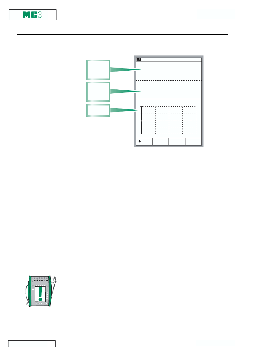
Calibration
A Calibration Procedure Using MC3
The Calibration Windows:
I n p u t
S i g n a l
W i n d o w
O u t p u t
S i g n a l
W i n d o w
E r r o r
G r a p h
A typical calibration procedure using MC3 is as follows:
We assume you have already selected the instrument to be
calibrated and are viewing/editing the selected instruments data
pages. See Selecting the Instrument to Be Calibrated on page
82 for information on how to enter Calibration Mode and selecting instruments for calibration.
1. Make the required connections and test them by altering the
input signal in with the Instrument Adjustment utility (if you
havent done the connections and testing in Basic Mode).
2. Start the calibration run by pressing
passes through all calibration points depends on the Calibra-
tion Method setting:
In Automatic calibration MC3 generates/simulates the input
signal. See chapters
About Automatic Calibration on page 86 and
About Manual Calibration on page 86.
3 0 . 0 1 . 2 0 0 1 1 3 : 5 2
I n p u t
R T D T e m p e r a t u r e [ E T : S i m u l ]
O u t p u t
C u r r e n t [ E : M e a s ]
3 . 9 7 6 2
E r r o r
1 . 0 0
+
0
0 % 5 0 % 1 0 0 %
B a c k
S t a r t M E N U
0 . 0 0
P t 1 0 0 a3 8 5
° C ( I T S 9 0 )
m A
- 0 . 1 5 % o f s p a n
A d j u s t
B/Start. The way MC3
84
Note.
You can pause a calibration run whenever you want by pressing the A/Stop Function Key. Then you are provided with the
following (self-explanatory) choices:
A/Continue
B/End
C/Skip Point.
3. When the calibration run is ready, you can either Reject the
results (
A/RejectCalibration) or Continue by pressing the
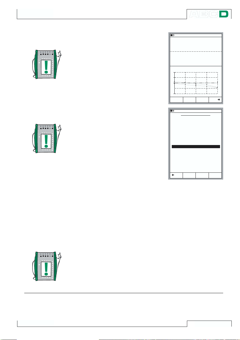
Calibrating an Instrument
D/Saveè Function Key.
Note.
If the maximum error of the calibra-
tion results exceed the Adjustif>
error limit, a message window with
the following text: The calibrated
instrument need to be adjusted.
4. Enter the environmental data and
save the results using one of the
options provided in the Function
B to D.
Keys
Notes.
Some of the temperature data may
be pre-entered by MC3, provided
the data is available for MC3 (pressure input, the E section or the ET
section was used during the calibration).
3 0 . 0 1 . 2 0 0 1 1 3 : 5 7
I n p u t
R T D T e m p e r a t u r e [ E T : S i m u l ]
O u t p u t
C u r r e n t [ E : M e a s ]
4 . 0 2 9 3
E r r o r
1 . 0 0
+
0
0 % 5 0 % 1 0 0 %
R e j e c t
C a l i b r a t i o n
3 0 . 0 1 . 2 0 0 1 1 3 : 5 8
E N V I R O N M E N T A L D A T A
D e v i c e T e m p e r a t u r e
E n v i r o n m e n t T e m p .
I n p u t M o d u l e T e m p .
O u t p u t M o d u l e T e m p .
H u m i d i t y
C a l i b r a t e d b y :
A n d y H a n d y m a n
N o t e s :
J u s t T e s t i n g
0 . 0 0
P t 1 0 0 a3 8 5
° C ( I T S 9 0 )
m A
0 . 1 8 % o f s p a n
2 1 . 0
2 1 . 0
3 1 . 6
2 9 . 6
3 0
S a v e
° C
° C
° C
° C
%
MC3 stores one As Found calibration and one As Left calibra-
S a v e
S a v e
tion per instrument. Additional
As Found or As Left calibrations
B a c k
A s F o u n d
A s L e f t
S a v e
A s B o t h
for the same instrument overwrite the older results. Use a
calibration software to transfer existing calibration results
to the calibration softwares database before performing
more calibrations.
5. Continue either with another calibration run or end the calibration procedure. In the latter case you will see the possible
ishing Guide text before you are back viewing the Instrument
Fin-
Data.
Note.
If you are calibrating instruments using off-line method then please
keep in mind this: When you upload the results from MC3 to the
calibration software, the results are by default also left in MC3s
memory. To free memory in MC3 by deleting the results, see Delet-
ing Instruments on page 101.
See also:
MC3s Support for Instrument Adjustment on page 96.
Viewing Calibration Results on page 102.
85

Calibration
About Automatic Calibration
Automatic calibration is possible when MC3 is able to generate/
simulate the input signal.
Automatic calibration is selected in the
on the Instrument Data pages. More information on editing instrument data is in chapter Editing Instrument Data on page 98.
In Automatic calibration MC3 generates/simulates the input signal. When the input signal is within the
bration Point Deviation limits, MC3 waits for the output signal to
stabilize (the Setpoint Delay setting). Then the calibration point is
accepted automatically and MC3 continues with the next calibration point.
If the input signal never stabilizes (the symbol is visible continuously), but you want MC3 to save the results anyhow, press the
B/Force Accept Function Key.
About Manual Calibration
In manual calibration, you will have to manually set the input signal
to a level that the next calibration point requires. Manual calibration
is possible in almost all situations. Even for calibrations that could
be done automatically.
If the input signal is measured, the input signal window displays a
Desired Input Value X.xxxx text to help you remember what is
the next target value.
If the input signal is generated/simulated, MC3 automatically
changes the input signal to the next target value, but does not continue until you manually accept the point.
Use the
and continue to the next point until all points are accepted.
Note.
If the calibration points are defined for the output signal, set the
input signal to such a level that the instrument to be calibrated creates the required output signal.
B/AcceptReadings Function Key to save the point data
Calibration Method field
Maximum Allowed Cali-
86

Calibrating an Instrument
Examples of Instrument Calibration
This User Guide has only a few examples of how to calibrate an
instrument. Many calibration procedures not presented here are
either very similar to the ones presented in the following chapters
or they can be combined, e.g. the calibration of a Pressure Indi-
cator/Recorder is partly done as a Pressure Transmitter and partly
as a Temperature Indicator/Recorder calibration.
Use the information presented in Part B of this manual when connecting/calibrating instruments that do not have a separate calibration procedure presented in this part.
The calibration of the following instruments are presented in this
manual:
Pressure Transmitters on page 88,
Temperature Sensors on page 90,
Temperature Indicators and Recorders on page 92 and
Electrical Limit Switches on page 94.
87
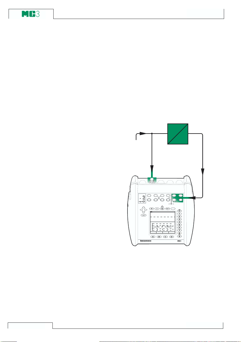
Calibration
Pressure Transmitters
This procedure suits all instruments with a pressure input and any
kind of electrical output signal. Both the input and output signal
range should be measurable with MC3. Pressure transmitter calibration can be done with models MC3MF and MC3PE.
Required sections
· A pressure input (PRxxx).
· The E section for measuring the electrical output signal.
Preparations
1. Connect the input signal of the instrument to the pressure input.
2. Connect the pressure source both to the
instruments input and to the pressure
input.
3. Connect the instruments output signal
to the chosen electrical input port in
MC3.
4. Test the connections in Basic Mode if
needed. To quickly configure the Basic
Modes windows, go to Calibration
Mode, select the instrument to be calibrated and the Function Key
brate but immediately return to Basic
Mode.
C/Cali-
P r e s s u r e
S o u r c e
T /C IN T . R J
T /C , Lo w V
T/ C OR EX T
W IRE S O N LY
In p ut
D es i re d In p ut V a lu e 0. 5 00 0
O u tp ut
E rr or
1 .00
+
0
0 % 5 0 % 1 00 %
P au s e
M U L T I F U N C T I O N
R , R T D
0 6.1 0 .2 00 0 1 1: 49
P re s su r e [P 1: I NT 6 C ]
0 . 4 9 8 2
C u rr en t [E : M ea s ]
8 . 0 3 1 0
A cc e pt
R ea d in gs
3 & 4- w m e as
4 -w me as
0 .2 8 % o f sp a n
P
2 -w xm tr
+ 24 V
V , 1,
V , ,
OU T PU TM EA SU RE & S IM UL AT E M EA SU RE
ET E
G a ug e
b ar
m A
C A L I B R A T O R
E
1
m ea s/ sin k
88

Calibrating an Instrument
Calibration
1. Move to Calibration Mode, select the
instrument to be calibrated and start the
calibration as presented in chapter A
Calibration Procedure Using MC3 on
page 84.
2. Set the pressure using, e.g. a pressure
pump.
3. Accept the points using the
Readings Function Key.
B/Accept
Warning!
Working with pressure instruments can be hazardous. Only
qualified personnel may use pressure instruments and pressure sources.
4. Save or reject the results as is de-
scribed in chapter A Calibration Pro-
cedure Using MC3 on page 84.
5. Do the possible adjustment and the As
Found calibration or return to the Instrument window.
Next
MC3s Support for Instrument Adjustment on page 96
89

Calibration
Temperature Sensors
This procedure suits temperature sensors no matter if they are RTDs
or thermocouples. The sensors output signal is measured with MC3
or it is keyed into MC3. The reference temperature is either measured with MC3 or entered to MC3. Temperature sensor calibration
can be done with models MC3MF and MC3TE.
If you measure the reference temperature using MC3, remember
the following conditions:
· If the sensor to be calibrated is a thermocouple, the reference
thermometer needs to be an RTD sensor.
· If the sensor to be calibrated is an RTD sensor, the reference
thermometer needs to be a thermocouple.
Required section
· The ET section for measuring the sensors output signal and
possibly also for measuring the reference temperature.
Preparations
1. Place the sensor of the instrument (and
the sensor of the reference thermometer) into the calibration bath/dry block.
Connect it/them to suitable terminals in
MC3 (RTD or T/C). If the sensor is a
thermocouple, select one of the available reference junction methods:
· The internal Reference Junction
is in use.
· The reference junction is fixed to
0°C.
· The reference junction temperature is entered.
· The reference junction temperature is measured externally using
an RTD connected to the RTD terminals.
See Part C for additional information
concerning the reference junction methods.
2. Test the connections in Basic Mode if
needed. To quickly configure the Basic
Modes windows, go to Calibration
Mode, select the instrument to be calibrated and the Function Key C/Cali-
brate but immediately return to Basic
Mode.
R e f e r e n c e
T / C IN T . R J
t h e r m o m e t e r
4 -w m e as
T / C , L o w V
R , R T D
3 & 4 -w m e as
0 6 .1 0 . 2 0 0 0 1 1 : 0 6
In p u t
T C T e m p e r a t u r e [ E T : C o n t r o l]
2 5 . 0 1
D e s i r e d I n p u t V a l u e 2 5 .0 0
O u tp u t
R T D T e m p e r a t u r e [ E T : M e a s ]
2 4 . 9 4
E r ro r
1 .0 0
+
0
0 % 5 0 % 1 0 0 %
A c c e p t
P a u s e
R e a d i n g s
V , 1,
O U T P U TM E A S U R E & S I M U L A TE M E A S U R E
K N i C r /N i A l
° C (I T S 9 0 )
P t 1 0 0
° C (I T S 9 0 )
- 0 .0 6 % o f s p a n
2 -w xm tr
+ 2 4 V
1
m e a s/ s in k
V , ,
E T E
a
3 8 5
S e n s o r
T / C O R E X T
W I RE S O N L Y
90
M U L T I F U N C T I O N C A L I B R A T O R

Calibrating an Instrument
Calibration
1. Move to Calibration Mode, select the
instrument to be calibrated and start the
calibration as presented in chapter A
Calibration Procedure Using MC3 on
page 84.
2. Start the calibration as presented in
chapter A Calibration Procedure Us-
ing MC3 on page 84.
3. Set the temperature of the bath/dry
block to the required calibration point.
Wait until the temperature stabilizes.
Hint!
With small changes, this procedure should also suit all tempera-
ture instruments with a fixed sensor. In that case, use a reference
sensor that can be connected to MC3 to measure the input signal
and either measure or enter the output signal of the instrument.
Use one of the following examples for the output signal:
· Temperature Transmitter with sensor. See the example
Pressure Transmitters on page 88.
· Temperature Indicators/Recorders with sensor. See the
example Temperature Indicators and Recorders on page
92.
· Temperature switches (thermostats) with sensor. See the
example Electrical Limit Switches on page 94.
4. If the reading of the reference temperature sensor is entered manually, enter
the value and press B/Accept Read-
ings Function Key. If the reference tem-
perature sensor is connected to MC3,
accept the readings using the B/Accept
Readings Function Key.
5. Save or reject the results as is described in chapter A Calibration Pro-
cedure Using MC3 on page 84.
6. Do the possible adjustment and the As
Found calibration or return to the Instrument window.
Next
MC3s Support for Instrument Adjustment on page 96
91

Calibration
Temperature Indicators and Recorders
This procedure suits Temperature Indicators/Recorders no matter
if the sensor is an RTD or a thermocouple. The instruments input
signal is simulated using MC3 and the output reading is entered
into MC3. Temperature indicator and recorder calibration can be
done with models MC3MF and MC3TE.
Required section
· The ET section for simulating the temperature sensor.
Preparations
1. Connect suitable terminals in MC3 to
the input connectors of the indicator/
recorder.
2. If the sensor to be simulated is a thermocouple, select one of the following
reference junction methods:
· The internal Reference Junction
is in use.
· The reference junction is fixed to
0°C.
· The reference junction temperature is entered.
· The reference junction temperature is measured externally using
an RTD connected to the RTD terminals.
See Part C for additional information
concerning the reference junction methods.
3. If the sensor to be simulated is an RTD,
the used wiring system depends on the
instrument to be calibrated. Remember
to only use the two leftmost RTD terminals in MC3.
4. Test the connections in Basic Mode if
needed. To quickly configure the Basic
Modes windows, go to Calibration
Mode, select the instrument to be calibrated and the Function Key
brate but immediately return to Basic
C/Cali-
Mode.
3 & 4 -w m e a s
4 -w m e as
P t 1 0 0 a3 8 5
° C (I T S 9 0 )
° C
- 0 .2 0 % o f s p a n
V , 1 ,
O U T PU TM E A S U R E & S IM U L A TE M E A S UR E
E T E
2 -w xm t r
+ 2 4 V
1
m e a s/ s in k
V , ,
T / C IN T . R J
T / C , L o w V
R , R T D
T /C O R E X T
W I RE S O N L Y
0 6 .1 0 . 2 00 0 1 0 : 4 6
In p u t
R T D T e m p e r a tu r e [ E T : S i m u l .]
7 5 . 0 0
O u t p u t
V a l u e [ K e y e d ]
7 4 . 8 0 0
E n t e r O u t p u t R e a d i n g
E r ro r
1 .0 0
+
0
0 % 5 0 % 1 0 0 %
A c c e p t
P a u s e
R e a d in g s
M U L T I F U N C T I O N C A L I B R A T O R
92

Calibrating an Instrument
Calibration
1. Move to Calibration Mode, select the
instrument to be calibrated and start the
calibration as presented in chapter A
Calibration Procedure Using MC3 on
page 84.
2. MC3 simulates the output signal of the
temperature sensor for each calibration
point. The middlemost window displays
the default value for the reading. You
have two possibilities on how to continue:
· Adjust the simulated signal until
the reading of the indicator/recorder is exactly the same as the
default value displayed in MC3.
This method is useful when calibrating analog indicators/recorders and the input signal supports
fine adjustment.
· Select the field displaying the default value and enter the actual
reading. This method is useful
when calibrating indicators with
digital display or when the input
signal cannot be fine adjusted.
3. Accept the points using the
Readings Function Key.
B/Accept
4. Save or reject the results as is de-
scribed in chapter A Calibration Pro-
cedure Using MC3 on page 84.
5. Do the possible adjustment and the As
Found calibration or return to the Instrument window.
Next
Hint!
This procedure can be used as a reference when calibrating any
kind of indicators/recorders. Adapt the input signal connections/
settings according to the instruments input signal.
When calibrating a temperature instrument with a detachable sensor (the input signal is simulated with MC3), use this example as
the source for the input signal part.
MC3s Support for Instrument Adjustment on page 96
93
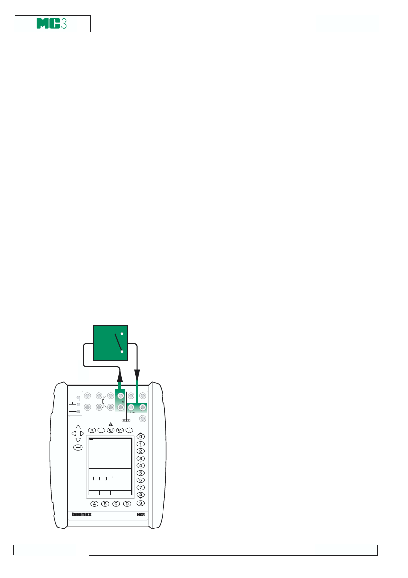
Calibration
Electrical Limit Switches
This procedure suits limit switches with an electrical input. The input signal is generated with MC3. Electrical limit switch calibration
can be done with models MC3MF and MC3TE.
Required sections
· The ET section for generating the required electrical signal
(Voltage or Current).
· The E section for detecting the switchs state.
Preparations
1. Connect the ET sections terminals
marked
OUTPUT to the input of the
switch.
2. Connect the switch contact to the switch
terminals in the E section.
3. Test the connections in Basic Mode if
needed. To quickly configure the Basic
Modes windows, go to Calibration
Mode, select the instrument to be calibrated and the Function Key
brate but immediately return to Basic
C/Cali-
Mode.
T / C IN T . R J
T /C OR EX T
W I RE S O N L Y
T / C , L o w V
In p u t
T e s t in g s w i t c h li m i ts ( 4 /5 )
O u t p u t
P a u s e
R , R T D
?
0 6 .1 0 . 2 00 0 1 0 : 2 9
V o l ta g e [E T : G e n . ]
S w i tc h [E : M e a s . ]
8 . 0 3 1 0
5 . 0 2 3
- - - - - - -
4 -w m e as
3 & 4 -w m e as
V
A c t u a t e
D e a c t u a t e
V , 1,
O U T P U TS E N S O R M E A S U R E & S I M U L A TE
E T E
M a x in p u t:
6 0 V D C / 3 0 V A C
7 .0 0 0
5 .5 0 0
4 .5 0 0
3 .0 0 0
2 -w xm t r
+ 2 4 V
1
m e a s/ s in k
V , ,
®
H A R T
M E A S U R E
L o w V
Calibration
1. Move to Calibration Mode and select the
instrument to be calibrated.
2. Start the calibration as is presented in
chapter A Calibration Procedure Us-
ing MC3 on page 84. MC3 does the
Prescan if it is enabled. During the
prescan, MC3 searches for approximate values for the actuating and
deactuating point. This speeds up the
final test without sacrificing accuracy.
The prescan test is done only once in a
calibration.
· By default, the
Prescan is set to on.
If you do not want MC3 to perform a
prescan, disable it (commands
D/MENU and 2/Prescan). When
Prescan is set to of f, MC3 uses the
whole scan range also during the
actual test.
3. The actual test is done automatically:
MC3 slowly increases the input signal
until the switch actuates and continues
by decreasing the input signal until the
switch deactuates. MC3s screen displays the obtained data as the test advances.
94
M U L T I F U N C T I O N
C A L I B R A T O R
 Loading...