

Page 1

FBXXX___tgeng0000
Field Temperature Block series
Beamex® FB150, FB350, FB660
User Guide
Page 2

FBXXX Field Temperature Block
ii
Page 3

iii
Table of Contents
1 Before You Start .......................................................................1
1.1 Introduction ............................................................................................... 1
1.2 Unpacking ................................................................................................ 2
1.3 Symbols Used ........................................................................................... 3
1.4 Safety Information ..................................................................................... 4
1.4.1 Warnings .........................................................................................................4
1.4.2 Cautions ..........................................................................................................6
1.5 CE Comments ........................................................................................... 7
1.5.1 EMC Directive .................................................................................................7
1.5.2 Immunity Testing .............................................................................................8
1.5.3 Emission Testing ..............................................................................................8
1.5.4 Low Voltage Directive (Safety) ........................................................................8
1.6 Authorized Service Centers ...................................................................... 9
2 Specications and Environmental Conditions .................... 11
2.1 Specifications ......................................................................................... 11
2.2 Environmental Conditions ....................................................................... 12
3 Quick Start .............................................................................. 13
3.1 Setup ....................................................................................................... 13
3.2 Parts and Controls .................................................................................. 14
3.2.1 Display Panel ................................................................................................15
3.2.2 Display ..........................................................................................................16
3.2.3 Power Panel ..................................................................................................17
3.2.4 -R Option Panel (-R models only) ..................................................................20
3.3 Languages .............................................................................................. 21
3.3.1 Language Selection ......................................................................................22
3.3.2 Reset to English Language ...........................................................................22
4 Menu Structure .......................................................................23
4.1 Temp Setup Menu ................................................................................... 23
4.2 Prog Menu .............................................................................................. 24
4.3 System Menu .......................................................................................... 25
4.4 Input Setup (-R only) ............................................................................... 26
5 Controller operation...............................................................27
Page 4

FBXXX Field Temperature Block
iv
5.1 Main Screen ............................................................................................ 27
5.2 Main Menu .............................................................................................. 28
5.2.1 Temp Setup ................................................................................................... 28
5.2.2 Prog Menu .....................................................................................................30
5.2.3 System Menu .................................................................................................32
5.2.4 INPUT SETUP (-R model only) ......................................................................38
6 Digital communication interface...........................................43
6.1 Wiring ...................................................................................................... 43
6.1.1 Setup .............................................................................................................43
6.1.2 Serial Operation ............................................................................................43
6.2 Command Syntax ................................................................................... 44
6.3 Commands by Function or Group .......................................................... 45
6.4 Serial Commands - Alphabetic Listing ................................................... 48
6.5 Non-SCPI Process Commands ............................................................... 66
6.6 Non-SCPI Commands by Function or Group ......................................... 66
7 Troubleshooting .....................................................................69
8 Maintenance ...........................................................................71
8.1 Field Temperature Block Performance Analysis ..................................... 71
Page 5

v
Tables
Table 1 Symbols used ........................................................................................ 3
Table 2 Base Unit Specifications ..................................................................... 11
Table 3 -R Option Specifications .................................................................... 12
Table 4 Matching Certificate Values to ITS-90 Coefficients ............................. 39
Table 5 Setting Coefficients Rtpw, a8, b8, and b4 ........................................... 39
Table 6 Commands by Function or Group ....................................................... 45
Table 7 PROG:SEQ:PAR parameters ............................................................... 55
Table 8 Troubleshooting, problems, causes and solutions .............................. 69
Page 6

FBXXX Field Temperature Block
vi
Figures
Figure 1 Clamp-on ferrite installation ................................................................ 8
Figure 2 FBXXX Field Temperature Block ........................................................ 14
Figure 3 Display panel and keys ..................................................................... 16
Figure 4 FBXXX display ................................................................................... 17
Figure 5 FB150 power panel ........................................................................... 19
Figure 6 FB350 and FB660 power panel ......................................................... 19
Figure 7 -R option panel ................................................................................. 20
Figure 8 Probe connector wiring ..................................................................... 21
Figure 9 Steps to language selection .............................................................. 22
Figure 10 Main Menu - Temp SetUp ................................................................ 23
Figure 11 Main Menu - Prog Menu .................................................................. 24
Figure 12 Main Menu - System Menu .............................................................. 25
Figure 13 Main Menu - Input Setup ................................................................ 26
Figure 14 RS-232 wiring .................................................................................. 44
Page 7

1
Before You Start
Introduction
1 Before You Start
1.1 Introduction
Field Temperature Blocks (FB150, FB350, and FB660) are designed to be reliable,
stable heat sources that can be used in the eld or laboratory. They offer accuracy,
portability, and speed for nearly every eld calibration application. The instruments
have been designed with the eld user in mind and are easy to use while maintaining
stability, uniformity, and accuracy comparable to some laboratory instruments.
Special built-in features make Field Temperature Blocks extremely adaptable. The
exclusive Voltage Compensation allows the technician to plug into mains power with
voltage from 90 V ac to 250 V ac without degradation to the instrument. The Ambient
Temperature Compensation provides the largest operating range in the industry (0°C
to 50°C) with the largest guaranteed temperature range (13°C to 33°C). The Gradient Temperature Compensation keeps the axial gradient within specication over the
entire temperature range of the instrument and over the specied guaranteed operating temperature range. These combined features along with the rugged design, light
weight, and small size make this line of instruments ideal for eld applications.
Unique Patent Pending safety features make these the safest eld heat sources available. The unique Air Flow Design keeps the probe handle cool protecting delicate
instruments and the user. The Block Temperature Indicator shows the user when the
well temperature is above 50°C letting the user know when it is safe to remove the
insert or move the instrument. The indicator light illuminates when the instrument is
energized and the well is above 50°C. If the instrument is removed from mains power,
the indicator light ashes until the well has cooled to less than 50°C.
The optional “-R” version (“FBXXX-R”) combines the heat source with a built-in
reference.
The Field Temperature Blocks’ controller uses a PRT sensor and thermoelectric modules or heaters to achieve stable, uniform temperatures throughout the block.
The LCD display continuously shows many useful operating parameters including the
block temperature, the current set-point, block stability, and heating and cooling status.
For the -R version, the reference temperature readings are displayed. The display can
be set to show the information in one of eight different languages; English, Japanese,
Chinese, German, Spanish, French, Russian, and Italian.
The instrument’s rugged design and special features make them ideal for the eld or
the laboratory. With proper use, the instrument provides continued accurate calibration
of temperature sensors and devices. Before use, the user should be familiar with the
warnings, cautions, and operating procedures of the block as described in the User’s
Guide.
Page 8

FBXXX Field Temperature Blocks
Unpacking
2
1.2 Unpacking
Unpack the instrument carefully and inspect it for any damage that may have occurred
during shipment. If there is shipping damage, notify the carrier immediately.
Verify that the following components are present:
FB150
FB150 Field Temperature Block
Insert: FB150-MH2, FB150-MH1, or FB150-B
Power Cord
RS-232 Cable
User Guide
Calibration Certicate and calibration label
LEMO Connector (-R model only)
Well Insulator
Clamp-on ferrites (3) [-R model only]
Tongs (insert removal tool)
FB350
FB350 Field Temperature Block
Insert: FB350-MH2, FB350-MH1, or FB350-B
Power Cord
RS-232 Cable
User Guide
Calibration Certicate and calibration label
LEMO Connector (-R model only)
Clamp-on ferrites (3) (-R model only)
Tongs (insert removal tool)
FB660
FB660 Field Temperature Block
Insert: FB660-MH2, FB660-MH1, or FB660-B
Power Cord
RS-232 Cable
User Guide
Calibration Certicate and calibration label
LEMO Connector (-R model only)
Clamp-on ferrites (3) [-R model only]
Tongs (insert removal tool)
Page 9
3
Before You Start
Symbols Used
If all items are not present, contact an Authorized Service Center (see Section 1.6Authorized Service Centers on page 9).
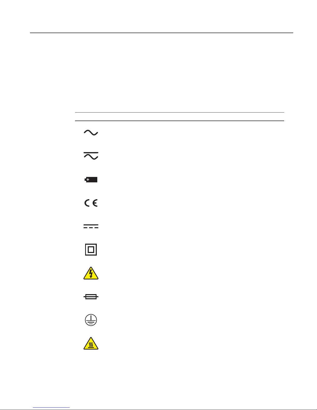
1.3 Symbols Used
Table 1 lists the International Electrical Symbols. Some or all of these symbols may be
used on the instrument or in this guide.
Table 1 Symbols used
Symbol Description
AC (Alternating Current)
AC-DC
Battery
Complies with European Union directives
DC
Double Insulated
Electric Shock
Fuse
PE Ground
Hot Surface (Burn Hazard)
Page 10

FBXXX Field Temperature Blocks
Safety Information
4
Symbol Description
Read the User’s Guide (Important Information)
Off
On
Canadian Standards Association
C-TICK Australian EMC mark
The European Waste Electrical and Electronic Equipment (WEEE) Directive (2002/96/
EC) mark.
1.4 Safety Information
Field Temperature Blocks are designed in accordance with IEC 61010-1, IEC 610102-010 and CAN/CSA 22.2 No 61010.1-04. Use this instrument only as specied in this
manual. Otherwise, the protection provided by the instrument may be impaired. Refer
to the safety information in the Warnings and Cautions sections below.
The following denitions apply to the terms “Warning” and “Caution”.
“Warning” identies conditions and actions that may pose hazards to the user.
“Caution” identies conditions and actions that may damage the instrument
being used.
1.4.1 Warnings
To avoid personal injury, follow these guidelines.
GENERAL
DO NOT use this instrument in environments other than those listed in the User’s
Guide.
Inspect the instrument for damage before each use. Inspect the case. Look for cracks
or missing plastic. DO NOT use the instrument if it appears damaged or operates
abnormally.
Page 11

5
Before You Start
Safety Information
Follow all safety guidelines listed in the User’s Guide.
Calibration equipment should only be used by trained personnel.
If this equipment is used in a manner not specied by the manufacturer, the protection
provided by the equipment may be impaired.
Before initial use, or after transport, or after storage in humid or semi-humid environments, or anytime the instrument has not been energized for more than 10 days, the
instrument needs to be energized for a “dry-out” period of 2 hours before it can be
assumed to meet all of the safety requirements of the IEC 1010-2. If the product is wet
or has been in a wet environment, take necessary measures to remove moisture prior
to applying power such as storage in a low humidity temperature chamber operating at
50°C for 4 hours or more.
DO NOT use this instrument for any application other than calibration work. The
instrument was designed for temperature calibration. Any other use of the instrument
may cause unknown hazards to the user.
DO NOT place the instrument under a cabinet or other structure. Overhead clearance
is required. Always leave enough clearance to allow for safe and easy insertion and
removal of probes.
Use of this instrument at HIGH TEMPERATURES for extended periods of time
requires caution.
Completely unattended high temperature operation is not recommended due to safety
hazards that can arise.
This instrument is intended for indoor use only.
Follow all safety procedures for the test and calibration equipment you use.
Do not use the instrument if it operates abnormally. Protection may be impaired. When
in doubt, have the instrument serviced.
DO NOT operate the Field Temperature Block around explosive gas, vapor, or dust.
DO NOT operate instrument at orientations other than upright. Tilting the instrument
or laying it down on its side during use could create a re hazard.
BURN HAZARD
The instrument is equipped with a Block Temperature Indicator (front panel LED
HOT indicator) even when the instrument is unplugged. When the indicator is ashing, the instrument is disconnected from mains power and the temperature of the block
is above 50°C. When the indicator is illuminated, always on, the instrument is powered and the block temperature is above 50°C.
DO NOT turn the instrument upside down with the inserts in place; the inserts will
fall out.
DO NOT operate near ammable materials.
Page 12

FBXXX Field Temperature Blocks
Safety Information
6
Use of this instrument at HIGH TEMPERATURES for extended periods of time
requires caution.
DO NOT touch the well access surface of the instrument.
The block vent may be very hot due to the fan blowing across the heater block of the
instrument.
The temperature of the well access is the same as the actual display temperature, e.g. if
the instrument is set to 600°C and the display reads 600°C, the well is at 600°C.
Probes and inserts may be hot and should only be inserted and removed from the
instrument when the instrument indicates temperatures less than 50°C.
DO NOT turn off the instrument at temperatures higher than 100°C. This could create
a hazardous situation. Select a set-point less than 100°C and allow the instrument to
cool before turning it off.
The high temperatures present in Field Temperature Blocks designed for operation
at 300°C and higher may result in res and severe burns if safety precautions are not
observed.
ELECTRICAL HAZARD
These guidelines must be followed to ensure that the safety mechanisms in this instrument operate properly. This instrument must be plugged into an AC only electric outlet
according to Table 2, Specications . The power cord of the instrument is equipped
with a grounding plug for your protection against electrical shock hazards. It must be
plugged directly into a properly grounded receptacle. The receptacle must be installed
in accordance with local codes and ordinances. Consult a qualied electrician. DO
NOT use an extension cord or adapter plug.
If supplied with user accessible fuses, always replace the fuse with one of the same
rating, voltage, and type.
Always replace the power cord with an approved cord of the correct rating and type.
HIGH VOLTAGE is used in the operation of this equipment. SEVERE INJURY or
DEATH may result if personnel fail to observe safety precautions. Before working
inside the equipment, turn power off and disconnect power cord.
1.4.2 Cautions
To avoid possible damage to the instrument, follow these guidelines:
DO NOT leave the inserts in the instrument for prolonged periods. Due to the high
operating temperatures of the instrument, the inserts should be removed after each use
and buffed with a Scotch-Brite® pad or emery cloth (see Section 8Maintenance on
page 71).
Always operate this instrument at room temperature between 5°C and 50°C (41°F to
122°F). Allow sufcient air circulation by leaving at least 15 cm (6 in) of clearance
Page 13

7
Before You Start
CE Comments
around the instrument. Overhead clearance of 1 meter (3 ft) is required. DO NOT
place instrument under any structure.
Component lifetime can be shortened by continuous high temperature operation.
DO NOT use uids to clean out the well. Fluids could leak into electronics and damage the instrument.
Never introduce any foreign material into the probe hole of the insert. Fluids, etc. can
leak into the instrument causing damage.
Unless recalibrating the instrument DO NOT change the values of the calibration constants from the factory set values. The correct setting of these parameters is important
to the safety and proper operation of the block.
DO NOT allow the probe sheath or inserts to drop into the well. This type of action
can cause a shock to the sensor and affect the calibration.
The instrument and any thermometer probes used with it are sensitive instruments that
can be easily damaged. Always handle these devices with care. DO NOT allow them
to be dropped, struck, stressed, or overheated.
DO NOT operate this instrument in an excessively wet, oily, dusty, or dirty environment. Always keep the well and inserts clean and clear of foreign material.
The Field Temperature Block is a precision instrument. Although it has been designed
for optimum durability and trouble free operation, it must be handled with care. Al-
ways carry the instrument in an upright position to prevent the inserts from dropping
out. The convenient handle allows for hand carrying the instrument.
If a mains supply power uctuation occurs, immediately turn off the instrument.
Power bumps from brown-outs could damage the instrument. Wait until the power has
stabilized before re-energizing the instrument.
The probe and the block may expand at different rates. Allow for probe expansion
inside the well as the block heats. Otherwise, the probe may become stuck in the well.
Most probes have handle temperature limits. If the probe handle limits are exceeded,
the probe may be permanently damaged. Due to a unique Air Flow Design, Field Tem-
perature Blocks protect the probe handle temperature and provide a safer temperature
handle for the user.
1.5 CE Comments
1.5.1 EMC Directive
Beamex equipment has been tested to meet the European Electromagnetic Compatibility Directive (EMC Directive, 89/336/EEC). The Declaration of Conformity for your
instrument lists the specic standards to which the instrument was tested.
Page 14
FBXXX Field Temperature Blocks
CE Comments
8
The instrument was designed specically as a test and measuring device. Compliance
to the EMC directive is through IEC 61326-1 Electrical equipment for measurement,
control and laboratory use.
As noted in the IEC 61326-1, the instrument can have varying congurations. The
instrument was tested in a typical conguration with shielded RS-232 cables.
1.5.2 Immunity Testing
Using Clamp-On Ferrites
For the –R model only, clamp-on ferrites are provided for use in improving its electromagnetic (EM) immunity in environments of excessive EM interference. During EMC
testing we found that ferrites clamped around probe cables for the Reference PRT input reduced the risk the EM interference affects measurements. Therefore, we recommend that the clamp-on ferrites provided be used on the cables of probes attached to
the readout, especially if the product is used near sources of EM interference such as
heavy industrial equipment.
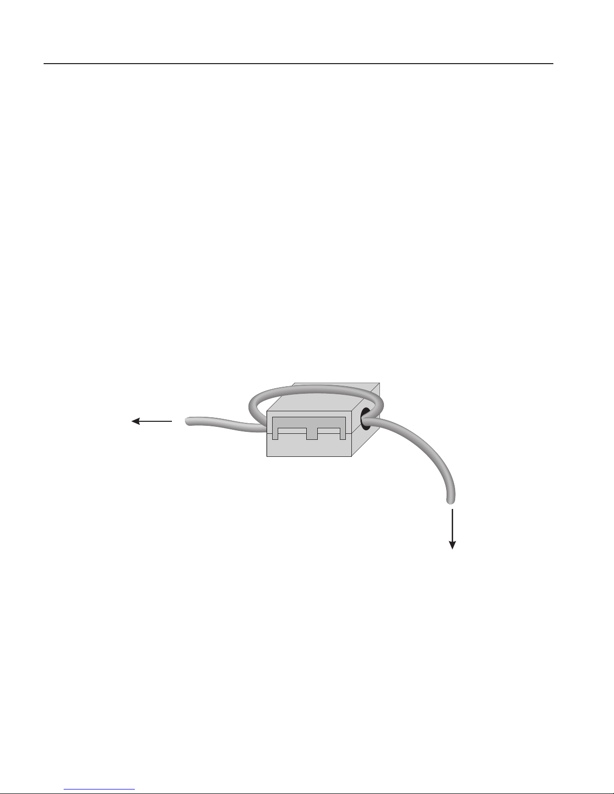
To attach a ferrite to a probe cable, make a loop in the cable near the connector and
clamp the ferrite around half of the loop as shown in the diagram. The ferrite can be
easily snapped open and moved to a new probe when needed.
Figure 1
clamp-on ferrite
connector
probe
Clamp-on ferrite installation
1.5.3 Emission Testing
The instrument fullls the limit requirements for Class A equipment. The instrument
was not designed to be used in domestic establishments.
1.5.4 Low Voltage Directive (Safety)
In order to comply with the European Low Voltage Directive (2006/95/EC), Beamex equipment has been designed to meet the EN 61010-1 and the EN 61010-2-010
standards.
Page 15

9
Before You Start
Authorized Service Centers
1.6 Authorized Service Centers
Please contact the following Authorized Service Center to coordinate service on your
Beamex product:
Beamex Oy Ab
Ristisuonraitti 10
FI-68600 Pietarsaari
Finland
When contacting a Service Centers for support, please have the following information
available:
Model Number
Serial Number
Voltage
Complete description of the problem
Page 16

Page 17

11
Specications and Environmental Conditions
Specications
2 Specications and Environmental Conditions
2.1 Specications
Table 2 Base Unit Specifications
Base Unit Specifications
FB150 FB350 FB660
Temperature Range at
23°C
–25°C to 150°C
(-13°F to 302°F)
33°C to 350°C
(91°F to 662°F)
50°C to 660°C
(122°F to 1220°F)
Display Accuracy ±0.2°C Full Range ±0.2°C Full Range ±0.35°C at 50°C
±0.35°C at 420°C
±0.5°C at 660°C
Stability ±0.01°C Full Range ±0.02 °C at 33°C
±0.02 °C at 200°C
±0.03°C at 350°C
±0.03°C at 50°C
±0.05°C at 420°C
±0.05°C at 660°C
Axial Uniformity at 40
mm (1.6 in)
±0.05°C Full Range ±0.04°C at 33°C
±0.1°C at 200°C
±0.2°C at 350°C
±0.05°C at 50°C
±0.35°C at 420°C
±0.5°C at 660°C
Axial Uniformity at 60
mm (2.4 in)
±0.07°C Full Range ±0.04°C at 33°C
±0.2°C at 200°C
±0.25°C at 350°C
±0.1°C at 50°C
±0.6°C at 420°C
±0.8°C at 660°C
Radial Uniformity ±0.01°C Full Range ±0.01°C at 33°C
±0.015°C at 200°C
±0.02°C at 350°C
±0.02°C at 50°C
±0.05°C at 420°C
±0.1°C at 660°C
Loading Effect (with
a 6.35 mm reference
probe and three 6.35
mm probes)
±0.006°C Full Range ±0.015°C Full Range ±0.015°C at 50°C
±0.025°C at 420°C
±0.035°C at 660°C
Loading Effect (versus
display with 6.35 mm
probes)
±0.08°C Full Range ±0.2°C Full Range ±0.1°C at 50°C
±0.2°C at 420°C
±0.2°C at 660°C
Hysteresis 0.025°C 0.06°C 0.2°C
Operating Conditions 0°C to 50°C, 0% to 90% RH (non-condensing)
Environmental
conditions for all
specications except
temperature range
13°C to 33°C
Immersion (Well) Depth 150 mm (5.9 in)
Insert OD 30 mm (1.18 in) 25.3 mm (1.00 in) 24.4 mm (0.96 in)
Heating Time 16 min: 23°C to 140°C
23 min: 23°C to 150°C
25 min: –25°C to 150°C
5 min: 33°C to 350°C 15 min: 50°C to 660°C
Cooling Time 15 min: 23°C to –25°C
25 min: 150°C to –23°C
32 min: 350°C to 33°C
14 min: 350°C to 100°C
35 min: 660°C to 50°C
25 min: 660°C to 100°C
Resolution 0.01°
Display LCD,°C or°F user-selectable
Key Pad Arrows, Menu, Enter, Exit, 4 soft keys
Size (H x W x D) 290 mm x 185 mm x 295 mm (11.4 x 7.3 x 11.6 in)
Page 18

FBXXX Field Temperature Block
Environmental Conditions
12
Base Unit Specifications
FB150 FB350 FB660
Weight 8.16 kg (18 lbs) 7.3 kg (16 lbs) 7.7 kg (17 lbs)
Power Requirements 100 V to 115 V (±10%)
50/60 Hz, 575 W
230 V (±10%) 50/60 Hz,
575 W
100 V to 115 V (±10%), 50/60 Hz, 1400 W
230 V (±10%), 50/60 Hz, 1800 W
System Fuse Ratings 115 V: 6.3 A T 250 V
230 V: 3.15 A T 250 V
15 A, 250 V Thermal Circuit Breakers
Computer Interface RS-232
Safety EN 61010-1:2001, CAN/CSA C22.2 No. 61010.1-04
Table 3 -R Option Specifications
-R Specifications
Built-in Reference Thermometer Readout
Accuracy
(4-Wire Reference Probe)
†
± 0.013 °C at -25 °C
± 0.015 °C at 0 °C
± 0.020 °C at 50 °C
± 0.025 °C at 150 °C
± 0.030 °C at 200 °C
± 0.040 °C at 350 °C
± 0.050 °C at 420 °C
± 0.070 °C at 660 °C
Reference Resistance Range 0 ohms to 400 ohms
Reference Resistance Accuracy‡ 0 ohms to 42 ohms: ±0.0025 ohms
42 ohms to 400 ohms: ±60 ppm of reading
Reference Characterizations ITS-90, CVD, IEC-60751, Resistance
Reference Measurement Capability 4-wire
†
The temperature range may be limited by the reference probe connected to the readout. The BuiltIn Reference Accuracy does not include the sensor probe accuracy. It does not include the probe
uncertainty or probe characterization errors.
‡
Measurement accuracy specications apply within the operating range and assume 4-wires for PRTs.
2.2 Environmental Conditions
Although the instrument has been designed for optimum durability and trouble-free
operation, it must be handled with care. The instrument should not be operated in an
excessively dusty or dirty environment. Maintenance and cleaning recommendations
can be found in the Maintenance section. The instrument operates safely under the following environmental conditions:
ambient temperature range: 0-50°C (32-122°F)
ambient relative humidity: 0 % to 90 % (non-condensing)
mains voltage: within ±10% of nominal
vibrations in the calibration environment should be minimized
altitude: less than 2,000 meters
indoor use only
Page 19

13
Quick Start
Setup
3 Quick Start
3.1 Setup
Note: The instrument will not heat, cool, or control until the “SET PT.”
parameter is “Enabled”.
Place the block on a at surface with at least 15 cm (6 in) of free space around the instrument. Overhead clearance is required. DO NOT place under a cabinet or structure.
Plug the instrument power cord into a mains outlet of the proper voltage, frequency,
and current capability (see Section 2.1, Specications, on page 11 for power details).
Observe that the nominal voltage corresponds to that indicated on the front of the
block.
Carefully place the insert into the well. Inserts should be of the smallest hole diameter possible still allowing the probe to slide in and out easily. Various insert sizes
are available. Contact an Authorized Service Center for assistance (see Section 1.6,
Authorized Service Centers, on page 9). The well must be clear of any foreign objects,
dirt and grit before an insert is installed. The insert is installed with the two small tong
holes positioned upward.
Turn on the power to the block by toggling the switch on the power entry module.
After a brief self-test, the controller should begin normal operation. The main screen
appears within 30 seconds. If the instrument fails to operate, please check the power
connection. The display shows the well temperature, and waits for user input before
further operation.
Press “SET PT.” and use the arrow keys to set the desired set-point temperature. Press
“ENTER” to save the desired set-point and enable the instrument. After ve (5) seconds, the instrument should start to operate normally and heat or cool to the designated
set-point.
Page 20
FBXXX Field Temperature Block
Parts and Controls
14
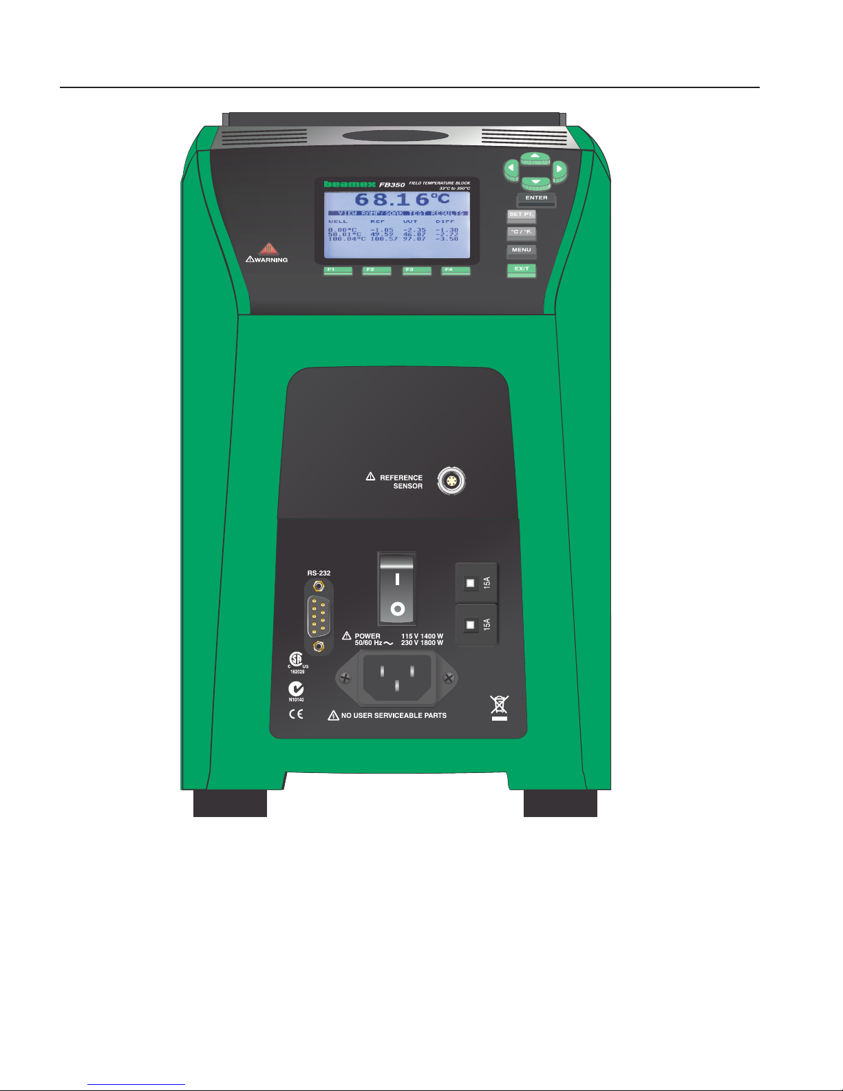
Figure 2 FBXXX Field Temperature Block
3.2 Parts and Controls
This section describes the exterior features of the Field Temperature Block. All interface and power connections are found on the front of the instrument (see Figure 2).
Page 21

15
Quick Start
Parts and Controls
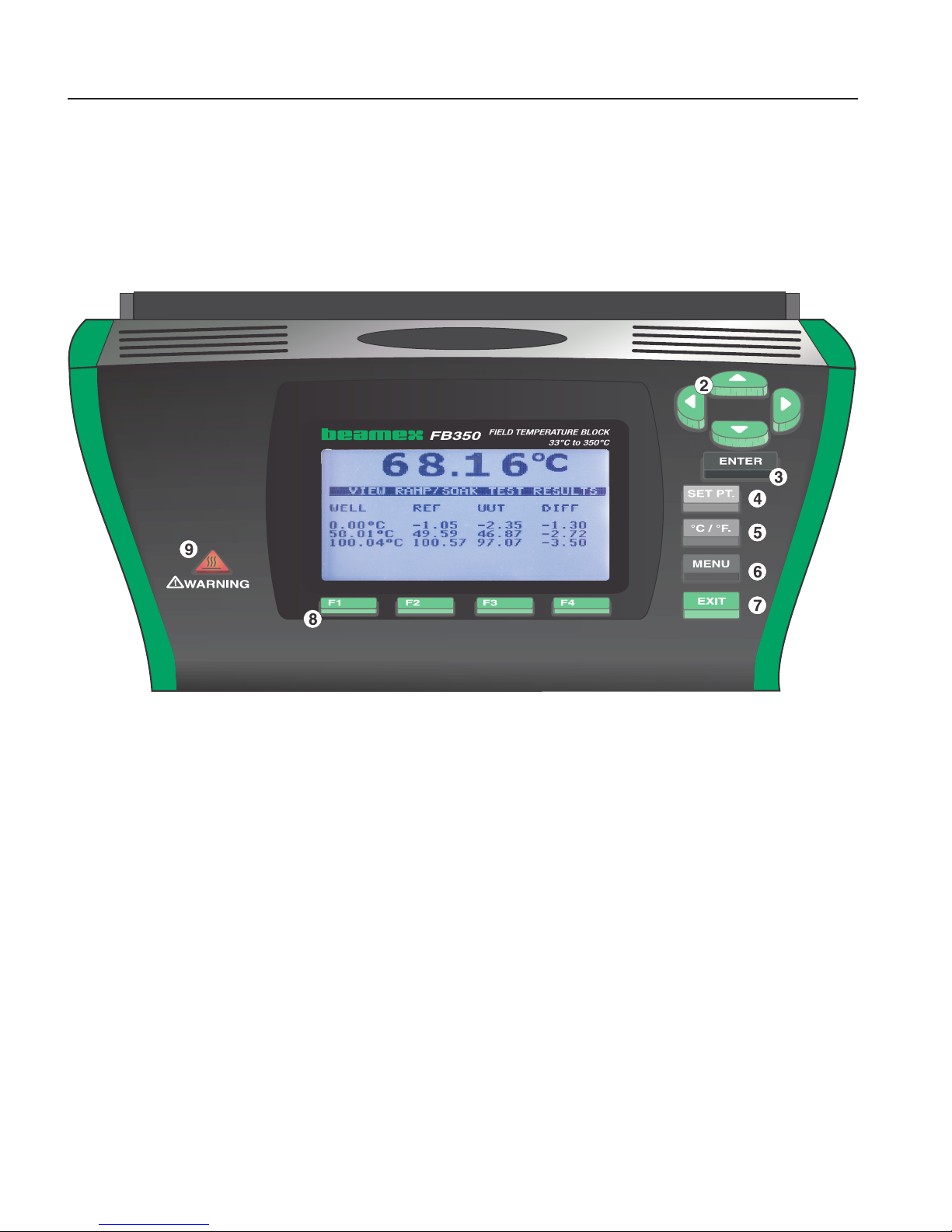
3.2.1 Display Panel
Figure 3 on next page shows the layout of the display panel.
Display (1)
The display is a 240 x 160 pixel monochrome graphics LCD device with a bright LED
backlight. The display is used to show current control temperature, measurements,
status information, operating parameters, and soft key functions.
udlr Arrow Keys (2)
The Arrow Keys allow you to move the cursor on the display, change the display layout, and adjust the contrast of the display. The contrast can only be adjusted using the
u and d arrow keys while viewing the main display window.
Enter Key (3)
The Enter Key allows you to select menus and accept new values.
SET PT. (4)
The Set Pt. Key allows you to enable the instrument to heat or cool to a desired setpoint. Until this key is enabled, the instrument will not heat or cool. It is in a “sleep”
state for safety of the operator and instrument.
°C/°F Key (5)
The °C/°F Key allows you to change the displayed temperature units from °C to °F
and vice versa.
Menu Key (6)
The Menu Key allows the user to access all parameter and settings menus. From the
main menu, the user can use the soft keys to access submenus and functions.
Exit Key (7)
The Exit Key allows you to exit menus and cancel newly entered values.
Soft Keys (8)
The Soft Keys are the four buttons immediately below the display (labeled F1 to F4).
The functions of the soft keys are indicated on the display above the buttons. The
function of the keys may change depending on the menu or function that is selected.
Page 22
FBXXX Field Temperature Block
Parts and Controls
16
Block Temperature Indicator (9)
The Block Temperature Indicator lamp allows users to know when the block temperature is safe (50°C to 60°C) to remove inserts or move the Field Temperature Block.
The indicator light is lit continuously once the block has exceeded approximately
50°C (varies 50°C to 60°C). The indicator light stays lit until the block cools to less
than approximately 50°C. If the instrument is disconnected from mains power, the
indicator light ashes until the block temperature is less than approximately 50°C.
Figure 3 Display panel and keys
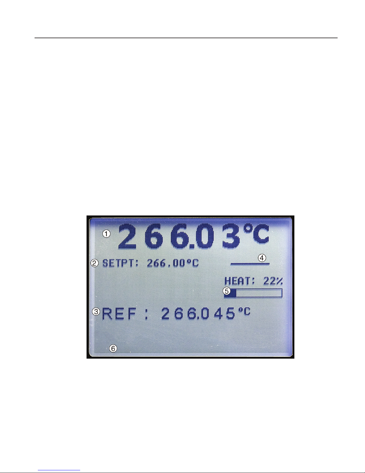
3.2.2 Display
The front panel display is shown in detail in Figure 4 on opposite page.
Heat Source Temperature (1)
The most recent block temperature measurement is shown in large digits in the box at
the top of the screen.
Set-point Temperature (2)
The current set-point temperature is displayed just below the Process Temperature.
Reference Thermometer Temperature (3) [-R models only]
When installed, the most recent reference thermometer measurement is shown on the
screen.
Page 23
17
Quick Start
Parts and Controls
Stability Status (4)
On the right hand side of the screen, you will nd a graph displaying the current status
of the stability of the Field Temperature Block.
Heating/Cooling Status (5)
Just below the stability graph there is a bar graph that will indicate HEATING, COOLING, or CUTOUT. This status graph indicates the current level of heating or cooling if
the instrument is not in cutout mode.
Soft Key Functions (6)
The four texts at the bottom of the display (not shown) indicate the functions of the
soft keys (F1–F4). These functions change with each menu.
Editing Windows
While setting up and operating the instrument, you are often required to enter or select
parameters. Editing windows appear on the screen when necessary to show the values
of parameters and allow edits.
Figure 4 FBXXX display
3.2.3 Power Panel
The following are found on the lower front panel of the instrument (see Figures 5 and
Figure 6 on page 19).
Page 24

FBXXX Field Temperature Block
Parts and Controls
18
Power Cord Plug (1)
The power supply cord attaches to the lower front power panel. Plug the cord into an
AC mains supply appropriate for the voltage range as specied in the specications
tables.
Power Switch (2)
For the FB150, the power switch is located on the power entry module of the unit at
the lower center of the power panel.
For the FB350 and FB660, the power switch is located between the RS-232 and the
circuit breakers.
Serial Connector (3)
On the FB150, the serial connector is a 9-pin subminiature D type located on the
power panel above the power entry module. On the FB350 and FB660, the serial
connector is a 9-pin subminiature D type located on the power panel to the left of the
power switch. The serial (RS-232) interface can be used to transmit measurements and
control the operation of the instrument.
Fuses
For the FB150, the fuses are located inside the power entry module of the unit (Figure
5 on opposite page).
If necessary, fuses must be replaced according to Specications (see Section 2.1,
Specications, on page 11.
Thermal Circuit Breakers (5)
For the FB350 and FB660, the thermal circuit breakers are separate from the power
connector (Figure 6 on opposite page). Circuit breakers can be reset by pressing the
button in the center of each circuit breaker.
Page 25

19
Quick Start
Parts and Controls
Figure 5 FB150 power panel
Figure 6 FB350 and FB660 power panel
Page 26

FBXXX Field Temperature Block
Parts and Controls
20
3.2.4 -R Option Panel (-R models only)
The -R (reference sensor) panel is the readout portion of the instrument and is only
available with -R models.
Figure 7 -R option panel
Reference Thermometer Connection (1)
The 6-pin Lemo smart connector on the front panel allows a reference probe to be attached to the instrument for use with the reference thermometer function of the instrument. The smart connector stores probe calibration coefcients. Using an adapter, the
6-pin Lemo will accept traditional connectors and the probe coefcients can be entered
into the readout or an appropriate characterization curve can be selected through the
user interface (see Section 1.5.2, Immunity Testing, on page 8 for information on using clamp-on ferrites).
A PRT is the only type of probe that is supported by the reference thermometer input.
The PRT (RTD or SPRT) probe connects to the reference thermometer input using a
6-pin Lemo connector. Figure 8 shows how a four-wire probe is wired to the 6-pin
Lemo connector. One pair of wires attaches to pins 1 and 2 and the other pair attaches
to pins 4 and 5 (pins 1 and 5 source current and pins 2 and 4 sense the potential). If
a shield wire is present, it should be connected to pin 3, which is also used for the
memory circuit. Pin 6 is only used for the memory circuit.
Page 27

21
Quick Start
Languages
Figure 8
5 4
2
1
Memory
3
6
Pin 1
Excitation
Current –
Pin 2
Sense –
Pin 3
Memory –
(GND)
Pin 4
Sense +
Pin 5
Current +
Pin 6
Memory +
Pre-assembled
inside connector
PRT
Probe connector wiring
A two-wire probe can also be used with the reference thermometer. It is connected
by attaching one wire to both pins 1 and 2 of the plug and the other wire to both pins
4 and 5. If a shield wire is present, it should be connected to pin 3. Accuracy may be
signicantly degraded using a two-wire connection because of lead resistance.
3.3 Languages
The display on Field Temperature Blocks can be set to different languages depending
on the conguration.
Page 28

FBXXX Field Temperature Block
Languages
22
European: English, French, Spanish, Italian, German
Russian: Russian, English
Asian: English, Chinese, Japanese
3.3.1 Language Selection
Select the language to be displayed by following the steps shown in Figure 9 on this
page.
Figure 9 Steps to language selection
3.3.2 Reset to English Language
If you are in a language and need a short cut exit, press F1 and F4 simultaneously to
reset the display to English.
To reset to your originally selected language after resetting to English, follow the steps
in Figure 9 on this page.
Note: The F1 and F4 English shortcut override is temporary. If you toggle the
power off, the instrument will return to the language selected in the DISPLAY
SETUP menu rather than coming up in English.
Page 29

23
Menu Structure
Temp Setup Menu
4 Menu Structure
4.1 Temp Setup Menu
Figure 10
FB150/ FB350/ FB660 MAIN MENU
F1 F2 F3 F4
TEMP SETUP PROG MENU SYSTEM MENU INPUT SETUP (-R ONLY)
F1 Setup
Scan Rate: <edit> Degrees per minute at which the Block increases or decreases temperature
Stability Limit: <edit> The defined minimum stability over a 2 minute period before alarm is activated
Stability Alarm: (ON/OFF) <select> Audible alarm indicating Block is stable
F2 View Cutout
Soft Cutout: <edit> User adjustable safety cutout
Hard Cutout: <View Only> Factory set safety cutout
Hot Keys (while viewing main screen)
SETPoinT- Set Point Key
Setpoint: <Edit> Set point temperature
ENTER – <Enable control of the unit>
F1 – SELECT PRESET <1-8> <select>
F1 – EDIT PRESETS <1-8> <edit>
F4 – SAVE/DISABLE System <disables control of instrument>
ºC / ºF Key - Units: <°C, °F> Changes temperature units
Up/ Down Arrow Keys <toggle> <adjust contrast>
Up Key: Darker
Down Key: Lighter
F1 & F4 Keys (Same Time)
< Reset to English Language >
F1 & F3 Keys (Same Time)
< Turn off key press beep >
Code Update Mode Keys
ENTER & EXIT Keys (hold during power up) <initiate code update mode> Allows instrument software to be updated
Main Menu - Temp SetUp
Page 30

FBXXX Field Temperature Block
Prog Menu
24
4.2 Prog Menu
Figure 11
FB150/ FB350/ FB660 MAIN MENU
F1 F2 F3 F4
TEMP SETUP PROG MENU SYSTEM MENU INPUT SETUP (-R ONLY)
F1 RUN PROGram
TEST STATUS: < OFF, RUN><select> Changes status of current test
RUN TEST: < RAMP/SOAK > Runs selected test
RECORD DATA: <YES/NO> <select> (-R Only) Records data for ramp/soak
TEST ID: (Text, 16 char, English ASCII only > (-R Only) Alpha-numeric identification for test
F2 Ramp & Soak
No. of SETPOINTS:<1-8><select>
SOAK TIME: <Minutes><edit> Length of time in minutes at which the Block remains at the set point temperature
Number of CYCLES: <1 – 99> <edit> Number of times the Block repeats the ramp/soak program
DIRECTION: < → ,( Down arrow)> <select>
PASS TOLERANCE: <edit> (-R only) Pass/Fail criteria for the ramp/soak program
F1 SET POINTS
SETPOINT 1: <edit> °C
SETPOINT 2: <edit> °C
SETPOINT 3: <edit> °C
SETPOINT 4: <edit> °C
SETPOINT 5: <edit> °C
SETPOINT 6: <edit> °C
SETPOINT 7: <edit> °C
SETPOINT 8: <edit> °C
F3 TEST RESULT (-R Only)
F1 VIEW TESTS
DISPLAY TEST: <1 - 16><Select> Displays test results
DATE: <view only>
TIME: <view only>
F2 PRINT TESTS
PRINT TEST: <NO, YES><select> Print all test data to to RS-232 port
F3 ERASE TESTS
Erase Tests: <No, Yes><select>, Erases all tests
Main Menu - Prog Menu
Page 31

25
Menu Structure
System Menu
4.3 System Menu
Figure 12
FB150/ FB350/ FB660 MAIN MENU
F1 F2 F3 F4
TEMP SETUP PROG MENU SYSTEM MENU INPUT SETUP (-R ONLY)
F1 System Setup
F1 DISPLAY SETUP
LANGUAGE: <English, Japanese, Chinese, German, Spanish, French, Russian, Italian> <Select>
DECIMAL: <PERIOD, COMMA><Select>
KEY AUDIO: <ON, OFF> <select>
F2 COMMunication SETUP
BAUD RATE: <1200, 2400, 4800, 9600, 19200, 38000>
LINEFEED: <ON, OFF> <Select>
F3 DATE TIME (-R Only)
TIME: <edit> (Military Time Only)
DATE (Adjust): <edit>
REPORT DATE: <(mm/dd/yyyy), (dd,mm,yyyy)><Select>
F2 PASSWORD
USER PASSWORD: <edit>
PROTECTION : <LOW, HIGH><select>
F3 CALIBration
F1 CALPOINTS
TEMPerature 1: <edit>
TEMPerature 2:
<edit>
TEMPerature 3:
<edit>
GRADient 1: <edit>
GRADient 2: <edit>
GRADient 3: <edit>
GRADient 4: <edit> (FB660 only)
GRADient 5: <edit> (FB660 only)
F2 CONTRoller
TEMPerature Proportional Band: <edit>
TEMPerature INTegration:
<edit>
TEMPerature DERivative:
<edit>
F3 CALibration REFerance
(-R only)
REF C0: <edit>
REF C100:
<edit>
IINPUT CALibration DATE:
<edit>
F4 SYSTEM INFO <View only>
MODEL: <View only>
SERIAL number: <View only>
Firm Ware VERsion: <View only>
CALibration DATE: <View only>
INPUT CALibration DATE: <View only> (-R only)
Main Menu - System Menu
Page 32

FBXXX Field Temperature Block
Input Setup (-R only)
26
4.4 Input Setup (-R only)
Figure 13
FB150/ FB350/ FB660 MAIN MENU 10
F1 F2 F3 F4
TEMP SETUP PROG MENU SYSTEM MENU INPUT SETUP (-R ONLY)
F1 REFerence INPUT
F1 PROGram PROBE
SERIAL number: <edit> <alpha-numeric>
INPUT CALibration DATE: <edit>
PROBE TYPE:
<ITS-90,CVD,IEC 60751,Resistance><select>
List:
ITS-90 CVD IEC 60751 Resistance
RTPW R0
A Alpha
B Beta
C Delta
A4
B4
PROGRAM probe <YES, NO> <password required to program probe>
F2 TEST reference CALibration
RESISTANCE: <edit> Ω
TEMPERATURE:
<Calculated value displayed> <view only> °C
Main Menu - Input Setup
Page 33

27
Controller operation
Main Screen
5 Controller operation
This chapter discusses in detail how to operate the Field Temperature Block temperature controller and/or thermometer readout using the front control panel. Using
the front panel keys and liquid crystal display (LCD) the user may monitor the well
temperature, set the temperature set-point in °C or °F, monitor the heater output
power, monitor the stability, set the cutout set-point, set the operating parameters, and
congure the communication interface. For the -R model, the user has full control of
thermometer readout functions of the instrument using the front panel keys and the
LCD. A diagram of the full menu structure can be found in Section 4, Menu Structure,
on page 23. When active, menu keys are selected using the soft keys (F1-F4).
5.1 Main Screen
The LCD on the front panel allows direct viewing of the control temperature (actual
well temperature), reference thermometer temperature (-R model only), heating or
cooling power, stability state, current set-point information, and current program information. The temperature displayed is either in °C or °F. The displayed temperature
units can easily be changed by pressing the C/F key on the front panel.
HEAT SOURCE TEMPERATURE
This is the temperature of the block as measured by the control sensor. The controller
heats or cools the block to force the control temperature equal to the set-point.
SET-POINT (SETPT)
This is the current set-point.
REFERENCE TEMPERATURE (REF) (-R model only)
This is the temperature measured by an external reference thermometer attached to the
Reference Thermometer 6-pin Smart Lemo input.
CONTROL - STAB (Stability)
This shows the stability of the block. When the stability is within the set limit this line
is at.
CONTROL - HEAT/COOL
This shows the relative heating or cooling power (duty cycle) in percent.
HEATING, COOLING, CUTOUT
This shows the status of heating or cooling or the cutout when activated. The bar graph
indicates the relative heating or cooling power.
Page 34

FBXXX Field Temperature Blocks
Main Menu
28
5.2 Main Menu
The MAIN MENU is accessed through the MENU button and allows access to all
main submenus. The submenus allow the user to setup the instrument as desired and to
change system parameters as needed.
5.2.1 Temp Setup
The TEMP SETUP menu contains Field Temperature Block functions related to temperature setup.
5.2.1.1 Setup
5.2.1.1.1 SCAN RATE
The SCAN RATE parameter can be set such that when the set-point is changed, the
Field Temperature Block heats or cools at a specied rate, degrees per minute, (°C/min
or °F/min) until it reaches the new set-point.
The Scan Rate can be set from 0.1 to 500 °C/min (0.2 to 900 °F/min). However, the
maximum scan rate is limited by the natural heating or cooling rate of the instrument,
which will be less than the maximum setting, especially when cooling.
The Scan Rate can be adjusted using the arrow keys. Once the scan rate has been set,
press “ENTER” to set the new scan rate.
5.2.1.1.2 STABLE LIMIT
NOTE: The Field Temperature Block should not be expected to operate better
than the stability specification set forth in the Specifications section of this
guide. Therefore, the minimum setting of the stability limit should not be less
than the stability specification.
The STABLE LIMIT parameter allows the instrument to notify the user when it has
achieved the stability limit set in this parameter. There are two notications: visual
and audible. The visual notication is always active. When the instrument is operating
within the stability limit, the stability graph on the main screen remains at once the
instrument is within the given specication, otherwise the graph indicates the instrument is not yet stable. The audible, if enabled, alerts the user once per set-point when
the instrument achieves the set stability limit. Use the arrow keys to set the desired
stability limit and press “ENTER” to accept the new stability limit.
Example:
A specic calibration process requires the instrument to operate within ±0.1°C. “0.1”
would be entered into the stability limit parameter. When the instrument’s stability is
within ±0.1°C, the graph is at and the audible alarm (if enabled) noties the user that
the instrument is operating within ±0.1°C. Use the arrow keys to set the desired stability limit and press “ENTER” to accept the new stability limit.
Page 35

29
Controller operation
Main Menu
5.2.1.1.3 STABLE ALARM
The audible alarm described in STABLE LIMIT is turned on or off using the STABLE
ALARM parameter. Select the either “Enable” or “Disable” using the left or right arrow keys and press “ENTER” to accept the selection.
5.2.1.2 CUTOUT
The view CUTOUT contains the Cutout functions of the instrument.
5.2.1.2.1 SOFT CUTOUT
The SOFT CUTOUT is user settable. As a protection against software or hardware
fault or user error, the block is equipped with the adjustable cutout device that shuts
off power to the heat source if the well temperature exceeds a set value. It is factory
set as a default ten degrees above the high limit of the instrument. The user should
set the Soft Cutout according to the temperature limits of the probes being calibrated.
The Soft Cutout can act as a safety barrier to protect probes from being over heated
to temperatures beyond their specied temperature limits if the Soft Cutout is set appropriately for probes under test. This feature protects the instrument and probes from
excessive temperatures.
If the cutout is activated because of excessive well temperature, power to the heat
source shuts off and the instrument cools. The heat source remains in cutout mode
and active heating and cooling is disabled until the user manually resets the cutout. If
the over-temperature cutout has been triggered, the instrument displays “CUTOUT”
above the duty cycle bar graph, which indicates a cutout condition. The instrument
remains in cutout mode until the temperature is reduced and the cutout is reset. The
well temperature must drop a few degrees below the cutout set-point before the cutout
can be reset.
For safety reasons, the cutout only has one mode — manual reset. Manual reset mode
means the cutout must be reset by the operator after the temperature falls below the
set-point.
The SOFT CUTOUT parameter can be set to any temperature over the range of the
instrument. The cutout should be set within 5-10° of the safety limit of the equipment
being calibrated or used with the Field Temperature Block.
NOTE: CUTOUT RESET: If the Field Temperature Block exceeds the
temperature set in the soft cutout menu or if it exceeds the maximum operating
temperature of the instrument, a cutout condition occurs. If this happens, the
instrument enters cutout mode and will not actively heat or cool until the user
resets the instrument.
To reset the cutout, the instrument temperature must cool to lower than the cutout setpoint. Once the instrument has cooled the user may reset the instrument by pressing
“SET PT.” and pressing “ENTER” to engage instrument.
Page 36

FBXXX Field Temperature Blocks
Main Menu
30
5.2.1.2.2 HARD CUTOUT
The HARD CUTOUT parameter is a view only function and indicates the factory setting for the hard cutout. The Hard Cutout is not user settable.
5.2.2 Prog Menu
The PROG MENU (PROGRAM MENU) allows access to the automated and manual
program selections.
5.2.2.1 RUN PROG
The RUN PROG (RUN PROGRAM) allows the user to access program status
features.
5.2.2.1.1 TEST STATUS
The TEST STATUS option controls the state of the program. The user selects to Run
the program or to turn the program Off.
5.2.2.1.2 RECORD DATA
The RECORD DATA option allows the user to select to record the data from the test
(Yes) or not to record data (No).
5.2.2.1.3 TEST ID
The TEST ID (Identication) allows the user to enter a Test ID number for the current
test. The Test ID can be an alpha numeric entry up to 16 characters in length.
5.2.2.2 RAMP/SOAK
The RAMP/SOAK feature automatically cycles the Field Temperature Block between
temperatures while holding at each temperature for the length of time set by the user.
5.2.2.2.1 NO. SETPOINTS
The NO. SETPOINTS is the number of set-points dened for a given program. The
number of set-points for each program can be set from 1 to 8 and vary depending on
the needs of the user. Set the maximum number of set-points needed for the program
selected. Once the number of set-points is selected, press “ENTER” to accept the new
setting.
5.2.2.2.2 SOAK TIME
The SOAK TIME parameter is the number of minutes that each of the program setpoints is maintained. The time starts when the temperature settles to within the specied stability. The stability limit is set in the TEMP SETUP|SETUP|STABLE LIMIT
window.
Page 37

31
Controller operation
Main Menu
5.2.2.2.3 NO. CYCLES
The NO. CYCLES parameter is the number of times that the program is repeated.
5.2.2.2.4 DIRECTION
The DIRECTION parameter controls whether the set-points are sequenced in one
direction, 1-8, or both directions, 1-8 and 8-1, before the sequence is repeated. If the
both directions option is selected, the program sequences from the rst set-point to the
last and then reverses direction sequencing from the last to the rst.
5.2.2.2.5 PASS TOLERANCE
The PASS TOLERANCE is the allowable tolerance condition for the test and is used
to highlight test points that have large errors.
5.2.2.2.6 SETPOINTS
The SETPOINTS menu allows the user to set each of the set-points for the program.
Only the number of set-points dened by NO SETPOINTS will be displayed. Setpoints can be quickly selected using the Up/Down arrow keys to scroll through the setpoints. Press “Enter” to activate the set-point and make it editable. Once editable, use
the Up/Down arrow keys to enter the values and the Left/Right arrow keys to scroll
through the digits in the value. Press “Enter” to accept the value entered.
5.2.2.2.6.1 SETPOINT 1 – SETPOINT 8 (Depending on NO. SETPOINTS defined)
The SETPOINT n parameter is the designated temperatures for the set-points selected
for the program.
5.2.2.3 TEST RESULTS
The TEST RESULTS MENU allows the user access to the tests parameters.
5.2.2.3.1 VIEW TESTS
The VIEW TESTS menu allows the user to view the results of up to 16 tests.
5.2.2.3.1.1 TEST ID
The TEST ID (TEST IDENTIFICATION) parameter allows the user to select from 16
tests to view.
5.2.2.3.1.2 TYPE
The TYPE parameter allows the user to select between viewing Ramp & Soak results.
5.2.2.3.1.3 DATE (VIEW ONLY)
The DATE the selected test was performed.
Page 38

FBXXX Field Temperature Blocks
Main Menu
32
5.2.2.3.1.4 TIME (VIEW ONLY)
The TIME the selected test was performed.
5.2.2.3.1.5 RESULTS (press ENTER)
The RESULTS menu is the second part of the VIEW TESTS menu and allows the user
to view the results of the selected test.
5.2.2.3.1.5.1 RAMP & SOAK
5.2.2.3.1.5.1.1 TEST ID
The TEST ID (TEST IDENTIFICATION) parameter allows the user to select from 16
tests to view.
5.2.2.3.1.5.1.2 WELL
The WELL (WELL TEMPERATURE) result provides the temperature of the dry-well
as measured by the control sensor.
5.2.2.3.1.5.1.3 REF
The REF (REFERENCE) result provides the temperature of the reference probe.
5.2.2.3.2 PRINT TESTS
The PRINT TESTS parameter allows the user to the option to print the selected test
results. YES enables the print option. NO disables the print option.
5.2.2.3.3 ERASE TESTS
The ERASE TESTS option is unconditionally password protected. The user has the
choice, YES/NO, to erase all of the stored tests. A warning is presented to the user
stating that all tests will be erased.
5.2.3 System Menu
The System Menu allows the user to set up the display settings, communications protocol, date/time settings (-R model only), password settings, calibrations settings, and
view system information.
5.2.3.1 SYSTEM SETUP
The SYSTEM SETUP menu contains the Display Setup, Communications Setup, and
Date/Time Setup (-R model only).
Page 39

33
Controller operation
Main Menu
5.2.3.1.1 DISPLY SETUP
The DISPLY SETUP (DISPLAY SETUP) parameter contains the language selection,
decimal separator, and keypad sound parameters.
5.2.3.1.1.1 LANGUAGE
The LANGUAGE parameter is used to set the display language. Use the right or left
arrow key to select the preferred language and press “ENTER” to accept the selection.
The user needs to exit from the SYSTEM MENU window in order for the change in
language selection to take affect.
NOTE: If the wrong language is selected, return to the Main Screen by holding
EXIT for a few seconds. Once the Main Screen is displayed, simultaneously
press and hold F1 and F4 to set to English temporarily. Then return to the
DISPLAY SETUP screen and set the correct language.
5.2.3.1.1.2 DECIMAL
The DECIMAL parameter is used to determine the decimal separator, a comma or a
period. Select the desired decimal separator using the right or left arrow key and press
“ENTER” to accept the selection.
5.2.3.1.1.3 KEY AUDIO
The KEY AUDIO parameter (F1 and F3 Keys pressed simultaneously) enables or
disables the key press beep.
5.2.3.1.2 COMM SETUP
The COMM SETUP (COMMUNICATIONS SETUP) menu contains the serial interface parameters. The parameters in the menu are—BAUD RATE and LINEFEED.
5.2.3.1.2.1 BAUD RATE
The BAUD RATE parameter determines the serial communication transmission rate or
baud rate.
BAUD may be programmed to 1200, 2400, 4800, 9600, 19200, or 38400 baud.
5.2.3.1.2.2 LINEFEED
The LINEFEED enables (On) or disables (Off) transmission of a line feed character
(LF, ASCII 10) after transmission of any carriage-return. The LINEFEED default setting is on. The line feed parameter can be turned on or off as needed by the user.
Page 40

FBXXX Field Temperature Blocks
Main Menu
34
5.2.3.1.3 DATE TIME (-R model only)
The DATE TIME menu allows the user to set the format for the date and time. Additionally, the user sets the date and time for the date and time stamp function.
5.2.3.1.3.1 TIME
The TIME parameter allows the user to set the internal time for the instrument. The
time is tracked using a 24-hour clock. To set the time, press “Enter” and use the arrow
keys to set the time and press “Enter” to accept the selection.
5.2.3.1.3.2 DATE
The DATE parameter allows the user to enter the date for the date/time stamp function. Press “Enter” to access the parameter. Use the arrow keys to enter the date and
press “Enter” to accept the selection.
5.2.3.1.3.3 REPORT DATES
The REPORT DATES parameter allows the user to select the date format. Use the
left and right arrow keys to choose the date format, mm/dd/yyyy or dd/mm/yyyy, and
press “Enter” to accept the selection.
5.2.3.2 PASSWORD
The PASSWORD (PASSWORD SETUP) menu is used to set the system password or
set the level of protection that conditional engages or disengages protection of certain
groups of parameters.
5.2.3.2.1 USER PASSWORD
The USER PASSWORD parameter allows the users to enter and change the system
and conditional password used to access protected menus. The Password is a number
between one and four digits. Each digit of the password can be a number from 0 to
9. The default System Password is “1234”. If desired, the System Password can be
changed in this menu by using the numeric keys to enter the new password and pressing “ENTER”.
5.2.3.2.2 PROTECTION
The PROTECTION parameter is used to enable (HIGH) or disable (LOW) password
protection for the conditional parameters. The password is the same as the system
password. The user has to option to conditionally password protect the Soft Cutout,
Ramp & Soak, and Probe Prog. The user selects to “HIGH” or “LOW” the conditional password using the left and right arrow keys and presses “Enter” to accept the
selection.
Page 41

35
Controller operation
Main Menu
5.2.3.3 CALIB
CAUTION: Calibration parameters must be correct for the instrument to
function properly.
The CALIB (CALIBRATION) menu allows the user access to the calibration parameters for the instrument. Access to the heat source and readout calibration parameters
is protected by a password. Calibration parameters are programmed at the factory
when the instrument is calibrated. These parameters may be adjusted to improve the
accuracy of the instrument by qualied personnel.
CAUTION: DO NOT change the values of the control parameters from the
factory set values unless you are recalibrating the instrument. The correct
setting of these parameters is important to the safe and proper operation of the
block.
The parameters in the CALIB menu are set at the factory and must not be altered unless recalibrating the instrument. Recalibration of the instrument should be performed
by trained, knowledgeable personnel. The correct values are important to the accuracy
and proper and safe operation of the block. Access to these parameters is protected by
a password. In the event that the calibration parameters need to be reentered into the
instrument, these constants and their settings are listed in the Report of Calibration
shipped with the instrument.
5.2.3.3.1 CAL POINTS
The CAL POINTS (CALIBRATION POINTS SETUP) menu contains the heat source
calibration constants, TEMP CALPT 1, TEMP CALPT 2, and TEMP CALTPT 3. Use
the arrow keys to enter the set-point for each calibration point and press “Enter” to
accept the entry. The calibration points should be selected applicable to model with a
low, mid-range, and high set-point.
5.2.3.3.1.1 TEMP 1
The TEMP 1 parameter is the offset in °C for the heat source accuracy at the 1st calibration point.
5.2.3.3.1.2 TEMP 2
The TEMP 2 parameter is the offset in °C for the heat source accuracy at the 2nd
calibration point.
5.2.3.3.1.3 TEMP 3
The TEMP 3 parameter is the offset in °C for the heat source accuracy at the 3rd calibration point.
Page 42

FBXXX Field Temperature Blocks
Main Menu
36
5.2.3.3.1.4 GRAD 1
The GRAD 1 parameter is ratio for the top zone heater control for the axial gradient
calibration at the 1st calibration point.
5.2.3.3.1.5 GRAD 2
The GRAD 2 parameter is ratio for the top zone heater control for the axial gradient
calibration at the 2nd calibration point.
5.2.3.3.1.6 GRAD 3
The GRAD 3 parameter is ratio for the top zone heater control for the axial gradient
calibration at the 3rd calibration point.
5.2.3.3.1.7 GRAD 4 (FB660 only)
The GRAD 4 parameter is a ratio for the top zone heater control for the axial gradient
calibration at the fourth calibration point.
5.2.3.3.1.8 GRAD 5 (FB660 only)
The GRAD 5 parameter is a ratio for the top sone heater control for the axial gradient
calibration at the fth calibration point.
5.2.3.3.1.9 CALDATE
The CALDATE parameter is the calibration date for the heat source. Use the arrow
keys to enter the calibration date in the format selected in DATE FORMAT.
5.2.3.3.2 CONTRL
The CONTRL (CONTROL SETUP) menu is used to access the controller parameters.
5.2.3.3.3 TEMP PB
The TEMP PB parameter is the main zone proportional band and the gain in °C that
the instrument’s proportional-integral-derivative (PID) controller uses for main zone
control.
5.2.3.3.3.1 TEMP INT
The TEMP INT parameter is the main zone integral, which is the integration time in
seconds that the instrument’s PID controller uses for main zone control.
5.2.3.3.3.2 TEMP DER
The TEMP DER parameter is the main zone derivative, which is the derivative time in
seconds that the instrument’s PID controller uses for main zone control.
Page 43

37
Controller operation
Main Menu
5.2.3.3.4 CAL REF (-R model only)
The CAL REF (REFERENCE INPUT CALIBRATION) menu is used to access the
reference PRT calibration parameters. Use these parameters to adjust the measurement
at 0 and 100Ω.
5.2.3.3.4.1 REF1C0
The REF1C0 parameter is the rst calibration point for the reference resistance.
5.2.3.3.4.2 REF1C100
The REF1C100 parameter is the second calibration point for the reference resistance.
5.2.3.3.4.3 INPUT CAL DATE
The INPUT CAL DATE parameter is the calibration date for the readout. Use the arrow keys to enter the calibration date in the format selected in DATE FORMAT.
5.2.3.4 SYSTEM INFO (view only)
The SYSTEM INFO (SYSTEM INFORMATION) menu displays manufacturer information regarding the instrument.
5.2.3.4.1 MODEL
The MODEL parameter displays the model number of the instrument.
5.2.3.4.2 SERIAL
The SERIAL (SERIAL NUMBER) parameter displays the serial number of the
instrument.
5.2.3.4.3 FW VER
The FW VER (FIRMWARE VERSION0 parameter displays the rmware version
used in the instrument.
5.2.3.4.4 CAL DATE
The CAL DATE (CALIBRATION DATE) parameter displays the calibration date of
the heat source.
5.2.3.4.5 INPUT CAL DATE (-R model only)
The INPUT CAL DATE (-R CALIBRATION DATE) parameter displays the calibration date for the readout or the -R module.
Page 44

FBXXX Field Temperature Blocks
Main Menu
38
5.2.4 INPUT SETUP (-R model only)
The INPUT SETUP menu allows all the parameters related to the -R module or
readout function of the instrument to be accessed. The parameters found in this menu
affect the performance, accuracy and display type of the reference PRTs.
5.2.4.1 REF INPUT
The REF INPUT (REFERENCE INPUT) menu contains the parameters for the
reference input to the readout module of the instrument. The Reference Input is only
compatible with PRTs with ITS-90, Callendar Van-Dusen, or IEC-60751 coefcients.
Additionally, the Reference Input will read straight resistance.
The probe serial number and coefcients can be found on the calibration certicate
that was shipped with the probe. If the probe requires calibration, contact an Authorized Service Center to inquire about calibration services.
5.2.4.1.1 PROG PROBE
The PROG PROBE (REFERENCE PROBE SETUP) menu is used to setup the reference probe parameters.
5.2.4.1.1.1 SERIAL
The SERIAL (SERIAL NUMBER) parameter allows the user to enter ten digit alpha
numeric serial number for the reference probe. Character range = {0-9, A-Z, ‘-‘,
<Blank>}. Minimum required is 1 character.
When a blank space is entered, any characters after the blank are dropped. For example, change S/N 1234-5678 to S/N TEST1. Enter TEST1<Blank Space>678. The
serial number will drop the last three characters and enter the S/N TEST1.
5.2.4.1.1.2 CAL DATE
The CAL DATE parameter is used to enter the calibration date for the reference
probe. Use the arrow keys to enter the calibration date in the format selected in DATE
FORMAT.
5.2.4.1.1.3 PROBE TYPE
The PROBE TYPE parameter is used to choose which probe conversion type to be
setup. Use the left and right arrow keys to select the conversion type and press “Enter”
to accept selection.
5.2.4.1.1.3.1 TYPE (ITS-90)
The TYPE parameter can be ITS-90, Callendar Van-Dusen (CVD), IEC-60751, or
Resistance. The ITS-90 option is for PRTs calibrated and characterized using the International Temperature Scale of 1990 (ITS-90) equations. Subranges 4, and 7 through 11
are supported. The parameters that appear when ITS-90 is selected are “Serial” (Serial
Number), “Cal Date”, “RTPW”, “COEF A”, “COEF B”, “COEF C”, “COEF A4”,
Page 45

39
Controller operation
Main Menu
and “COEF B4”. These should be set with the corresponding values that appear on
the calibration certicate of the PRT. The parameter “RTPW” takes the triple point of
water resistance, often labeled “R0.01” or “R(273.16K)” on the certicate. Parameters
“COEF A”, “COEF B”, “COEF C” take the an, bn and cn coefcients where n is a
number from 7 to 11. Parameters “COEF A4” and “COEF B4” take the a4 and b4 coefcients on the certicate. Any ITS-90 parameter of the instrument that does not have a
corresponding coefcient on the PRT’s certicate must be set to 0.
The following table (Table ) shows which parameter to set for each of the coefcients
that may appear on the certicate. The example that follows demonstrates how to set
the ITS-90 parameters for certain cases.
Table 4 Matching Certificate Values to ITS-90 Coefficients
ITS-90 Coefficient Certicate Value
COEF A a7, a8, a9, a10, or a11
COEF B b7, b8, b9, or 0
COEF C c7 or 0
COEF A4 a4
COEF B4 b4
NOTE: If the certificate has two sets of coefficients, one set for “zero-power”
calibration and one set for 1 mA calibration, use the coefficients for the 1 mA
calibration.
Example 1:
A PRT was calibrated to ITS-90 and its calibration certicate states values for coefcients Rtpw, a4, b4, a8, and b8. Set the instrument’s parameters with values from the
certicate as follows.
Table 5 Setting Coefficients Rtpw, a8, b8, and b4
Coefficient Certicate Value
RTPW Rtpw
COEF A a8
COEF B b8
COEF C 0
COEF A4 a4
COEF B4 b4
5.2.4.1.1.3.1.1 PROG PROBE
The PROG PROBE parameter is used to tell the instrument to program a Smart Lemo
with the appropriate probe coefcients. Use the arrow keys to select “Yes” or “No”.
If “Yes” is selected, the Smart Lemo will be programmed with the appropriate coefcients for the selected conversion type. For ITS-90 and CVD, the coefcient values
need to entered before programming the Smart Lemo. For IEC-60751 and Resistance,
no values are required to program the Smart Lemo.
Page 46

FBXXX Field Temperature Blocks
Main Menu
40
5.2.4.1.1.3.2 TYPE (CVD)
The CVD (Callendar-Van Dusen) conversion is for RTD probes that use the CallendarVan Dusen equation:
The parameters that appear when CVD is selected are “Serial” (Serial Number),
“Cal Date”, “R0”, “ALPHA”, “DELTA” and “BETA”, which can be set by the user.
For IEC-751, DIN-43760 or ASTM E1137 sensors, the coefcients for R0, ALPHA,
DELTA, and BETA are 100.0, 0.00385055, 1.4998, and 0.1086 respectively.
Some probes may be provided with A, B, and C coefcients for the Callendar-Van
Dusen equation in the following form:
The A, B, and C coefcients can be converted to Alpha, Beta and Delta coefcients
using the following equation:
5.2.4.1.1.3.2.1 PROG PROBE
The PROG PROBE parameter is used to tell the instrument to program a Smart Lemo
with the appropriate probe coefcients. Use the arrow keys to select “Yes” or “No”.
If “Yes” is selected, the Smart Lemo will be programmed with the appropriate coefcients for the selected conversion type. For ITS-90 and CVD the coefcient values
need to entered before programming the Smart Lemo. For IEC-60751 and Resistance,
no values are required to program the Smart Lemo.
5.2.4.1.1.3.3 TYPE (IEC-60751)
The IEC-60751 conversion is for RTD probes that use the International Electrotechnical Commission (IEC) Standard Publication 751.
Page 47

41
Controller operation
Main Menu
5.2.4.1.1.3.3.1 PROG PROBE
The PROG PROBE parameter is used to tell the instrument to program a Smart Lemo
with the appropriate probe coefcients. Use the arrow keys to select “Yes” or “No”.
If “Yes” is selected, the Smart Lemo will be programmed with the appropriate coefcients for the selected conversion type. For ITS-90 and CVD the coefcient values
need to entered before programming the Smart Lemo. For IEC-60751 and Resistance,
no values are required to program the Smart Lemo.
5.2.4.1.1.3.4 TYPE (RESISTANCE)
The RESISTANCE option displays the resistance, in ohms, of the selected reference
probe. This temporarily overrides the temperatue conversion. The temperature conversion type can be restored without losing coefcients.
5.2.4.1.2 TEST CALC
The TEST CALC (TEST REFerance CALCULATION) allows the technician to test
the output of a specic conversion algorithm. Simply select the conversion type and
enter a value for the requested parameter. Press ENTER, the algorithm computes the
answer, and it is displayed immediately in the parentheses at the bottom of the screen,
TEMPERATURE: XX.XXX.
Page 48

Page 49

43
Digital communication interface
Wiring
6 Digital communication interface
The Field Temperature Block is capable of communicating with and being controlled
by other equipment through the RS-232 digital interface.
With a digital interface the instrument may be connected to a computer or other equipment. This allows the user to input the set-point temperature, monitor the temperature,
communicate with the readout to obtain measurement data, control operating conditions and access any of the other controller functions, all using remote communications equipment. The RS-232 serial interface allows serial digital communications
over fairly long distances. With the serial interface, the user may access any of the
functions, parameters and settings discussed in this section.
6.1 Wiring
The serial communications cable attaches to the instrument through the DB-9 connector at the front of the instrument. Figure 14 on next page, shows the pin-out of this
connector and suggested cable wiring. To eliminate noise, the serial cable should be
shielded with low resistance between the connector (DB9) and the shield.
6.1.1 Setup
Before operation the serial interface must rst be set up by programming the BAUD
rate and other conguration parameters. These parameters are programmed within
the communications menu. The serial interface parameters can be accessed from the
main menu by MENU|SYSTEM MENU|SYSTEM SETUP|COMM SETUP|. For more
information on the serial interface parameters, see Section 5.2.3.1.2COMM SETUP on
page 33.
6.1.2 Serial Operation
The serial communications uses 8 data bits, one stop bit, and no parity. The setpoint and other commands may be sent via the serial interface to set the temperature
set-point and view or program the various parameters. The interface commands are
discussed in the “Digital Interface” section.
Page 50

FBXXX Field Temperature Block
Command Syntax
44
Figure 14 RS-232 wiring
6.2 Command Syntax
Field Temperature Blocks accept commands for setting parameters, executing functions or responding with requested data. These commands are in the form of strings of
ASCII-encoded characters. As far as possible, the Field Temperature Block command
syntax conforms to SCPI-1994. One notable exception is that compound commands
are not allowed as explained below.
Commands consist of a command header and, if necessary, parameter data. All commands must be terminated with either a carriage return (ASCII 0D hex or 13 decimal)
or new line character (ASCII 0A hex or 10 decimal).
Command headers consist of one or more mnemonics separated by colons (:). Mnemonics may use letter characters, the underscore character (_), and possibly numeric
digits as well. Commands are not case sensitive. Mnemonics often have alternate
Page 51

45
Digital communication interface
Commands by Function or Group
forms. Most mnemonics have a long form that is more readable and a short form consisting of three or four characters that is more efcient.
A mnemonic may end with a numeric sufx that species one of a set of independent
function blocks such as input channel data paths. If a numeric sufx is omitted when a
particular block must be specied, an error is generated (“Header sufx out of range”).
Query commands are commands that request data in response. Query commands have
a question mark (?) immediately following the command header. Responses to query
commands are generated immediately and placed in the output buffer. Responses are
then transmitted automatically over the RS-232 port. Responses are lost if not read
before the next command is received.
Some commands require parameter data to specify values for one or more parameters.
The command header is separated from the parameter data by a space (ASCII 20 hex
or 32 decimal). Multiple parameters are separated by a comma(,).
Field Temperature Blocks do not allow compound commands (multiple commands per
line separated with semicolons). All commands are sequential. The execution of each
command is completed before subsequent commands are processed.
6.3 Commands by Function or Group
In this section, the commands are arranged into the following groups:
Calibration Commands – commands for Field Temperature Block calibration
parameters.
Main Screen Commands – commands for parameters displayed on the main screen.
Program Commands – commands for program setup and status.
Reference Commands – commands for accessing reference thermometer parameters.
Setup Commands – commands for setting up communication, display, password,
measure, and operation parameters.
System Commands – commands to report and change the status of the instrument.
Temperature Commands – commands for control temperature and cutout functions.
Table 6 Commands by Function or Group
SCREEN
PARAMETER Command
Password Protection
Group Read/Write
Calibration - Controller TEMP PB SOUR:LCON:PBAN Unconditional R/W
TEMP INT SOUR:LCON:INT Unconditional R/W
TEMP DER SOUR:LCON:DER Unconditional R/W
CALDATE CAL:DATE:UNIT Unconditional R/W
Page 52

FBXXX Field Temperature Block
Commands by Function or Group
46
SCREEN
PARAMETER Command
Password Protection
Group Read/Write
Calibration – Heat Source TEMP 1 SOUR:SENS:CAL:PAR1 Unconditional R/W
TEMP 2 SOUR:SENS:CAL:PAR2 Unconditional R/W
TEMP 3 SOUR:SENS:CAL:PAR3 Unconditional R/W
GRAD 1 SOUR:SENS:CAL:GRAD1 Unconditional R/W
GRAD 2 SOUR:SENS:CAL:GRAD2 Unconditional R/W
GRAD 3 SOUR:SENS:CAL:GRAD3 Unconditional R/W
GRAD 4 SOUR:SENS:CAL:GRAD4 Unconditional R/W
GRAD 5 SOUR:SENS:CAL:GRAD5 Unconditional R/W
TEMP 1 SOUR:SENS:CAL:TEMP1 N/A R
TEMP 2 SOUR:SENS:CAL:TEMP2 N/A R
TEMP 3 SOUR:SENS:CAL:TEMP3 N/A R
Calibration – Reference
(-R model only)
REF1C0 SENS1:CAL:PAR1 Unconditional R/W
REF1C100 SENS1:CAL:PAR2 Unconditional R/W
INPUT CAL DATE CAL:DATE:MOD Unconditional R/W
Main Screen (none) SOUR:SENS:DATA N/A R
SETPT SOUR:SPO N/A R/W
STAB SOUR:STAB:DAT N/A R
STAB graph SOUR:STAB:TEST N/A R
HEAT % OUTP1:DATA N/A R
(none) OUTP2:DATA N/A R
ENABLE OUTP1:STAT N/A R/W
(-R model only) REF CALC1:DATA N/A R
(-R model only) REF TEMP READ, MEAS, FETC N/A R
Program – Run TEST STATUS PROG:STAT N/A R/W
Program - List (none) PROG:CAT N/A R
Program - Select (none) PROG:TYP N/A R/W
Program - Setup TEST ID PROG:IDEN N/A R/W
(none) PROG:MEM:COUN N/A R
Erase Tests ERASE TESTS PROG:MEM:CLEA Unconditional W
Ramp & Soak RAMP/SOAK SETUP PROG:SEQ:CAT N/A R
SETPOINT n PROG:SEQ:PAR SPOn Conditional R/W
SOAK TIME PROG:SEQ:PAR DWEL Conditional R/W
SETPOINTS PROG:SEQ:PAR POIN Conditional R/W
NO CYCLES PROG:SEQ:PAR CYCL Conditional R/W
PASS TOLERANCE PROG:SEQ:PAR PTOL Conditional R/W
DIRECTION PROG:SEQ:PAR DIR Conditional R/W
SETPOINT 1 SOUR:LIST:SPO1 N/A R/W
SETPOINT 2 SOUR:LIST:SPO2 N/A R/W
SETPOINT 3 SOUR:LIST:SPO3 N/A R/W
SETPOINT 4 SOUR:LIST:SPO4 N/A R/W
SETPOINT 5 SOUR:LIST:SPO5 N/A R/W
SETPOINT 6 SOUR:LIST:SPO6 N/A R/W
SETPOINT 7 SOUR:LIST:SPO7 N/A R/W
SETPOINT 8 SOUR:LIST:SPO8 N/A R/W
Test – Results (-R model
only)
PRINT TEST PROG:MEM:PRINT N/A W
ERASE TESTS PROG:MEM:CLEA Unconditional W
Page 53

47
Digital communication interface
Commands by Function or Group
SCREEN
PARAMETER Command
Password Protection
Group Read/Write
Reference - List (-R model
only)
PROBE TYPE CALC1:CONV:CAT N/A R
Characterization
Parameters - Active List
(-R model only)
(none) CALC1:CONV:PAR:CAT N/A R
CAL DATE CALC1:CONV:DATE Conditional R/W
PROGRAM CALC1:CONV:PROG Unconditional W
Reference – Setup (-R
model only)
PROBE TYPE: ITS-90 CALC1:CONV:NAME ITS-90 Conditional R/W
Reference – Setup (-R
model only)
PROBE TYPE: CVD CALC1:CONV:NAME CVD Conditional R/W
Reference – Setup (-R
model only)
PROBE TYPE: IEC CALC1:CONV:NAME IEC-751 Conditional R/W
Reference – Setup (-R
model only)
CONV TYPE:
RESISTANCE
CALC1:CONV:NAME RES Conditional R/W
(-R model only) SERIAL CALC1:CONV:SNUM Conditional R/W
ITS90 (-R model only) RTPW CALC1:CONV:PAR:VAL
RTPW
Conditional R/W
A CALC1:CONV:PAR:VAL A7 Conditional R/W
B CALC1:CONV:PAR:VAL B7 Conditional R/W
C CALC1:CONV:PAR:VAL C7 Conditional R/W
A4 CALC1:CONV:PAR:VAL A4 Conditional R/W
B4 CALC1:CONV:PAR:VAL B4 Conditional R/W
CVD (-R model only) R0 CALC1:CONV:PAR:VAL R0 Conditional R/W
ALPHA CALC1:CONV:PAR:VAL AL Conditional R/W
DELTA CALC1:CONV:PAR:VAL DE Conditional R/W
BETA CALC1:CONV:PAR:VAL BE Conditional R/W
RESISTANCE SENS1:DATA N/A R
Reference – Test Algorithm
(-R model only)
TEST CALC CALC1:CONV:TEST N/A R
Setup - Communication BAUD RATE SYST:COMM:SER:BAUD N/A R/W
LINEFEED SYST:COMM:SER:LIN N/A R/W
Setup - Display LANGUAGE SYST:LANG N/A R/W
DECIMAL SYST:DEC:FORM N/A R/W
KEY AUDIO SYST:BEEP:KEYB N/A R/W
Setup - Password PASSWORD (Disable) SYST:PASS:CDIS Unconditional W
PASSWORD (Enable) SYST:PASS:CEN Unconditional W
Status (none) SYST:PASS:CEN:STAT N/A R
USER PASSWORD SYST:PASS:NEW Unconditional W
PROTECTION SYST:PASS:PROT N/A R/W
Setup – Date/Time DATE SYST:DATE Unconditional R/W
TIME SYST:TIME Unconditional R/W
System - Setup °C/°F key UNIT:TEMP N/A R/W
Heat Enable (none) OUTP:STAT N/A R/W
(none) SYST:KLOC Conditional R/W
(none) SYST:CONF:MOD N/A R
Page 54

FBXXX Field Temperature Block
Serial Commands - Alphabetic Listing
48
SCREEN
PARAMETER Command
Password Protection
Group Read/Write
System - Information (none) SYST:ERR N/A R
(all) *IDN N/A R
(none) *CLS N/A W
(none) *OPT N/A R
FW VER SYST:COD:VERS N/A R
(none) SYST:BEEP:IMM N/A W
Temperature – Cutout HARD CUTOUT SOUR:PROT:HCUT N/A R
SOFT CUTOUT SOUR:PROT:SCUT:LEV Conditional R/W
Reset (none) SOUR:PROT:CLE N/A W
Trip State (none) SOUR:PROT:TRIP N/A R
Temperature - Setup SCAN RATE SOUR:RATE N/A R/W
STABLE LIMIT SOUR:STAB:LIM N/A R/W
STABLE ALARM SOUR:STAB:BEEP N/A R/W
6.4 Serial Commands - Alphabetic Listing
Each command description provides the structure (long and short format), a description of the command purpose, a command example, an example of what the command
returns (as applicable to query commands), and notes specic to the command. The
following apply to each group of commands:
Numeric data, specied by the mnemonic, <num>, uses ASCII characters to
represent numbers. Numbers may contain a plus or minus (‘+’ or ‘-’) sign,
decimal point (‘.’), and exponent (‘E’ or ‘e’) with its sign. If a fractional
component is received when only an integer is required, the number is rounded
to the nearest integer without any resulting error message. The mnemonics DEF,
MIN, and MAX are often acceptable for the default, minimum, and maximum
value respectively. Unit sufxes, such as V or OHM, can be appended to
numeric parameters and are accepted without error but ignored.
Unrecognized commands or commands with incorrect syntax or invalid
parameters generate error messages in the error queue.
Upper case letters designate syntax that is required when issuing the command.
Lower case letters are optional and may be omitted.
< > indicates a required parameter.
[ ] indicates optional parameters.
( ) indicates a group of parameters that must be used together.
For query commands, specifying the MIN, MAX, or DEF parameter causes
the instrument to respond with the minimum, maximum, or default setting
respectively.
For set commands, specifying the MIN, MAX, or DEF parameters causes the
instrument to use the minimum, maximum, or default setting respectively.
‘|’ indicates alternate parameter values.
<n> indicates a number is required.
<num> indicates numeric value is required.
<prog> indicates a program number (SEQ<n> or SWIT<n>) is required.
Page 55

49
Digital communication interface
Serial Commands - Alphabetic Listing
<bool> indicates a Boolean value (0 or 1) is required. The mnemonics OFF and
ON are also accepted for 0 and 1, respectively.
<conv> indicates a conversion mnemonic is required.
<param> indicates a parameter name is required.
<seri> indicates a serial number is required.
<res> indicates a resistance value is required.
<volt> indicates a voltage value is required.
<unit> indicates a temperature unit is required.
<temp> indicates a temperature °C/F is required.
<pass> indicates a password is required.
<port> indicates a port number is required.
<label> indicates an eight character label is required.
<year> indicates a four digit number is required.
<month> indicates a one or two digit number is required.
<day> indicates a one or two digit number is required.
<hour> indicates a one or two digit number is required.
<minute> indicates a one or two digit number is required.
<second> indicates a one or two digit number is required.
<baud> indicates a valid baud number is required.
*CLS
Clear the status registers
Example: *CLS
This command has no response.
Clears all status registers (events, operations etc).
*IDN?
Read the product information (Manufacturer, Model Number, Serial Number, and
Firmware Version)
Example: *IDN?
Response: BEAMEX,FB150,A79002,1.00
*OPT?
Read the product conguration, reference hardware enabled (1) or not (0) (see
SYST:CONF:MOD) plus Russian conguration set (2) or not (0)
Example: *OPT?
Response: 1
Page 56

FBXXX Field Temperature Block
Serial Commands - Alphabetic Listing
50
This command is a read only command and returns the state of the reference functionality (0, 1).
CAL:DATE:MOD[?] [<year>,<month>,<day>] (-R model only)
NOTE: This command is unconditionally protected, which requires a password
to set it.
Read or set the calibration date for the -R Module (INPUT CALibration DATE) where
the entered values are all numeric and “yyyy” is a four digit year (2000-2135), “mm”
is a two digit month (1-12), and “dd” is a two digit day (1-31)
Read Example: CAL:DATE:MOD?
Response: 2007,05,24
Set Example: CAL:DATE:MOD 2007,12, 30
This command reads or sets the calibration date for the -R module including all accompanying sensors.
CAL:DATE:UNIT[?] [<year>,<month>,<day>]
NOTE: This command is unconditionally protected, which requires a password
to set it.
Read or set the calibration date for the Main Unit where the entered values are all numeric and “yyyy” is a four digit year (2000-2135); default 2007, “mm” is a two digit
month (1-12), and “dd” is a two digit day (1-31)
Read Example: CAL:DAT:UNIT?
Response: 2007,05,24
Set Example: CAL:DAT:CAL 2006,12, 30
This command reads or sets the calibration date for the Main Unit. Calibration is for
the heat source portion of the instrument.
CALC1:CONV:CAT? (-R model only)
Read the list of reference probe characterization methods, “CVD, I90, IEC, RES”
Example: CALC1:CONV:CAT?
Response: “CVD”,”I90”,”IEC”,”RES”
Provides the list of PRT/RTD characterization methods available.
Page 57

51
Digital communication interface
Serial Commands - Alphabetic Listing
CALC1:CONV:DATE[?] [<yyyy,mm,dd>] (-R model only)
NOTE: This command is conditionally protected, which requires a password to
set it.
Read or set the Smart Lemo probe calibration date in yyyy,mm,dd format
Year Range = {2000 – 2135}; Default: 2007
Month Range = {1 – 12}; Default: 1
Day Range = {1 – 31}; Default: 1
Read Example: CALC1:CONV:DATE?
Response: 2007,10,09
Set Example: CALC1:CONV:DATE 2007,09,06
This command reads or sets the calibration date for the Smart Lemo probe.
CALC1:CONV:NAME[?][n] (-R model only)
NOTE: This command is conditionally protected, which requires a password to
set it.
Read or set the reference probe characterization method where “n” is an alpha
numeric value; CVD, I90, IEC, and RES. Range={ITS90, CVD, IEC, RES} or 0-3,
Default:ITS90
Read Example: CALC1:CONV:NAME?
Response: CVD
Set Example: CALC1:CONV:NAME I90
Reads or sets the reference probe characterization method from a predened set of
options.
CALC1:CONV:PAR:CAT? (-R model only)
Read the list of active reference probe characterization parameter names
Example: CALC1:CONV:PAR:CAT?
Response: “RTPW”,”A”,“B”,“C”,“A4”,“B4”
This command is a read only command, which returns the active parameters for the
current reference probe type.
Page 58

FBXXX Field Temperature Block
Serial Commands - Alphabetic Listing
52
CALC1:CONV:PAR:VAL[?] par[,<n>] (-R model only)
NOTE: This command is conditionally protected, which requires a password to
set it.
Read or set a reference probe characterization parameter. Where “par” is a parameter
identied as follows: ITS90: RTPW, A7, B7, C7, A4, B4; or CVD: AL, DE or BE. “n”
may be some real number or an exponential value such as -1.234567e-5 for ITS-90
ITS-90 Ranges: {RTPW, A7, B7, A4, B4} or 0 - 5
RTPW = 1.0 to 200 ohms
Coefcients = ± 0.010
Defaults: RTPW = 100
All ITS-90 coefcients = 0.00000
CVD Ranges/Defaults: {R0, AL, DE, BE} or 0 - 3
R0 = 1.0 to 200.00 ohms
R0 Default = 100.00
AL Range = 0.1 to 0.9
AL Default = 0.00385055
BE Range = 0.0 to 1.0
BE Default = 0.10863
DE Range = 0.0 to 2.0
DE Default = 1.499786
Read Example: CALC1:CONV:PAR:VAL? RTPW
Response: 100.4545
Set Example: CALC:CONV:PAR:VAL A7, 0.00385075
This command returns a reference probe characterization parameter as desired by the
user.
CALC1:CONV:PROG (-R model only)
NOTE: This command is unconditionally protected, which requires a password
to set it.
Program the Smart Lemo probe with the current probe settings
Example: CALC1:CONV:PROG
Page 59

53
Digital communication interface
Serial Commands - Alphabetic Listing
CALC1:CONV:SNUM[?] <ser_num> (-R model only)
NOTE: This command is conditionally protected, which requires a password to
set it.
Read or set the reference probe serial number, where “ser_num” character range
equals {0-9, A-Z, ‘-‘}, up to 10 characters in length with a minimum of 1 character
length. Default: “0”
When a blank space is entered, any characters after the blank are dropped. For example, change S/N 1234-5678 to S/N TEST1. Enter TEST1<Blank Space>678. The
serial number will drop the last three characters and enter the S/N TEST1.
Read Example: CALC1:CONV:SNUM?
Response: 1234
Set Example: CALC1:CONV:SNUM 1560-D
This command allows the user to read or enter a reference probe serial number.
CALC1:CONV:TEST[?] <n>]
Test the conversion algorithm from resistance (ohms) to temperature (°C or °F). “n” is
the value to be converted (ohms); entry for “n” is required for converted output. Range
= {0-500}; Default = 100
Read Example: CALC1:CONV:TEST? 100.000
Response: 0.0100
This is a read only command and tests conversion algorithm from resistance to
temperature.
CAL1:DATA? (-R model only)
Reads the reference sensor Temperature. The returned value will be in degrees °C
(°F) if a temperature value is returned. The value may be resistance depending on the
conversion selection
Example: CALC1:DAT?
Response: 325
The command returns an instantaneous reading of the reference sensor Temperature.
OUTP:STAT[?] [0|1]
Read or set the Main Heat output enable, off [0] or on [1]
Read Example: OUTP:STAT?
Response: 0
Set Example: OUTP:STAT 1
Page 60

FBXXX Field Temperature Block
Serial Commands - Alphabetic Listing
54
This command reads or sets the active heating or cooling output status. A “0” is returned if the output status is off, and a “1” is returned if the output status is on
OUTP1:DATA?
Read the main heat output percent
Example: OUTP1:DATA?
Response: 18.0
This command returns the current main zone heater duty cycle
OUTP2:DATA?
Read the gradient heat output percent
Example: OUTP2:DATA?
Response: 57.0
This command returns the current top zone heater percent power.
PROG:CAT?
A catalog list of all dene programs: Ramp & Soak = SEQ
Example: PROG:CAT?
Response: “SEQ”
PROG:IDEN[?] [n]
Read or set the program identier. Character range = {0 – 9, A – Z, ‘-‘}, up to 12 characters, minimum 1 character: Default: “0”
Read Example: PROG:IDEN?
Set Example: TEST-1
PROG:MEM:CLE (-R Model only)
NOTE: This command is unconditionally protected, which requires a password
to set it.
Erase all test reports stored in NVMemory
Example: PROG:MEM:CLE
PROG:MEM:COUN? (-R Model only)
Read the test report count.
Example: PROG:MEM:COUN? 6
Page 61

55
Digital communication interface
Serial Commands - Alphabetic Listing
Provide the count for the number of test reports currently stored in memory.
PROG:MEM:PRIN [n] [ALL] (-R Model only)
Prints one or ALL test reports. Where “n” indicates the test report to be printed and 1
is the earliest test.
Example: PROG:MEM:PRINT 1
PROG:SEQ:CAT?
Read a list of program parameters for Ramp & Soak tests
Example: PROG:SEQ:CAT?
Response: “SPOn”,”DWELL”,”DIR”,”POIN”,”CYCL”,”PTOL”
This command provides a list of the parameters for the Ramp and Soak test.
PROG:SEQ:PAR? par[,<n>]
Read or set a program parameter for Ramp & Soak tests. Range = {SPOn, DWELL,
DIR, POIN, CYCL, PTOL}.
Table 7 PROG:SEQ:PAR parameters
Parameter Min Max Default
SPO[n]* 1 8 1
DWEL 1 100 15
POIN 1 8 8
CYCL 1 999 1
PTOL 0.01 99.9 1.00
DIR 0 (up) 1 (U/D) 0
*Read Only, must be <= # of setpoints (POIN)
Read Example: PROG:SEQ:PAR? dwell
Response: 25
Set Example: PROG:SEQ:PAR cycle,8
Reads or sets a specied parameter in the Ramp & Soak test.
PROG:STAT[?] [0|1]
Read or set the execution state for the selected program. (Off=0, Run=1) Default = 0
Read Example: PROG:STAT?
Response: 0
Set Example: PROG:STAT 1
Page 62

FBXXX Field Temperature Block
Serial Commands - Alphabetic Listing
56
If the selected program is not running then a value of 0 is returned otherwise a 1 is
returned.
PROG:TYPE[?] [ <prog>]
Read or select a program to run where “prog” is a name, SEQ. Default = SEQ
Read Example: PROG:TYPE?
Response: SEQ
Set Example: PROG:TYPE SEQ
Reads or selects the current program setting, Ramp & Soak = SEQ.
READ?, MEAS? or FETC? (-R model only)
Read the Reference sensor temperature, °C or °F
Example: READ?
Response: 264.262
If the external reference probe is enabled, the reference temperature is returned otherwise 0.0 is returned.
SENS1:CAL:PAR<n>[?][cal] (-R model only)
NOTE: This command is unconditionally protected, which requires a password
to set it.
Read or set a reference input calibration parameter where “n” is a value of 1 or 2 corresponding to the calibration parameters REF1C0 and REF1C100 respectively. “cal” is
a real number used as the calibration offset for the respective parameter
REF1C0 Range = {-1.0 to 1.0}
REF1C100 Range = {-2.0 to 2.0}
Defaults (all): 0.0000
Read Example: SENS:CAL:PAR1?
Response: 0.2
Set Example: SENS1:CAL:PAR2 0.092
Reference thermometer input commands to verify or set REF1C0 (PAR1) or REF1C100 (PAR2) calibration parameters.
SENS1:DATA? (-R model only)
Read the reference input resistance
Example: SENS1:DATA?
Page 63

57
Digital communication interface
Serial Commands - Alphabetic Listing
Response: 199.9366
This command returns the resistance in ohms of the reference probe.
SOUR:LCON:DER[?] [n]
NOTE: This command is unconditionally protected, which requires a password
to set it.
Read or set the main control loop derivative time in seconds, Min: 0.0, Max: 99.9
Read Example: SOUR:LCON:DER?
Response: 1.5
Set Example: SOUR:LCON:DER 5
The main zone derivative is the derivative time in seconds that the instrument’s PID
controller uses for main zone control.
SOUR:LCON:INT[?] [n]
NOTE: This command is unconditionally protected, which requires a password
to set it.
Read or set the main control loop integral time in seconds. Range = {10.0-999.9}
Read Example: SOUR:LCON:INT?
Response: 20.0
Set Example: SOUR:LCON:INT 10
The main zone integral is the integration time in seconds that the instrument’s PID
controller uses for main zone control.
SOUR:LCON:PBAN[?] [n]
NOTE: This command is unconditionally protected and requires a password to
set it.
Read or set the main control loop proportional band, °C. Range = {1.0-99.9}
Read Example: SOUR:LCON:PBAN?
Response: 1.5
Set Example: SOUR:LCON:PBAN 7
The main zone proportional band is the gain in °C that the instrument’s proportionalintegral-derivative (PID) controller uses for main zone control.
Page 64

FBXXX Field Temperature Block
Serial Commands - Alphabetic Listing
58
SOUR:LIST:SPO<i>[?] [n]
Read or set a main temperature preset set-point
Read example: SOUR:LIST:SPO6?
Response: 25.00
Set Example: SOUR:LIST;SPO6 100.00
This sets the preset set-points found in PROG MENU under RAMP/SOAK.
SOUR:PROT:HCUT?
Read the hard cutout temperature set-point in °C or °F
Read Example: SOUR:PROT:HCUT?
Response: 140
Returns the current value of the hard cutout set-point.
SOUR:PROT:CLEA
Reset the cutout to enable the system
Example: SOUR:PROT:CLEA
This command has no response.
If the Field Temperature Block exceeds the temperature set in the soft cutout menu or
if it exceeds the maximum operating temperature of the instrument, a cutout condition
occurs. If this happens, the instrument enters cutout mode and will not actively heat
or cool until the user issues this command to clear the cutout or resets the instrument
using the Setpt. key to clear the cutout mode and activate the instrument.
SOUR:PROT:SCUT:LEV[?] [n]
NOTE: This command is conditionally protected and requires a password to set
it.
Read or set the soft cutout set-point where “n” is an integer value from 0 to 700
FB150 Range = {–25.00 to 165.00}
FB350 Range = {25.00 to 365.00}
FB660 Range = {25.00 to 670.00}
Read Example: SOUR:PROT:SCUT:LEV?
Response: 125
Set Example: SOUR:PROT:SCUT:LEV 450
Read or set the soft cutout set-point. The soft cutout should be set to protect the temperature limits of the instruments under test.
Page 65

59
Digital communication interface
Serial Commands - Alphabetic Listing
SOUR:PROT:TRIP?
Read the temperature cutout tripped state. Range = {0, 1}; 0 = No Cutout; 1 = Cutout
Example: SOUR:PROT:TRIP?
Response: 0
A value of 0 is returned if the cutout set point has not been reached. Otherwise a value
of 1 is returned and the cutout set point has been reached.
SOUR:RATE[?] [n]
Read or set the control temperature rate of change (Scan Rate), °C or °F per minute.
Min: 0.10, Max: 500.00; Default: 100.00
Read Example: SOUR:RATE?
Response: 0.531
Set Example: SOUR:RATE 1.26
The response to this command starts out high initially and decreases as the set point is
reached.
SOUR:SENS:CAL:GRAD<x>[?] [n]
NOTE: This command is unconditionally protected and requires a password to
set it.
Read or set the axial gradient control parameter, where “x” is a numeric value indicating the parameter. [1] = GRAD1 = GRAD 1, [2] = GRAD2 = GRAD 2, [3] = GRAD3
= GRAD 3, [4] = GRAD4 = GRAD 4, [5] = GRAD5 = GRAD 5. “n” is a real number
ranging from -1.0 to 1.0 entered as a ratio of the main heater power
Read Example: SOUR:SENS:CAL:GRAD2?
Response: 0.05
Set Example: SOUR:SENS:CAL:GRAD2 0.08
The top zone heater reacts as a ratio of the mains heater power to control the axial
gradient.
SOUR:SENS:CAL:PAR<x>[?] [n]
NOTE: This command is unconditionally protected and requires a password to
set it.
Read or set a control temperature calibration parameter, where “x” is a numeric value
indicating the parameter. [1] = PAR1=Temp 1,PAR2=Temp 2, PAR3=Temp 3. “n” is
the entered value of the parameter. Range = ±50.00; Defaults: 0.000
Page 66

FBXXX Field Temperature Block
Serial Commands - Alphabetic Listing
60
Read Example: SOUR:SENS:CAL:PAR1?
Response: 0.0
Set Example: SOUR:SENS:CAL:PAR2 0.02
This command reads or sets the calibration parameter value for main control.
SOUR:SENS:CAL:TEMP<x>?
Read the required calibration temperature (°C) corresponding to a calibration parameter where “x” is a numeric value indicating the parameter [1] = TEMP1, [2] = TEMP2,
AND [3] = TEMP3. Range = {1-3}; Default = 1
Example: SOUR:SENS:CAL:TEMP1?
Response: 40
SOUR:SENS:DATA? [TEMP]
Read the control temperature, °C or °F
Example: SOUR:SENS:DATA? or SOUR:SENS:DATA? TEMP
Response: 30.285°C (current control temp)
The current control temperature is returned if the above or if TEMP is appended to the
end of the example.
SOUR:SENS:DATA? [RES]
Read the control sensor resistance
Example: SOUR:SENS:DATA? RES
Response: 111.28
When RES is appended to the end of the example above, the internal sensor resistance
is returned.
SOUR:SPO[?] [n]
Set the control set-point, °C or °F, where “n” is a real value with acceptance limits
based on the model
Parameter Min Max Default
FB150 –25.00 150.00 25.00
FB350 25.00 350.00 25.00
FB660 25.00 660.00 25.00
Read Example: SOUR:SPO?
Response: 50.000
Page 67

61
Digital communication interface
Serial Commands - Alphabetic Listing
Set Example: SOUR:SPO 100.00
This command reads or sets the value of the control set point based on the system
temperature units.
SOUR:STAB:BEEP[?] [n]
Read or set the stability alert (beep) enable where “n” is a value 0 or 1. [0] is disable,
[1] is enable beep. Default:1 (Enable Beep)
Read Example: SOUR:STAB:BEEP?
Response: 1
Set Example: SOUR:STAB:BEEP 0
Enable or disable the audible stability alert.
SOUR:STAB:DAT?
Read the control temperature stability, °C or °F
Example: SOUR:STAB:DAT?
Response: 0.306
The controller stability is returned.
SOUR:STAB:LIM[?] [n]
Read or set the control temperature stability limit, °C or °F where “n” is a positive real
value. Range = {0.01 to 9.99 (°C)}; Default: 0.05 (°C)
Read Example: SOUR:STAB:LIM?
Response: 0.05
Set Example: SOUR:STAB:LIM 0.03
Read or set the control stability limit.
SOUR:STAB:TEST?
Read the temperature stability test results. Stable = 1; Unstable = 0
Example: SOUR:STAB:TEST?
Response: 0
A value of 0 is returned if the controller is not stable at the current set-point. Otherwise
a value of 1 is returned if the controller is stable at the current set-point.
SYST:BEEP:IMM
Beep the system beeper
Example: SYST:BEEP:IMM
Page 68

FBXXX Field Temperature Block
Serial Commands - Alphabetic Listing
62
The system beeper should make an audible sound in response to this command.
SYST:BEEP:KEYB[?] [n]
Read or set the keyboard beep function, 0=Off, 1=On. Default: 1
Read Example: SYST:BEEP:KEYB?
Response: 1
Set Example: SYST:BEEP:KEYB 1
Turns the keyboard beep function on or off.
SYST:CODE:LANG?
Read the language set option: 1: European; 2: Russian; 3: Asian. The available languages are dependent upon which version of the product is supplied. The version is
dependent upon the nal destination and conguration.
European: ENGLish (default), FRENch, SPANish, ITALian, GERMan
Russian: RUSSian (default), ENGLish
Asian: ENGLish (default), CHINese, JAPanese
Example: SYST:CODE:LANG?
Response: 3
SYST:CODE:VERS?
Read the main code version
Example: SYST:CODE:VERS?
Response: 1.10
Provides the user with the version of the main processor code.
SYST:COMM:SER:BAUD[?] [<baud>]
Read or set serial interface baud rate where “baud” is a standard baud rate value.
Range baud = {1200, 2400, 4800, 9600, 19200, and 38400}; Default: 9600
Read Example: SYST:COMM:SER:BAUD?
Response: 2400
Set Example: SYST:COMM:SER:BAUD 9600
SYST:COMM:SER:LIN[?] [n]
Set serial interface linefeed enable, where “n” is a value 1 or 0. [0] = LF OFF, [1] = LF
ON; Default: 1 (OFF)
Read Example: SYST:COMM:SER:LIN?
Page 69

63
Digital communication interface
Serial Commands - Alphabetic Listing
Response: 0
Set Example: SYST:COMM:SER:LIN 1
This command enables or disables line feed.
SYST:CONF:MOD?
Read the presence of the -R module; [0] if no -R sensor module, [1] if -R sensor card
is installed
Example: SYST:CONF:MOD?
Response: 1
If the -R sensor module is installed, the instrument is a -R Model.
SYST:DATE[?] [<year>,<month>,<day>] (-R model only)
NOTE: This command is conditionally protected and requires a password to set
it.
Read or set the System Date Setting using numbers separated by commas
(yyyy,mm,dd). Default: <Blank>
Read Example: SYST:DATE?
Response: 2007,05,24
Set Example: SYST:DATE 2007,05,24
SYST:DEC:FORM[?] [n]
Read or set the decimal format, where “n” is period [0], comma [1]. Default: 0
(Period)
Read Example: SYST:DEC:FORM?
Response: 0
Set Example: SYST:DEC:FORM 1
SYST:ERR?
Read the most resent error from the error queue
Example: SYST:ERR?
Response: command protected
This command response reports the errors in the error queue.
Page 70

FBXXX Field Temperature Block
Serial Commands - Alphabetic Listing
64
SYST:KLOC[?] [n]
NOTE: This command is unconditionally protected and requires a password to
set it.
Read or set the keypad lockout; [0] = unlock, and [1] = lock. Default: 0 (Unlock)
Read Example: SYST:KLOCK?
Response: 1
Set Example: SYST:KLOC 1
This command locks or unlocks the system keypad providing control only through the
serial interface (RS-232 port) or the keypad.
SYST:LANG <lang>
Set the display language. The available languages are dependent upon which version
of the product is supplied. The version is dependent upon the nal destination and
conguration.
European: ENGLish (default), FRENch, SPANish, ITALian, GERMan
Russian: RUSSian (default), ENGLish
Asian: ENGLis (default), CHINese, JAPanese
Example: SYST:LANG SPAN
SYST:LANG:CAT?
Read the available display languages. The available languages are dependent upon
which version of the product is supplied. The version is dependent upon the nal destination and conguration.
European: ENGLish (default), FRENch, SPANish, ITALian, GERMan
Russian: RUSSian (default), ENGLish
Asian: ENGLish (default), CHINese, JAPanese
Example European: SYST:LANG:CAT?
Response: “ENGL”,”FREN”,”SPAN”,”ITAL”,”GERM”
Example Russian: SYST:LANG:CAT?
Response: “RUSS”,”ENGL”
Example Asian: SYST:LANG:CAT?
Response: “ENGL”,”JAP”,”CHIN”
SYST:PASS:CDIS
Disable access to password protected setting commands
Example: SYST:PASS:CDIS
Page 71

65
Digital communication interface
Serial Commands - Alphabetic Listing
This command has no response.
This command disables the system password protection.
SYST:PASS:CEN [n]
Enable access to password protected setting commands, where “n” is a four digit password. Range = {0000 – 9999}; Default: 1234
Example: SYST:PASS:CEN 1234
This command has no response.
This command enables the system password. This password needs to be enabled in
order to use the conditionally protected commands. When the power of the instrument
is cycled, system password protection is disabled.
SYST:PASS:CEN:STAT?
Read the access state of password protected setting commands.
Example: SYST:PASS:CEN:STAT?
Response: 0
This command reports the current status of the system password.
SYST:PASS:NEW <n>|DEF
NOTE: This command is unconditionally protected, which requires a password
to set it.
Set the password, where “n” is the new four digit password. Range = {0000 – 9999};
Default: 1234
Example: SYST:PASS:NEW 1234
This command has no response.
This command allows the user to set the system password.
SYST:PASS:PROT[?] [0|1]
Read or set password protection level., [0] = low, [1] = high
Read Example: SYST:PASS:PROT?
Response: 0
Set Example: SYST:PASS:PROT 1
Page 72

FBXXX Field Temperature Block
Non-SCPI Process Commands
66
SYST:TIME[?] [<hh,mm,ss] (-R model only)
NOTE: This command is conditionally protected and requires a password to set
it.
Read or set the System Time <hh,mm,ss> (24 hr time only)
Range: hh = {0 – 23}
mm = {0 – 59}
ss = {0 – 59}
Default: Current Time – Pietarsaari, Finland
Read Example: SYST:TIME?
Response: 23,51,05
Set Example: SYST:TIME 14,15,05
UNIT:TEMP[?] [n]
Read or set the display temperature units, where “n” is a character “C” or “F”. Default:
C
Read Example: UNIT:TEMP?
Response: C
Depending on instruments setting, a C (Celsius) or F (Fahrenheit) is returned.
Set Example: UNIT:TEMP F
6.5 Non-SCPI Process Commands
This section contains Non-SCPI commands. These are available for users that require
Non-SCPI commands for their application. These commands are used differently
from the SCPI commands discussed in the previous section, the command protocol
and response is different. These commands do not require a question mark (?) for a
query, and respond to a query by rst outputting the command and colon before the
data. These commands are not password protected. The associated SCPI command is
referenced where appropriate.
6.6 Non-SCPI Commands by Function or Group
SCREEN
PARAMETER COMMAND
PASSWORD
PROTECTION READ/WRITE
Setup - Communication DUPLEX du None R
LINEFEED lf None R/W
SAMPLE RATE sa None R/W
Page 73

67
Digital communication interface
Non-SCPI Commands by Function or Group
Temperature Settings HIGH LIMIT hl None R
SET POINT s None R/W
TEMPERATURE t None R
System Information VERSION *ver None R
System Setup °C/°F u None R/W
*ver
Read the Model number and Main code version (Model Number, Firmware version). A
question mark (?) is not required to query this command.
Example: *ver
ver. FB150, 1.00
du
Read or set serial interface echo enable, on (1) or off (0).
The FB150, FB350 and FB660 do not support the Full duplex mode. The response will
be the command string and a colon followed by “Half”.
Read Example: du
du: HALF
Set Example: du 1
This command enables or disables the echo.
hl
Read the maximum temperature setting for the unit. This command is query only and
responds with the command string and a Colon followed by the maximum temperature
and associated units.
Read Example: hl
hl: 660.00 C
lf [n]
Read or set the serial interface linefeed enable, where “n” is a value 1 or 0. [0] = LF
OFF, [1] = LF ON. The default setting is Off. (Off and on may be used in place of 0
and 1 respectively). If “n” is left blank, the command will be treated as a query. This
query responds with the command string and a Colon followed by the LF setting.
Refer to SYST:COMM:SER:LIN command.
Read Example: lf
lf: OFF
Set Example: lf on
Page 74

FBXXX Field Temperature Block
Non-SCPI Commands by Function or Group
68
s [n]
Read or Set the temperature control set-point in °C or °F (based on current system
units). Where “n” is a real value with acceptance limits based on the model. If “n” is
left blank, the command will be treated as a query. This query responds with the command string “set:” followed by the temperature setting and associated units. Refer to
SOUR:SPO command.
Read Example: s
set: 100.00 C
Set Example: s 250
sa [n]
Read or Set the serial interface auto printing interval. Where “n” is an integer value
from 0-60. If “n” is 0, the auto print will be disabled. Values range from 1 to 60 and
are in seconds. If “n” is left blank, the command will be treated as a query. This query
responds with the command string “sa” and a Colon followed by the interval setting.
Read Example: sa
sa: 5
Set Example: s 10
t
Read the control temperature in °C or °F (based on current system units). This command is query only and responds with the command string and a Colon followed by
the temperature and associated units. Refer to SOUR:SENS:DAT command.
Read Example: t
t: 99.988 C
u[n]
Read or Set the display temperature units, where “n” is a character “C” of “F”.
Default: C If “n” is left blank, the command will be treated as a query. This query
responds with the command string “u” and a Colon followed by the unit setting. Refer
to UNIT:TEMP command.
Read Example: u
u: C
Set Example: u F
Page 75

69
Troubleshooting
7 Troubleshooting
This section contains information on troubleshooting.
In the event that the Field Temperature Block appears to function abnormally, this
section may help to nd and solve the problem. Several possible problem conditions
are described along with likely causes and solutions. If a problem arises, please read
this section carefully and attempt to understand and solve the problem. If the Field
Temperature Block seems faulty or the problem cannot otherwise be solved, contact
an Authorized Service Center for assistance. Be sure to have the instrument model
number, serial number, and voltage available.
Table 8 Troubleshooting, problems, causes and solutions
Problem Causes and Solutions
The instrument does not power upCheck the fuses. If a fuse blows, it may be due to a power surge or a
component failure. Replace the fuse once. DO NOT replace the fuse
with one of a higher current rating. Always replace the fuse with one
of the same rating, voltage, and type. If the fuse blows a second time,
it is likely caused by failure of a component part.
Check if the circuit breaker has tripped. Press the button to reset the
circuit breaker. If the circuit breaker continues to trip repeatedly, there
is likely a failure of a component part. Contact an Authorized Service
Center.
Power Cord. Check that the power cord is plugged in and connected
to the instrument.
AC Mains Power. Insure the circuit supplying power to the instrument
is on.
The display is blank
The instrument powers up:
FB150 – fan turns on, FB350
and FB660 – the power relay
clicks, but the display remains
blank
Contrast. Check the screen contrast. Toggle the down arrow key to
see if the screen contrast lightens.
If the contrast is not the issue, contact an Authorized Customer
Service Center.
The instrument heats slowly Scan Rate. Check the Scan Rate settings. The Scan Rate may be set
with too low a rate per minute for the current application.
If the display shows an
abnormal temperature
The sensor is disconnected, open or shorted. Please contact a
Service Center for further instructions.
If the display shows cutout Cutout. If the Temperature Block exceeds the temperature set in the
soft cutout menu, or if it exceeds the maximum operating temperature
of the instrument, a cutout condition occurs. If this happens, the unit
enters cutout mode and will not actively heat or cool until the user
issues the command to clear the cutout or resets the instrument
using the SET PT. key to clear the cutout mode and activate the
instrument.
Reset. The software cutout may need to be adjusted for the
application. Check and adjust the cutout setting by entering CUTOUT
menu: MENU|TEMPSETUP|CUTOUT.
Page 76

FBXXX Field Temperature Block
70
Problem Causes and Solutions
Temperature readout is not
the actual temperature of the
well OR Incorrect temperature
reading
Operating Parameters. Insure that all operating parameters for the
Temperature Block, reference thermometer, and/or probe parameters
match the Report of Certication that was sent with the instrument
and/or probe.
Electrical Interference. Look for sources of electrical interference,
such as motors, welders, generating equipment nearby, or ground
loops. Try shielding wires, removing ground loops, or changing
location.
(FB150) Probes stuck in the
well at low temperatures
Moisture. If the Temperature Block has been used at low
temperatures for extended periods of time, moisture may have built
up in the well forming ice at low temperatures. Set the temperature
high enough to melt ice to remove probes. Set the set-point to
+100°C and allow the moisture to evaporate out of the system.
(FB150) Insert stuck in well If maintenance has not been performed on the insert as described
in the Maintenance Section and the insert cleaned periodically, hard
water build-up on the insert may cause it to stick.
Have the unit in a cold environment – less 21°C. Set the unit to
100°C. While the unit is heating, at approximately 50°C to 70°C, pull
on the insert.
If this does not remove the insert, contact an Authorized Service
Center.
-R Model Only
The Ref Probe shows an
abnormal temperature or “……”
Check the Probe type setting in the Reference Probe Setup menu
is correct. Check all associated parameters. Check that the 4 probe
wires are connected and not shorted inside of the connector.
Page 77

71
Maintenance
Field Temperature Block Performance Analysis
8 Maintenance
The Field Temperature Block has been designed with the utmost care. Ease of operation and simplicity of maintenance have been a central theme in the product development. With proper care, the instrument should require very little maintenance.
Avoid operating the instrument in an oily, wet, dirty, or dusty environment. Operating
the instrument in a draft-free environment facilitates improved performance of the
instrument.
If the outside of the instrument becomes soiled, it may be wiped clean with
a damp cloth and mild detergent. Do not use harsh chemicals on the surface
which may damage the paint or plastic.
It is important to keep the well of the block clean and clear of any foreign
matter. DO NOT use uid to clean out the well.
The instrument should be handled with care. Avoid knocking or dropping the
block.
The removable inserts can become covered with dust and carbon material. If the
buildup becomes too thick, it could cause the inserts to become jammed in the
wells. Avoid this build up by periodically bufng the inserts clean.
If an insert should be dropped, examine the insert for deformities before
inserting it in the well. If there is any chance of jamming the insert in the well,
le or grind off the protuberance.
DO NOT allow the probe stems to drop into the well or harshly impact the well
bottom. This type of action can cause a shock to the sensor.
If a hazardous material is spilled on or inside the instrument, the user is
responsible for taking the appropriate decontamination steps as outlined by the
national safety council with respect to the material.
If the mains supply cord becomes damaged, replace it with a cord of the
appropriate gauge wire for the current of the instrument. If there are any
questions, contact an Authorized Service Center for more information.
Before using any cleaning or decontamination method, other than those
recommended by Beamex, users should check with an Authorized Service
Center to insure the proposed method will not damage the equipment.
If the instrument is used in a manner not in accordance with the equipment
design, the operation of the instrument may be impaired or safety hazards may
arise.
The over-temperature cutout should be checked every 6 months to see that
it is working properly. In order to check the user selected cutout, follow the
controller directions for setting the cutout. Set the instrument temperature
higher than the cutout. Check to see if the display shows cutout and the
temperature is decreasing.
8.1 Field Temperature Block Performance Analysis
For optimum performance and lowest possible uncertainty budgets, use the guidelines
set forth below.
Page 78

FBXXX Field Temperature Block
Field Temperature Block Performance Analysis
72
Accuracy Drift
The display temperature of the instrument will drift over time. This is due to a variety
of factors affecting the temperature control PRT. Any PRT is subject to changes depending on how it is used and the environment it is used in. This is no different for any
PRT in a calibration application. In addition, manufacturing variables in the sensing element itself can result in greater or lesser impact from use and environment. Oxidation
and contamination from the sensor’s environment will create changes requiring new
calibration constants depending on the temperature range and normal operation of the
instrument. Oxidation and contamination are generally not factors when Field Temperature Blocks are used exclusively below 200°C. Oxidation can form in the body of
the PRT platinum sensor wire in the range of 300 °C to 500 °C. Contamination is primarily a problem following prolonged use above 500°C. Additionally, vibration from
handling or transportation will strain the delicate PRT element, changing its resistance.
Some of this strain may come out by annealing at a slightly higher temperature than
the instrument is typically used at. It is recommended to avoid unnecessary temperature cycling. Cycling the temperature up and down between minimum and maximum
temperatures excessively may also cause strain on the PRT element.
Effects from control sensor drift may be avoided by using an external temperature
reference. In the case that the calibration of the display value is required, a program of
monitoring and recalibration must be implemented, just as with any calibration standard. Regularly check the accuracy of the Field Temperature Block with an adequate
temperature reference and keep records as a part of your instrument maintenance routine. When the accuracy drifts to a point where it is no longer acceptable, then have the
instrument recalibrated. Your records will provide data for determining a calibration
interval appropriate for your history of use and accuracy requirements.
Stability
The stability specication of the Field Temperature Block was determined under laboratory conditions of steady ambient temperature and air ow. While this instrument
has been designed to minimize ambient effects, they will still have some effect. For
the best results, avoid quickly-changing ambient temperatures and drafty conditions.
Axial Uniformity
Field Temperature Block axial uniformity should be checked periodically. Use the
process outlined in EURAMET/cg-13/v.01 or a similar process. If the axial uniformity
has changed outside the limits set by the user’s uncertainty budget, adjustment of the
axial gradient may be undertaken by trained personnel.
 Loading...