

Page 1
BEAM Alliance
Operation Manual
Page 2
IMPORTANT SAFEGUARDS
When using an electronic appliance, basic safety precautions should always be followed, including those listed
below.
READ ALL INSTRUCTIONS BEFORE USING THIS VACUUM SYSTEM.
WARNING
To reduce the risk of re, electric shock or injury:
• This vacuum cleaner is intended for dry pick up only. Do not use on wet surfaces or pick up any
liquids, hot debris or any ammable items that would cause harm to the vacuum cleaner.
• Keep cord away from heated surfaces.
• Do not allow vacuum to be used as a toy. Close supervision is necessary when this vacuum is used
by or near children.
• Use this vacuum only for its intended use as described in this manual. (Use of attachments not
recommended by manufacturer may cause re, electric shock, injury or damage to system
• components.)
• Connect to a properly grounded (earthed) outlet only. See grounding (earthing) instructions.
• Mount unit at least 30 cm (12 inches) from the oor, ceiling and corner sidewall to insure adequate
ventilation for motor.
• Never operate this vacuum if it has a damaged cord or plug, if it is not working properly, or if it has
been dropped or damaged. Return to authorized dealer/distributor for repair.
• Never disconnect plug by pulling cord. To disconnect from outlet, grasp the plug, not the cord.
• Do not put any object into openings. Do not use with any opening blocked. Keep free of dust, lint, hair
and anything that may reduce air ow/suction. Lack of air ow will cause the motor to overheat.
• This vacuum cleaner creates suction. Keep hair, face, ngers, all body parts and loose clothing away
from any openings.
• Never operate without dust bag and/or lter in place.
• Turn off all controls before unplugging.
• Never handle plug, cord or power unit with wet hands.
• Use extra care when cleaning on stairs.
• Do not locate the power unit in a high temperature area or where it is inaccessible, for example, an
attic or crawl space.
• Do not use extension cords or outlets with inadequate current carry capacity.
• Do not pick up anything that is burning or smoking, such as cigarettes, matches or hot ashes.
• Do not use on wet surfaces.
• Do not vacuum drywall dust or baking our as it may cause damage to your vacuum.
• This appliance is not intended for use by persons, (including children), with reduced physical,
sensory, or mental capabilities, or lack of experience and knowledge, unless they have been given
supervision or instruction concerning use of the appliance by a person responsible for their safety.
• If the power cord is damaged, it must be replaced by a special cord available from the authorized
local dealer/distributor.
• Keep your work area well lit.
• Unplug electrical appliances before vacuuming them.
• Do not pick up ammable or combustible liquids such as gasoline, or use in areas where they may be
present.
SAVE THESE INSTRUCTIONS
2
Page 3
Dear Beam Customer;
Congratulations on your new Beam Alliance Central Vacuum! You have just purchased Beam’s most innovative
and intuitive Central Vacuum. Thank you for your support. For maximum benet, please read this instruction
manual before installing and operating your central vacuum. You will want to keep these instructions for future
reference.
To purchase or inquire about accessories and installation services, please contact your local dealer or visit our
website at www.beam.com.
We recommend you register your Central Vacuum at our website www.beam.com.
For your convenience, write down the model number and serial number and model number located on your
power unit below. You will nd these numbers on the rating plate located on the back top of the unit.
Model Number _______________________
Serial Number _______________________
Purchase Date _______________________
Opening the Package
Your Central Vacuum and its accompanying hardware and accessories are carefully packed in a cardboard
package designed to protect it from transportation damage. You will nd the pieces needed to hook up your
central vacuum packaged in the dirt bucket.
Installation of your Central Vacuum
If you are planning to install your central vacuum yourself, there is an excellent installation manual and
installation video available to you online at www.beam.com. If you want a professional to install your central
vacuum, please contact your local dealer or call 1-800-369-2326 in the United States and 1-800-282-2886 in
Canada. We will be happy to direct you to the professional installer in your area.
GENERAL INFORMATION
The central vacuum system is designed for dry pick up of household dirt and dust and is not intended to pick
up liquids. Avoid picking up hard or sharp objects with the system to prevent hose and plastic pipe damage or
clogs. This central vacuum system is intended for household use only.
Service Information
The instructions in this booklet serve as a guide to routine
maintenance. For additional information, contact your local
authorized dealer/distributor.
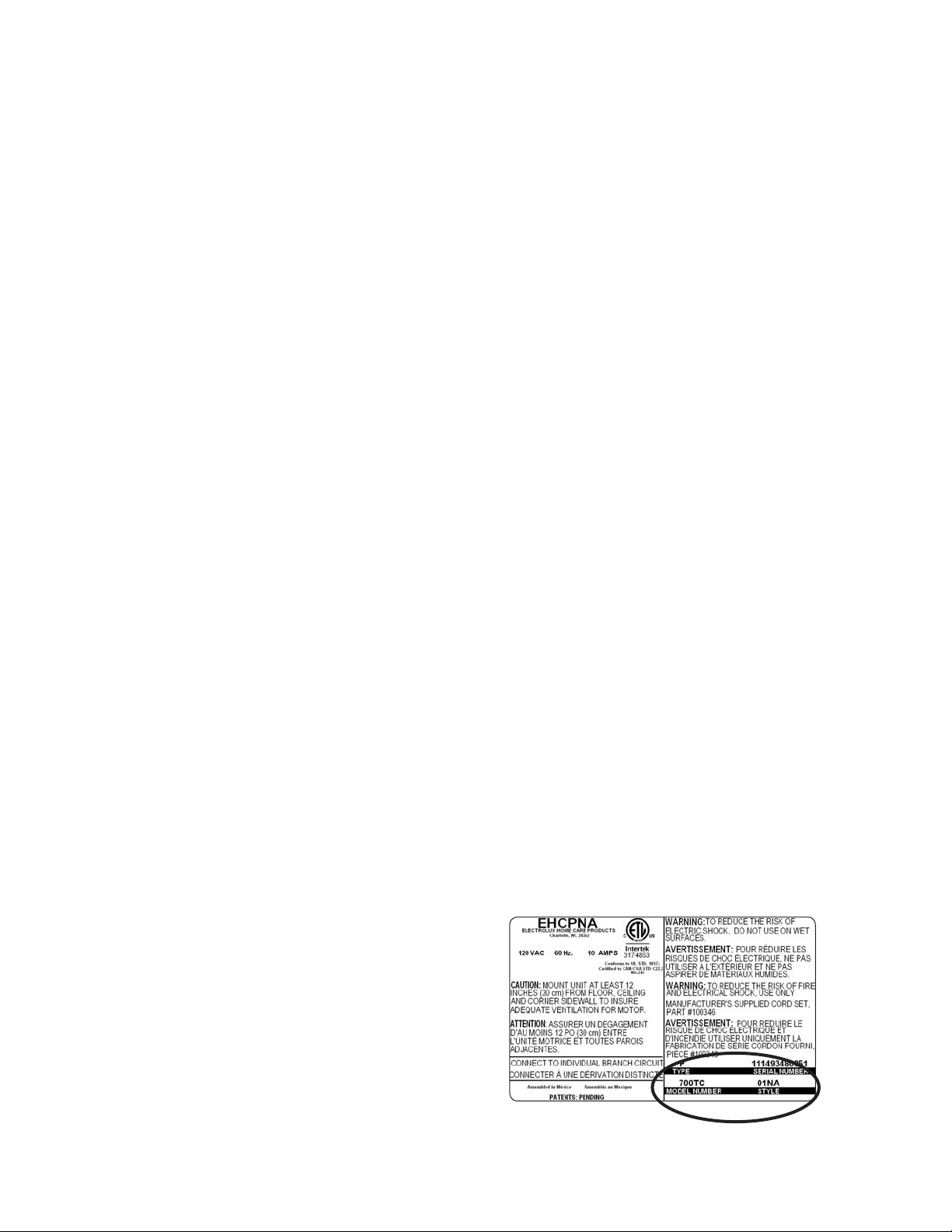
Rating Plate
The style, model and serial numbers are indicated on the
rating plate located on back left side of power unit. For
prompt and complete service information, always refer
to these numbers when inquiring about service (refer to
Figure 1.)
Figure 1.
3
Page 4
GROUNDING INSTRUCTIONS
This vacuum must be grounded (earthed). If it should malfunction or breakdown, grounding (earthing)
provides a path of least resistance for electric current to reduce the risk of electric shock. This vacuum is
equipped with a cord having an equipment-grounding conductor and grounding (earthing) plug. The plug
must be inserted into an appropriate outlet that is properly installed and grounded (earthed) in accordance
with all local codes and ordinances.
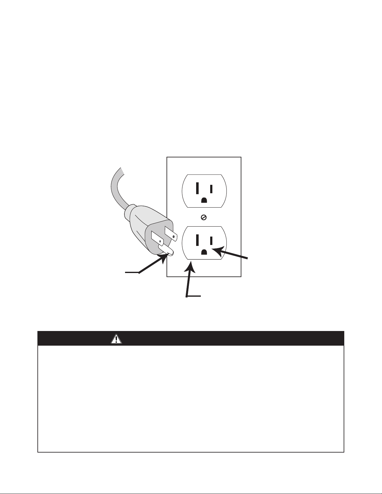
110/115/120V Models
This vacuum is for use on a nominal 110/115/120 volt circuit, and has a grounded plug like the one shown
below. Make sure the appliance is connected to an outlet having the same conguration as the plug. No
adaptor should be used with this vacuum.
Grounded Pin Receptacle
Grounding Pin
Grounded Outlet
WARNING
Improper connections of the equipment-grounding (earthing) conductor can result in risk of electric shock.
Check with qualied electrician or service person if you are in doubt as to whether the outlet is properly
grounded (earthed). Do not modify the plug provided with the appliance. If it will not t the outlet, have the
proper outlet installed by a qualied electrician. This appliance is for use on a nominal 120 volt (see rating
plate for correct voltage) circuit and has a ground (earth) plug that looks like the plug illustrated Make sure
the appliance is connected to an outlet having the same conguration as the plug.
• No adapter should be used with this appliance.
• Do not use an extension cord with this appliance.
• If the power cable is damaged, use only OEM replacement cable.
• Check the power unit on/off button and all inlet valves for operation.
• This power unit is intended for household and commercial use only.
4
Page 5
INSTALLATION
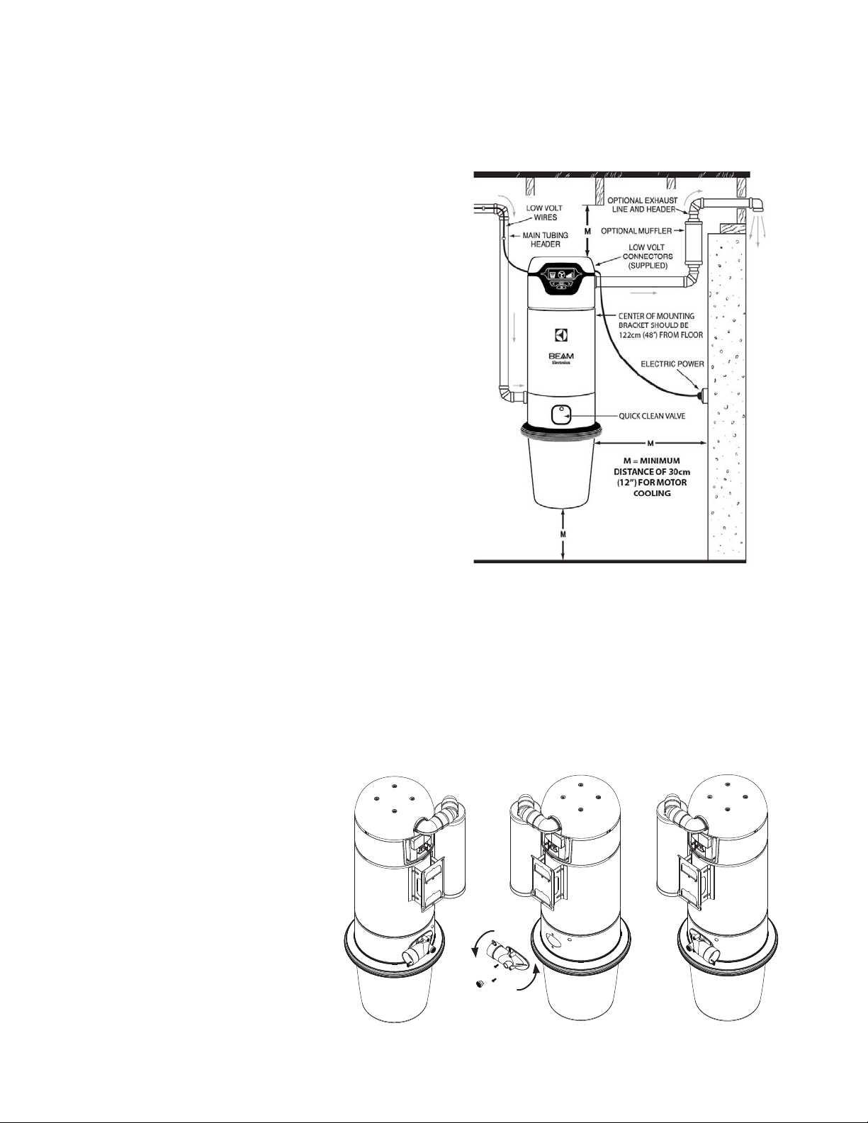
Installation of Power Unit
The power unit hangs on the mounting bracket which is
screwed to the wall. The bottom screws of the mounting
bracket should be about 48” (122 cm) up from the oor
to allow convenient removal of the dirt bucket. For proper
motor cooling, there must be at least 12” (31 cm) between
unit and the ceiling. If mounting on plaster or panel walls,
be sure mounting screws enter studs. If mounting on
concrete wall, drill the wall with a masonry bit and insert the
appropriate wall anchors. Strip the low-voltage wires that
were installed with the main trunk line. (Figure 2)
With optional “Quick Clean” Inlet on the power unit, connect
trunk line wires to wire harness on back of unit before
connecting to the spring loaded connectors on the back
side of the power unit. If you do not have the “Quick Clean”
valve option, simply connect the trunk line wires directly to
the spring loaded connectors on the back side of the power
unit. Connect the main tube line to the tube intake on the
power unit with the connector and clamp provided.
Do not glue the connection to the power unit in case you
wish to remove at a future date. This unit may be vented
outside. Do not exceed a run of over 20 feet off of exhaust,
Do not vent power unit into a wall, ceiling or concealed
space of a building.
NOTE: Power Unit On/Off button is used when unit is not equipped with “Quick Clean” inlet or as an over ride
switch in the event your trunk line wiring becomes damaged. All other inlets operate automatically when hose
end is inserted into inlet valve. The power cable has a three-prong female connector on one end. This connector
must be plugged into the mating connector on the power unit. Plug the other end of the power cable into the
wall electrical outlet.
WIRING: Check local codes, but use not less than #12-2 wires with ground. Plug power unit cord into
appropriate electrical outlet. Be sure line voltage is sufficient to handle 20 amp loads.
Figure 2
Intake Flange
Your power unit has been designed
for either a left or right pipe intake.
This is to give you more exibility
when choosing the location you
wish to hang your power unit. To
change the direction of the intake
ange, you simply remove the two
Torx 20 screws located on the
intake ange and turn the intake
ange 180 degrees. Secure the
intake ange with the same two
Torx 20 screws. (Figure 3)
Figure 3
5
Page 6
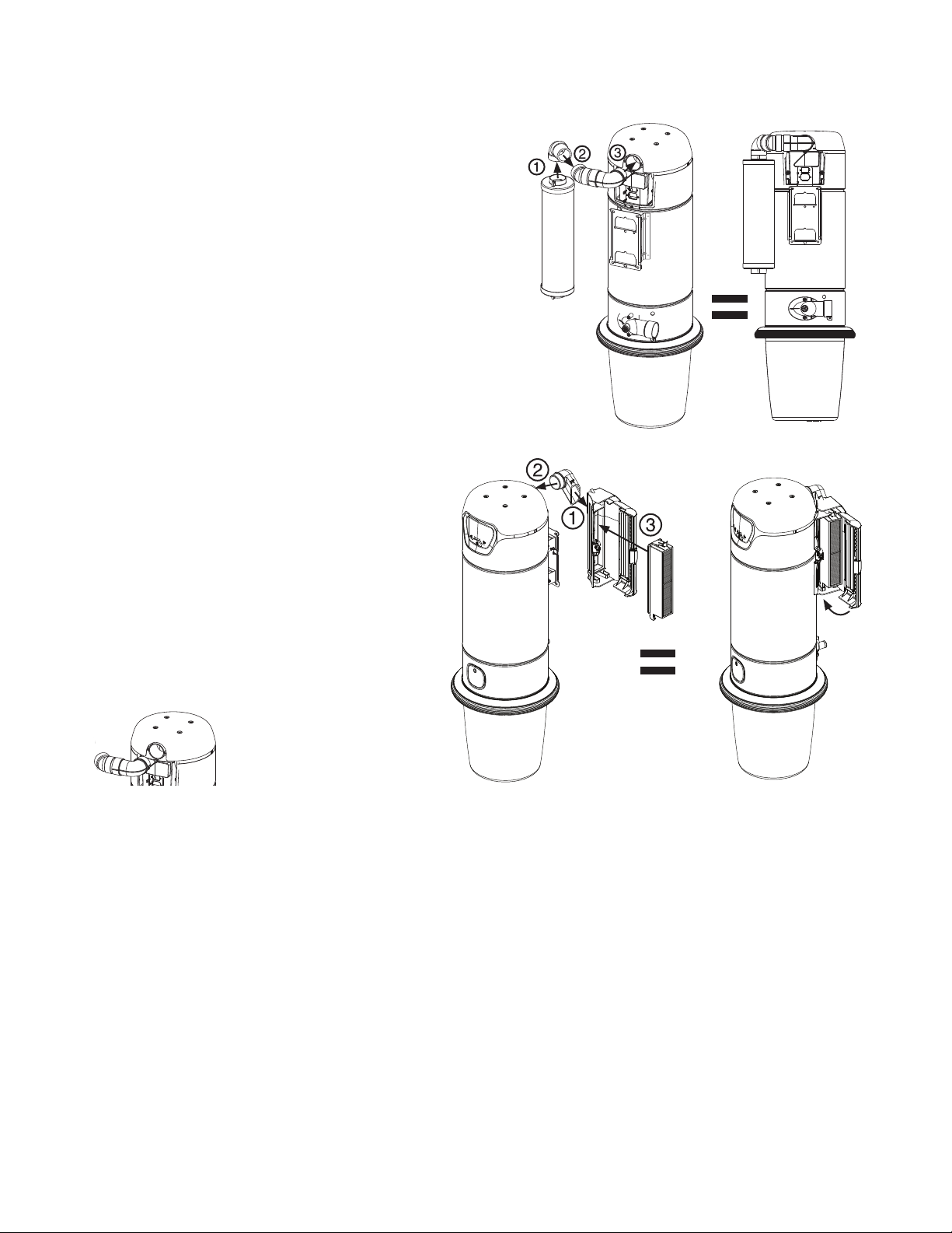
Muffler Installation
The muffler is installed to the exhaust located at the rear
of the power unit using the 3 ttings provided and Torx 20
screws provided. We suggest you install your muffler as
shown, prior to hanging your Power Unit (Although some
modication to this is acceptable), (Figure 4).
NOTE: Do not install muffler on the same side as the
intake ange so as to not interfere with pipe intake. Insert
the 90 degree tting into the muffler and screw into place.
Glue the next two ttings in place before connecting to the
power unit. Use the Torx 20 screws provided to connect
muffler to Power Unit.
NOTE: Do not glue the muffler pipe to the central vacuum
unit.
HEPA Filter Installation (optional)
Use the Torx 20 screws to secure the 90 degree
elbow provided to the HEPA lter. Use screws
to connect HEPA lter to Power Unit. We
recommend you install the HEPA lter before
hanging your Power Unit. (Figure 5a)
Figure 4
NOTE: Do not glue the HEPA lter to the
central vacuum unit.
NOTE: One elbow must be installed if the
muffler or the HEPA lter is not used. (Figure 5b)
Figure 5aFigure 5b
BASIC OPERATION FOR BEAM ALLIANCE POWER UNIT
To operate, simply plug the hose into one of the handy wall inlet valves. The metal ring on the hose cuff will
complete a low-voltage electrical circuit, which in turn activates a relay and turns on the system’s power unit. To
turn off the power unit, simply unplug the hose from the inlet.
Note: When unplugging the hose, it is recommended to hold the inlet door open for a few seconds until the
suction pressure has sufficiently decreased.
For safety purposes, a low-voltage circuit is utilized at the wall inlet. The power unit functions on a standard
110/120-volt circuit. There are optional hoses available with an on/off switch located on the handle.
Note: When using one of these optional hoses, it is important to properly align the hose with the wall inlet when
plugging it in to prevent damage to the unit.
6
Page 7
BASIC OPERATION FOR BEAM ALLIANCE HOSE
The BEAM Alliance hose is designed to work as an integrated system with the BEAM Alliance Power Unit. It
will not work with any other Central Vacuum System. The BEAM Alliance Hose System brings more options to
your ngertips!
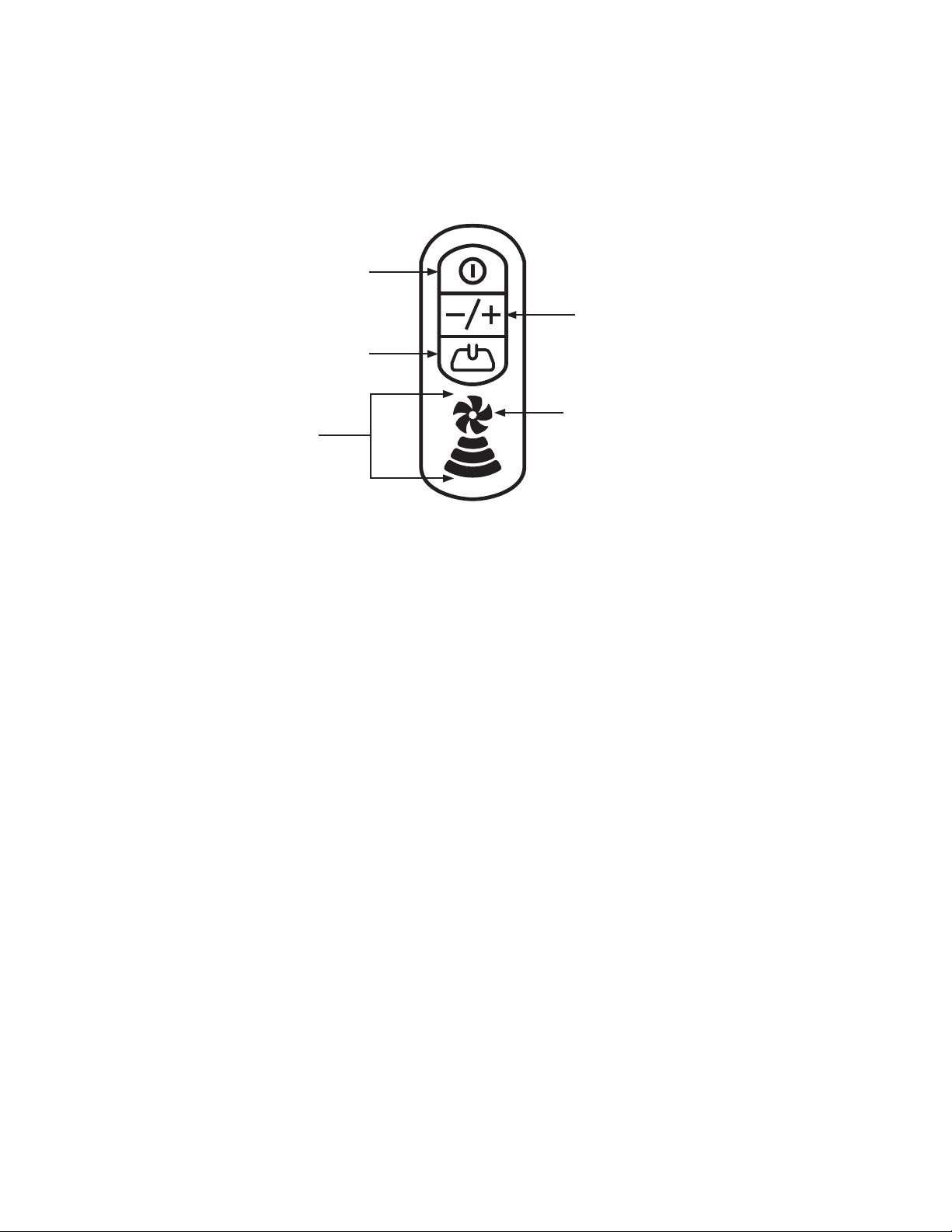
Power Button
Variable Speed
Controls
ON/OFF
Brush Roll
Low
Variable Speed
Indicator
High
System Light:
Blue pulsating light
= system ready/stand-by
Red ashing light
= check power unit
Power Button
The Power button located on Alliance hose handle allows you to conveniently turn the Power Unit off and on at
the handle. For those 110V/24V hoses needed to power an electric powerhead, you will nd a powerhead icon
button conveniently located on the handle that allows you to turn the powerhead off and on.
Variable Speed Control
The BEAM Alliance Hose Handle is equipped with variable speed control allowing you to decrease or increase
the speed of the motor and in effect the end of hose suction. You now can dene how much suction you need
to do the specic job at hand! Decrease suction by pressing the (-) button, and increase suction press the (+)
button. When the system is turned on the suction defaults to highest and so all Variable Speed Indicator bars
will be lit. Decreasing suction decreases the number of indicator bars lit.
System Indicator
When the Alliance hose is connected to an inlet valve the fan blade image on hose handle will pulsate with
a glowing blue light. This conrms communication between the hose handle and power unit. When the fan
blades are solid blue, all systems are GO. When the fan blades are RED, you should empty your bucket or
check for other performance issue. If the fan blades begin FLASHING and are RED, you should turn off your
vacuum immediately. Check over your power unit and if you are unable to diagnose issue, call your local dealer
for service.
CARE AND MAINTENANCE
Your Beam Built-in Vacuum comes with a lifetime limited warranty (see complete warranty details in this
pamphlet). It will give you a lifetime of trouble-free service by following some simple guidelines.
7
Page 8

The BEAM Alliance central vacuum system is equipped with a ow-thru motor and will never need lubrication.
Should you experience any problems with your motor, please contact your local authorized dealer/distributor.
• Power unit can be dusted off with a clean, soft cloth. Caution: do not use liquid cleaners or water as an
electrical shock may occur.
• Do not tamper with power unit. Do not place anything on top of power unit as this could restrict cooling air
to the motor, causing the motor to overheat.
• Do not attempt to pick up anything that will not go through the cleaning tool or hose end. Do not use the
system to pick up construction debris.
• Do not attach anything else to the system’s electrical power source. Be sure that a properly- sized protected
circuit is used for your unit’s electrical requirements. Consult your authorized Beam dealer for the correct
size.
• After removing the hose from the inlet, hold the inlet door open for a few seconds to help clear dirt from the
vacuum tubing and make sure the power unit has been turned off.
• To ensure proper cleaning, use only one inlet at a time.
• If service is ever required, have it performed by your authorized Beam dealer.
Dirt Bucket Cleaning and Maintenance
All of the dirt vacuumed from your home is captured in the dirt bucket located on the bottom of your power unit.
It is important that you remember to empty it on a regular basis to ensure optimal performance. The frequency
required is dependent on many factors in your home (i.e. type of oor coverings, number of people living in the
home and how many pets). A general rule is to empty the dirt receptacle twice a year… in spring and in fall. It
is ideal to empty the dirt bucket when it is half full.
To remove the bucket simply press the Release Ring in
any two opposing positions and pull down. Empty the
debris into a garbage can or bag and reinstall the bucket.
You will hear a click when it is properly reinstalled. It is
important to note that the system will not operate properly
if the bucket is not installed properly (Figure 6).
While the dirt receptacle is off, check that the cloth lter
is free from debris, tears or puncture holes. A clean lter,
free from holes gives your motor maximum protection and
ensures optimal performance.
Figure 6
HEPA Filter Maintenance
It is recommended that you change the HEPA lter annually, (more regularly if you vacuum more than twice a
week).
1. Open HEPA lter door with button located on the side, center
of door.
2. Press down on the tab at top of lter and pull outwards,
(discard lter).
3. Insert New HEPA lter aligning and leading with the two plastic
tabs at bottom of cavity.
4. Snap upright into place.
5. Close HEPA door without force. If the door does not close
easily, remove and reinstall lter (Figure 7).
Figure 7
8
Page 9

Hose Care
For optimum benet, the hose should be used and stored at temperatures above 40˚F (5˚C). Always hang up
the hose when not in use using the hose hanger supplied. If hose should become clogged, insert the wand
end into the utility inlet on the power unit. Seal connection. Turn on the power unit with the manual switch. The
obstruction should be quickly vacuumed out. If, however, the hose remains clogged, insert an electrician’s sh
tape (wire) or garden hose through the hose to remove the obstruction, being careful not to puncture the hose.
Disconnect hose handle from wands before storing. DO NOT store hose in direct sunlight.
TROUBLE-SHOOTING
Automatic Shut-Off
The Alliance Central Vacuum comes equipped with a timed automatic shut off set to automatically turn your
power unit off if your vacuum is left to run for 30 minutes. The shut off is to protect you in the event the vacuum
is inadvertently left on. The shut-off timer is easily reset by turning the power unit on by way of the on/off button
on your hose handle or on the power unit.
The system is also equipped with a thermal protection shut-off to protect the power unit from overheating, In the
event a thermal shut-off occurs, a motor fault icon will be displayed on the screen of the power unit and a red
ashing fan blade will show on the Alliance hose handle. Please allow for the unit to cool for approximately 30
minutes. If the unit does not restart after the 30 minutes, please contact your local authorized dealer/distributor.
Partial Loss of Suction
1. Clean out dirt receptacle. Ensure lter is free from debris, tears and or punctures. If this does not resolves
issue, see step 2.
2. Turn ON vacuum at Power Unit. Check suction at Power Unit. If strong, check the suction at each inlet. If it
is not the same suction at each one, the line may be partially clogged. To locate a clog, compare the suction
at each inlet. First check the inlet closest to the power unit then continue to check each successive inlet until
you locate inlet with loss of suction.. The obstruction will be located between this inlet and the one previously
checked. To remove clog, carefully insert electrician’s sh tape into the inlet and push obstruction through. Or,
If you have a secondary vacuum, you can put vacuum hose into inlet, turn on secondary vacuum and draw out
obstruction. If this fails to remove the clog, call your local authorized dealer/distributor.
Total Loss of Suction (with motor running)
1. Check power, light on screen.
2. If you have good suction at the unit, but no suction in the hose then there is a clog in the pipes or hose. To
remove the clog, refer to step 2 above or call your local authorized dealer/distributor. If obstruction is in your
hose, take your hose to local dealer.
Motor Refuses to Start
1. Check to ensure central vacuum is plugged into an electrical outlet.
2. Check fuses or breakers in your homes electrical panel
3. If power unit has power but your inlets turn on vacuum, the problem will be in your low voltage wiring to the
wall inlets.
4. If you are unable to resolve your issue, call your local authorized dealer/distributor.
9
Page 10
SERVICE INFORMATION
Status OK
Power Nozzle Button
(2G)
Power Button
(Phoenix & 2G)
Left Scroll
Right Scroll
Enter
Attention Needed
Status OK
Status OK
Power Level Button
(2G)
2G-to-Unit Connection
Time
Error Code
Power Nozzle Button
(2G)
Power ON/Power Level
(2G)
Performance Level
Bucket Level
Motor Running
Screensaver
Call for Service
Power Nozzle Button
(2G)
Power ON/Power Level
(2G)
Performance Level
Power Nozzle Button
(2G)
Power ON/Power Level
(2G)
Status OK
2G-to-Unit Connection
Time
Error Code
Power Nozzle Button
(2G)
Power ON/Power Level
(2G)
Performance Level
Bucket Level
Status OK
2G-to-Unit Connection
Time
Error Code
Power Nozzle Button
(2G)
Power ON/Power Level
(2G)
Performance Level
Bucket Level
Status OK
Time
Error Code
Power Nozzle Button
(2G)
Power ON/Power Level
(2G)
Performance Level
Bucket Level
Motor Running
Call for Service
Power Nozzle Button
(2G)
Power ON/Power Level
(2G)
Performance Level
Bucket Level
Motor Running
Screensaver
(2G)
(2G)
(2G)
Status OK
2G-to-Unit Connection
Time
Error Code
Power Nozzle Button
(2G)
Power ON/Power Level
(2G)
Performance Level
Bucket Level
Call for Service
Power Nozzle Button
(2G)
The instructions in this booklet serve as a guide for routine operation and maintenance. For further
Information contact your local authorized dealer/distributor
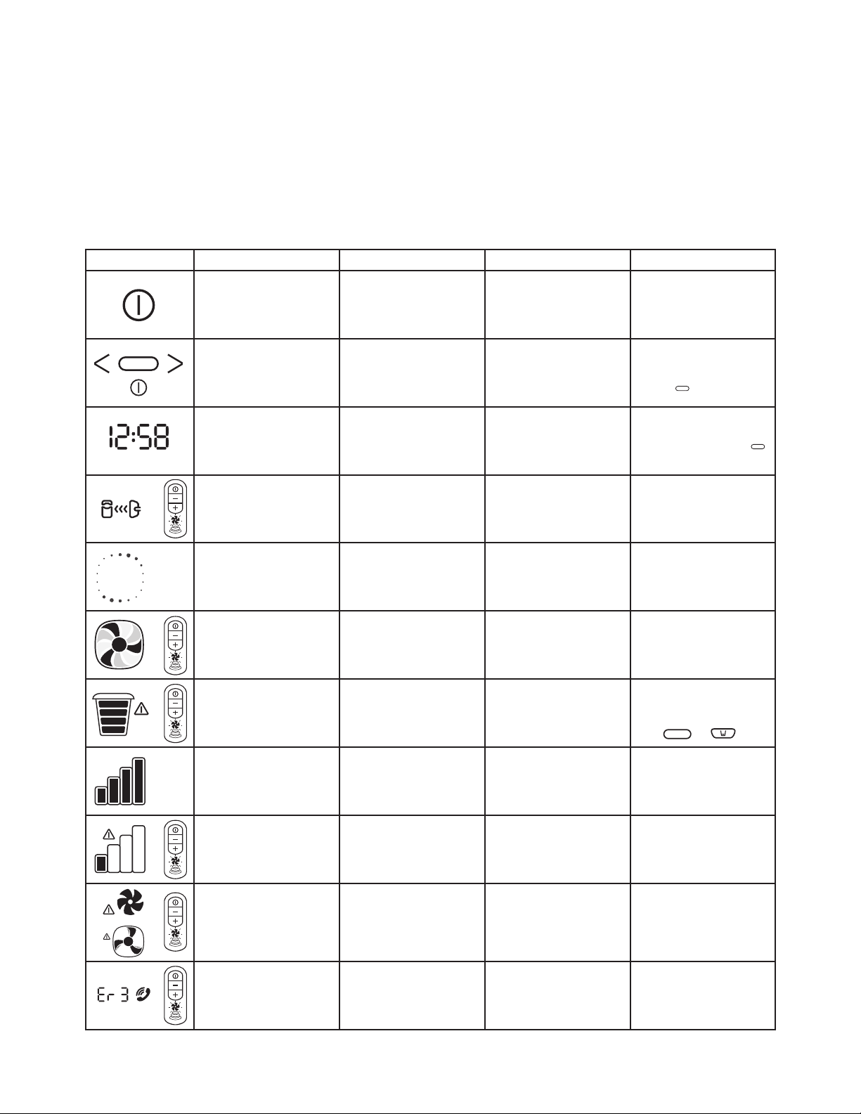
BEAM ALLIANCE LED/LCD ICON CHART
SYMBOL DESCRIPTION AVAILABILITY MEANING ACTION REQUIRED
ON/OFF Button Standard Turns power unit on or off None
10
or
Navigation Buttons On select models These buttons are located below
Clock On select models A digital clock is located on the top
Communication Link On select models The communication link icon
Screen Saver On select models When the power unit wakes from
Variable Speed Indicator On select models When the power unit is on, the
Empty Bucket Indicator On select models The empty bucket indicator is
Performance Bars On select models 3 - 4 bars indicate the system is
Flashing Performance Bars Alert On select models When 2 bars or less are illuminated,
Motor Fault Indicators Standard Indicates a system fault or
Error Codes On select models Error codes dened:
the display screen. Use to modify
time or reset empty bucket indicator
left corner of the display screen of
the power unit
appears at the top of the power
when the hose connection into the
inlet valve is complete and the hose
handle is communicating with the
sleep mode, the screen saver icon
will appear for 2-3 seconds before
timed to remind you to empty your
communicate with the hose handle
exceptionally restricted. The power
unit will communicate to the hose
handle and ashing red fan blades
exceeded; 2) Electronics problem;
3) Power surges; 4) Motor failure; 5)
power unit
disappearing and other icons will
spin relative to the speed/suction
appear
fan blades on the screen will
indicated on the hose handle
dirt bucket. The power unit will
signalling fan blades to ash red
performing at the optimum level.
Performance levels will change
depending on the variable speed
settings and during the use of
specialty attachments
the airow of your power unit is
will display
malfunction. This symbol may
occur due to one of the following:
1) Maximum system run time
Mechanical failure
ER 1: Under current
ER 2: Over current short
ER 3: 30-minute time out
ER 4: Over current long
ER 5: Line error or off current
Scroll through using Left ( < ) or
Right ( > ) buttons to appropriate
icon. When the appropriate
selection is highlighted, hold the
Enter ( ) button down for 5
seconds
You can choose from either a 12
or 24 hour clock. To set time, use
the (<) and (>) buttons to arrive at
the correct time. Press Enter ( )
when your selections are complete
None
None
None
Empty dirt bucket and reset the
system by pushing one of the two
reset buttons and holding for 5
seconds
or
Check for blockage if performance
bars uctuate under normal
vacuuming conditions
Check to ensure the dirt bucket
is not overloaded. Check for
blockages in the system. Check for
motor wear (contact an authorized
service technician)
Turn on and off the power unit. This
may reset the system. If this fails,
unplug the power unit and call an
authorized technician
Turn off and unplug power unit
and call an authorized technician.
For further detail on error codes,
contact your authorized service
dealer
Page 11

WARRANTY
Lifetime Limited Warranty
Electrolux Central Vacuum Systems is protected by a limited lifetime warranty. This warranty is valid from the
date of purchase, for as long as you are the original owner, and the system remains at its original place of
installation.
• Limited lifetime warranty on metal body and self cleaning lter.
• Motors, electrical components and dirt receptacle in BEAM Alliance power units are warranted for 15 years.
• BEAM Alliance cleaning sets carry a 5 year warranty.
• Labor on all warranted items is covered for 1 year.
This warranty does not apply to consumable items requiring normal replacement such as belts, replacement
lter bags and lights.
THIS IS THE SOLE AND EXCLUSIVE WARRANTY OF ELECTROLUX CENTRAL VACUUM SYSTEMS.
IMPLIED WARRANTIES, INCLUDING IMPLIED WARRANTIES OF MERCHANTABILITY OR FITNESS FOR A
PARTICULAR PURPOSE ARE LIMITED IN DURATION OF LIMITED WARRANTY PERIOD.
Should any defect in material or workmanship appear within the time of the above warranty, the selling BEAM
Dealer should be contacted. The Dealer shall repair or replace (at BEAM’s sole option), or credit, such part or
parts in accordance with the applicable warranty period stated above. BEAM shall not be responsible for such
service unless provided by an authorized BEAM Dealer utilizing authentic BEAM replacement parts.
This warranty does not apply to loss or damage resulting from (at BEAM’s sole option) normal wear and tear,
commercial use, vacuum of drywall dust, neglect, abuse acts of God, accidents, improper installation, improper
modication or alteration, improper use and operation or failure to provide proper maintenance.
Some States or Provinces do not allow exclusion of warranties or limitations of damages, so the above
limitations and exclusions may not apply to you. This warranty gives you specic legal rights. You may have
additional rights, which vary from State to State, or Province to Province. This limited warranty applies to USA
and Canada installations only. For specic warranty information for your Country, consult your authorized Beam
Dealer.
Other warranties apply to other parts of this equipment and optional accessories. Please contact the material
accompanying the individual items.
BEAM SHALL NOT BE RESPONIABLE FOR ANY CONSEQUENTIAL, INCIDENTAL, OR SPECIAL DAMAGES
ARISING FROM THE USE OF THIS SYSTEM.
Keep all payment records (bill of sale/delivery slip). The date on these records establishes the warranty period.
Should warranty service be required, you must show proof of purchase. If proof of purchase cannot be supplied,
the warranty period will be determined from the date of manufacture of the product.
In the event of a product recall, register your products at www.beam.com.
United States
10200 David Taylor Drive
Charlotte, NC 28262
1-800-369-2326
Canada
5855 Terry Fox Way
Mississauga, ON L5V 3E4
1-800-282-2886
11
Page 12

12
Sold and serviced by:
© 2013 Electrolux Home Care Products Ltd. #87238-R2
Page 13

BEAM Alliance
Manuel d’utilisation
Page 14

IMPORTANTES DIRECTIVES DE SÉCURITÉ
Lors de l’utilisation d’un appareil électronique, des précautions de base devraient toujours être prises, incluant celles
indiquées ci-dessous.
LISEZ TOUTES LES DIRECTIVES AVANT D’UTILISER CET ASPIRATEUR CENTRAL.
AVERTISSEMENT
An de réduire les risques d’incendie, de décharges électriques ou blessures :
• Cet aspirateur est conçu pour le ramassage de débris secs seulement. Ne l’utilisez pas sur des surfaces
mouillées ou pour ramasser des liquides, des débris chauds ou des matières inammables, lesquelles peuvent
endommager l’aspirateur.
• Tenez le l loin des surfaces chauffées.
• Ne permettez pas que l’aspirateur soit utilisé comme un jouet. Une surveillance étroite est nécessaire lorsque
cet aspirateur est utilisé par des enfants ou près d’eux.
• N’utilisez cet aspirateur que pour l’usage pour lequel il a été conçu et tel que décrit dans ce manuel. (L’utilisation
d’accessoires non recommandés par le fabricant peut être une cause d’incendie, de décharge électrique, de
blessures ou de dommages aux composantes du système.)
• Branchez-le seulement dans une prise de courant correctement mise à la terre. Voir les instructions de mise à la
terre.
• Installez l’unité motrice à au moins 30 cm (12’’) du plancher, du plafond et des murs adjacents pour permettre
une ventilation adéquate du moteur.
• N’utilisez pas cet aspirateur si le cordon ou la che sont endommagés, s’il ne fonctionne pas correctement ou s’il
a été échappé ou endommagé. Apportez-le à un détaillant/distributeur autorisé pour réparation.
• Ne débranchez pas la che en tirant sur le cordon. Pour débrancher de la prise de courant, prenez et tirez la
che, et non le cordon.
• N’insérez aucun objet dans les prises d’aspiration. N’utilisez pas l’appareil si une des prises d’aspiration est
obstruée. Gardez les prises d’aspiration exemptes de toute accumulation de poussière, charpie, cheveux ou
toutes autres choses qui peut réduire le débit d’air/d’aspiration. La réduction du débit d’air entraînera une
surchauffe du moteur.
• Cet aspirateur crée une succion. Gardez les vêtements amples, les cheveux, le visage, les doigts et toutes les
autres parties du corps loin de toutes les prises d’aspiration.
• Ne faites jamais fonctionner cet appareil si le sac à poussière et/ou le ltre ne sont pas en place.
• Fermez toutes les commandes avant de débrancher.
• Ne manipulez pas la che, le cordon ou l’unité motrice avec des mains mouillées.
• Redoublez de prudence lorsque vous nettoyez les escaliers.
• Ne placez pas l’unité motrice dans un endroit où la température est élevée ou dans un endroit où il sera difficile
d’y accéder comme un comble ou un vide sanitaire.
• N’utilisez pas de rallonges ni de prises électriques dont l’intensité de courant admissible n’est pas adéquate.
• Ne ramassez rien qui vient de brûler ou dont une fumée s’échappe, comme des cigarettes, des allumettes ou
des cendres chaudes.
• N’utilisez pas cet appareil sur des surfaces mouillées.
• N’aspirez pas de poussière de placoplâtre ou de farine parce que cela peut endommager votre aspirateur.
• Cet appareil n’est pas destiné à être utilisé par des personnes (incluant les enfants) ayant des capacités
physiques, sensorielles ou mentales réduites, ou manquant d’expérience ou de connaissances, à moins qu’une
personne responsable de leur sécurité ne leur ait donné des directives sur l’utilisation de l’appareil ou ne les
supervise.
• Si le cordon d’alimentation est endommagé, il doit être remplacé par un cordon spécique que vous trouverez
chez le détaillant ou le distributeur autorisé local.
• Gardez votre aire de travail bien éclairé.
• Débranchez les appareils électriques avant de les nettoyer.
• N’utilisez pas cet aspirateur pour ramasser des liquides inammables ou combustibles, comme de l’essence, ou
pour nettoyer des endroits où des produits de ce genre peuvent être présents.
14
CONSERVEZ CES DIRECTIVES
Page 15

Cher client Beam;
Félicitations pour votre nouvel aspirateur central BEAM Alliance! Vous venez juste d’acheter l’aspirateur central le plus
novateur et le plus intuitif de Beam. Merci de votre appui. Pour proter au maximum de tous les avantages, veuillez lire
ce manuel d’instructions avant d’installer et d’utiliser votre aspirateur central. Nous vous recommandons de conserver ce
manuel d’instructions pour référence ultérieure.
Pour acheter des accessoires et des services d’installation ou vous informer sur ceux-ci, veuillez communiquer avec votre
détaillant local ou visitez notre site Web à www.beam.com.
Nous vous recommandons d’enregistrer votre aspirateur central en ligne à www.beam.com.
Pour plus de commodité, inscrivez ci-dessous le numéro de modèle et le numéro de série qui se trouvent sur votre unité
motrice, ainsi que la date d’achat. Vous trouverez ces numéros sur la plaque signalétique apposée sur la partie supérieure
arrière de l’unité motrice.
Numéro de modèle _______________________
Numéro de série _______________________
Date d’achat _______________________
Ouverture de l’emballage
Votre aspirateur central ainsi que la quincaillerie et les accessoires qui l’accompagnent sont soigneusement emballés dans
une boîte de carton conçue pour les protéger contre les dommages pouvant survenir durant le transport. Vous trouverez les
pièces nécessaires pour suspendre votre aspirateur central dans la cuve à poussière.
IInstallation de votre aspirateur central
Si vous planiez installer vous-même votre aspirateur central, vous trouverez si notre site www.beam.com un excellent
guide d’installation ainsi qu’une vidéo d’installation. Si vous désirez que l’installation de votre aspirateur central soit faite par
un professionnel, communiquez avec votre détaillant local ou téléphonez au 1-800-369-2326 (pour les États-Unis) ou au
1-800-282-2886 (pour le Canada). Nous serons heureux de vous diriger vers un installateur professionnel de votre région.
INFORMATION GÉNÉRALE
Ce système central d’aspiration est conçu pour le ramassage des débris domestiques secs et n’est pas conçu
pour ramasser des liquides. Évitez de ramasser des objets durs, coupants ou pointus avec le système pour ne
pas endommager ou obstruer le boyau et les tuyaux en plastique. Ce système central est destiné à un usage
domestique seulement.
Information concernant l’entretien/réparation
Les directives contenues dans ce livret servent de guide pour l’entretien de routine. Pour de plus amples
informations, communiquez avec votre détaillant/distributeur autorisé local.
Plaque signalétique
Le style ainsi que les numéros de modèle et de série
sont indiqués sur la plaque signalétique qui se trouve du
côté gauche à l’arrière de l’unité motrice. Pour obtenir des
informations de service après-vente rapides et complètes,
donnez toujours ces numéros lors des appels de service
après-vente (voir la gure 1.)
Figure 1.
15
Page 16

INSTRUCTIONS DE MISE À LA TERRE
Cet aspirateur doit être mis à la terre. En cas de mauvais fonctionnement ou de panne, la mise à la terre
procure une voie de moindre résistance pour le courant électrique an de réduire le risque de décharge
électrique. Cet aspirateur est équipé d’un cordon électrique doté d’une che avec conducteur de mise à la terre.
La che doit être insérée dans une prise électrique appropriée qui est correctement installée et mise à la terre
conformément aux codes et règlement locaux.
Modèles 110/115/120 V
Cet aspirateur doit être utilisé sur un circuit nominal de 110/115/120 volts et est doté d’une che de mise à la
terre semblable à celle montrée ci-dessus. Assurez-vous que l’appareil est branché dans une prise électrique
ayant la même conguration que la che. Aucun adaptateur ne doit être utilisé avec cet aspirateur.
Alvéole de la broche de mise à la terre
Broche de mise à la terre
Prise de courant mise à la terre
AVERTISSEMENT
Des branchements inadéquats de l’équipement de mise à la terre entraînent des risques de décharges électriques. Si
vous n’êtes pas certain que la prise soit convenablement mise à la terre, consultez un électricien ou un technicien de
service qualié. Ne modiez pas la che fournie avec l’appareil. Si elle n’adapte pas à la prise de courant, faites installer
une prise de courant adéquate par un électricien qualié. Cet appareil est conçu pour un circuit nominal de 120 volts
(consultez la plaque signalétique pour savoir quelle est la tension appropriée) et est doté d’une che avec mise à la terre
qui ressemble à celle montré ci-dessous. Assurez-vous que l’appareil est branché dans une prise de courant ayant la
même conguration que la che.
• Aucun adaptateur ne doit être utilisé avec cet appareil.
• N’utilisez pas de l de rallonge avec cet appareil.
• Si le câble d’alimentation est endommagé, utilisez seulement un câble de rechange d’origine.
• Assurez-vous que le bouton marche/arrêt de l’unité motrice et que toutes les prises d’admission d’air fonctionnent
bien.
• Cette unité motrice a été conçue pour un usage domestique ou commercial seulement.
16
Page 17

INSTALLATION
Installation de l’unité motrice
L’unité motrice doit être suspendue à un support de xation vissé au
mur. Les vis allant au bas du support de xation doivent être vissées
à environ 122 cm (48’’) au-dessus du plancher an de pouvoir
enlever aisément la cuve à poussière. Un espace d’au moins 31 cm
(12’’) doit également être laissé entre l’unité motrice et le plafond an
de permettre un refroidissement adéquat du moteur. Si l’installation
du support de xation se fait sur des murs de plâtre ou des panneaux
muraux, assurez-vous que les vis soient insérées dans les montants
du mur. Si l’installation se fait sur un mur de béton, percez le
mur avec un foret à maçonnerie et insérez les ancrages muraux
appropriés. Dénudez les ls à basse tension qui ont été installés
avec la ligne de tuyauterie principale (gure 2).
Fils à basse
tension
Collecteur de la
ligne de tuyauterie
principale
Ligne et collecteur
d’évacuation
optionnels
Silencieux optionnel
Connecteurs à
basse tension
(fournis)
Le centre du support de
montage doit être à 122 cm
(48’’) du plancher
Prise de courant murale
Prise d’aspiration
Quick Clean
Si l’unité motrice est dotée de la prise d’aspiration optionnelle
« Quick Clean » pour nettoyage rapide, reliez les ls de la ligne
principale au faisceau de ls électriques qui se trouvent à l’arrière de
M = Distance minimum
de 30 cm (12’’)
pour permettre le
refroidissement du moteur
l’unité motrice avant de les relier aux connecteurs à ressort à l’arrière
de l’unité motrice. Si vous n’avez pas la prise d’aspiration optionnelle
« Quick Clean » pour nettoyage rapide, vous n’avez qu’à relier
directement les ls de la ligne principale aux connecteurs à ressort
qui se trouvent à l’arrière de l’unité motrice. Raccordez ensuite la
ligne de tuyauterie principale au tuyau de la prise d’admission d’air à
Figure 2
l’aide du raccord et du collier de serrage fournis.
Ne collez pas le raccord à l’unité motrice au cas où vous voudriez enlever celle-ci ultérieurement. Cette unité motrice peut
avoir un système d’évacuation à l’extérieur; le parcours d’évacuation ne doit toutefois pas être de plus de 6,1 m (20’).
La sortie du système d’évacuation ne doit pas donner à l’intérieur d’un mur, d’un plafond ou d’un espace dissimulé d’un
bâtiment.
NOTE : Le bouton marche/arrêt placé sur l’unité motrice sert uniquement lorsque l’unité motrice n’est pas dotée d’une prise
d’aspiration « Quick Clean » ou est utilisé comme interrupteur prioritaire si le lage de la ligne principale est endommagé.
Toutes les autres prises d’aspiration fonctionnent automatiquement lorsque l’extrémité du boyau y est insérée. Le cordon
d’alimentation a une che femelle tripolaire à une des extrémités. Cette che doit être branchée dans le connecteur
homologue de l’unité motrice. Branchez l’autre extrémité du cordon d’alimentation dans la prise de courant murale.
FILAGE : Vériez les codes locaux, mais n’utilisez pas de lage moindre de #12-2 avec mise à la terre. Branchez le cordon
d’alimentation de l’unité motrice dans une prise de courant appropriée. Assurez-vous que le circuit électrique peut supporter
une charge de 20 ampères.
Bride d’admission d’air
Votre unité motrice a été conçue
pour recevoir un tuyau d’admission
d’air gauche ou droit. Ceci a pour
but de vous donner plus de exibilité
pour choisir l’emplacement désiré
pour suspendre votre unité motrice.
Pour changer la direction de la bride
d’admission d’air, vous n’avez qu’à
retirer les deux vis Torx 20 qui se
trouvent sur la bride d’admission d’air,
puis tournez la bride d’admission d’air
à 180 degrés. Fixez fermement la
bride d’admission d’air avec les deux
mêmes vis Torx 20. (Figure 3)
Figure 3
17
Page 18

Installation du silencieux
Le silencieux s’installe au niveau de l’orice d’évacuation qui
se trouve à l’arrière de l’unité motrice en utilisant les 3 raccords
fournis et les vis Torx 20 fournies. Nous vous suggérons d’installer
le silencieux, tel qu’indiqué, avant de suspendre votre unité
motrice (bien que certains modications à cette méthode soient
acceptables). (Figure 4)
NOTE : Installez le silencieux du côté opposé à la bride
d’admission an qu’il ne nuise pas au raccordement de la
tuyauterie d’admission. Insérez le raccord à 90 degrés dans le
silencieux et vissez-le. Placez les deux autres raccords et collezles avant de les raccorder à l’unité motrice. Utilisez les vis Torx 20
fournies pour raccorder le silencieux à l’unité motrice.
NOTE : Ne collez pas le tuyau du silencieux à l’unité motrice de
l’aspirateur central.
Installation du ltre HEPA
(optionnelle)
Utilisez les vis Torx 20 pour xer fermement le coude
à 90 degrés fournis au ltre HEPA. Utilisez des vis
pour xer le ltre HEPA sur l’unité motrice. Nous vous
recommandons d’installer le ltre HEPA avant de
suspendre l’unité motrice. (Figure 5)
Figure 4
NOTE : Ne collez pas le ltre HEPA à l’unité motrice
de l’aspirateur central.
NOTE : Un coude large doit être installé si le
silencieux ou le ltre HEPA n’est pas utilisé.
(Figure 5b)
Figure 5
Figure 5b
RÈGLES D’UTILISATION DE BASE POUR L’UNITÉ MOTRICE
BEAM ALLIANCE
Pour faire démarrer l’unité motrice, vous n’avez qu’à brancher le boyau dans l’une des pratiques prises d’aspiration murale.
L’anneau métallique sur l’embout du boyau complétera le circuit électrique à basse tension, ce qui activera un relais et fera
démarrer l’unité motrice du système. Pour arrêter l’unité motrice, il suffit de débrancher le boyau de la prise d’aspiration
murale.
Note : Lorsque vous débranchez le boyau, il est recommandé de tenir le clapet ouvert pendant quelques secondes, jusqu’à
ce que la pression d’aspiration ait suffisamment diminué.
Pour des raisons de sécurité, un circuit à basse tension est utilisé au niveau des prises d’aspiration murales. L’unité motrice
fonctionne sur un circuit électrique standard de 110/120 volts. Des boyaux dotés d’un interrupteur sur la poignée sont offerts
en option.
18
Note : Si vous utilisez un des ces boyaux optionnels, il est important de bien aligner le boyau avec la prise d’aspiration
Page 19

murale lorsque vous l’y branchez pour éviter d’endommager le système.
RÈGLES D’UTILISATION DE BASE POUR LE BOYAU BEAM
ALLIANCE
Le boyau BEAM Alliance est conçu pour fonctionner comme un système intégré avec l’unité motrice BEAM Alliance. Il ne
fonctionnera pas avec un autre système central d’aspiration. Le boyau BEAM Alliance offre plusieurs options qui se trouvent
au bout de vos doigts!
Bouton marche/arrêt
Interrupteur pour le
rouleau-brosseur
Indicateur de
vitesse variable
Basse
Élevée
Commande de
vitesse variable
Indicateur lumineux du système
Lumière pulsatoire bleue =
système prêt/en attente
Lumière clignotante rouge =
unité motrice à vérier
Bouton marche/arrêt
Le bouton marche/arrêt, placé sur la poignée du boyau Alliance, vous permet de mettre en marche et d’arrêter aisément
l’unité motrice. Sur les boyaux de 110/24 V, nécessaires pour utiliser une brosse motorisée électrique, il y a également un
bouton icône, placé de façon pratique sur la poignée du boyau, qui vous permet de mettre en marche et d’arrêter la brosse
électrique.
Commande de vitesse variable
La poignée du boyau Alliance est également dotée d’une commande de vitesse variable qui vous permet de diminuer ou
d’augmenter la vitesse du moteur et, par conséquent, la puissance d’aspiration au bout du boyau. Vous pouvez maintenant
dénir la puissance d’aspiration dont vous avez besoin pour accomplir une tâche spécique! Pour diminuer la puissance
d’aspiration, appuyez sur le bouton (-) et pour l’augmenter, appuyez sur le bouton (+). Lorsque le système est mis en
marche, il offre, par défaut la puissance d’aspiration la plus élevée et, par conséquent, toutes les barres de l’indicateur de
vitesse variable seront allumées. Si vous diminuez la puissance d’aspiration, le nombre de barres allumées de l’indicateur
diminuera.
Indicateur lumineux du système
Lorsque le boyau Alliance est branché dans une prise d’aspiration, l’icône « pales de ventilateur » affichera une lumière
pulsatoire bleue. Cela conrme que la communication est établie entre la poignée du boyau et l’unité motrice. Lorsque
les pales de ventilateur sont d’un bleu constant, cela signie que tous les systèmes sont PRÊTS. Lorsque les pales de
ventilateur sont ROUGES, cela signie que vous devez vider la cuve à poussière ou vérier s’il y a un autre problème
de rendement. Si les pales de ventilateur commencent à CLIGNOTER et qu’elles sont ROUGES, vous devez arrêter
immédiatement l’aspirateur. Vériez ce qui est affiché sur votre unité motrice et si vous êtes incapable de diagnostiquer le
problème, faites un appel de service auprès de votre détaillant local.
19
Page 20

ENTRETIEN ET MAINTENANCE
Votre aspirateur central BEAM est couvert par une garantie à vie limitée (voir les détails complets de la garantie dans ce
manuel). En suivant les quelques directives simples qui suivent, vous proterez des avantages de celui-ci sans problèmes
et durant de très nombreuses années.
Le système central d’aspiration BEAM Alliance est équipé d’un moteur à circulation d’air directe et il n’aura jamais besoin
de lubrication. Si vous avez des problèmes avec votre moteur, veuillez communiquer avec votre détaillant/distributeur
autorisé local.
• L’unité motrice doit être époussetée avec un chiffon doux propre. Avertissement : n’utilisez pas de nettoyants
liquides ou d’eau parce que cela peut causer une décharge électrique.
• Ne manipulez pas l’unité motrice. Ne mettez rien sur le dessus de l’unité motrice parce que cela pourrait nuire au
refroidissement du moteur et, de ce fait, entraîner une surchauffe du moteur.
• N’essayez pas d’aspirer quelque chose qui ne passera pas à travers l’accessoire de nettoyage ou l’embout du boyau.
N’utilisez pas ce système d’aspiration pour ramasser des débris de construction.
• Ne reliez rien d’autre à la source d’alimentation électrique du système. Assurez-vous qu’un circuit protégé d’un calibre
adéquat est utilisé pour répondre aux besoins électriques de votre unité motrice. Consultez votre détaillant autorisé
Beam pour savoir quel est le calibre requis.
• Après avoir retiré le boyau de la prise d’aspiration, tenez le clapet de la prise ouvert pendant quelques secondes pour
aider à dégager les tuyaux de la saleté qui s’y trouve et assurez-vous que l’unité motrice est bien arrêtée.
• Pour un nettoyage adéquat, n’utilisez qu’une prise d’aspiration à la fois.
• Si jamais votre système a besoin d’entretien ou de
réparation, assurez-vous que le service sera effectué par
votre détaillant autorisé BEAM.
Nettoyage et entretien de la cuve à poussière
Toutes les saletés et poussières aspirées sont emprisonnées
dans la cuve à poussière placée au bas de votre unité motrice.
Il est important de ne pas oublier de la vider sur une base
régulière pour que votre système offre une performance
optimale. La fréquence requise dépend de plusieurs facteurs (c.à-d. le type de revêtements de sol, le nombre de personnes et
d’animaux de compagnie qui vivent dans votre maison). La règle
générale est de vider la cuve à poussière deux fois par année...
au printemps et à l’automne. Par contre, l’idéal est de vider la cuve à poussière lorsqu’elle est à moitié pleine.
Pour retirer la cuve, appuyez simplement sur la bague de déverrouillage en deux points opposés et tirez vers le bas.
Videz les débris dans une poubelle ou un sac et réinstallez la cuve. Vous entendrez un clic lorsqu’elle sera correctement
réinstallée. Il est important de noter que le système ne fonctionnera pas correctement si la cuve n’est pas installée
correctement. (Figure 6)
Pendant que la cuve à poussière est retirée, assurez-vous que le ltre en toile est exempt de débris, de déchirures ou de
perforations. Un ltre propre, exempt de trous, protège le moteur de votre unité motrice de façon maximale et permet à votre
système d’avoir une performance optimale.
Figure 6
Entretien du ltre HEPA
Il est recommandé de changer le ltre HEPA sur une base annuelle (plus
fréquemment si vous passez l’aspirateur plus de deux fois par semaine).
1. Ouvrez la porte du ltre HEPA en appuyant sur le bouton placé sur le
côté au centre de la porte.
2. Appuyez sur la languette qui se trouve au haut du ltre et tirez le ltre
vers l’extérieur (jetez le ltre).
3. Insérez le nouveau ltre HEPA en l’alignant avec les deux languettes
de plastique au bas de la cavité.
Figure 7
20
Page 21

4. Enclenchez-le en position verticale.
5. Fermez doucement la porte du ltre HEPA. Si la porte ne se ferme pas facilement, retirez le ltre et réinstallez-le.
(Figure 7)
Entretien du boyau
Pour que le boyau offre un rendement optimal, il doit être utilisé et rangé à des températures supérieures à 5 ˚C (40˚F).
Suspendez toujours le boyau sur le support à boyau fourni lorsqu’il n’est pas utilisé. Si le boyau est obstrué, insérez
l’extrémité du tube dans la prise d’aspiration utilitaire qui se trouve sur l’unité motrice. Scellez l’ouverture de la prise.
Démarrez l’unité motrice en appuyant sur l’interrupteur manuel. Ce qui crée l’obstruction devrait être rapidement aspiré.
Toutefois, si le boyau demeure obstrué, insérez un ruban de tirage ou un boyau d’arrosage dans le boyau pour retirer ce qui
obstrue le boyau, en prenant soin de ne pas percer le boyau. Retirez les tubes du boyau avant de ranger celui-ci. NE rangez
PAS le boyau à la lumière directe du soleil.
DÉPANNAGE
Arrêt automatique
L’aspirateur central Alliance est équipé d’un dispositif d’arrêt automatique qui arrête automatiquement l’unité motrice
après 30 minutes. Ce dispositif d’arrêt vise à vous protéger si votre aspirateur est laissé en fonction par inadvertance. La
minuterie peut facilement être remise à zéro en appuyant sur le bouton marche/arrêt qui se trouve sur la poignée du boyau
ou sur celui qui se trouve sur l’unité motrice.
Le système est également équipé d’une protection thermique d’arrêt pour protéger l’unité motrice contre la surchauffe. En
cas d’arrêt thermique, un icône de défaillance du moteur sera affiché sur l’écran de l’unité motrice et l’icône de pales de
ventilateur clignotera en rouge sur la poignée du boyau Alliance. Laissez l’unité motrice refroidir pendant environ 30 minutes.
Si l’unité motrice ne redémarre pas après 30 minutes, communiquez avec votre détaillant/distributeur autorisé local.
Perte partielle de la puissance d’aspiration
1. Videz la cuve à poussière. Assurez-vous que le ltre est exempt de débris, de déchirures ou de trous. Si le problème
n’est pas réglé, allez à l’étape 2.
2. Faites démarrer le système en utilisant l’interrupteur qui se trouve sur l’unité motrice. Vériez la puissance d’aspiration
au niveau de l’unité motrice. Si elle est forte, vériez la puissance d’aspiration à chaque prise d’aspiration murale. Si
elle n’est pas constante à chaque prise d’aspiration, cela signie qu’il y a une obstruction partielle dans les conduits.
Pour trouver où se trouve l’obstruction, comparez la puissance d’aspiration à chaque prise. Pour le faire, vériez
d’abord la prise d’aspiration qui se trouve le plus près de l’unité motrice, puis continuer la vérication de chaque prise
suivante jusqu’à ce que vous trouviez la prise où la perte de puissance d’aspiration se fait sentir. L’obstruction devrait
être située entre cette prise et celle vériée juste avant. Pour débloquer, insérez délicatement un ruban de tirage dans
la prise d’aspiration et poussez sur ce qui cause l’obstruction; ou, si vous avez un autre aspirateur, vous pouvez insérez
le boyau de cet aspirateur dans la prise d’aspiration, démarrez cet aspirateur an d’aspirer ce qui obstrue le conduit. Si
aucune de ces méthodes ne réussit, communiquez avec votre détaillant/distributeur autorisé local.
Perte totale de la puissance d’aspiration (lorsque le moteur tourne)
1. Vériez la puissance – lumière sur l’écran.
2. Si vous avez une bonne puissance d’aspiration au niveau de l’unité motrice, mais aucune au niveau du boyau, c’est
qu’il y a obstruction dans les conduits ou le boyau. Pour débloquer, suivre les directives de l’étape 2 précédente (perte
partielle) ou communiquez avec votre détaillant/distributeur autorisé. Si l’obstruction est dans le boyau, apportez votre
boyau chez un détaillant autorisé.
Moteur qui refuse de démarrer
1. Vériez si l’aspirateur central est bien branché dans une prise de courant.
2. Vériez les fusibles ou les disjoncteurs du panneau électrique de votre maison.
3. Si l’unité motrice est sous tension, mais que l’insertion du boyau dans les prises d’aspiration murales ne fait pas
démarrer l’aspirateur, c’est qu’il y a un problème avec le câblage à basse tension au niveau des prises d’aspiration
murales.
4. Si vous n’arrivez pas résoudre le problème, communiquez avec votre détaillant/distributeur autorisé.
21
Page 22

INFORMATION SUR L’ENTRETIEN
Status OK
Power Nozzle Button
(2G)
Power Button
(Phoenix & 2G)
Left Scroll
Right Scroll
Enter
Attention Needed
Status OK
Status OK
Power Level Button
(2G)
2G-to-Unit Connection
Time
Error Code
Power Nozzle Button
(2G)
Power ON/Power Level
(2G)
Performance Level
Bucket Level
Motor Running
Screensaver
Call for Service
Power Nozzle Button
(2G)
Power ON/Power Level
(2G)
Performance Level
Power Nozzle Button
(2G)
Power ON/Power Level
(2G)
Status OK
2G-to-Unit Connection
Time
Error Code
Power Nozzle Button
(2G)
Power ON/Power Level
(2G)
Performance Level
Bucket Level
Status OK
2G-to-Unit Connection
Time
Error Code
Power Nozzle Button
(2G)
Power ON/Power Level
(2G)
Performance Level
Bucket Level
Status OK
2G-to-Unit Connection
Time
Error Code
Power Nozzle Button
(2G)
Power ON/Power Level
(2G)
Performance Level
Bucket Level
Power Nozzle Button
Status OK
Time
Error Code
Power Nozzle Button
(2G)
Power ON/Power Level
(2G)
Performance Level
Bucket Level
Motor Running
Call for Service
Power Nozzle Button
(2G)
Power ON/Power Level
(2G)
Performance Level
Bucket Level
Motor Running
Screensaver
(2G)
(2G)
(2G)
Les instructions contenues dans ce manuel servent de guide pour l’utilisation et l’entretien de routine. Pour des plus amples
informations, communiquez avec votre détaillant/distributeur autorisé.
TABLEAU EXPLICATIF DES ICÔNES DE L’AFFICHAGE DEL/ACL
ICÔNE DESCRIPTION DISPONIBILITÉ SIGNIFICATION ACTION REQUISE
Bouton MARCHE/ARRÊT Sur tous les modèles Sert à faire démarrer ou à arrêter l’unité
motrice
Aucune
Boutons de navigation Sur certains modèles Ces boutons se trouvent sous l’écran
Horloge Sur certains modèles Une horloge numérique se trouve dans le
Lien de communication Sur certains modèles L’icône du lien de communication
Économiseur d’écran Sur certains modèles Lorsque l’unité motrice quitte le mode
Indicateur de vitesse variable Sur certains modèles Lorsque l’unité motrice fonctionne, les
Indicateur de cuve à vider Sur certains modèles L’indicateur de cuve à vider est temporisé
et sont utilisés pour changer l’heure ou
remettre à zéro l’indicateur de cuve à vider.
coin supérieur gauche de l’écran de l’unité
apparaît dans le haut de l’écran de l’unité
motrice lorsque boyau est branché dans
une prise d’aspiration murale et que la
communication se fait entre la poignée du
veille, l’icône de l’économiseur d’écran
apparaît pendant 2 à 3 secondes avant de
disparaître et de laisser la place à d’autres
pâles de ventilateur apparaissant sur
l’écran tournent selon la vitesse/puissance
d’aspiration indiquée sur la poignée du
pour vous rappeler de vider votre cuve
à poussière. L’unité motrice enverra un
message à la poignée du boyau qui fera
clignoter les pales du ventilateur en rouge.
motrice.
boyau et l’unité motrice.
icônes.
boyau.
Faites déler à l’aide des boutons
gauche (< ) ou droit ( > ) jusqu’à
l’icône appropriée. Lorsque la sélection
appropriée est affichée en surbrillance,
maintenez le bouton « entrée » ( )
enfoncé pendant 5 secondes.
Vous pouvez choisir une horloge de 12 ou
24 heures. Pour régler l’heure, utilisez les
boutons (<) et (>) jusqu’à ce que atteigniez
l’heure exacte. Appuyez sur « entrée »
( ) lorsque vos sélections sont
terminées.
Aucune
Aucune
Aucune
Videz la cuve à poussière et remettez le
système à zéro en appuyant sur un des
deux boutons de remise à zéro et en le
maintenant enfoncé pendant 5 secondes
( ) ou ( )
22
ou
Barres de performance Sur certains modèles L’affichage de 3 ou 4 barres indique que
Voyant clignotant – Baisse
de performance
Indicateurs de défaillance
du moteur
Sur certains modèles Lorsque 2 barres ou moins sont allumées,
Sur tous les modèles Ils indiquent une défaillance ou un
Codes d’erreur Sur certains modèles Dénition des codes d’erreur :
le système offre un niveau de performance
optimal. Les niveaux de performance
varieront en fonction des réglages de
vitesse variable et lorsque des accessoires
de nettoyage spéciaux sont utilisés.
cela signie que le débit d’air de votre
unité motrice est exceptionnellement
réduit. L’unité motrice enverra un message
à la poignée du boyau et les pales de
ventilateur clignoteront en rouge.
mauvais fonctionnement du système.
Ces icônes apparaissent dans l’une des
situations suivantes : 1) dépassement
de la durée maximale de fonctionnement
du système; 2) problème électronique; 3)
surtension; 4) défaillance du moteur; 5)
défaillance mécanique.
ER 1 : Sous-intensité
ER 2 : Surintensité - courte
ER 3 : Temps d’arrêt de 30 minutes
ER 4 : Surintensité – longue
ER 5 : Problème de communication ou
absence de courant
Si les barres de performance uctuent
dans des conditions normales d’aspiration,
vériez s’il y a une obstruction.
Assurez-vous que la cuve à poussière
n’a pas besoin d’être vidée. Vériez s’il
y a des obstructions dans les conduits.
Faites vérier l’état d’usure du moteur
(communiquez avec un technicien de
service autorisé).
Arrêtez et redémarrez l’unité motrice. Cela
peut réinitialiser le système. Si cela ne
fonctionne pas, débranchez l’unité motrice
et appelez un technicien de service
Arrêtez et débranchez l’unité motrice, puis
appelez un technicien de service autorisé.
Pour des plus amples détails sur les
codes d’erreur, communiquez avec votre
autorisé.
détaillant autorisé.
Page 23

GARANTIE
Garantie limitée à vie
Les systèmes centraux d’aspiration Electrolux sont couverts par une garantie à vie limitée. Cette garantie est valide à
compter de la date d’achat pour aussi longtemps que vous êtes le propriétaire initial du système et que le système demeure
à son emplacement d’installation initial.
• Garantie à vie limitée sur le corps en métal de l’unité motrice et sur le ltre autonettoyant.
• Les unités motrices BEAM Alliance sont couvertes par une garantie de 15 ans sur le moteur, les composants
électriques et la cuve à poussière.
• Le boyau et les ensembles de nettoyage BEAM Alliance sont couverts par une garantie de 5 ans.
• Les frais de main-d’œuvre pour tous les articles garantis sont couverts pour une période d’un (1) an.
Cette garantie ne s’applique pas aux articles consommables qui demandent un remplacement normal comme les courroies,
les sacs ltrants de rechange et les ampoules.
CECI EST LA SEULE ET UNIQUE GARANTIE ACCORDÉE POUR LES SYSTÈMES CENTRAUX D’ASPIRATION
ELECTROLUX. LES GARANTIES IMPLICITES, Y COMPRIS LES GARANTIES IMPLICITES DE QUALITÉ MARCHANDE
OU D’ADAPTATION POUR UN USAGE PARTICULIER, SONT LIMITÉES EN EN TEMPS À LA DURÉE DE LA PÉRIODE
DE GARANTIE LIMITÉE.
Advenant l’apparition d’un défaut de matériau ou de fabrication à l’intérieur de la période couverte par la présente
garantie, le détaillant BEAM qui a vendu le produit devrait être contacté. Le détaillant réparera ou remplacera (au seul
choix de BEAM), ou créditera, la ou les pièces jugée(s) défectueuse(s) conformément à la période de garantie applicable
mentionnée ci-dessus. BEAM ne sera en aucun cas responsable d’un tel service à moins qu’il n’ait été offert par un
détaillant autorisé BEAM utilisant des pièces de rechange authentiques BEAM.
Cette garantie ne s’applique pas aux pertes ou dommages résultant (à la seule discrétion de BEAM) d’une usure normale,
d’un usage commercial, de l’aspiration de poussière de cloison sèche, de négligence, d’abus, d’un événement de force
majeure, d’accidents, d’une installation inappropriée, d’une modication ou d’une altération inappropriée, d’une utilisation
inappropriée ou d’un défaut de faire un entretien approprié.
Certains états ou certaines provinces ne permettent pas les exclusions de garanties ou les restrictions des dommages, par
conséquent, les restrictions et exclusions mentionnées ci-dessus peuvent ne pas s’appliquer dans votre cas. Cette garantie
vous confère des droits légaux spéciques. Il se peut que vous ayez d’autres droits qui varient d’un état à l’autre ou d’une
province à l’autre. Cette garantie s’applique aux installations faites aux É.-U. et au Canada seulement. Pour obtenir des
renseignements sur la garantie spécique pour votre pays, veuillez consulter votre détaillant autorisé BEAM.
D’autres garanties s’appliquent aux autres pièces de cet équipement et aux accessoires optionnels. Veuillez consulter le
matériel écrit qui accompagne chaque article.
BEAM NE POURRA ÊTRE TENUE RESPONSABLE DE TOUS DOMMAGES INDIRECTS, ACCESSOIRES OU
PARTICULIERS DÉCOULANT DE L’UTILISATION DE CE SYSTÈME.
Assurez-vous de conserver toutes les preuves de paiement (facture ou contrat de vente/bon de livraison). La date
apparaissant sur ces documents sert à établir la période de garantie. Advenant le cas où un service au titre de la garantie
serait requis, vous devrez fournir la preuve d’achat. Si la preuve d’achat ne peut être fournie, la période de garantie sera
établie à compter de la date de fabrication du produit.
Nous vous recommandons d’enregistrer vos produits à www.beam.com an que nous puissions vous joindre advenant un
rappel de produits.
États-Unis
10200 David Taylor Drive
Charlotte, NC 28262
1-800-369-2326
Canada
5855 Terry Fox Way
Mississauga, ON L5V 3E4
1-800-282-2886
23
Page 24

24
Vente et service assurés par :
© 2013 Electrolux Home Care Products Ltd. #87238-R2
Page 25

BEAM Alliance
Manual de operaciones
Page 26

MEDIDAS DE SEGURIDAD IMPORTANTES
Al utilizar un aparato electrónico, siempre deben seguirse las precauciones básicas de seguridad, incluyendo
las que se mencionan a continuación.
LEA TODAS LAS INSTRUCCIONES ANTES DE UTILIZAR EL SISTEMA DE ASPIRACIÓN.
ADVERTENCIA
Para reducir el riesgo de incendio, descarga eléctrica o lesión:
• Esta aspiradora está diseñada para recoger residuos secos únicamente. No utilice en supercies húmedas
o para recoger líquidos, desperdicios calientes o cualquier artículo inamable que pueda causar daño a la
aspiradora.
• Mantenga el cordón alejado de supercies calientes.
• No permita el uso de la aspiradora como un juguete. Es necesario supervisar de cerca cuando la aspiradora
sea utilizada por niños o cerca de ellos.
• Utilice esta aspiradora únicamente para el uso que se describe en este manual. (El uso de aditamentos no
recomendados por el fabricante puede ocasionar incendios, descargas eléctricas, lesiones o daños a los
componentes del sistema).
• Conecte únicamente a una toma a tierra apropiada. Vea las instrucciones de tomas a tierra.
• Arme la unidad a una distancia mínima de 30 cm (12 pulgadas) del suelo, el techo y esquinas de paredes para
asegurar una ventilación adecuada para el motor.
• Nunca opere esta aspiradora si el cordón o el enchufe está dañado, si no funciona adecuadamente o si ha
caído o esta dañada. Devuelva al vendedor/distribuidor autorizado para reparación.
• Nunca desconecte el enchufe jalando del cordón. Para desconectar del tomacorriente, sujete el enchufe, no el
cordón.
• No coloque objetos en las aberturas. No utilice la aspiradora si tiene alguna abertura bloqueada.
• Mantenga la aspiradora libre de polvo, pelusa, cabellos y cualquier cosa que pueda reducir la succión/ujo de
aire. La falta de ujo de aire causará que el motor se sobrecaliente.
• Esta aspiradora crea succión. Mantenga el cabello, rostro, dedos y todas las partes corporales y ropa holgada
lejos de cualquier abertura.
• Nunca opere la aspiradora sin que el ltro/bolsa para polvo se encuentre en su lugar.
• Apague todos los controles antes de desenchufar.
• Nunca manipule el enchufe, el cordón o la unidad de poder con las manos húmedas.
• Tenga mucho cuidado al limpiar escaleras.
• No coloque la unidad de poder en un área de temperatura alta o inaccesible, por ejemplo, un ático o cámara.
• No utilice enchufes o cordones con extensión cuya capacidad de corriente no sean las adecuadas.
• No recoja artículos que se estén incendiando o estén humeando, como cigarrillos, cerillos o cenizas calientes.
• No utilice la aspiradora en supercies húmedas.
• No aspire polvo de paneles de yeso o harina para hornear ya que puede dañar su aspiradora.
• Este artefacto no fue diseñado para ser utilizado por personas, (incluso niños), con capacidades físicas,
sensoriales o mentales reducidas, o con falta de experiencia y conocimiento, a menos que reciban supervisión
o instrucción con respecto al uso del artefacto por una persona responsable de su seguridad.
• Si el cordón de poder se daña, debe ser reemplazado por un cordón especial disponible en el local de venta o
distribución autorizado.
• Mantenga en área de trabajo bien iluminada.
• Desenchufe los artefactos eléctricos antes de aspirarlos.
• No recoja líquidos combustibles o inamables como gasolina, o utilice este artefacto en áreas en las que
puedan estar presentes
26
GUARDE ESTAS INSTRUCCIONES
Page 27

Estimado cliente de Beam:
¡Felicitaciones por la adquisición de su nueva aspiradora Beam Alliance! Usted acaba de adquirir la
aspiradora central más innovadora e intuitiva de Beam. Le agradecemos su apoyo. Para obtener el máximo
benecio, por favor lea este manual de instrucciones antes de instalar y operar su aspiradora central. Usted
deseará conservar estas instrucciones para futuras referencias.
Para compras o consultas acerca de accesorios y servicios de instalación, sírvase contactar a su vendedor
local o visite nuestro sitio web en www.beam.com.
Recomendamos que registre su Aspiradora central en nuestro sitio web en www.beam.com.
Para su conveniencia, escriba a continuación el número de modelo y número de serie ubicado en su unida de poder. Usted
encontrará estos números en la placa de calicación ubicada en la parte superior trasera de la unidad.
Número de modelo_______________________
Número de serie _______________________
Fecha de compra _______________________
Al abrir el paquete
Su aspiradora central y el hardware y los accesorios que la acompañan son empacados cuidadosamente en un empaque
de cartón diseñado para proteger el producto de cualquier daño durante el transporte. Encontrará las piezas necesarias
para equipar su aspiradora central empacadas en el depósito para polvo.
Instalación de su aspiradora central
Si está planeando instalar la aspiradora central usted mismo, cuenta con un excelente manual y un video de instalación
disponible en línea en www.beam.com. Si desea que un profesional instale su aspiradora central, sírvase contactar a
su vendedor local o llame al 1-800-369-2326 en los Estados Unidos y al 1-800-282-2886 en Canadá. Nos complacerá
comunicarlo con un profesional de instalación en su área.
INFORMACIÓN GENERAL
El sistema de aspiradora central está diseñado para recoger residuos secos de suciedad y polvo del hogar y
no para recoger líquidos. Evite aspirar objetos duros o losos con el sistema para evitar que las mangueras y
las tuberías de plástico se dañen o se obstruyan. Este sistema de aspiradora central está diseñado sólo para
uso doméstico.
Información de servicio
Las instrucciones en este folleto sirven como una guía
para el mantenimiento de rutina. Para obtener información
adicional, comuníquese con su vendedor/distribuidor local
autorizado.
Placa de calicación
El estilo, modelo y número de serie se indican en la placa
de calicación situada en la parte posterior izquierda de la
unidad de poder. Para obtener información sobre servicio
rápido y completo, siempre reérase a estos números cuando
solicite dicha información (véase la gura 1).
Figure 1.
27
Page 28

INSTRUCCIONES PARA CONEXIÓN A TIERRA
Esta aspiradora debe estar conectada a tierra (puesta a tierra). Si deja de funcionar correctamente o tiene
una avería, la conexión a tierra (puesta a tierra) proporciona una ruta de menor resistencia para la corriente
eléctrica a n de reducir el riesgo de descarga eléctrica. Esta aspiradora está equipada con un cordón que
tiene un conductor del equipo a tierra y enchufe conectado a tierra (puesta a tierra). El enchufe debe insertarse
en un tomacorriente apropiado que esté correctamente instalado y conectado a tierra (puesta a tierra) de
acuerdo con todos los códigos y ordenanzas locales.
Modelos 110/115/120V
Esta aspiradora es para uso en un circuito nominal de 110/115/120 voltios y tiene un enchufe de conexión
a tierra como el que se muestra a continuación. Asegúrese de que el artefacto esté conectado a un
tomacorriente que tenga la misma conguración que el enchufe. No debe utilizar adaptador con esta
aspiradora.
Receptor de
punta a tierra
Punta a tierra
Salida
a tierra
ADVERTENCIA
Conexiones inapropiadas del conductor del equipo a tierra pueden ocasionar riesgos de descarga eléctrica.
Consulte con un electricista o persona de servicio calicada si tiene dudas acerca de la correcta conexión a tierra
del tomacorriente. No modique el enchufe provisto con el artefacto. Si no encajara en el tomacorriente, haga que un
electricista calicado instale el tomacorriente apropiado. Este artefacto está diseñado para ser utilizado con un circuito
nominal de 120 voltios (vea la placa de calicación para ubicar el voltaje correcto) y cuneta un enchufe para conexión a
tierra que se asemeja al que aparece en la ilustración. Asegúrese de que el artefacto esté conectado a un tomacorriente
que tenga la misma conguración que el enchufe.
• No debe utilizar un adaptador con este artefacto.
• No utilice un cordón de extensión con este artefacto.
• Si el cable de poder se daña, utilice únicamente un cable de reemplazo del equipo original del fabricante (OEM, por
sus siglas en inglés).
• Revise la unidad el botón de encendido/apagado de la unidad de poder y todas las válvulas de entrada para el
funcionamiento.
• Esta unidad de poder ha sido diseñada únicamente para uso comercial y el hogar.
28
Page 29

INSTALACIÓN
Instalación de la unidad de poder
La unidad de poder cuelga del soporte del montaje atornillado en
la pared. Los tornillos de la base del soporte de montaje deben
ubicarse aproximadamente a 48 pulgadas (122 cm) del suelo para
permitir el conveniente retiro del depósito para polvo. Para lograr
el enfriamiento adecuado del motor, debe haber por lo menos 12
pulgadas (31 cm) de distancia entre la unidad y el techo. Si se monta
la unidad en paredes de escayola o yeso, asegúrese de que los
tornillos de montaje ingresen en los pernos. Si se monta la unidad en
una pared de concreto, taladre la pared con una broca de albañilería
e inserte los tacos para pared apropiados. Retire el recubrimiento
de los cables de bajo voltaje instalados con la línea troncal principal.
(Figura 2)
Cables de voltaje
bajo
Cabezal de
tubería principal
Cabezal y linea de
escape opcional
Silenciador opcional
Conectores
de bajo voltaje
(suministrados)
El centro del gancho de
montaje debe estar a
122cm.
Energía eléctrica
Válvula de limpieza
rápida
Con el ingreso de “Limpieza rápida” opcional en la unidad de poder,
conecte los cables de la línea troncal al arnés de cable en la parte
M = Distancia minima de
30cm (12”) para enfriar el
trasera de la unidad antes de conectarla a los conectores con
resortes en el lado posterior de la unidad de poder. Si no cuenta con
la opción de válvula de “limpieza rápida”, simplemente conecte los
cables de línea troncal directamente a los conectores con resortes
en el lado posterior de la unidad de poder. Conecte la línea de tubo
principal a la entrada del tubo en la unidad de poder en el conector y
la pinza provistos.
Figura 2
No pegue la conexión a la unidad de poder en caso que desee retirarla en una fecha futura. Esta unidad pueden ventilarse
fuera. No exceda una distancia de más de 20 pies del escape. No ventile la unidad de poder hacia la pared, techo o
espacios cerrados de un edicio.
NOTA: El botón de encendido/apagado de la unidad de poder se usa cuando la unidad no está equipada con la entrada de
“limpieza rápida” o un interruptor de control en caso que el cableado de la línea troncal se dañe. Todas las demás entradas
operan automáticamente cuando el extremo de la manguera se inserta en la válvula de entrada. El cable de poder tiene un
conector hembra de tres puntas en un extremo. Este conector debe enchufarse al conector correspondiente en la unidad de
poder. Enchufe el otro extremo del cable de poder en el tomacorriente de la pared.
CABLEADO: Verique los códigos locales, pero no use cables de menos de #12-2 con tierra. Enchufe el cordón de la
unidad de poder en el tomacorriente apropiado. Asegúrese que la línea de voltaje sea suciente para soportar cargas de 20
amperes.
Brida de entrada
Su unidad de poder ha sido diseñada
para trabajar con entradas de tubería
tanto derecha como izquierda. Esto le
proporciona más exibilidad al elegir
la ubicación que desea para colgar
su unidad de poder. Para cambiar
la dirección de la brida de entrada
simplemente retire los dos tornillos
Torx 20 ubicados en la brida de
entrada y gírela 180 grados. Asegure
la brida de entrada con los mismos 2
tornillos Torx 20. (Figura 3)
Figura 3
29
Page 30

Instalación del silenciador
El silenciador se instala en el escape ubicado en la parte
posterior de la fuente de poder usando los 3 accesorios y tornillos
Torx 20 provistos. Sugerimos que instale su silenciador como se
muestra en la ilustración, antes de colgar su Unidad de poder
(aunque algunas modicaciones son aceptables), (Figura 4).
NOTA: No instale el silenciador en el mismo lado que la brida
de entrada para que no interera con la entrada de la tubería.
Inserte el accesorio de 90 grados en el silenciador y atorníllelo en
su lugar. Pegue los siguientes dos accesorios en su lugar antes
de conectarlos a la unidad de poder. Use los tornillos Torx 20
provistos para conectar el silenciador a la unidad de poder.
NOTA: No pegue la tubería de silenciador a la unidad de la
aspiradora central.
Figura 4
Instalación de ltro HEPA (opcional)
Use los tornillos Torx 20 para asegurar el codo de
90 grados provisto con el ltro HEPA. Use tornillos
para conectar el ltro HEPA para unidad de poder. Le
recomendamos que instale el ltro HEPA antes de
colgar su unidad de poder. (Figura 5)
NOTA: No pegue en ltro HEPA a la unidad de la
aspiradora central.
NOTA: Se debe instalar un codo grande si el
silenciador o el ltro HEPA no se utiliza (Figura 5b).
Figure 5b
Figura 5
OPERACIÓN BÁSICA DE LA UNIDAD DE PODER DE BEAM
30
ALLIANCE
Para operar, simplemente conecte la manguera a una de las válvulas de entrada de la pared accesible. El aro
de metal en la conexión de la manguera completará un circuito eléctrico de bajo voltaje, que a su vez activa
una transmisión y enciende la unidad de poder del sistema. Para apagar la unidad de poder simplemente
desenchufe la manguera de la entrada.
Nota: Al desenchufar la manguera se recomienda mantener la puerta de entrada abierta por algunos
segundos hasta que la presión de succión haya disminuido lo suciente.
Por razones de seguridad, se utiliza un circuito de bajo voltaje en la salida de la pared. La unidad de poder
funciona en un circuito estándar de 110/120 voltios. Existen mangueras opcionales disponibles con un
interruptor de encendido/apagado ubicado en la manija.
Nota: Al usa una de las opciones de mangueras es importante alinear la manguera apropiadamente con la
entrada de la pared al enchufarla para prevenir daños a la unidad.
Page 31

OPERACIÓN BÁSICA DE LA MANGUERA BEAM ALLIANCE
La manguera BEAM Alliance está diseñada para trabajar como un sistema integrado con la unidad de poder BEAM
Alliance. No trabajará con cualquier otro sistema de aspiradora central. ¡El sistema de manguera BEAM Alliance
proporciona más opciones al alcance de sus dedos!
Botón de encendido
Controles de
velocidad
Brocha rodillo
ON/OFF
variable
Indicador de
velocidad
variable
Alto
Bajo
Luz de sistema:
Luz azul pulsante
= sistema listo/en espera
Luz roja parpadeante
= revise la unidad de poder
Botón de encendido
El botón de poder ubicado en la manija de la manguera Alliance le permite encender y apagar convenientemente la unidad
de poder desde la manija. Para aquellas mangueras de 110V/24V necesarias para proporcionar energía a un cabezal de
potencia eléctrica, encontrará un botón de ícono de cabezal de potencia convenientemente ubicado en la manija que le
permite encender y apagar el cabezal.
Control de velocidad variable
La manija de manguera BEAM Alliance está equipada con un control de velocidad variable que le permite aumentar o
disminuir la velocidad del motor y el n de la succión de la manguera. ¡Ahora usted puede denir cuánta succión necesita
para realizar el trabajo en especíco a mano! Disminuya la succión presionando el botón (-), y aumente la succión
presionando el botón (+). Si el sistema se enciende la succión está predeterminada como la más alta al igual que las
barras del indicador de velocidad variable se encenderá. La disminución de la succión disminuye el número de barras
indicadoras iluminadas.
Indicador de sistema
Cuando la manguera Alliance se conecta a una válvula, la imagen de la paleta del ventilador en la manija de la manguera
se pulsará con una luz azul brillante. Esto conrma la comunicación entre la manija de la manguera y la unidad de poder.
Si las paletas de ventilador se ven de color azul sólido, todos los sistemas están ACTIVADOS. Si las paletas de ventilador
se ven de color ROJO, debe vaciar el depósito o revisar si hay algún problema de rendimiento. Si las paletas de ventilador
empiezan a PARPADEAR y se ven de color ROJO, debe apagar su aspiradora inmediatamente. Revise la unidad de poder
y si no es capaz de diagnosticar el problema, llame a su vendedor local para obtener servicio.
31
Page 32

CUIDADO Y MANTENIMIENTO
Su Aspiradora incorporada Beam Built-in viene con una garantía limitada de por vida (vea los detalles de garantía
completos que aparecen en este folleto). Le proporcionará un servicio libre de problemas de por vida si se siguen algunas
pautas simples.
El sistema de la aspiradora central BEAM Alliance está equipado con un motor de ujo y nunca necesitará lubricación. Si
experimentar algún problema con su motor, sírvase contactar a su vendedor/distribuidor local autorizado.
• Puede desempolvar la unidad de poder con un trapo suave y limpio. Precaución: no utilice limpiadores líquidos o agua
ya que puede producirse una descarga eléctrica.
• No manipule la unidad de poder. No coloque ningún artículo sobre la unidad de poder ya que podría restringir el aire
refrigerante hacia el motor, causando que el motor se sobrecaliente.
• No intente recoger cualquier objeto que no pasará a través de la herramienta de limpieza o el extremo de la manguera.
No use el sistema para recoger desperdicios de construcción.
• No adjunte algún otro objeto a la fuente de energía eléctrica del sistema. Asegúrese de usar un circuito protegido de
tamaño apropiado para los requisitos eléctricos de su unidad. Consulte con su vendedor autorizado de Beam acerca
del tamaño correcto.
• Después de retirar la manguera de la entrada, mantenga la puerta de la entrada abierta por unos segundos para
ayudar a retirar el polvo de la tubería de la aspiradora y asegúrese de que la unidad de poder esté apagada.
• Para asegurar una limpieza apropiada, utilice solo una entrada cada vez.
• Si requiere servicio, haga que lo realice su vendedor autorizado de BEAM.
Limpieza y mantenimiento del depósito para polvo
Todo el polvo aspirado de su hogar es capturado en un depósito para polvo ubicado en la base de la unidad de poder.
Es importante que usted recuerde vaciarlo regularmente para asegurar un rendimiento óptimo. La frecuencia requerida
depende de muchos factores en su hogar (es decir, el tipo de cobertura de pisos, número de personas viviendo en el hogar
y el número de mascotas). Una regla general es vaciar el recipiente para polvo dos veces al año… en primavera y en otoño.
Lo ideal es vaciar el depósito de polvo cuando esté a medio llenar.
Para retirar el depósito simplemente presione el aro liberador
en una de las dos posiciones y jale hacia abajo. Vacíe los
desperdicios en una bolsa o un bote de basura y reinstale el
depósito. Usted escuchará un clic cuando se haya reinstalado
apropiadamente. Es importante notar que el sistema no
funcionará apropiadamente si el depósito no es instalado de
manera correcta (Figura 6).
Mientras el recipiente de polvo esté fuera de lugar revise que el
ltro de tela esté libre de desperdicios, rasgaduras y agujeros.
Un ltro limpio libre de agujeros le da a su motor una protección
máxima y asegura un rendimiento óptimo.
Figura 6
Mantenimiento de ltro HEPA
Se recomienda que cambie el ltro HEPA anualmente, (con más regularidad si aspira más de dos veces por semana).
1. Abra la puerta del ltro HEPA con el botón ubicado en el lado centro
de la puerta.
2. Presione hacia abajo la pestaña en la parte superior del ltro y jale
hacia afuera, (deseche el ltro).
3. Inserte el nuevo ltro HEPA alineando y tratando las dos pestañas
plásticas en la base de la cavidad.
4. Presione hacia arriba para colocar en su lugar.
5. Cierre la puerta de HEPA sin forzar. Si la puerta no se cierra con
facilidad, retire y vuelva a instalar el ltro (Figura 7).
32
Figura 7
Page 33

Cuidado de la manguera
Para un benecio óptimo, la manguera debe usarse y almacenarse a temperaturas por encima de 40˚F (5˚C). Siempre
cuelgue la manguera cuando no esté en uso utilizando el colgador de manguera suministrado. Si la manguera se obstruye,
inserte el extremo de la varilla dentro de la salida de servicio en la unidad de poder. Selle la conexión. Encienda la unidad
de poder con el interruptor manual. La obstrucción debe aspirarse
rápidamente. Sin embargo, si la manguera sigue obstruida, inserte una cinta pescadora de electricista (cable) o manguera
de jardín a través de la manguera para retirar la obstrucción teniendo cuidado de no hacer un agujero en la manguera.
Desconecte la manija de la manguera de las varillas antes del almacenamiento. NO almacene la manguera donde reciba la
luz del sol directa.
RESOLUCIÓN DE PROBLEMAS
Apagado automático
La aspiradora central Alliance viene equipada con una conguración de apagado automático cronometrado para apagar la
unidad de poder automáticamente si usted deja trabajando su aspiradora por 30 minutos. El apagado es para protegerlo
en caso de que su aspiradora quede funcionando sin supervisión inadvertidamente. El cronómetro para apagado puede
restablecerse con facilidad al encender la unidad de poder por medio del botón de encendido/apagado en la manija de la
manguera o en la unidad de poder.
El sistema también está equipado con un apagado de protección termal para proteger la unidad de poder del
sobrecalentamiento. En caso que ocurra una interrupción termal, aparecerá el ícono de falla de motor en la pantalla de la
unidad de poder y una paleta de ventilador de luz roja parpadeante aparecerá en la manija de la maguera Alliance. Por
favor, permita que la unidad se enfríe por aproximadamente 30 minutos. Si la unidad no vuelve a iniciarse después de los
30 minutos, sírvase contactar a su vendedor/distribuidor local autorizado.
Perte partielle de la puissance d’aspiration
1. Limpie el recipiente de polvo. Asegúrese que el ltro esté libre de desperdicios, rasgaduras y/o agujeros. Si esto no
resuelve el problema, vea el paso 2.
2. Encienda (ON) la aspiradora desde la unidad de poder. Revise la succión en la unidad de poder. Si es fuerte, revise
la succión en cada entrada. Si no se presenta la misma succión en todas las entradas, es posible que la línea esté
parcialmente obstruida. Para ubicar la obstrucción, compare la succión en cada entrada. Primero revise la entrada más
cercana a la unidad de poder y luego continúe revisando cada entrada sucesiva hasta ubicar la entrada con pérdida de
succión. La obstrucción estará ubicada entre esta entrada y la que revisó anteriormente. Para remover la obstrucción
inserte con cuidado un cinta pescadora de electricista en la entrada y presione hasta retirar la obstrucción. O, si
tiene una aspiradora secundaria, puede colocar la manguera de la aspiradora en la entrada, encender la aspiradora
secundaria y eliminar la obstrucción. Si esto no elimina la obstrucción, sírvase llamar a su vendedor/distribuidor local
autorizado.
Pérdida total de succión (con el motor funcionando)
1. Revise la energía, luz en la pantalla.
2. Si tiene buena succión en la unidad pero no en la maguera entonces existe una obstrucción en la manguera o los
tubos. Para retirar la obstrucción reérase al paso 2 anterior o llame a su vendedor/distribuidor local autorizado. Si la
obstrucción está en la manguera, lleve su manguera al vendedor local.
El motor no enciende
1. Revise para asegurarse que la aspiradora central está enchufada a una toma de electricidad.
2. Revise los fusibles o interruptores en el panel de electricidad de su hogar.
3. Si la unidad de poder tiene energía pero sus entradas encienden la aspiradora, el problema estará en el cableado de
bajo voltaje hacia las entradas de la pared.
4. Si no puede resolver su problema, llame a su vendedor/distribuidor local autorizado.
33
Page 34

INFORMACIÓN DE SERVICIO
Status OK
Power Nozzle Button
(2G)
Power Button
(Phoenix & 2G)
Left Scroll
Right Scroll
Enter
Attention Needed
Status OK
Status OK
Power Level Button
(2G)
2G-to-Unit Connection
Time
Error Code
Power Nozzle Button
(2G)
Power ON/Power Level
(2G)
Performance Level
Bucket Level
Motor Running
Screensaver
Call for Service
Power Nozzle Button
(2G)
Power ON/Power Level
(2G)
Performance Level
Power Nozzle Button
(2G)
Power ON/Power Level
(2G)
Status OK
2G-to-Unit Connection
Time
Error Code
Power Nozzle Button
(2G)
Power ON/Power Level
(2G)
Performance Level
Bucket Level
Status OK
2G-to-Unit Connection
Time
Error Code
Power Nozzle Button
(2G)
Power ON/Power Level
(2G)
Performance Level
Bucket Level
Status OK
2G-to-Unit Connection
Time
Error Code
Power Nozzle Button
(2G)
Power ON/Power Level
(2G)
Performance Level
Bucket Level
Power Nozzle Button
Status OK
Time
Error Code
Power Nozzle Button
(2G)
Power ON/Power Level
(2G)
Performance Level
Bucket Level
Motor Running
Call for Service
Power Nozzle Button
(2G)
Power ON/Power Level
(2G)
Performance Level
Bucket Level
Motor Running
Screensaver
(2G)
(2G)
(2G)
Las instrucciones en este folleto sirven como una guía para la operación y mantenimiento de rutina. Para obtener más
información, llame a su vendedor/distribuidor local autorizado.
TABLA DE ÍCONO LED/LCD BEAM ALLIANCE
SÍMBOLO DESCRIPCIÓN DISPONIBILIDAD MEDIO ACCIÓN REQUERIDA
Botón de encendido/
apagado
Estándar Encender o apagar la unidad de poder Ninguno
34
o
Botones de navegación En modelos selectos Estos botones están ubicados debajo de
Reloj En modelos selectos Un reloj digital está ubicado en la esquina
Enlace de comunicación En modelos selectos El icono de enlace de comunicación
Protector de pantalla En modelos selectos Cuando la unidad de poder se reactiva
Indicador de velocidad
variable
En modelos selectos Cuando la unidad de poder esté activada,
Indicador de cesto vacío En modelos selectos El indicador de depósito vacío se
Barras de rendimiento En modelos selectos 3 - 4 barras indican que el sistema
Alerta de barras de
rendimiento
parpadeantes
Indicadores de falla en el
motor
En modelos selectos Cuando 2 o menos barras están
Estándar Indica una falla o mal funcionamiento en
Códigos de error En modelos selectos Denición de códigos de error:
la pantalla de exhibición.
Use para modicar el tiempo o restablecer
el indicador de depósito vacío.
superior izquierda de la pantalla de
exhibición de la unidad de poder.
aparece en la parte superior de la energía
cuando la conexión de la manguera a la
válvula de entrada se completa y la manija
de la manguera está en comunicación con
girarán en relación a la velocidad/succión
programa para recordarle que debe vaciar
velocidad variable y durante el uso de los
iluminadas, el ujo de aire de su unidad de
poder es excepcionalmente restringido. La
1) Tiempo máximo de funcionamiento del
sistema excedido; 2) Problema electrónico;
3) Sobrecarga de poder; 4) Falla de motor;
la unidad de poder.
desde el modo de dormir, el ícono de
protector de pantalla aparecerá por
2-3 segundos antes de desaparecer y
aparecerán otros íconos.
las paletas de ventilador en la pantalla
indicada en la manija de la manguera.
su depósito para polvo. La unidad de
poder se comunicará con la manija de la
manguera haciendo que las paletas del
ventilador reeje una luz roja.
está funcionando en un nivel óptimo.
Los niveles de rendimiento cambiarán
dependiendo de las conguraciones de
aditamentos especiales.
unidad de poder se comunicará con
la manija de manguera y se exhibirán
las paletas de ventilador de color rojo
el sistema. Este símbolo puede darse a
intermitente.
causa de los siguiente:
5) Falla mecánica.
ER 1: Bajo corriente
ER 2: Sobrecarga eléctrica corta
ER 3: Pausa de 30 minutos
ER 4: Sobrecarga eléctrica larga
ER 5: Error de línea o sin corriente.
Desplácese usando los botones izquierdo
( < ) o derecho ( > ) para el icono
apropiado. Cuando la selección apropiada
está resaltada, mantenga presionado el
botón de ingresar (Enter) ( ) por 5
Puede elegir entre un reloj de 12 horas y
uno de 24. Para establecer la hora, use
los botones (<) y (>) para llegar a la hora
correcta. Presione Ingresar (Enter) ( )
cuando complete sus selecciones.
segundos.
Ninguno
Ninguno
Ninguno
Vacíe el depósito de polvo y restablezca
el sistema presionando uno de los dos
botones para restablecer y presionándolo
Verique la presencia de obstrucciones si
las barras de rendimiento uctúan bajo las
Verique que el depósito para polvo no
esté sobrecargado. Verique la presencia
de obstrucciones en el sistema. Verique
Encienda y apague la unidad de poder.
Esto puede restablecer el sistema. Si esto
Apague y desenchufe la unidad de poder
obtener más detalles sobre los códigos de
error, contacte a su vendedor de servicio
por 5 segundos.
( ) o ( )
condiciones normales de aspiración..
el desgaste del motor (contacte a un
técnico de servicio autorizado).
falla, desenchufe la unidad de poder y
llame a un técnico autorizado.
y llame a un técnico autorizado. Para
autorizado.
Page 35

GARANTÍA
Garantía de vida limitada
Los sistemas de aspiración central Electrolux están protegidos con una garantía limitada de por vida. Esta garantía es
válida desde la fecha de compra, durante todo el tiempo que usted sea el propietario, y mientras el sistema permanezca en
su lugar de instalación original.
• Garantía limitada de por vida para la estructura de metal y el ltro de autolimpieza.
• Las unidades de alimentación BEAM Alliance tienen una garantía de 15 años para los motores, componentes
eléctricos y el recipiente de suciedad.
• Los juegos de limpieza y la manguera BEAM Alliance tienen una garantía de 5 años.
• La mano de obra para todos los artículos con garantía tienen una cobertura de 1 año.
Esta garantía no se aplica a los artículos de consumo que requieren un repuesto normal como correas, luces y bolsas de
ltro de repuesto.
ESTA ES LA ÚNICA Y EXCLUSIVA GARANTÍA DE LOS SISTEMAS DE ASPIRACIÓN CENTRAL ELECTROLUX. LAS
GARANTÍA IMPLÍCITAS, INCLUYENDO LAS GARANTÍAS IMPLÍCITAS DE COMERCIALIZACIÓN O IDONEIDAD PARA
UN PROPÓSITO DETERMINADO, ESTÁN SUJETAS EN DURACIÓN AL PERÍODO DE LA GARANTÍA LIMITADA.
Si encuentra algún defecto en cuanto al material o a la fabricación dentro del tiempo de la garantía antes mencionada,
comuníquese con el distribuidor de ventas de BEAM. El distribuidor reparará o reemplazará (según el criterio de BEAM),
o rembolsará, dicha pieza o piezas según el período de garantía aplicable mencionado anteriormente. BEAM no se hará
responsable de dicho servicio, salvo que sea proporcionado por un distribuidor autorizado de BEAM y que utilice piezas de
repuesto de BEAM.
Esta garantía no se aplica a pérdidas o daños causados por (según el criterio de BEAM) desgaste natural, uso comercial,
aspiración de polvo de paredes de yeso, negligencia, abuso, causas de fuerza mayor, accidentes, instalación inapropiada,
modicación o alteración inapropiada, uso y operación inapropiados o falta de mantenimiento apropiado.
Algunos estados o provincias no permiten la exclusión de garantías o limitaciones de daños; por lo tanto, las exclusiones y
limitaciones anteriores podrían no aplicarse en su caso. Esta garantía le otorga derechos legales especícos. Puede tener
derechos adicionales, que pueden variar según estado o provincia. Esta garantía limitada solo se aplica a las instalaciones
de EE.UU. y Canadá. Para obtener información especíca sobre la garantía en su país, consulte con su distribuidor
autorizado de Beam.
Se pueden aplicar otras garantías a otras piezas de este equipo y accesorios opcionales. Consulte el material que
acompaña a los artículos individuales.
BEAM NO SE HARÁ RESPONSABLE DE NINGÚN DAÑO CONSECUENTE, ACCIDENTAL O ESPECIAL QUE SURJA
DEL USO DE ESTE SISTEMA.
Guarde todos los registros de pago (factura de venta/comprobante de entrega). La fecha que aparece en estos registros
establece el período de garantía. En caso de que se requiera el servicio de garantía, debe mostrar una prueba de la
compra. Si no se puede proporcionar la prueba de la compra, el período de garantía se determinará a partir de la fecha de
fabricación del producto.
En el caso de que un producto haya sido retirado del mercado, regístrelo en www.beam.com.
Estados unidos
10200 David Taylor Drive
Charlotte, NC 28262
1-800-369-2326
Canadá
5855 Terry Fox Way
Mississauga, ON L5V 3E4
1-800-282-2886
35
Page 36

36
Venta y servicio técnico a través de:
© 2013 Electrolux Home Care Products Ltd. #87238-R2
 Loading...