

Page 1
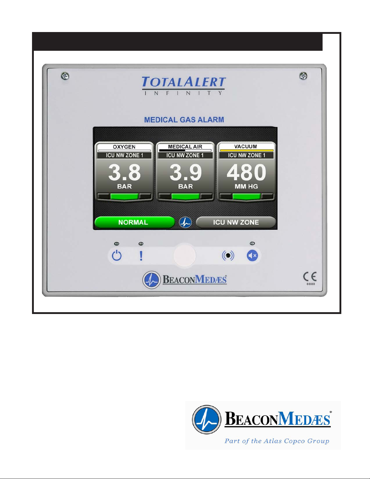
Installation, Operation and Maintenance Instructions
TotalAlert Innity™ HTM Medical Gas Notication System
Part number 4107 9016 60
Revision 01
December 18, 2017
Page 2

Page 3

Page 4

Page 5

Installation, Operation and Maintenance Manual
TotalAlert Innity™ HTM Medical Gas Notication System
This unit is purchased from:
Date purchased:
Model number:
Part number:
Option(s) included:
Any information, service or spare parts requests should be directed to:
BeaconMedæs
Telford Crescent, Staveley,
Derbyshire, S43 3PF, England
Telephone: +44 (0) 1246 474 242
BeaconMedæs reserves the right to make changes and improvements to update products
sold previously without notice or obligation.
Part number 4107 9016 60
Revision 01
December 18, 2017
Page 6

Page 7

TotalAlert Innity™ HTM Medical Gas Notication System
Table of Contents
0.0 Safety Symbols / Environmental Protection
0.1 Safety Symbols
0.2 Environmental Protection
1.0 Introduction
1.1 Product Identication
1.2 User Interface Layout
1.2.1 TotalAlert Innity™ Features
1.2.2 Central Alarm
1.2.3 Zone Alarm
1.2.4 Combination Alarm
1.2.5 Boards
1.3 Denition of Statements
1.4 Denitions
1.5 Alarm Congurations
1.5.1 Central Alarms
1.5.2 Zone Alarms
1.5.3 Gas Combination Alarms
1.6 Electromagnetic Compatibility
1.6.1 EN 60601-1-2
1.7 TotalAlert Innity™ Medical Gas Notication System Parent Model Number Chart
2.0 Installation Procedures
2.1 Surface Mount Box
2.2 Gas Sensor Installation
2.2.1 Remotely Installed Sensors in Pipeline
2.3 Wiring
2.3.1 General Requirements
2.3.2 Wire Type And Size
2.3.3 Determining Number Of Conductors
2.3.4 Power Supply
2.3.5 B60 Gas Input Board
2.3.6 B30 Signal Input Board
2.3.7 B4X Relay Output Board
2.3.8 B50 4-20mA Combination Board
i
4107 9016 60.01
Page 8

TotalAlert Innity™ HTM Medical Gas Notication System
Table of Contents (continued)
2.3.9 Alarm Panel “Mirroring”
2.3.10 General Fault Relay
2.3.11 Ethernet
2.3.12 Field Wiring Cable Shield Grounding
2.3.13 BACnet
2.4 Finish Assembly
2.4.1 Front Panel Mounting
3.0 Wiring Schematics
3.1 HTM Central Wiring Diagram
3.2 HTM Zone Wiring Diagram
3.3 HTM Combination Wiring Diagram
4.0 Operation
4.1 Overview
4.1.1 Main Screen
4.1.2 Gas Badge
4.1.3 Source Signals
4.1.4 Toolbar
4.1.5 Fault Status
4.1.6 Display Screens
4.2 Alarm Conguration
4.3 Setting Up a Zone Alarm
4.3.1 Conguring Gas ID Badges
4.3.2 Initial Setup of an Uncongured Zone Alarm
4.4 Setting Up a Central Alarm
4.4.1 Conguring Source Badges
4.4.2 Initial Setup of an Uncongured Central Alarm
4.4.3 Maintenance Mode Setup
4.5 Setting Up a Combination Alarm
4.5.1 Conguring Source Badges
4.5.2 Conguring Gas ID Badges
4.5.3 Initial Setup of an Uncongured Combination Alarm
4.5.4 Miscellaneous Tab
4.6 Customized Instructions Set Up
4 .7 Additional Components
4.7.1 4-20 mA Devices
4107 9016 60.01
ii
Page 9

TotalAlert Innity™ HTM Medical Gas Notication System
4.7.2 Relay Output Board (B4X Board)
4.7.3 Wired Ethernet Setup
4.7.4 BACnet Set-Up
4.7.5 “Mirroring” Two Alarm Panels
4.8 Medipoint/Shire Network
4.8.1 Medipoint Network
4.8.2 Medipoint Network Setup
4.8.3 Medipoint Network Gas Badge Setup
4.8.4 Shire Network Setup
4.8.5 Shire Network Gas Badge Setup
4.9 Website
4.9.1 Navigating the Website
4.9.2 Website Set-Up
4.10 Wireless Ethernet Set-Up
5.0 Retrot
5.1 Retrot of MP26 or MP125 Concealed Mounted Alarm Panels
5.1.1 Remove Components from Existing Alarm
5.1.2 Install New Components
6.0 Maintenance
7.0 Troubleshooting
8.0 Central Alarm Signal Input Data
9.0 Non-Latin Language Website
9.1 Website Login
9.2 Area Alarm Conguration - Website
9.3 Central Alarm Conguration - Website
9.4 Combination Alarm Conguration - Website
iii
4107 9016 60.01
Page 10
TotalAlert Innity™ HTM Medical Gas Notication System
0.0 Safety Symbols /
Environmental Protection
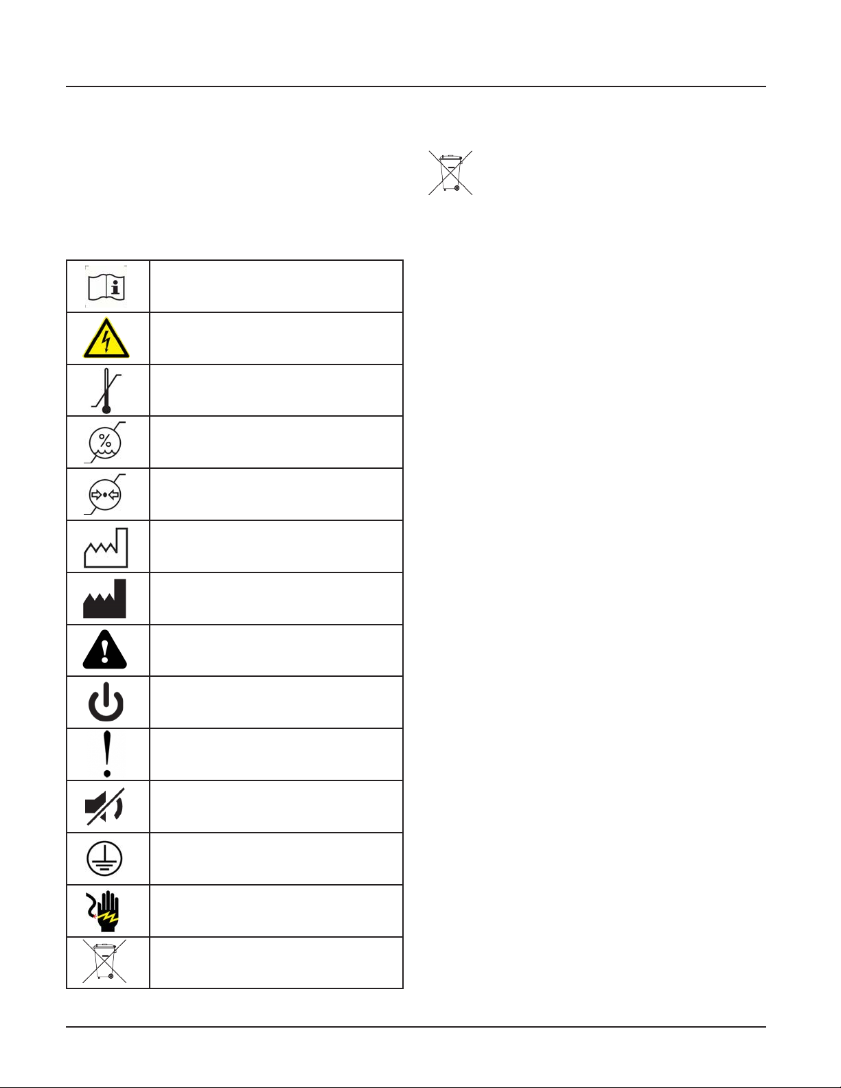
0.1 Important symbols for safety,
storage and handling
Read Instructions
Warning - dangerous voltage
Ambient temperature
Ambient humidity range
Ambient pressure range
0.2 Environmental Protection
Do Not Dispose of in General Waste.
This unit and/or components may be discarded
in any standard refuse facility. The unit does
not contain any hazardous substances.
Date of manufacture
Location of manufacture
Caution - Means there is a possibility
of damage to unit or other property
Power on
Alarm system fault
Mute switch
Protective earth
Shock hazard - Means there is a
possibility of electric shock
Do not dispose of in general waste
4107 9016 60.01
iv
Page 11

Page 12
TotalAlert Innity™ HTM Medical Gas Notication System
1.0 Introduction
1.1 Product Identication
Each alarm is identied by a Reference number, Item
number, and Lot Code.
Installation procedures vary depending on the alarm
conguration.
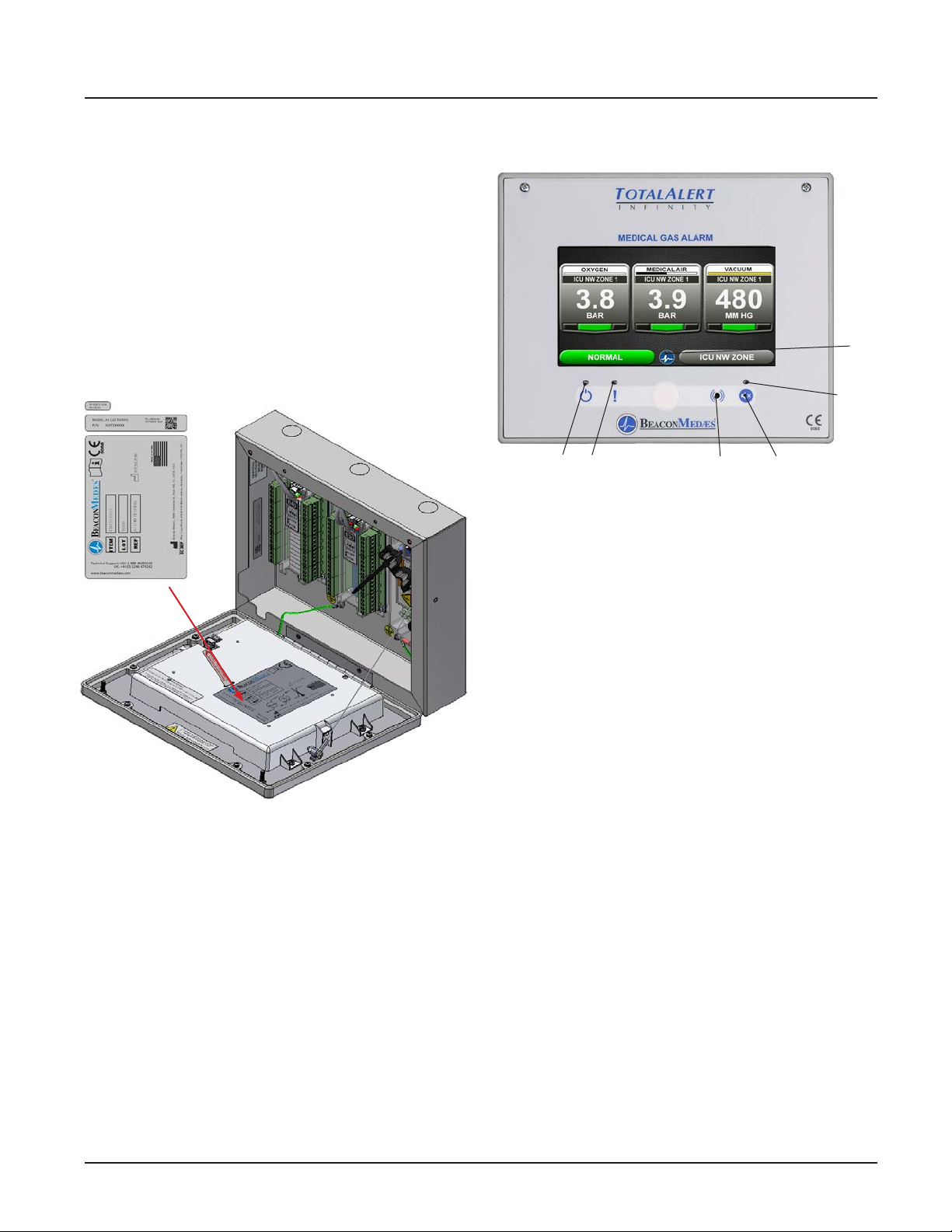
The product ID label is located on the inside of the
alarm back box (Figure 1.1).
1.2 User Interface Layout
Power LED Alarm System
Fault LED
Warning
Figure 1.2: User Interface Layout
Home
Button
Mute
Indicator
LED
Mute ButtonAudible
Figure 1.1: Product Identication Labels
1.2.1 TotalAlert Innity™ Features:
• 8” Touch Screen LCD Display.
• User-dened Instructions for Hospital Response
Plan
• 10/100base-T Wired Ethernet Connection
• WIFI 802.11 b/g/n interface
• Embedded Web server for viewing alarm
information through a computer or tablet
• Electronic Notication of Alarms through e-mail/
text messaging
• History Event Log for Documentation
• Electronic User-dened Gas Labels for any mixes
• Electronic User-dened Location Labels
• Ability to “mirror” alarms from other panels using
the wired Ethernet interface
1-1
4107 9016 60.01
Page 13
TotalAlert Innity™ HTM Medical Gas Notication System
1.2.2 Central Alarm
Features:
Displays a maximum of 24 signals. Combinations can
include:
• Locally wired BeaconMedaes Line Contact
Monitored Signals (Up to 20)
• Medipoint/Shire Network signals
• Ethernet Wired signals (From up to 8 panels)
1.2.3 Area Alarm
Features:
Monitors up to 8 Digital gas sensors.
• Digital pressure/vacuum read out with Low/
Normal/High indicators
• Customizable gas ID labels with user-dened
location labels for each monitored gas
• 1/4” BSPP connection on gas sensors
• Gas Specic Digital ID for each gas sensor
1.2.4 Combination Alarm
1.2.5 Boards
NOTE:
I = 4-20mA Inputs
X = Source Signal Inputs
Y = Dry-Contact Relay Outputs
D = Digital Gas Sensor Inputs
B03 Advance Board
Features:
Contains hardware for advanced features of the
TotalAlert Innity™ Alarm.
Monitors a mix of BeaconMedaes plant signals, digital
gas sensor modules, and 4-20mA transducers.
Features:
• User-dened values for monitoring any two or
three-wire 4-20mA transducer
Figure 1.3: B03 Advanced Board
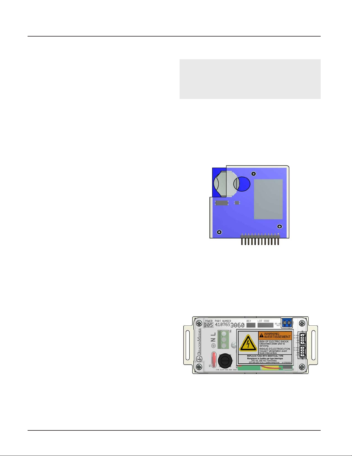
B05 Power Supply Board
Features:
• Supplies 24VDC to all circuit boards in the alarm.
Figure 1.4: B05 Power Board
4107 9016 60.01
1-2
Page 14
TotalAlert Innity™ HTM Medical Gas Notication System
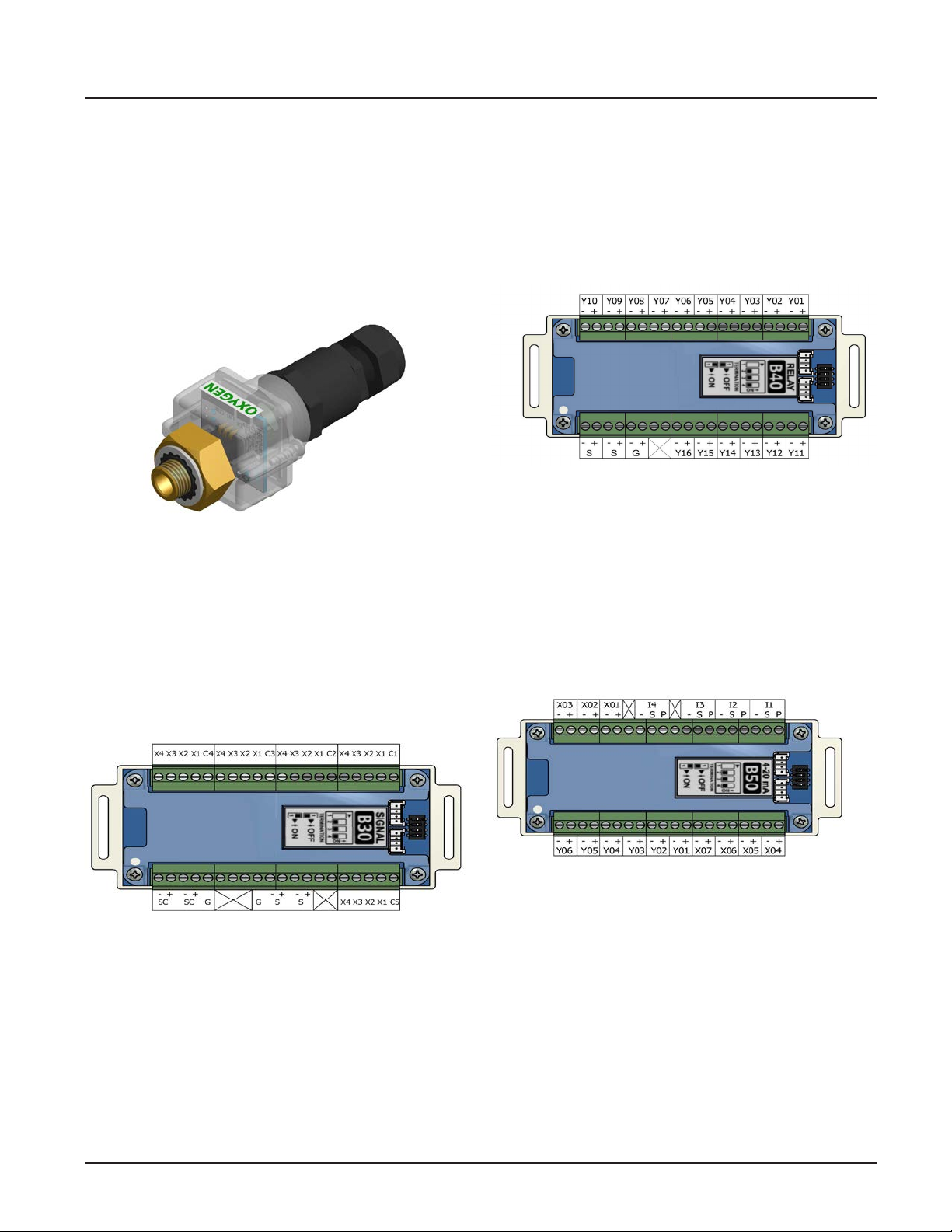
B06 Digital Gas Sensor Board
Features:
• Monitors the Pressure/Vacuum from the pipeline,
and provides a gas-specic digital signal for the
alarm.
• Heartbeat indicator to indicate proper operation.
• Embedded in the gas sensor
Figure 1.5: B06 Digital Gas Sensor Board
B30 Digital Gas Sensor Board
B40, B41 Relay Output Boards
Features:
• Provides 16 normally closed dry-contact relay outputs for external monitoring.
• Heartbeat indicator to signal proper operation.
Figure 1.7: B40, B41 Output Boards
B50 4-20mA Combination Board
Features:
Features:
• Monitors up to 20 BeaconMedaes Line Contact
Monitoring signals on each board from source
equipment.
• Heartbeat indicator to signal proper operation.
Figure 1.6: B30 Digital Gas Sensor Board
• Monitors up to four 4-20mA inputs and provides
6 normally closed dry-contact relay outputs for
external monitoring.
• Heartbeat indicator signals proper operation.
Figure 1.8: B50 4-20 mA Combination Board
1-3
4107 9016 60.01
Page 15
TotalAlert Innity™ HTM Medical Gas Notication System
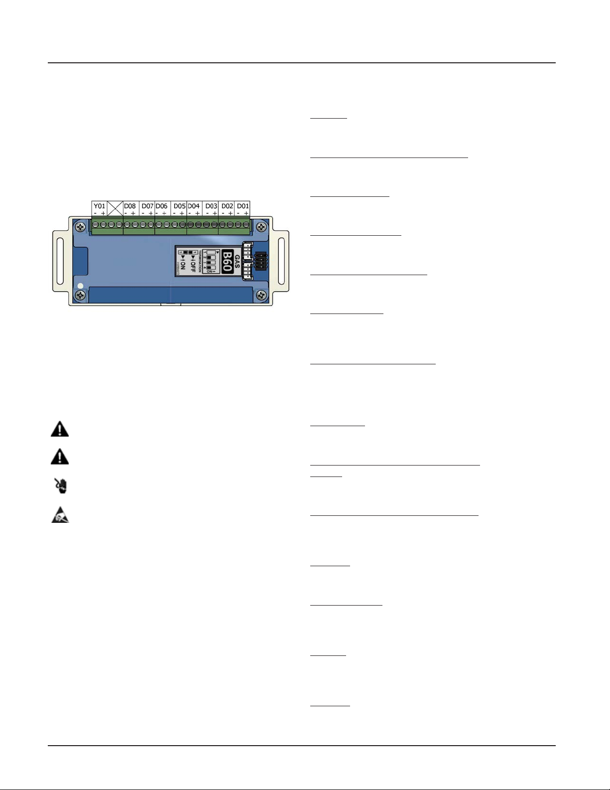
B60 Gas Input Board
Features:
• Monitors up to 8 Digital Gas Sensor Boards. One
normally closed dry-contact relay output is available and opens when any fault occurs.
• Heartbeat indicator signals proper operation.
Figure 1.9: B60 Gas Input Board
1.3 Denition of Statements
Statements in this manual preceded by the following
words are of special signicance.
WARNING: Means there is a possibility of injury
or death to yourself or others.
CAUTION: Means there is a possibility of damage
to unit or other property.
SHOCK HAZARD: Means there is a
possibility of electric shock.
ATTENTION: Means precautions for handling
electrostatic sensitive devices are to be observed.
NOTE: Indicates points of particular interest for more
ecient and convenient operation.
1.4 Denitions
4-20 mA
Input which monitors a two or three-wire 4-20mA
transducer.
Address Resolution Protocol (ARP)
Protocol used by a device to learn the MAC address of
another device so it can send an Ethernet packet.
Area Alarm Panel
Alarm panel that monitors medical gas and vacuum
systems serving a specic Area.
Central Alarm Panel
Alarm panel that monitors medical gas and vacuum
source equipment and main pipelines.
Combination Alarm Panel
Alarm panel that combines features of a Central alarm
panel and an Area alarm panel.
Crossover Cable
Network cable that swaps transmit and receive pairs so
cable can be used to connect two computers or devices
without the use of a hub or switch.
Domain Name Server (DNS)
A device that has a list of device names matched to IP
addresses. Browsers use this resource to locate the
IP address of a named device. NetBIOS name service
provides this function on a local network.
Dry-Contact
Electrical contact isolated or unconnected from any
electrical source.
Dynamic Host Conguration Protocol
(DHCP)
A protocol used by a server to assign IP
addresses to devices and computers.
Electromagnetic Compatibility (EMC)
Verication that a product meets required standards
for emissions of and immunity from electromagnetic
energy in its intended environment.
Ethernet
A standard high-speed network medium specied by
IEEE standard 802.3.
Ethernet Switch
A device that connects many Ethernet devices together
with optimization. Message destinations are examined
and passed only to the correct device.
Firewall
A computer or computer software that prevents unauthorized access to private data from outside computer
users.
Gateway
A computer or device that connects two computer
networks together (such as a private network and the
Internet).
4107 9016 60.01
1-4
Page 16
TotalAlert Innity™ HTM Medical Gas Notication System
General Fault Relay
Single-pole single-throw dry-contact relay output. Used
to activate remote alarm or building management
system. Relay will open whenever ANY audible alarm
on panel is in progress. General Fault Relay will close
only after alarm condition is corrected and alarm panel
resumes normal status.
Hyper Text Transfer Protocol (HTTP)
Protocol used to manage the request and transfer of
web pages to a computer.
Internet Protocol (IP) Address
Unique number that identies a device on a network.
LED
Light Emitting Diode
Media Access Control (MAC) Address
A unique hardware address of a device on an
Ethernet.
NetBIOS Name Service
Local method of addressing a device by name. This
allows a web browser to reference a device by name
instead of an IP address, such as 192.168.2.3.
Remote Sensors
Pressure / vacuum sensors mounted outside of alarm
panel back box. Sensor assemblies may be mounted
separately or ganged together near pressure / vacuum
pipelines. Sensors must then be wired to alarm panel.
Simple Mail Transfer Protocol (SMTP)
Protocol for sending e-mail on a network.
Subnet Mask
A binary number used to separate the network portion
from the host portion of a network address.
SMTP Client
Computer or device that uses SMTP to send e-mail by
communicating with an SMTP server. The TotalAlert
Innity™ Medical Gas Notication System acts as an
SMTP client.
SMTP Server
Computer or device that uses SMTP to receive e-mail
from an SMTP client and then transfer it across the
internet.
Transmission Control Protocol (TCP)
Protocol used to send data streams between two devices. TCP guarantees reliable and in order data from
sender to receiver.
User Datagram Protocol (UDP)
Protocol used to send short messages between computers. UDP does not guarantee reliable transmission
(packets may be lost, duplicated or out of order), but is
faster and more ecient than TCP.
1.5 Alarm Congurations
All TotalAlert Innity™ alarm panels are factory
pre-congured. Conguration of alarm panel varies
dependent upon customer’s requirements.
Three types of alarm panels are available.
• Central alarms
• Area alarms
• Combination alarms
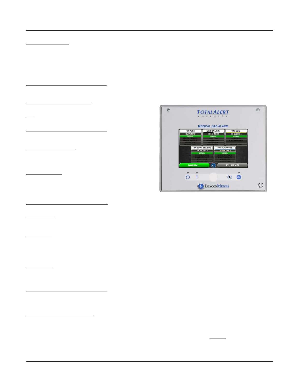
Figure 1.10: Central Alarm Front Panel
1.5.1 Central Alarms
Central alarm panels include the following modular
components:
• Signal input board (B30) that can accept 20 signals
per board; maximum of 1 board.
• Relay boards (B40, B41) that can be used to control
16 dry-contact signals per board; maximum of 2
boards.
Central alarm panels can monitor 20 switched inputs.
Inputs can be assigned to any gas service indicators.
Model Number Scheme:
____ - _______ - ____
Series - Conguration - Retrot
See Model Number Chart in Section 1.7.
Example:
TotalAlert Innity™ Central 20X 16Y
Example Model Number: A3-M11
1-5
4107 9016 60.01
Page 17
TotalAlert Innity™ HTM Medical Gas Notication System
1.5.2 Area Alarms
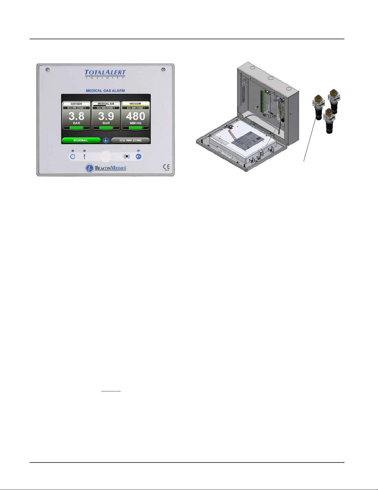
Figure 1.11: Area Alarm Front Panel
Figure 1.12: Remote Sensors
Area alarm panels include the following modular
components:
• Gas Sensor input board (B60) that are used for up
to 8 digital sensors modules
• Digital gas sensor module (B06), can be mounted
remotely on the gas pipeline. A maximum of 8 digital gas sensor modules are allowed per Area alarm
panel.
Area alarm panels may be congured for 1 to 8 gas
inputs. If alarm is congured with gas inputs, the
sensors will be included for connection to pressure/
vacuum pipeline.
Sensors have a 1/4” BSPP male tting for attaching to
the hospital pipeline.
Sensor modules are
mounted outside alarm
backbox
Model Number Scheme:
____ - _______ - ____
Series - Conguration - Retrot
See Model Number Chart in Section 1.6.
Example:
TotalAlert Innity™ Area Alarm
Example Model Number: A3-A10
4107 9016 60.01
1-6
Page 18
TotalAlert Innity™ HTM Medical Gas Notication System
1.5.3 Gas Combination Alarms
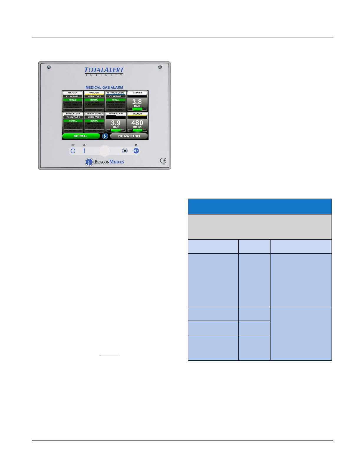
Figure 1.13: Combination Alarm Front Panel
Gas Combination alarms include a mix of the following
modular components:
• B30 board
• B60 board
• B50 board
Combination alarms can monitor up to 20
BeaconMedaes Line Contact Monitoring signal.
Inputs can be assigned to any one of 8 gas service
indicators.
Combination alarms can also monitor up to 6 digital
gas sensors.
Model Number Scheme:
____ - _______ - ____
Series - Conguration - Retrot
See Model Number Chart in Section 1.7.
Example:
TotalAlert Innity™ Combination Alarm
Example Model Number: A3-C10
1.6 Electromagnetic Compatibility
1.6.1 EN 60601-1-2
Medical Electrical Equipment needs special precautions
regarding EMC and needs to be installed and put into
service according to the EMC information provided in
this manual.
Portable and mobile RF communications equipment
can aect Medical Electrical Equipment. The use of
accessories, transducers, and cables other than those
specied by the manufacturer, may result in increased
emissions or decreased immunity of the
TotalAlert Innity.
The TotalAlert Innity should not be used adjacent
to, or stacked with, other equipment. If adjacent or
stacked use is necessary, the TotalAlert Innity should
be observed to verify normal operation in the
conguration in which it will be used.
Guidance and manufacturer’s declaration -
electromagnetic emissions
The TotalAlert Innity is intended for use in the electromagnetic environment specied below. The customer or the user
of the TotalAlert Innity should assure that it is used in such an
environment.
Emissions test Compliance
RF emissions
CISPR 11
RF emissions
CISPR 11
Harmonic emissions
IEC 61000-3-2
Voltage uctuations/
Flicker emissions
IEC 61000-3-3
Group 1
Class A
Class A
Complies
Electromagnetic
environment - guidance
The TotalAlert Innity
uses RF energy only for
its internal function.
Therefore, its RF
emissions are very low
and are not likely to
cause any interference in
nearby electronic
equipment.
The TotalAlert Innity
is suitable for use in all
establishments other
than domestic and those
directly connected to the
public low-voltage power
supply network that supplies buildings used for
domestic purposes.
1-7
4107 9016 60.01
Page 19

TotalAlert Innity™ HTM Medical Gas Notication System
Guidance and manufacturer’s declaration - electromagnetic immunity
The TotalAlert Innity is intended for use in the electromagnetic environment specied below.
The customer or the user of the TotalAlert Innity should assure that it is used in such an environment.
Immunity test
Electrostatic
Discharge (ESD)
IEC 61000-4-2
Electrical fast
transient/burst IEC
61000-4-4
Surge IEC 61000-4-5
Voltage dips, short
Interruptions and
voltage variations
on power supply
input lines IEC
61000-4-11
Power frequency
(50/60 Hz) magnetic
eld IEC 61000-4-8
Note: U
is the a.c. mains voltage prior to application of the test level.
T
IEC 60601
test level
±6 kV contact
±8 kV air
±2 kV for power supply lines
±1 kV for input/output lines
±1 kV dierential mode
±2 kV common mode
<5 % U
T
(>95 % dip in UT)
for 0,5 cycle
<40 % UT
(>60 % dip in UT)
for 5 cycles
<70 % UT
(>30 % dip in UT)
for 25 cycles
<5 % UT
(>95 % dip in UT)
for 5 sec
3 A/m 3 A/m
Compliance level Electromagnetic environment - guidance
±6 kV contact
±8 kV air
±2 kV for power supply lines
±1 kV for input/output lines
±1 kV dierential mode
±2 kV common mode
<5 % UT
(>95 % dip in UT)
for 0,5 cycle
<40 % UT
(>60 % dip in UT)
for 5 cycles
<70 % UT
(>30 % dip in UT)
for 25 cycles
<5 % UT
(>95 % dip in UT)
for 5 sec
Floors should be wood, concrete or ceramic tile.
If oors are covered with synthetic material, the
relative humidity should be at least 30 %.
Mains power quality should be that of a typical
commercial or hospital environment.
Mains power quality should be that of a typical
commercial or hospital environment.
Mains power quality should be that of a typical
commercial or hospital environment. If the user
of the TotalAlert Innity requires continued
operation during power mains interruptions, it
is recommended that the TotalAlert Innity be
powered from an uninterruptible power supply
or battery.
Power frequency magnetic elds should be at
levels characteristic of a typical location in a typical commercial or hospital environment.
Portable and mobile RF communications equipment should be used no closer to any part of
the TotalAlert Innity, including cables, than the
recommended separation distance calculated
from the equation applicable to the frequency of
the transmitter.
Recommended separation distance
d = 1,2√P
Conducted RF
IEC 61000-4-6
Radiated RF
IEC 61000-4-3
Note 1: At 80 MHz and 800 MHz, the higher frequency range applies.
Note 2: These guidelines may not apply in all situations. Electromagnetic propagation is aected by absorption and reection from
structures, objects and people.
a. Field strengths from xed transmitters, such as base stations for radio (cellular/cordless) telephones and land mobile radios,
amateur radio, AM and FM radio broadcast and TV broadcast cannot be predicted theoretically with accuracy. To assess the
electromagnetic environment due to xed RF transmitters, and electromagnetic site survey should be considered. If the
measured eld strength in the location in which the TotalAlert Innity is used exceeds the applicable RF compliance level above, the
TotalAlert Innity should be observed to verify normal operation. If abnormal performance is observed, additional measures may be
necessary, such as reorienting or relocating the TotalAlert Innity.
b. Over the frequency range 150 kHz to 80 MHz, eld strengths should be less than 3 V/m.
3 Vrms
150 kHz to 80 MHz
3 V/m
80 MHz to 2,5 GHz
3 Vrms
3 V/m
d = 1,2√P 80 MHz to 800 MHz
d = 2,3√P 800 MHz to 2,5 GHz
where P is the maximum output power rating
of the transmitter in watts (W) according to the
transmitter manufacturer and d is the recommended separation distance in metres (m).
Field strengths from xed RF transmitters, as
determined by an electromagnetic site survey,
a
should be less than the compliance
level in each frequency range.
b
Interference may occur in the vicinity of equip-
ment marked with the following symbol:
4107 9016 60.01
1-8
Page 20
TotalAlert Innity™ HTM Medical Gas Notication System
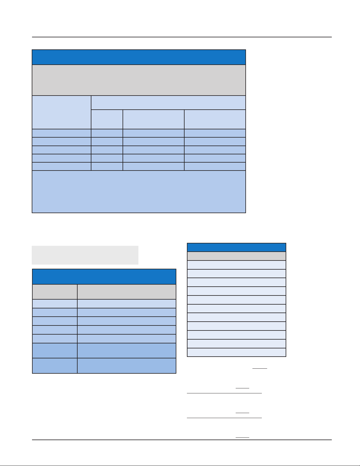
Recommended separation distances between
portable and mobile RF communications equipment and the TotalAlert Innity
The TotalAlert Innity is intended for use in the electromagnetic environment in which radiated
RF disturbances are controlled. The customer or the user of the TotalAlert Innity can help
prevent electromagnetic interference by maintaining a minimum distance between portable
and mobile RF communications equipment (transmitters) and the TotalAlert Innity as recommended below, according to the maximum output power of the communications equipment.
Separation distance according to frequency of transmitter
Rated maximum output
power of transmitter
W
0,01 0,12 0,12 0,23
0,1 0,38 0,38 0,73
1 1,2 1,2 2,3
10 3,8 3,8 7,3
100 12 12 23
For transmitters rated at a maximum output power not listed above, the recommended separation distance d in metres (m) can be estimated using the equation applicable to the frequency
of the transmitter, where P is the maximum output power rating of the transmitter in watts (W)
according to the transmitter manufacturer.
Note 1 At 80 MHz and 800 MHz, the separation distance for the higher frequency range applies.
Note 2 These guidelines may not apply in all situations. Electromagnetic propagation is aected
by absorption and reection from structures, objects and people.
150 kHz to
80 MHz
d = 1,2√P
80 MHz to 800 MHz
d = 1,2√P
m
800 MHz to 2,5 GHz
d = 2,3√P
1.7 TotalAlert Innity™ Medical Gas Notication System Parent Model
Number Chart
Available Gas Sensors
A3 - ___
B
Variable B
Alarm Type and Size
Allowable
Value
A10 Area Alarm, Up to 8 Area Gases
M01 Central, 0 Inputs, 16 Relay Outputs
M02 Central, 0 Inputs, 32 Relay Outputs
M10 Central, 20 Inputs
M11 Central, 20 Inputs, 16 Relay Outputs
C10 Combination, 20 Inputs, Display up to
C40 Combination, 4 Inputs for 4-20 mA
Description
6 Area Gases
devices, 6 Relay Outputs
Description
Oxygen
Nitrous Oxide
Medical Air
Medical Vacuum
Nitrogen
Carbon Dioxide (CO2)
HE-O2 (HE over 80%)
Laboratory Air
Laboratory Vacuum
Surgical Air
O2-N2O
Example: TotalAlert Innity™ Central Alarm with 20 Inputs and 16 Relay
Outputs Example Model Number: A3-M11
Example: TotalAlert Innity™ Area Alarm with 4 gases - Oxygen, Nitrous
Oxide, Medical Air, and Vacuum
Example Model Number: A3-A10
* Gas sensors to be ordered separately
Example: TotalAlert Innity™ Combination Alarm with 20 Inputs, and 3
gases - Oxygen, Medical Air, and Vacuum
Example Model Number: A3-C10
* Gas sensors to be ordered separately
Example: TotalAlert Innity™ Combination Alarm with four 4-420mA
devices and 6 Relay Outputs.
Example Model Number: A3-C40
1-9
4107 9016 60.01
Page 21

Page 22
TotalAlert Innity™ HTM Medical Gas Notication System
2.0 Installation Procedures
2.1 Surface Mount Box
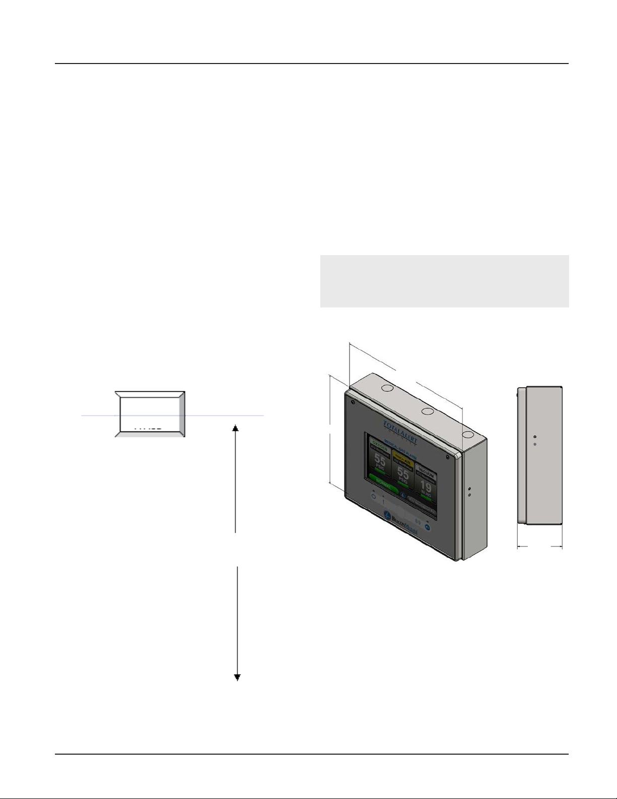
The alarm panel backbox is suitable for both surface
and concealed installation. Installer shall consult with
healthcare facility regarding the location of the alarm
panel. Knock out plugs are provided in the top and
bottom of the box for routing of supply power, Ethernet CAT5 cable, gas sensor wiring. With a concealed
installation a chase depth of 62mm is required and a
bezel is tted to cover the plaster joint. The procedure
to install a rst x alarm panel backbox is as follows.
DO NOT drill the First Fix kit.
1. Remove cardboard dust cover and save for later
use. Installation instructions are provided on the
back for convenience.
2. Ensure the backbox is in the correct orientation.
Locate the backbox at the correct position and
mark out the slots in each corner for the securing
screws. See mounting height requirement (Figure
2.1).
3. Drill wall and t anchors in position.
4. Select cable entry/exit points and remove the
desired knock-out segments from the inside. Fit
suitable grommets/cable glands as required by the
contract specication. Feed cables into the box
leaving 400mm to enable connection to the printed
circuit boards. Secure backbox to the wall with
suitable screws.
5. Reinstall cardboard dust cover to prevent dust and
debris from entering the backbox.
2.2 Gas Sensor Installation
WARNING:
With a concealed installation, the plaster depth
must be ush with the face of the box surface.
282mm
Alarm
Panel
Mounting height range
for local alarm panel
1000-1800 mm
Recommended location -
Nurse base
1800mm
232mm
75.5mm
Figure 2.2: Alarm Panel Backbox Dimensions
Finished Floor Level
Figure 2.1: Local alarm panel mounting height
2-1
4107 9016 60.01
Page 23
TotalAlert Innity™ HTM Medical Gas Notication System
2.2.1 Remotely Installed Sensors in
Pipeline
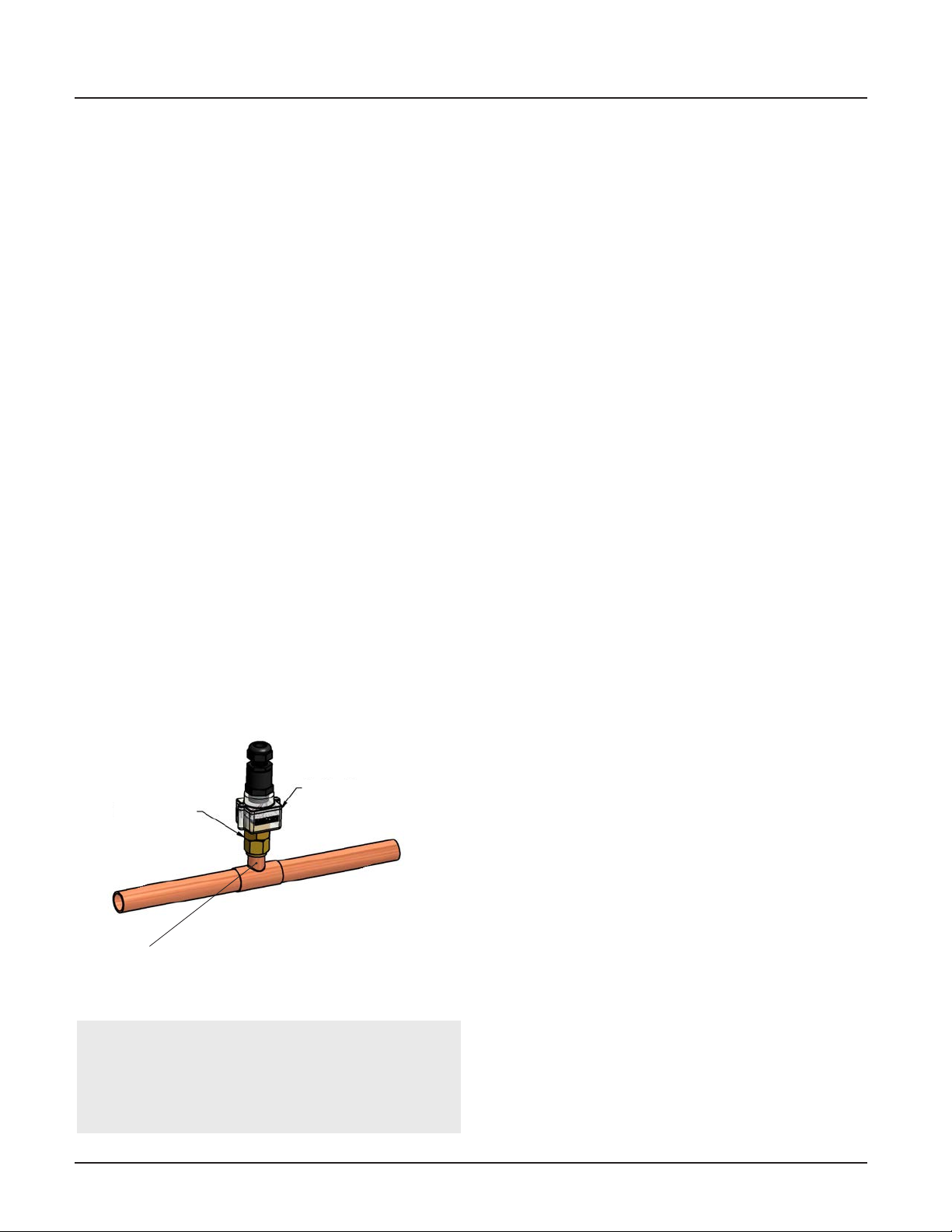
1. Sensors can be installed onto the hospital pipeline
or in a compatible BeaconMedaes Zone Valve
Box. Pressure sensors should be connected to
the pipeline by means of minimum leak devices.
It should not be possible to isolate the sensor
by a manually operated shut-o valve while it is
connected to the pipeline. If a valve is incorporated
for maintenance purposes, it shall be opened by
the insertion of the sensing device.
2. Remove the protective cap and screw sensor into
the ¼” BSPP threaded port in the gas pipeline.
Ensure the Gas ID of the sensor installed matches
with the Gas ID of the pipeline.
3. Remove the black housing from the top of the
sensor to access the wiring terminal block.
4. Route the signal cable through the cord grip and
land the wires to the terminals. Ensure to match
correct polarity of the wires, Red(+), Black(-).
5. Install the black housing to the top of the sensor
and tighten the cord grip onto the cable (see
section 2.3.5).
2.3 Wiring
2.3.1 General Requirements
1. All alarms are to be powered from the Essential
Circuit as required by applicable standards. Mains
operated using 115/230V, 50/60Hz AC.
2. Protect all wiring from physical damage by
raceways or conduit as required by applicable standards. All electrical wiring should be in accordance
with IEE regulations.
3. Wire alarm panels directly to switches or sensors
as required by applicable standards.
4. Wiring runs should be made with color coded wire.
Record color, signal, and source of signal for each
wiring lead to aid in connection of alarm nish
components.
5. Avoid installing alarm panels near radio
transmitters, electrical motors, or switch-gear.
2.3.2 Wire Type and Size
All low voltage wiring must meet the following criteria:
• Copper wire no smaller than 22AWG conductor
insulation at least 0.4mm (0.016in), jacket
insulation at least 0.76mm (0.030in), rated for 300V
and 60°C (140°F) minimum.
• Circuit length not to exceed 100 meters.
• Cable must be twisted-pair shielded type. Multi-pair
cables within one common shield are acceptable.
Gas Specic
1/4" BSPP
Fitting
Connection should be
made on top of pipe
Sensor
NOTE:
If the remote sensor is not installed using a
BeaconMedaes T-Fitting, an orice should be
installed between the pipe and sensor to allow
Figure 2.3: Remote Pipeline Installation
future serviceability.
4107 9016 60.01
All low voltage interconnect wiring between hospital
signaling units must meet the following criteria:
• Copper wire no smaller than 24AWG conductor
insulation at least 0.25mm (0.010in), jacket
insulation at least 0.76mm (0.030in), rated for 300V
and 60°C (140°F) minimum.
• Circuit length not to exceed 1200 meters.
• Cable must be twisted-pair shielded type. Multi-pair
cables within one common shield are acceptable.
2.3.3 Determining Number of Conductors
2-2
Page 24
TotalAlert Innity™ HTM Medical Gas Notication System
The following rules along with references to this
manual’s schematics clarify wiring requirements.
• Digital Gas Sensor Modules
Two conductor cables (must be twisted pair type with
shield) are required for each Gas Sensor module to the
Gas Input board (B60).
Refer to HTM Area Wiring Diagram (Section 3.2).
• BeaconMedaes Line Contact Monitoring
The Total Alert Innity uses BeaconMedaes Line
Contact Monitoring on all input signals. This type of
connection is relatively immune to interference, but
shielded cables are still recommended. Five conductor cables (must be twisted pair) are required for each
channel.
BeaconMedaes recommends the following cable type,
and a maximum length of 100 meters.
Refer to HTM Central / Combination Wiring Diagrams
(Section 3.1 / 3.3) for B30, B50 signal boards.
• Relay outputs
Two conductors are required for each signal between
relay output terminals and remote device (such as
a building automation system). Refer to the wiring
requirements of the connecting device when selecting the appropriate type of conductors to use (i.e. wire
gauge, twisted or not, shielded or not.)
Refer to HTM Central / Combination Wiring Diagrams
(Section 3.1 / 3.3) for B4X signal board.
• Digital display module “mirroring”
Two panels may be connected together so digital
display module pressure reading(s) of rst panel will be
duplicated at second panel.
An eight conductor category 5 CROSS OVER cable is
required for connecting alarm panels directly to each
other. Otherwise, standard cabling can be used with a
facility’s Ethernet hub or switch to set up a connection
between panels.
conductor category 5 network cable is required
between each alarm panel and a facility’s Ethernet hub
or switch.
2.3.4 Power Supply
NOTE:
All wiring shall be protected from physical damage
by raceways or conduit in accordance with local
electrical code.
A power supply assembly is provided with the alarm
panel. The installer must use 18AWG copper supply
wiring minimum with an insulation of not less than
0.8mm (1/32in) thick. Power supply shall be connected
to a building installed circuit breaker. Circuit breaker
shall be a maximum of 15 amps and marked as
disconnecting means for the alarm panel. It is
recommended that the circuit breaker be in close
proximity to the alarm panel and properly selected
according to local regulations.
A knock-out is provided in the lower right hand corner
of the backbox for main power (Figure 2.4). Wiring is to
be installed in accordance with local standards.
No other holes should be punched or used.
Several additional holes or knockouts are provided on
the top panel and bottom for entrance of low voltage
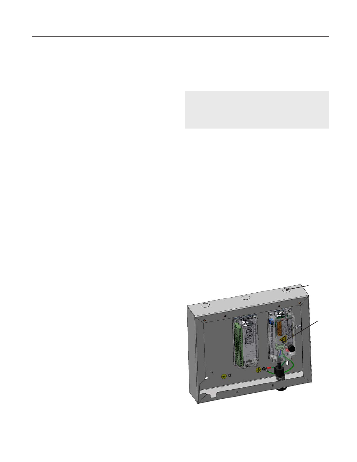
eld wiring (Figure 2.4).
Several additional knock-outs are provided on the top
and bottom of the backbox for entrance of low voltage
Wire Entrance
for power cable
(alternate)
Power Supply
• Source signal “mirroring”
Two panels may be connected together so source
signals of the rst panel will be duplicated at second
panel.
An eight conductor category 5 CROSS OVER cable is
required for connecting alarm panels directly to each
other. Otherwise, standard cabling can be used with a
facility’s Ethernet hub or switch to set up a connection
between panels.
• Ethernet
For each alarm panel to be networked, an eight
2-3
Figure 2.4: Wire Routing
4107 9016 60.01
Page 25
TotalAlert Innity™ HTM Medical Gas Notication System
eld wiring. Alarm panels require 115 to 230VAC
50/60Hz 250mA mains power. Refer to HTM Central,
Area, Combination Wiring Diagrams (Section 3).
For HTM 02-01 compliance, alarm panel must be
connected to the essential power supply of the
electrical system.
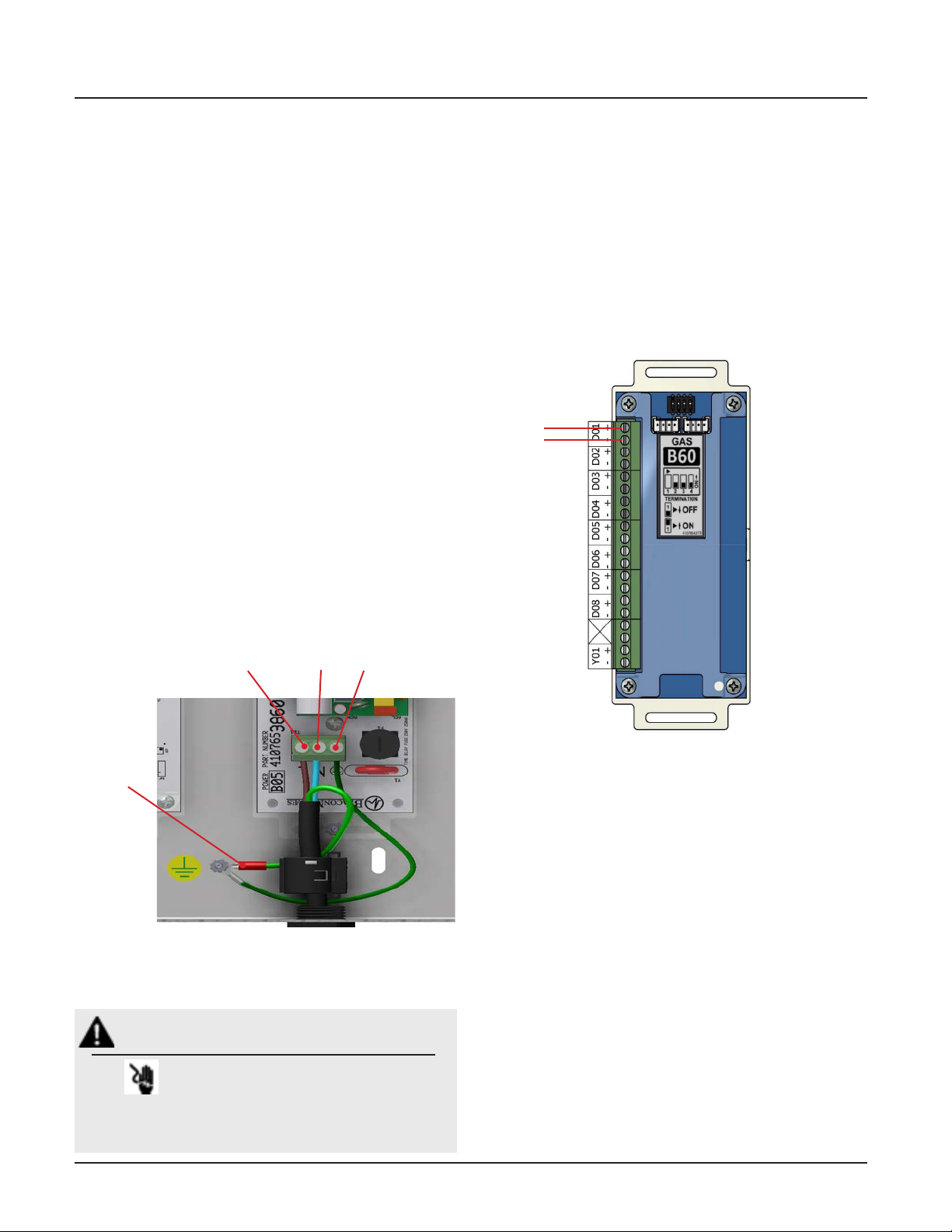
1. Remove the four screws from the plastic power
supply shield
2. Remove the plastic shield from the power supply
3. Connect incoming Live and Neutral wires to the
terminal block. Mains Earth wire connects to the
ring terminal provided on the backbox grounding
stud.
4. DO NOT remove or alter the green factory installed
earth wire from the terminal block to the backbox.
5. Reinstall the plastic power supply shield while
making sure all high voltage wires are contained
within the plastic shield.
6. Secure the plastic shield with four screws.
2.3.5 B60 Gas Input Board
An Area alarm has 8 Gas Inputs. Signals are numbered
D01 thru D08. There is a single relay output for general
gas fault notication.
1. Identify each pair of twisted gas sensor wires inside
the alarm backbox (Figure 2.6).
2. Connect each pair of sensor wires to terminal
blocks noting the correct polarity Red(+), Black (-).
HTM Area Wiring Diagram (Section 3.2).
Mains Earth
WARNING:
Live
Neutral
Chassis Earth
Figure 2.5: Supply Power Wiring
RISK OF ELECTRICK SHOCK
Figure 2.6: B60 Board Wire Routing
Disconnect power at the circuit breaker before
removing power supply shield.
4107 9016 60.01
2-4
Page 26
TotalAlert Innity™ HTM Medical Gas Notication System
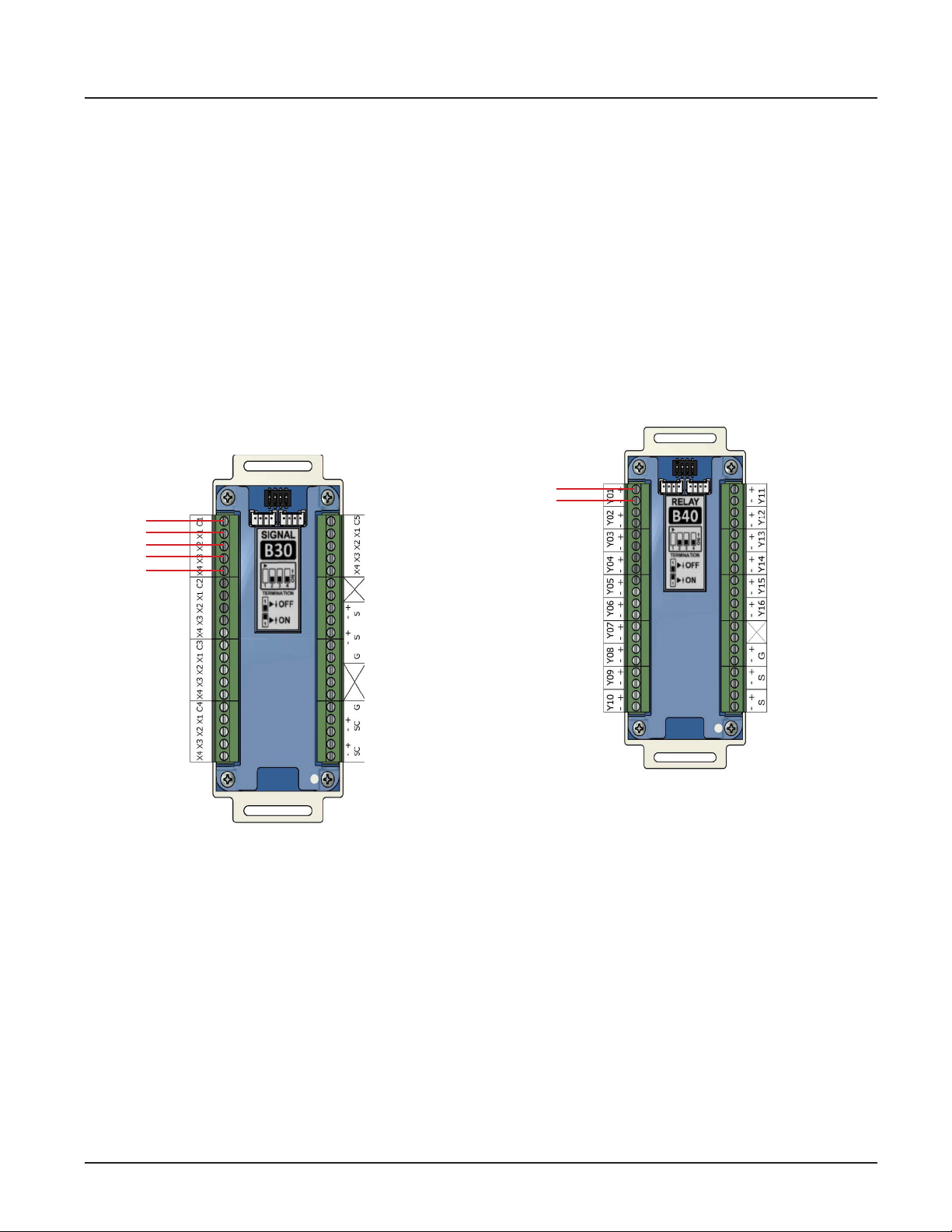
2.3.6 B30 Gas Input Board
A Central or Combination alarm panel can contain a
signal input board, maximum of 1 board or 20
BeaconMeades Line Contact Monitoring signals.
1. Input signals on the B30 board are grouped as
Channels 1-5 with each containing a COM and X1X4.
2. Identify each group of twisted wires that are eld
installed inside the alarm backbox.
3. Route each group of wires as shown in Figure 2.6
to the appropriate terminals on input board. Refer
to HTM Central / Combination Wiring Diagrams
(Section 3.1 / 3.3)
2.3.7 B4X Relay Output Board
A Central or Combination alarm can contain multiple
relay output boards; up to a maximum of 4 boards with
16 relay outputs each. The B4X boards (B40, B41) utilize
normally closed dry contact relay outputs. The outputs
on the B4X boards are labeled Y01 through Y16.
Identify each pair of eld installed relay output signal
wires inside the alarm backbox. Route each pair of
relay output wires as shown in Figure 2.8 to the
appropriate terminals on the relay board. Connect
each pair of signal wires to the terminal blocks, noting
the correct polarity (+,-). Refer to HTM Central/
Combination Wiring Diagram (Section 3.1/3.3).
Figure 2.7: B30 Board Wire Routing
2-5
Figure 2.8: B4X Board Wire Routing
4107 9016 60.01
Page 27
TotalAlert Innity™ HTM Medical Gas Notication System
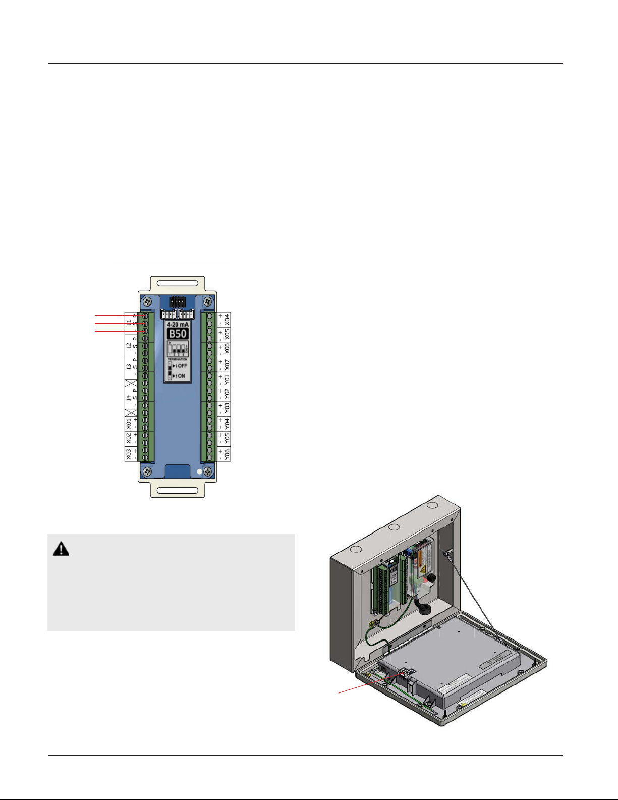
2.3.8 B50 4-20mA Combination Board
A Combination alarm can contain a B50 board that
contains four 4-20mA inputs that can be used with
a two or three-wire transmitter. The board also six
normally closed dry contact relay outputs. Each alarm
panel can have a maximum of one B50 board.
Identify each set of eld installed 4-20mA input signal
wires (2 or 3 wires per set) inside the alarm backbox.
Route each set of input wires to the appropriate terminals on the B50 board. Connect each set of signal
wires to the terminal blocks, noting the correct polarity
(Figure 2.9).
2.3.9 Alarm Panel “Mirroring”
Each alarm panel has an Ethernet port on the back of
the front panel assembly. By connecting the alarm to
the hospital network, via Ethernet, or directly cabling it
to another alarm panel, signals and gas pressures can
be pulled from one panel and displayed on another
panel.
A category 5 CROSS OVER cable is required for connecting alarm panels directly to each other. Otherwise,
standard cabling can be used with a facility’s Ethernet
hub or switch to connect panels.
2.3.10 General Fault Relay
The B60 Gas Input board is supplied with an alarm
panel general fault output relay.
This relay has a set of dry contacts that is wired
normally closed.
The relay will activate when ANY alarm on the ENTIRE
alarm panel is activated. Relay will remain activated as
long as alarm condition is active, even if audible alarm
is silenced by MUTE button.
When alarm condition is corrected, relay will
deactivate. Relay contact ratings are 5A @ 30VDC / 3A
@ 250VAC. Refer to HTM Area Wiring Diagram (Section
3.2).
Figure 2.9: B50 Board Wire Routing
CAUTION:
Source equipment signal wires must be connected
to normally-closed, dry contacts. No electrical voltage can be present and contacts must be closed
during normal equipment operation. When contacts open, an alarm condition will be activated.
2.3.11 Ethernet
Alarms can be connected to a facility’s network via
Ethernet by plugging the network cable to the port
provided on the back of the alarm front panel.
Ethernet
Connection
4107 9016 60.01
Figure 2.10: Ehernet Connection
2-6
Page 28
TotalAlert Innity™ HTM Medical Gas Notication System
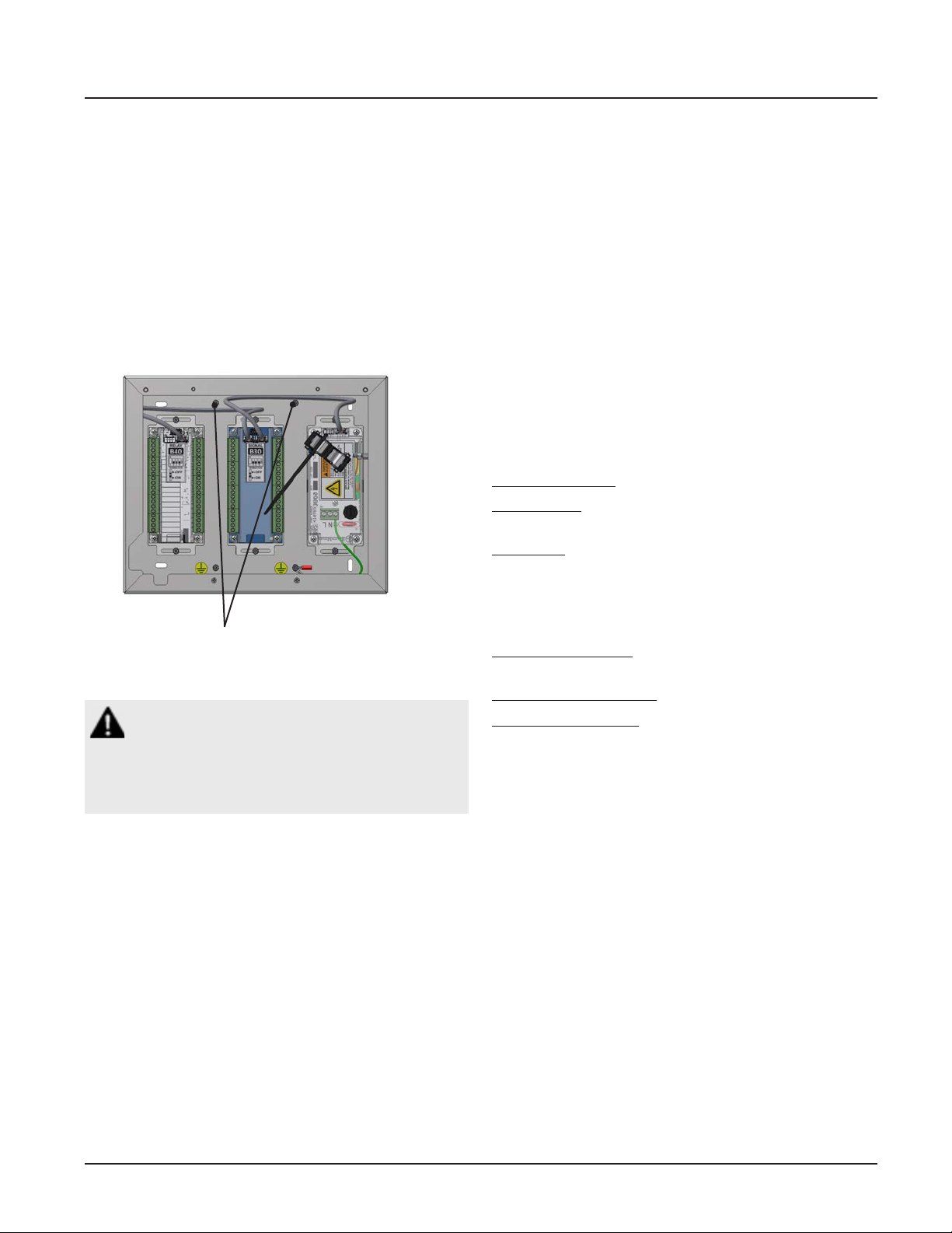
2.3.12 Field Wiring Cable Shield
Grounding
All eld wiring cable shields must be grounded inside
alarm panel back box.
Studs are provided in the top and bottom of the alarm
back box for ring terminals (Figure 2.11).
Shields from several cables may be wrapped together
and crimped into one ring terminal (by others).
Grounding Studs
Figure 2.11: Cable Shield Grounding-Zone
CAUTION:
Keep shield wires to ground screw as short as
possible so they can not touch front panel circuit
boards when front panel is closed.
2.3.13 BACnet
The BeaconMedæs TotalAlert Innity™ HTM control
systems utilize the TCP/ IP family of protocols for
communication and each alarm has a unique IP
address.
Each BACnet enabled TotalAlert Innity™ alarm
conforms to the BACnet protocol.
• Protocol Implementation Conformance
Statement
Each BACnet enabled TotalAlert Innity™ alarm has
available a Protocol Implementation Conformance
Statement (PICS). The PICS is a written document
created by BeaconMedæs that identies the particular
options specied by BACnet that are implemented in
the TotalAlert Innity™ alarm.
• BACnet Conformance
BACnet Vendor ID: 543
Alarm Prole: BACnet Smart Sensor (B-SS)
BIBB (BACnet Interoperability Building Blocks)
Supported:
• Read Property - B (DS-RP-B)
• Dynamic Device Binding - B (DM-DDB-B)
• Dynamic Object Binding - B (DM-DOB-B)
Object Type Support: Analog value, Binary value,
Device.
Data Line Layer Options: ISO 8802-3 (“Ethernet”) LAN
Character Set Support: ISO 10646 (UTF-8)
Encoding
2-7
4107 9016 60.01
Page 29
TotalAlert Innity™ HTM Medical Gas Notication System
2.4 Finish Assembly
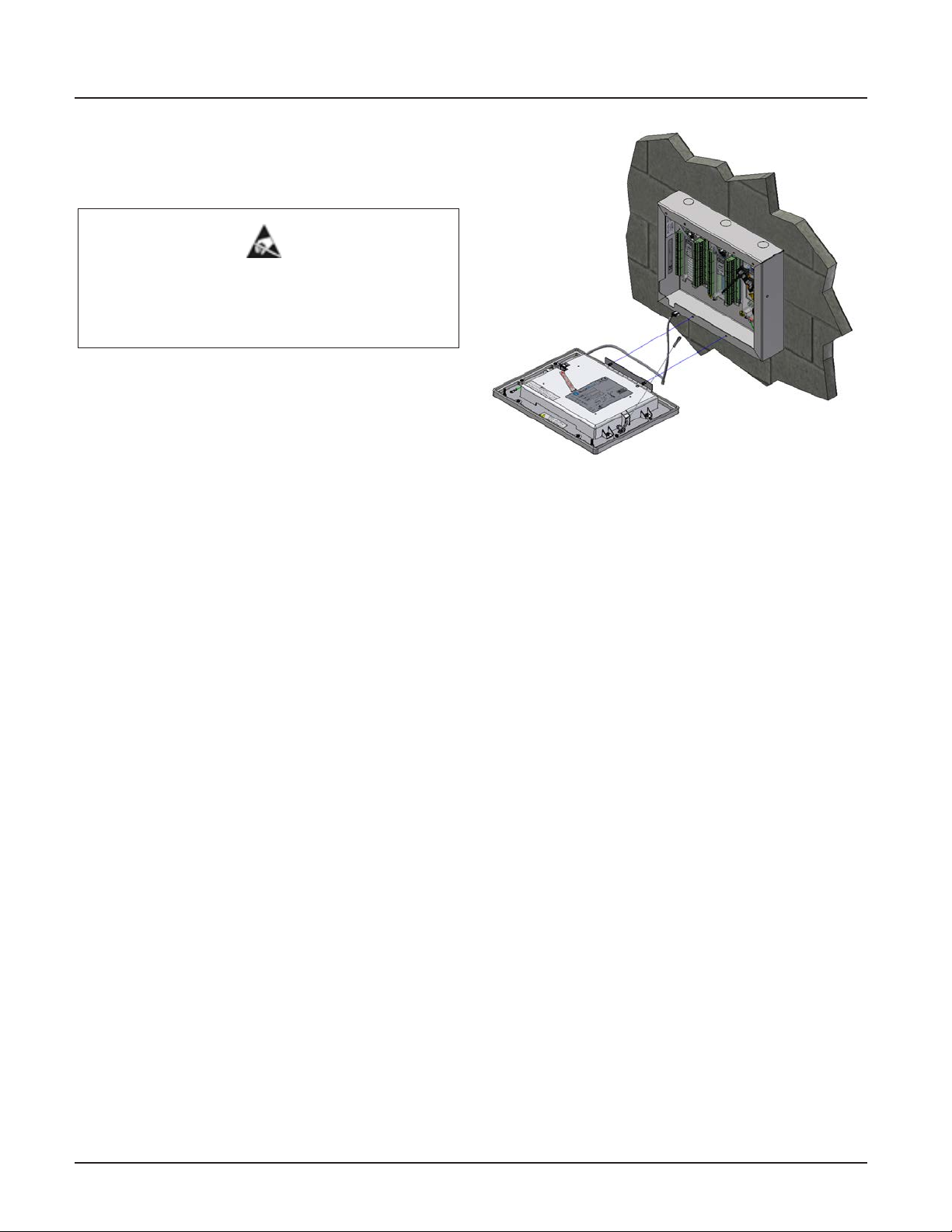
2.4.1 Front Panel Mounting
ATTENTION:
Observe Precautions for Handling
ELECTROSTATIC SENSITIVE DEVICES
1. Remove front panel assembly from packaging.
2. Remove front panel mounting screws from alarm
panel backbox assembly.
3. Remove lanyard mounting nut from alarm panel
back box assembly.
4. Attach front panel to alarm panel backbox using
screws removed in step 2 (Figure 2.12).
5. Attach lanyard to alarm panel backbox using
screws removed in step 3 (Figure 2.12).
6. Remove nut from front panel grounding lug.
7. Install front panel grounding wire using nut
removed in step 6.
8. Connect the grey cable on the front panel to the
open power/communication port on the power
supply.
Figure 2.12: Attach Front Panel and Lanyard
4107 9016 60.01
2-8
Page 30

Page 31
TotalAlert Innity™ HTM Medical Gas Notication System
3.0 Wiring Schematics
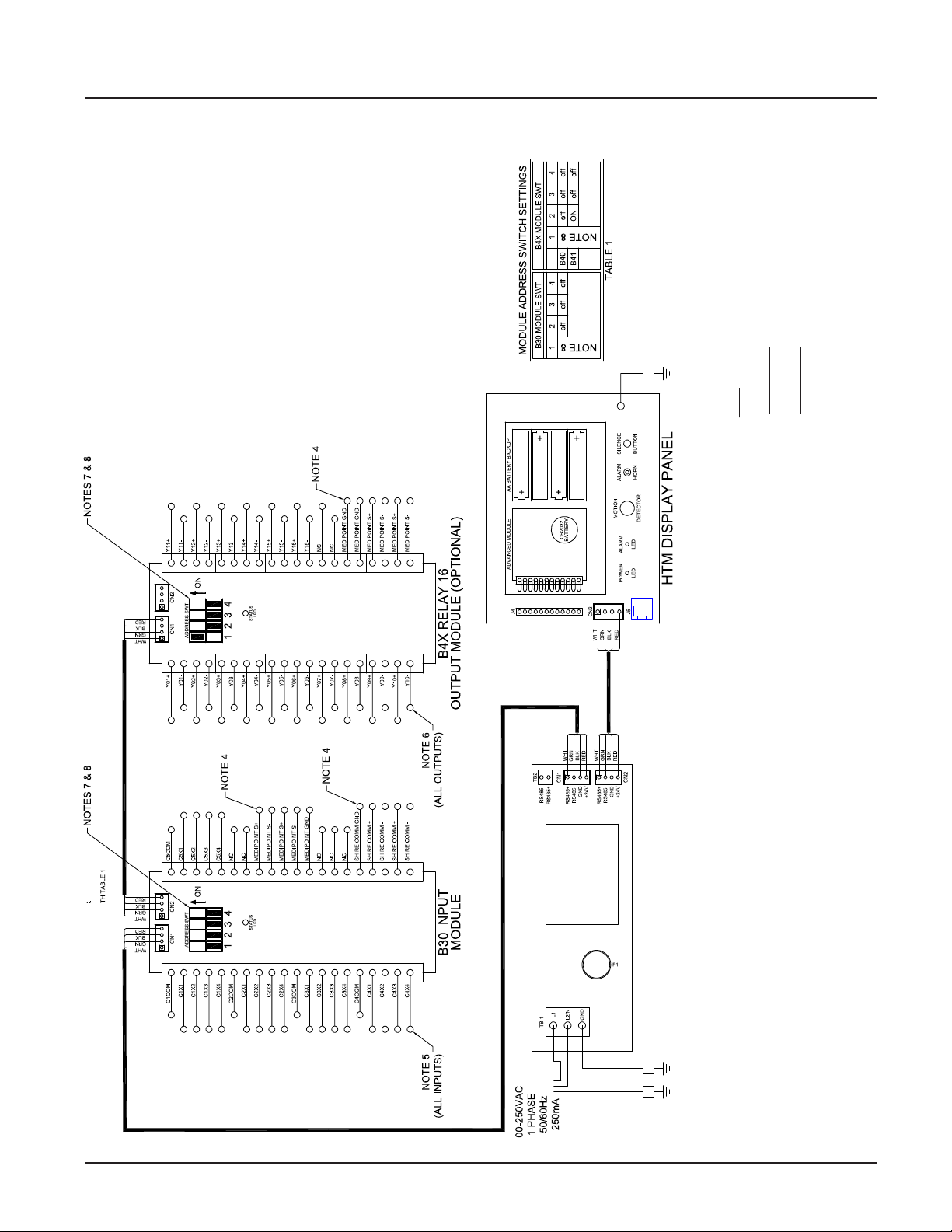
3.1 HTM Central Wiring Diagram
MULTI-CONDUCTOR CABLE MUST BE TWISTED PAIR TYPE WITH SHIELD
TOTAL CIRCUIT LENGTH NOT TO EXCEED 100 METERS
MULTI-CONDUCTOR CABLE MUST BE TWISTED PAIR TYPE WITH SHIELD.
TOTAL CIRCUIT LENGTH NOT TO EXCEED 1200 METERS.
CONTACTS.
NOTES:
1. MAIN DISCONNECT PROVIDED BY OTHERS
2. FIELD POWER WIRING TO BE COPPER RATED FOR 75°C MINIMUM
3. FIELD SIGNAL WIRING TO BE MINIMUM 22AWG
4. MEDIPOINT & SHIRE WIRING TO BE MINIMUM 24 AWG.
5. SIGNAL INPUTS FROM BEACONMEDAES LINE CONTACT MONITORING
6. RELAY OUTPUT CONTACT RATED 3A / 30VDC MAX.
7. SEE MODULE LABEL TO SET MODULE ADDRESS (POSITIONS 2, 3 & 4)
8. SET ADDRESS SWT POSITION 1 TO “ON” FOR LAST MODULE IN CHAIN ONLY.
3-1
FACTORY WIRED
CHASSIS GROUND
ENCLOSURE
GROUND
Figure 3.1: Wiring Diagram for TotalAlert Innity™ Central Alarm
SCREW
4107 9016 60.01
Page 32
TotalAlert Innity™ HTM Medical Gas Notication System
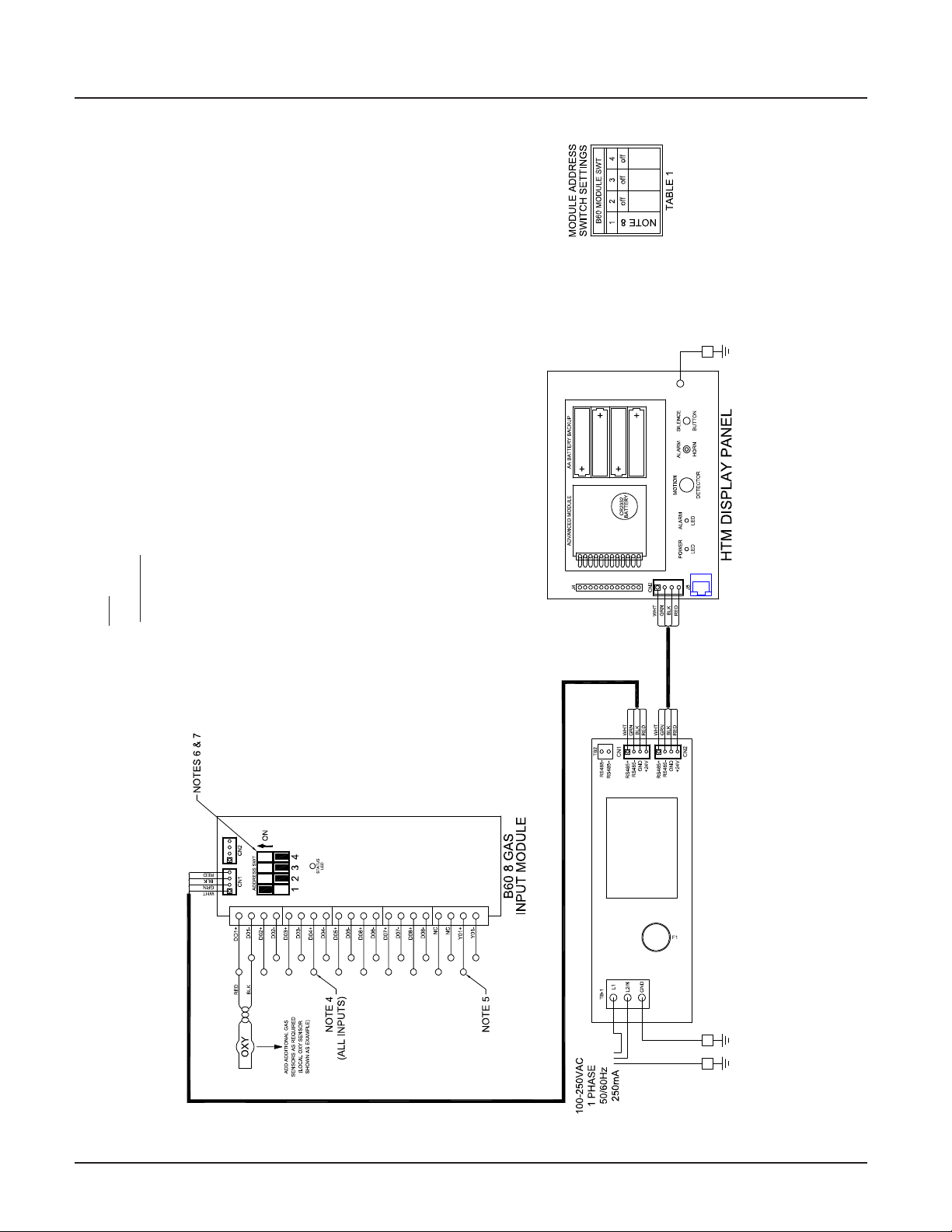
3.2 HTM Area Wiring Diagram
MULTI-CONDUCTOR CABLE MUST BE TWISTED PAIR TYPE WITH SHIELD.
TOTAL CIRCUIT LENGTH NOT TO EXCEED 100 METERS.
NOTES:
1. MAIN DISCONNECT PROVIDED BY OTHERS
2. FIELD POWER WIRING TO BE COPPER RATED FOR 75°C MINIMUM
3. FIELD SIGNAL WIRING TO BE MINIMUM 22AWG
4. SIGNAL INPUTS (UP TO 8) FROM GAS SENSOR MODULES.
5. RELAY OUTPUT CONTACT RATED 3A / 30VDC MAX.
6. SEE MODULE LABEL TO SET MODULE ADDRESS (POSITIONS 2, 3 & 4)
7. SET ADDRESS SWT POSITION 1 TO “ON” FOR LAST MODULE IN CHAIN ONLY.
FACTORY WIRED
CHASSIS GROUND
Figure 3.2: Wiring Diagram for TotalAlert Innity™ Area Alarm
4107 9016 60.01
3-2
ENCLOSURE
GROUND SCREW
Page 33
TotalAlert Innity™ HTM Medical Gas Notication System
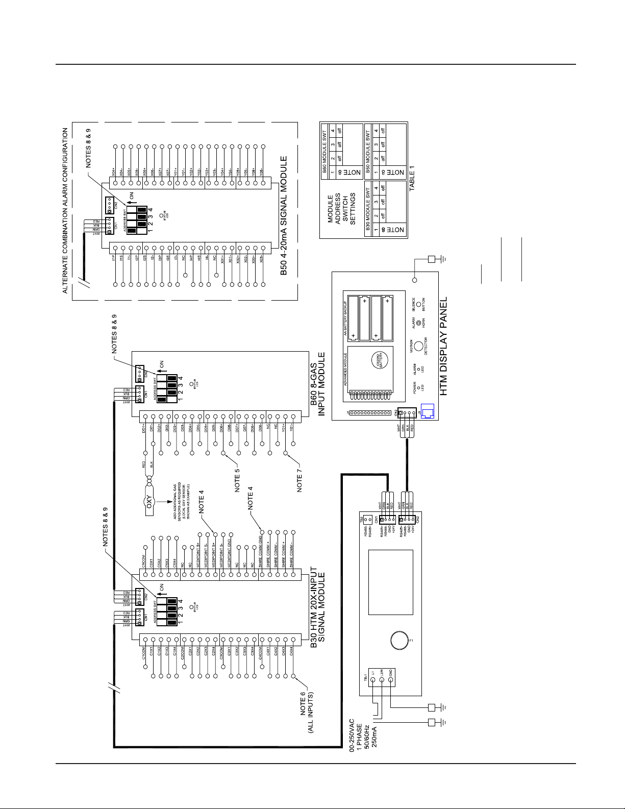
3.3 HTM Combination Wiring Diagram
MULTI-CONDUCTOR CABLE MUST BE TWISTED PAIR TYPE WITH SHIELD
TOTAL CIRCUIT LENGTH NOT TO EXCEED 100 METERS
MULTI-CONDUCTOR CABLE MUST BE TWISTED PAIR TYPE WITH SHIELD.
TOTAL CIRCUIT LENGTH NOT TO EXCEED 1200 METERS.
TABLE 1.
NOTES:
1. MAIN DISCONNECT PROVIDED BY OTHERS
2. FIELD POWER WIRING TO BE COPPER RATED FOR 75°C MINIMUM
3. FIELD SIGNAL WIRING TO BE MINIMUM 22AWG
4. MEDIPOINT & SHIRE WIRING TO BE MINIMUM 24 AWG.
5. SIGNAL INPUTS FROM BEACONMEDAES LINE CONTACT MONITORING CONTACTS.
6. RELAY OUTPUT CONTACT RATED 3A / 30VDC MAX.
7. SEE MODULE LABEL TO SET MODULE ADDRESS (POSITIONS 2, 3 & 4). VERIFY WITH
8. SET ADDRESS SWT POSITION 1 TO “ON” FOR LAST MODULE IN CHAIN ONLY.
3-3
FACTORY WIRED
CHASSIS GROUND
ENCLOSURE
GROUND
Figure 3.3: Wiring Diagram for TotalAlert Innity™ Combination Alarm
SCREW
4107 9016 60.01
Page 34

Page 35
TotalAlert Innity™ HTM Medical Gas Notication System
4.0 Operation
4.1 Overview
The TotalAlert Innity™ Medical Gas Notication
System is a touchscreen gas pressure and system
monitoring alarm created for ease of use.
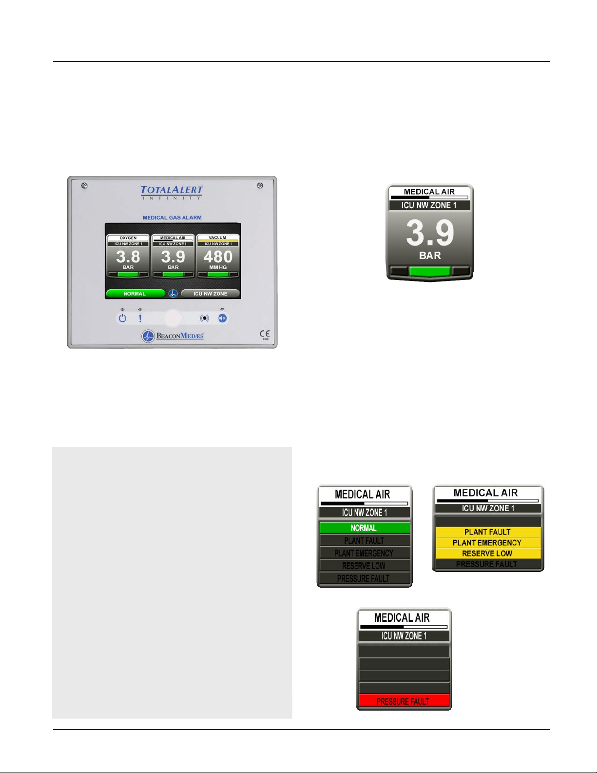
Figure 1: Area Alarm Main Screen
4.1.1 Main Screen
The rst screen that users see on a congured unit is
the MAIN screen. The MAIN screen is the main view for
the alarm and shows the pressure status of all of the
gases or source signals the alarm is monitoring.
NOTES:
The main screen will appear dierent depending
on whether the alarm panel is congured as an
Area, Central or Combination.
An Area alarm main screen will show gas
pressure badges, a central alarm main screen will
show source badges, and a combiantion alarm
main screen will show both gas badges and source
badges.
4.1.2 Gas Badge
Every gas monitored by the alarm will have a gas badge
which will show the following information:
• Gas being monitored
• Location where gas is being used
• Gas pressure value
• Gas pressure status (Low, Normal, or High)
Figure 2: Gas Badge
4.1.3 Source Signals
Every source signal monitored by the alarm will display
the following information once congured:
• Equipment being monitored
• Location of the source equipment
• Signal being monitored
• When all conditions are normal it will show
“NORMAL” in green (Figure 4.3). If the conditions are
out of normal range, it will show yellow (warning).
During a pressure fault condition it will show
“PRESSURE FAULT” in red and the normal message
will disappear (Figure 4.4).
Each source badge can show the status of up to 4
signals.
To provide an aesthetic display and maintain
consistency in accordance with recognized and
established medical gas service sequencing, it is
recommended that displays are positioned in the
following order on each alarm panel starting with
the left hand column:
- Medical Oxygen
- Nitrous Oxide
- Oxygen/Nitrous Oxide Mix (50/50)
- Medical Air 400 kPa
- Medical Air 700 kPa
- Medical Vacuum
4-1
Warning
Normal
Pressure Fault
Figure 3: Source signal status
4107 9016 60.01
Page 36
TotalAlert Innity™ HTM Medical Gas Notication System
NOTES:
To provide an aesthetic display and maintain
consistency in accordance with recognized and
established medical gas service sequencing, it is
recommended that displays are positioned in the
following order on each alarm panel starting with
the left hand column:
- Medical Oxygen (cryogenic and manifolds)
- Nitrous Oxide (manifolds)
- Oxygen/Nitrous Oxide mix 50/50 (manifolds)
- Medical Air 400kPa (plant and manifolds)
- Medical Air/Surgical Air 700kPa (plant and manifolds)
- Medical Vacuum (plant)
- AGS (simplex or duplex)
- Helium/Oxygen mixture
- Point alarms (as required)
Home Button Information Button
Alarm
Button
Conguration
Button
History Button
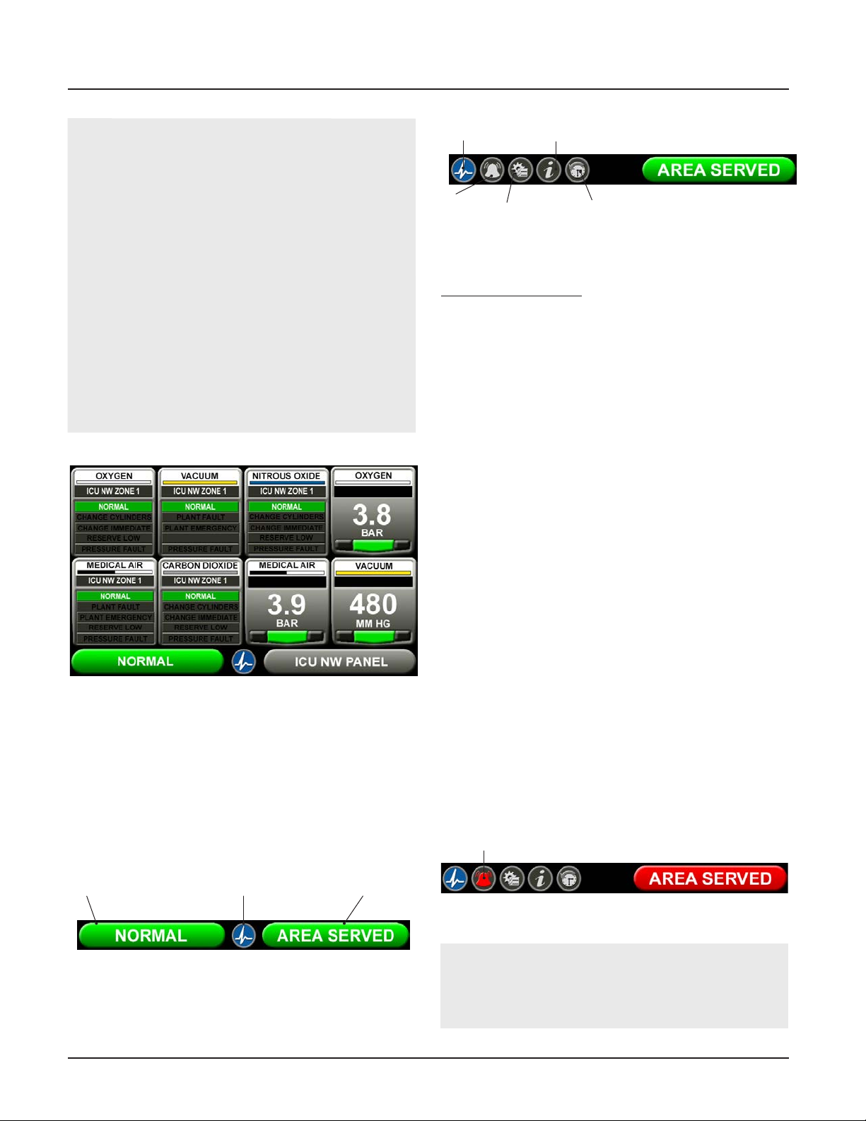
Figure 6: Icon Toolbar
Icons on the toolbar:
1. Home button. This icon button toggles to the MAIN
screen.
2. Alarm button. This icon button toggles to the
ACTIVE ALARM screen.
3. Conguration button. This icon button toggles to
the CONFIGURATION screen.
4. Information button. This icon button toggles to the
INFORMATION screen.
5. History button. This icon button toggles to the
HISTORY screen.
The button that corresponds to the screen currently in
use will be blue.
Figure 4: Combination Alarm Screen
4.1.4 Toolbar
Running from left to right across the bottom of the
MAIN screen is the toolbar. The Normal toolbar is
available when the alarm is operating in normal status
and shows:
Home
Alarm Status (normal)
Figure 5: Normal Toolbar
To switch to the Icon toolbar, touch the HOME button.
Button
Location of Panel
4.1.5 Fault Status
If a gas sensor is measuring above or below the alarm
level, the high or low pressure indicator on the gas
badge will ash for the gas pressure out of range.
If a gas sensor becomes disconnected or shorted, both
high and low indicators for that gas will ash and an
error code and message will be displayed.
If a congured source signal becomes an open circuit,
the source badge and the signal status will change
from green to blinking red.
The Icon toolbar will appear, and the Alarm button will
be ashing red. By default the screen will change to the
Active Alarm Screen.
Users can touch any ashing red light to go to the
ACTIVE ALARM screen.
Alarm Button (Red)
Figure 7: Fault Status
NOTE:
The Normal toolbar will automatically reappear
when all faults are resolved.
4107 9016 60.01
4-2
Page 37
TotalAlert Innity™ HTM Medical Gas Notication System
4.1.6 Display Screens
Active Alarm Screen
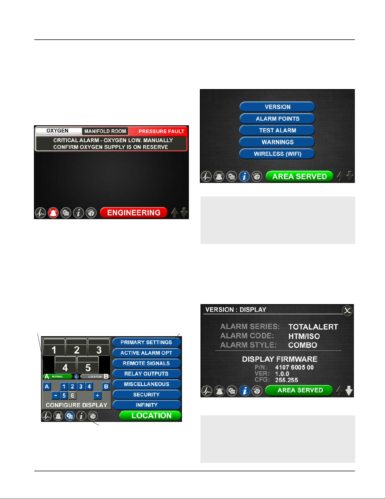
The ACTIVE ALARM screen provides detailed information about pressures or signals that are in alarm
condition. If an active alarm instruction has been set
up, users will also see an instruction on how to respond
to the alarm (see section 4.5 - Customized Instructions
Set Up).
Figure 8: Active Alarm Screen
Conguration Screen
The CONFIGURATION screen is used to congure the
alarm. The conguration screen is only accessible with
a password. It is divided into three parts.
The top left section is the Display section. It contains a
small representative view of the MAIN screen and buttons for conguring the MAIN screen.
The top right section is the Settings section.Tabs not
accessible are grayed out.
The bottom section is the Icon toolbar.
Information Screen
The INFORMATION screen provides pertinent information about the alarm—including high and low alarm
values and rmware details—in one central place.
Figure 10: Information Screen
NOTE:
The Wireless (WIFI) tab is only present on the
information screen if the default setting has been
changed on the WIFI setting screen to allow WIFI
control (See Section 4.9).
Version Tab
Touch the VERSION tab to view details about the:
• Series, code, and style of the alarm
• Firmware version for the main display board and
additional boards
Display
Icon Toolbar
Figure 9: Conguration Screen
Settings
Figure 11: Version Tab
NOTE:
The version screens automatically scroll. Touch
the blinking up or down arrow in the lower right
to stop the automatic scroll and start the manual
scroll.
4-3
4107 9016 60.01
Page 38
TotalAlert Innity™ HTM Medical Gas Notication System
Touch the X button in the upper right to close and
return to the INFORMATION screen.
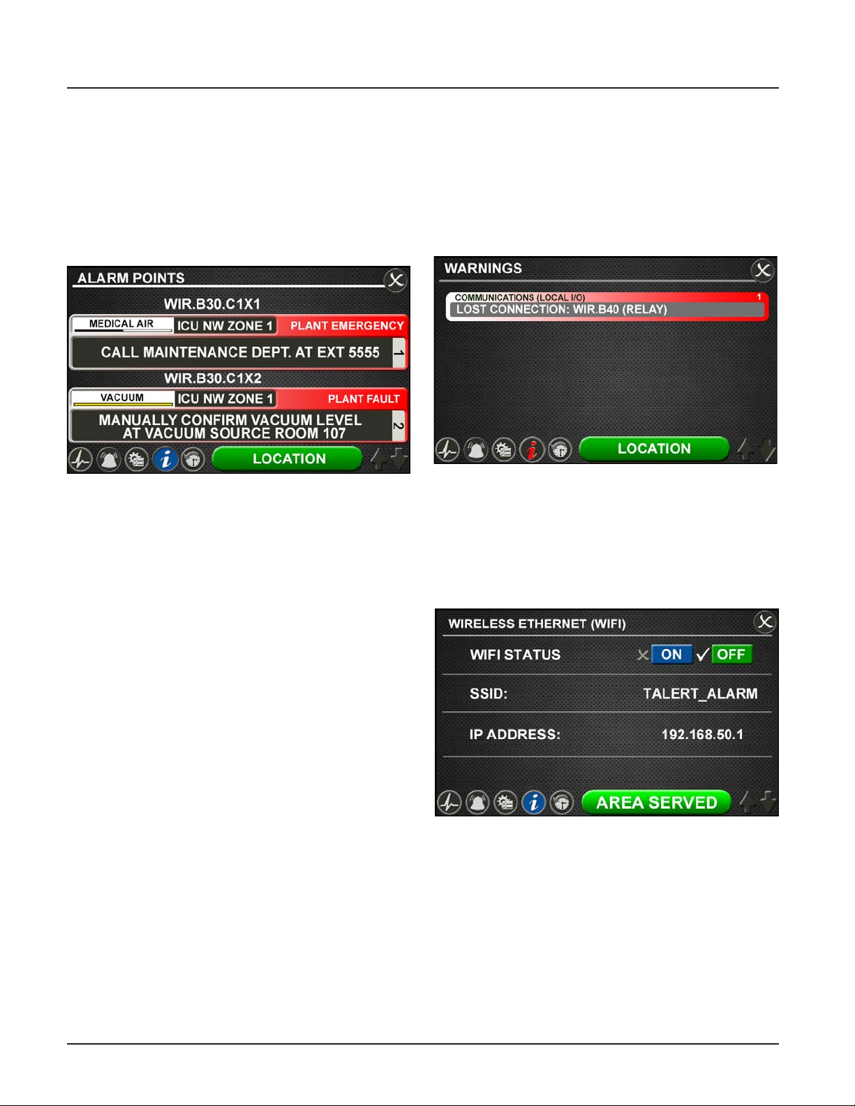
Alarm Points Tab
Touch the ALARM POINTS tab for a quick view of the
alarm points—the low and high set points—for each
gas badge (Area alarm) or source signal conguration
(central alarm).
Figure 12: Alarm Points Tab
This screen provides a complete view of the
conguration and is a fast way to check items such as:
• Location where the pressure sensors and source
signals are physically wired.
• Gases Monitored
• Areas Monitored
• Low and high pressure set points for area signals
• Source Signals Monitored
Touch the X button in the upper right to close and
return to the INFORMATION screen.
Warnings Tab
Touch the WARNINGS tab to view any possible active
warnings that would include lost network communication with manually enrolled devices, lost connection to
a connected/initialized board, or when a central signal
input is wired, but not assigned/programmed to an
alarm signal.
Figure 13: Warnings Tab
WIFI Tab
Touch the Wireless Ethernet (WIFI) tab to view WIFI
Status (On or O), SSID identication, and IP Address.
WIFI Status can be turned On or O by touching the
designated tabs.
Test Alarm Tab
Touch the TEST ALARM tab to run a quick test of the
hardware.
The audible alarm will sound for one-to-two seconds to
test that the horn is working properly.
The LEDs on the front of the alarm will illuminate as
well to show that they are still functioning.
4107 9016 60.01
Figure 14: WIFI Tab
4-4
Page 39
TotalAlert Innity™ HTM Medical Gas Notication System
History Screen
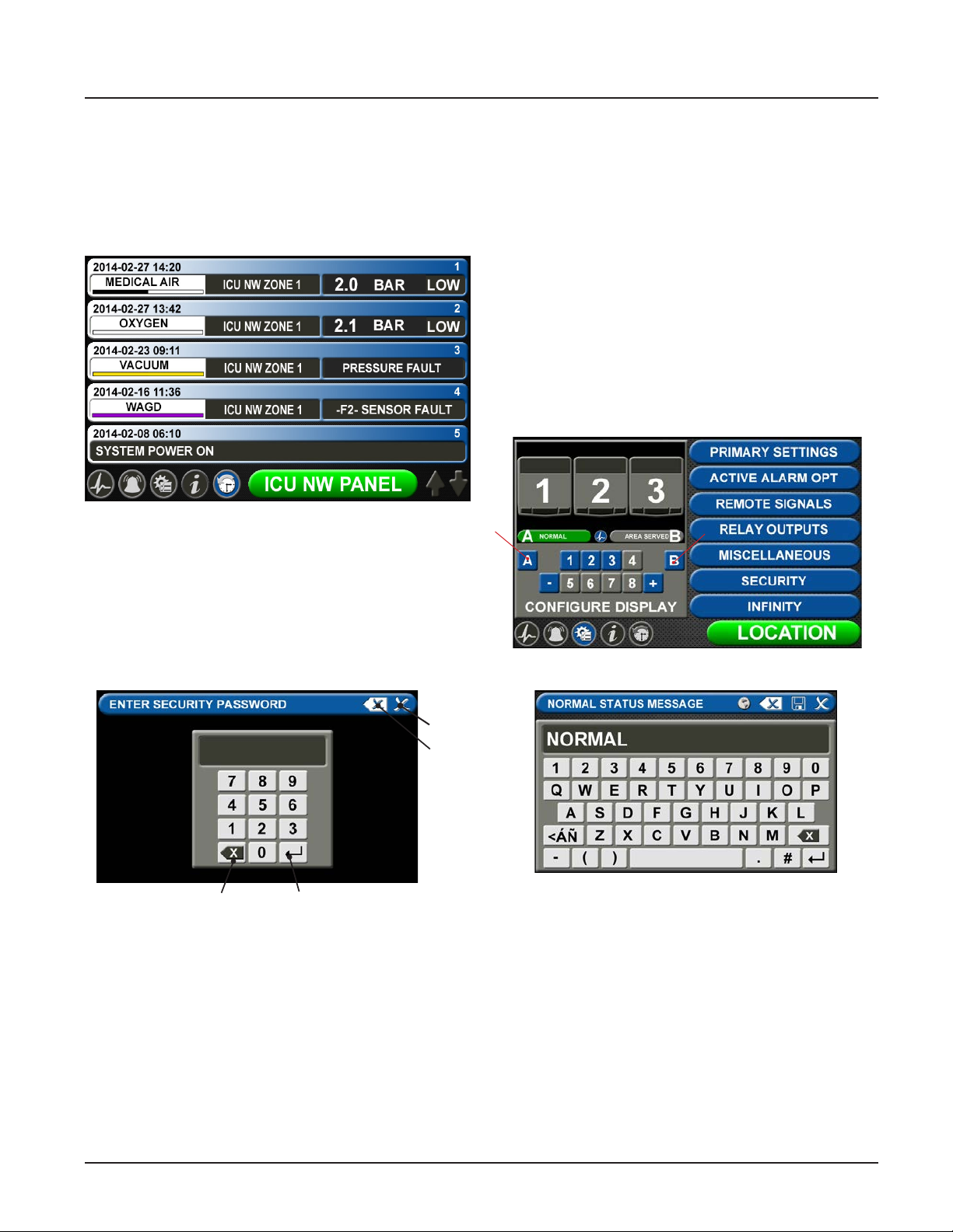
To view up to 100 alarm events on screen, touch the
history button located on the icon toolbar. User can
easily scroll to view the events by touching up/down
arrows in the bottom right corner of the screen.
Figure 15: History Screen
4.2 Alarm Conguration
Type the default password (121212), and touch the
Enter button. You will be prompted to change the password if you have not done so previously.
The CONFIGURATION screen displays.
Normal Status Message/Panel ID
Description
The TotalAlert Innity™ alarm allows for customization
of certain labels and messages.
Normal Status Message
To change the message that is communicated when
the alarm is operating in normal status:
1. Touch the [A] button that is located to the left of
the numeric display (Figure 4.17).
To set up or change the conguration of an alarm,
start on the CONFIGURATION screen. Users are always
prompted to enter the password when accessing this
screen.
Close
Clear all
entered
text
EnterBackspace
Figure 16: Password entry on
Conguration screen
Figure 17: Conguration Screen
Figure 18: Normal Status Message screen
2. Touch the Erase button on the keyboard to delete
the existing message.
3. Enter the new word or message.
4. Touch the Save button.
4-5
4107 9016 60.01
Page 40
TotalAlert Innity™ HTM Medical Gas Notication System
Panel ID Description
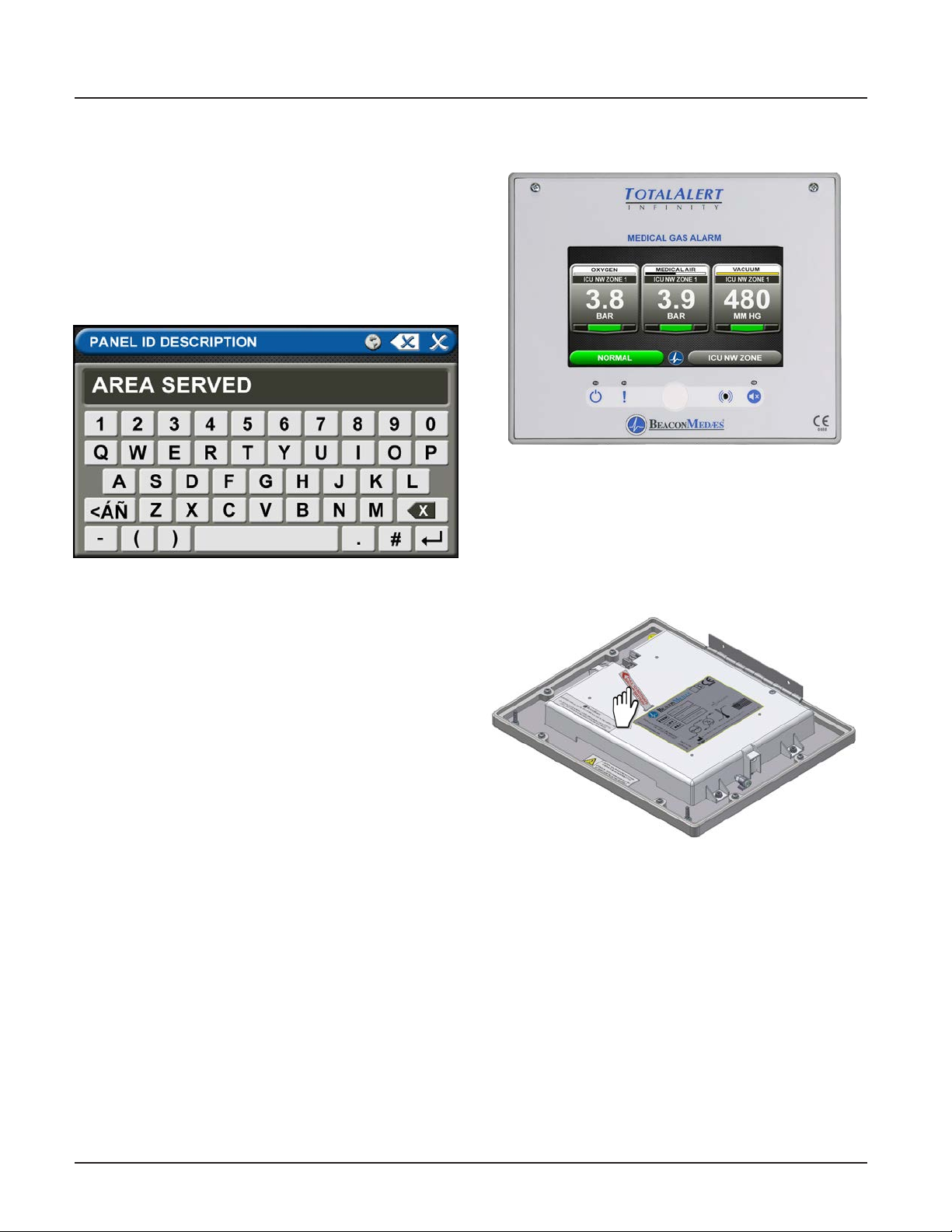
To change the description of the location of the alarm
panel:
1. Touch the [B] button that is located to the right of
the numeric display (Figure 4.17).
2. Touch the Erase button on the keyboard to delete
the existing description.
3. Enter the new description.
4. Touch the Save button.
Figure 19: Panel ID Description screen
4.3 Setting Up an Area Alarm
Figure 20: Area Alarm Main Screen
4.3.1 Initial Setup of an Uncongured
Area Alarm
To begin setup of the alarm, rst pull the battery tab
located on the back of the front panel to activate
battery backup of the alarm.
4107 9016 60.01
Figure 21: Battery Pull Tab
4-6
Page 41
TotalAlert Innity™ HTM Medical Gas Notication System
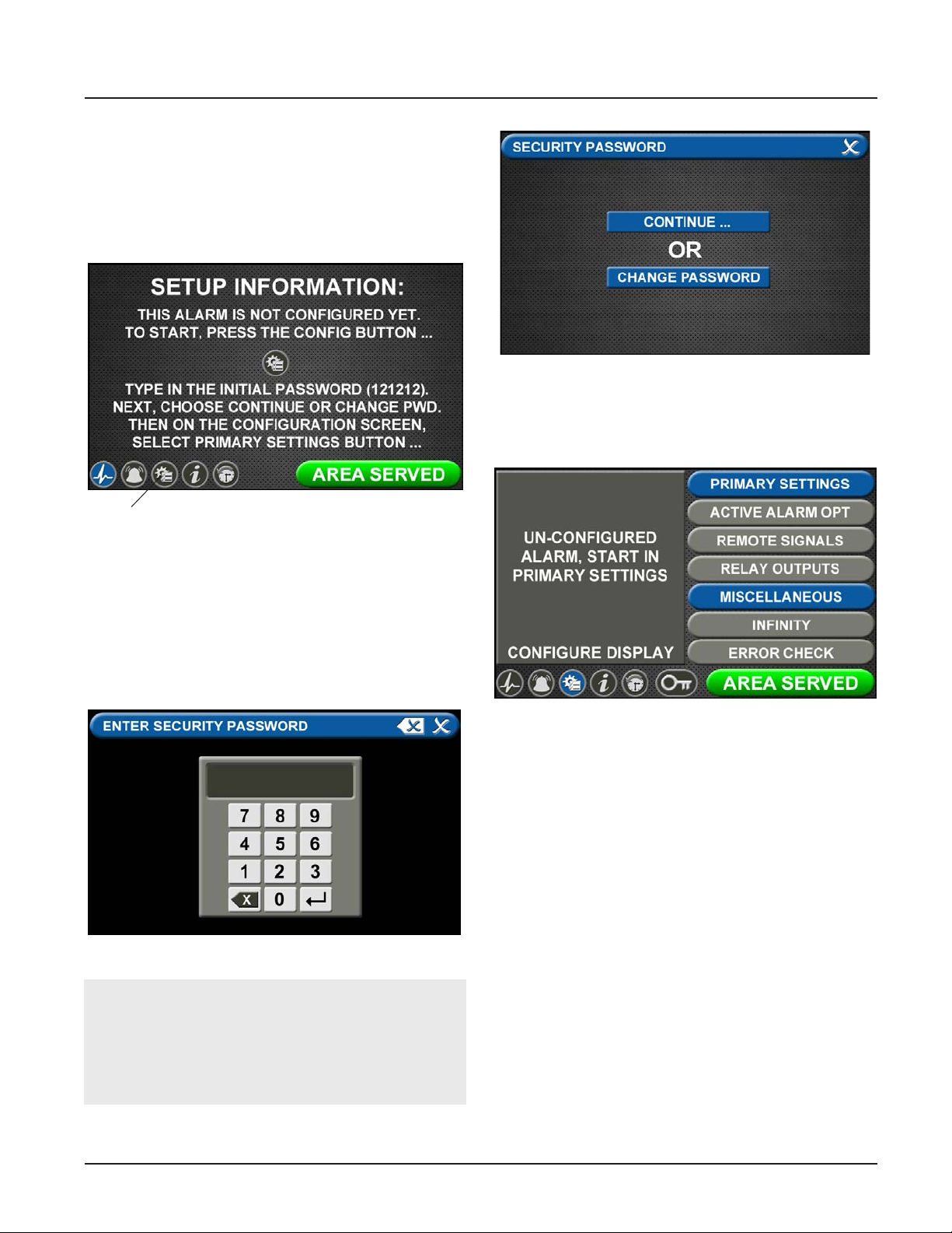
The SETUP INFORMATION screen is the rst screen that
users will see on an uncongured alarm. (The MAIN
screen is the rst screen that users will see on a
congured alarm.)
Password Setup - Uncongured Alarm
• Touch the Conguration button.
Figure 24: Changing the Security Password
• The CONFIGURATION screen will display as
uncongured and ready for setup.
Conguration Button
Figure 22: Setup Information Screen
Entering the Password
The ENTER SECURITY PASSWORD screen appears.
• Enter the security password. (The default password
is 121212.)
• Touch the Enter button.
• Touch Continue to advance to the CONFIGURATION
screen.
Figure 23: Entering the Security Password
Note:
If you would like to change the password, touch
Change Password. Enter a 4-10 digit password, and
touch the Enter button. Conrm the new password.
Touch the X button in the upper right to close the
SECURITY PASSWORD screen.
Figure 25: Uncongured Conguration Screen
4-7
4107 9016 60.01
Page 42
TotalAlert Innity™ HTM Medical Gas Notication System
Primary Settings Tab
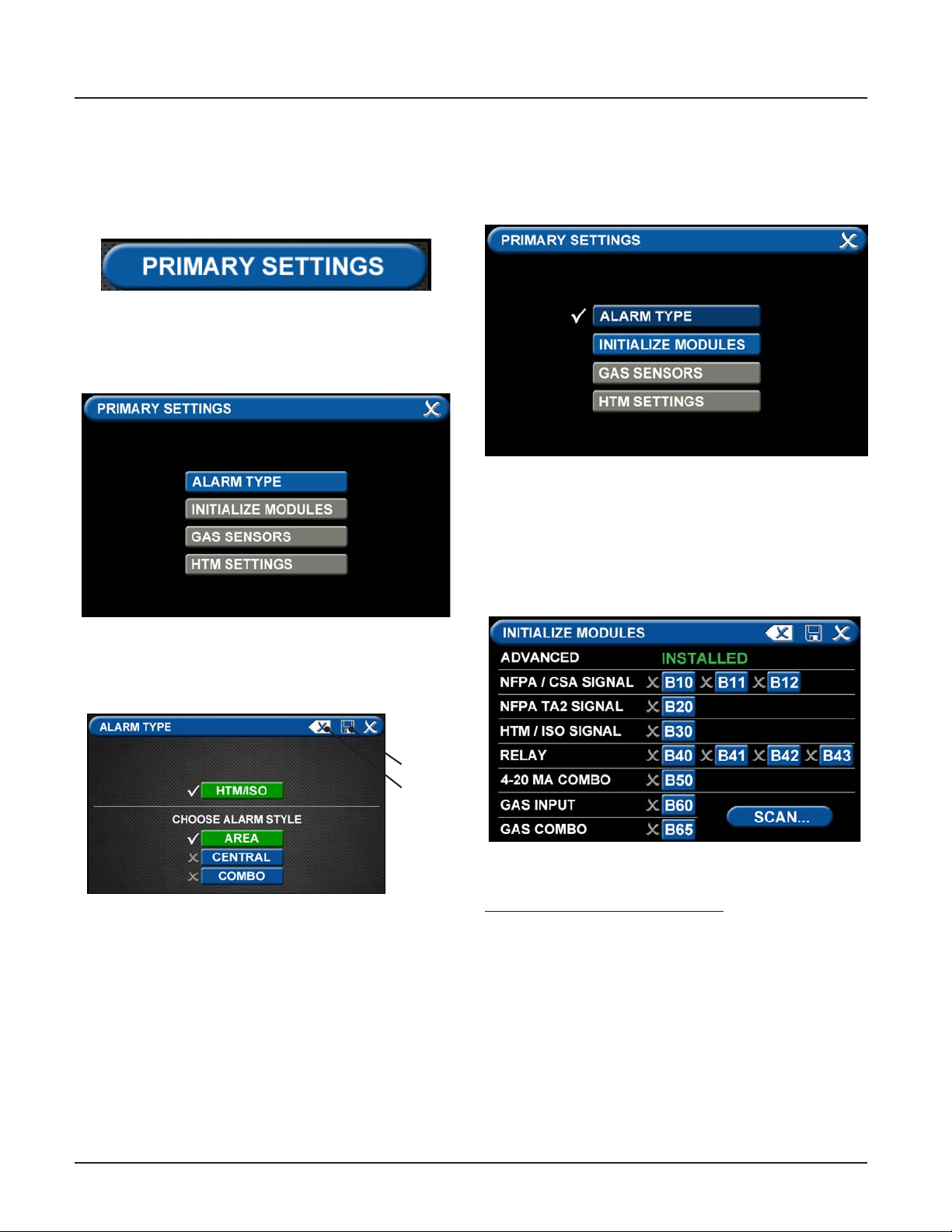
The PRIMARY SETTINGS tab allows you to select the
alarm type, initialize boards, and select gas inputs.
• Touch the PRIMARY SETTINGS tab
Alarm Type Tab
The ALARM TYPE screen denes which type of alarm
will be displayed and drives later setup functions.
Initialize Modules Tab
The PRIMARY SETTINGS screen will now display with
ALARM TYPE checked, INITIALIZE MODULES active, and
the other tabs grayed out.
Figure 28: Initialize Modules Tab
• Touch the INITIALIZE MODULES tab.
The INITIALIZE MODULES screen is used to set up the
boards that are installed. The boards function as the
input/output hardware of the alarm.
Figure 26: Alarm Type Tab
• Touch the ALARM TYPE tab.
• Choose a code style based on code requirements.
Save
Erase
Figure 27: Choosing Code and Alarm Styles
• Touch the AREA tab
• Touch the Save button when you see checks beside
your selections to save the settings and return to
the PRIMARY SETTINGS screen.
Note: To clear your selections, touch the Erase button.
Figure 29: Initialize Modules Screen
At this point, you have two options:
1. Either touch the Scan button to prompt the alarm
to auto ll the screen for you.
OR
2. Complete the screen by selecting the boards
installed in the alarm.
4107 9016 60.01
4-8
Page 43
TotalAlert Innity™ HTM Medical Gas Notication System
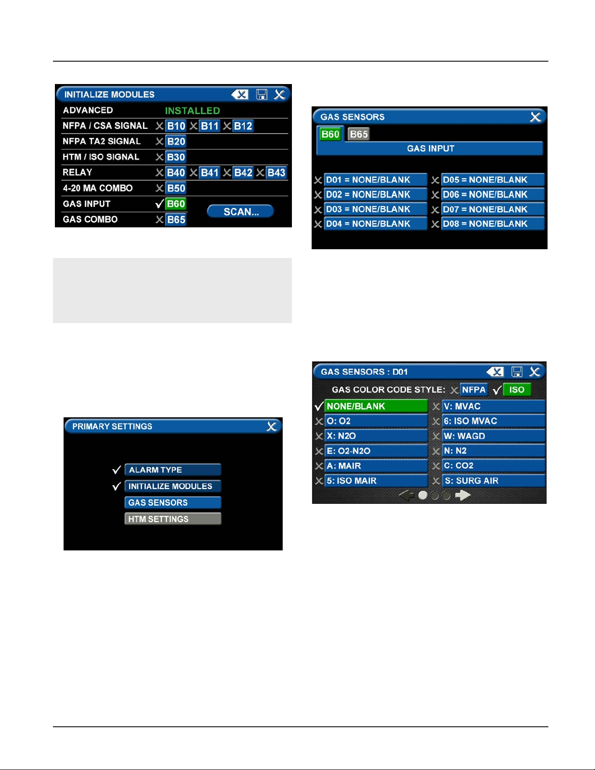
• Touch the GAS SENSORS tab.
Figure 30: B60 board selected
Figure 32: Gas Input Screen
Note:
THE GAS INPUT / B60 board must be selected
during the conguration of an area alarm.
• Touch the Save button when you see checks beside
your selections.
Gas Sensors Tab
The PRIMARY SETTINGS screen will now display with
ALARM TYPE and INITIALIZE MODULES checked, GAS
SENSORS active, and the last tab grayed out.
Users may select up to eight dierent gases on the GAS
INPUT screen. These gases correspond to the digital
gas sensors wired into the GAS INPUT / B60 board (see
section 2.4.2).
• To select the rst gas, touch the D01 = NONE/
BLANK tab.
Figure 31: Gas Sensors Tab
4-9
Figure 33: Gas Sensors Screen
4107 9016 60.01
Page 44
TotalAlert Innity™ HTM Medical Gas Notication System
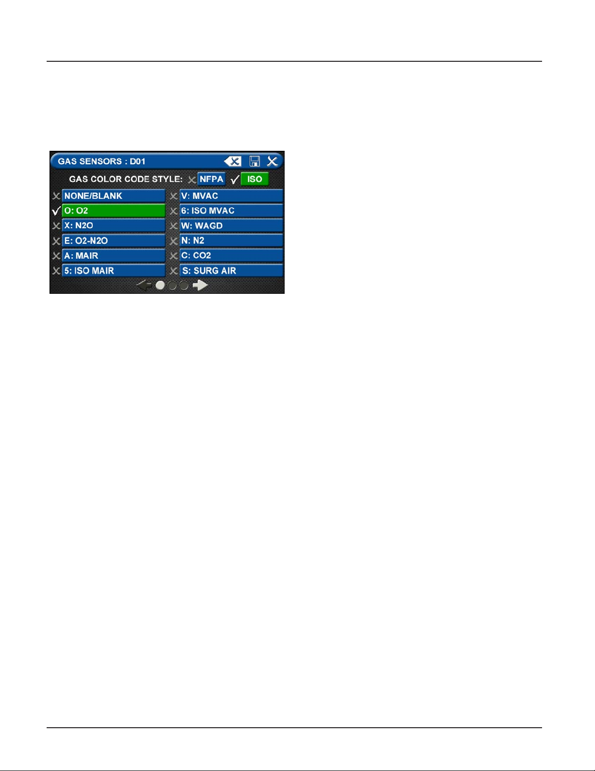
• Touch the right and left arrows at the bottom of
the screen to scroll through additional gas choices,
including options to create custom mixes. Select
the gas that is wired into the D01 input on the GAS
INPUT / B60 board.
Figure 34: Gas Choices
• Touch the Save button when you see a check
beside your selection.
• (If an alarm sounds, press the Mute button on the
panel under the screen and continue with setup.)
• Repeat to add additional gases.
• Touch the X button in the upper right to close the
GAS SENSORS screen and return to the PRIMARY
SETTINGS screen. The alarm will retain your information.
• Touch the X button in the upper right to close the
PRIMARY SETTINGS screen. The alarm will retain
your information.
4107 9016 60.01
4-10
Page 45
TotalAlert Innity™ HTM Medical Gas Notication System
4.3.2 Conguring Gas ID Badges
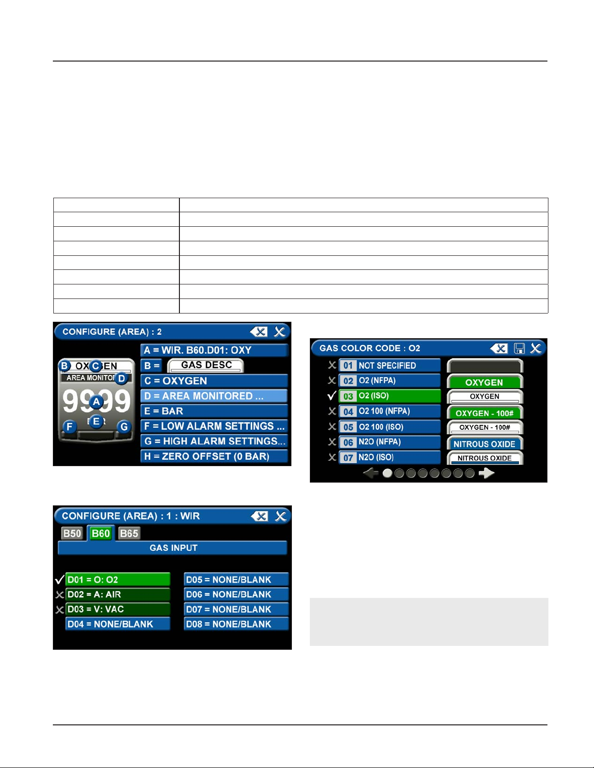
The TotalAlert Innity™ Area alarm is designed to allow
conguration of eight gas badges using the B60 board.
To congure the rst badge to custom settings, touch
the [1] button in the numeric display of the conguration screen (Figure 4.17).
Eight tabs are used for conguration (Figure 4.34). Tabs
are listed in alphabetical order
A = [GAS INPUT] To change which wired input should be shown on the badge
B = GAS DESC To change color codes based on standard and country
C = [GAS NAME] To label the gas
D = AREA MONITORED To edit the location label for the specic gas
E = [UNITS OF MEASURE] To change the displayed unit of measure for the pressure/vacuum
F = LOW ALARM SETTINGS To adjust the value that should indicate that the pressure is low
G = HIGH ALARM SETTINGS To adjust the value that should indicate that the pressure is high
H = ZERO OFFSET To make small adjustments to the displayed pressure based on user preference
B = Gas Desc Tab
Figure 35: Conguring Gas Badges
A = [Gas Input] Tab
Figure 36: Gas Input Tab
To change which wired sensor should be displayed on
that badge:
1. Touch the tab for the appropriate wired gas sensor.
2. Touch the Save button to close the screen.
Figure 37: Gas Desc Tab
To change color codes based on your standard and
country:
1. Scroll through the codes using the right and left
arrows at the bottom of the screen.
2. Touch the tab for the appropriate code.
3. Touch the Save button when you see a check
beside your selection.
NOTE:
If the alarm default is correct, touch the X button
in the upper right to close the screen.
4-11
4107 9016 60.01
Page 46
TotalAlert Innity™ HTM Medical Gas Notication System
C = [Gas Name] Tab
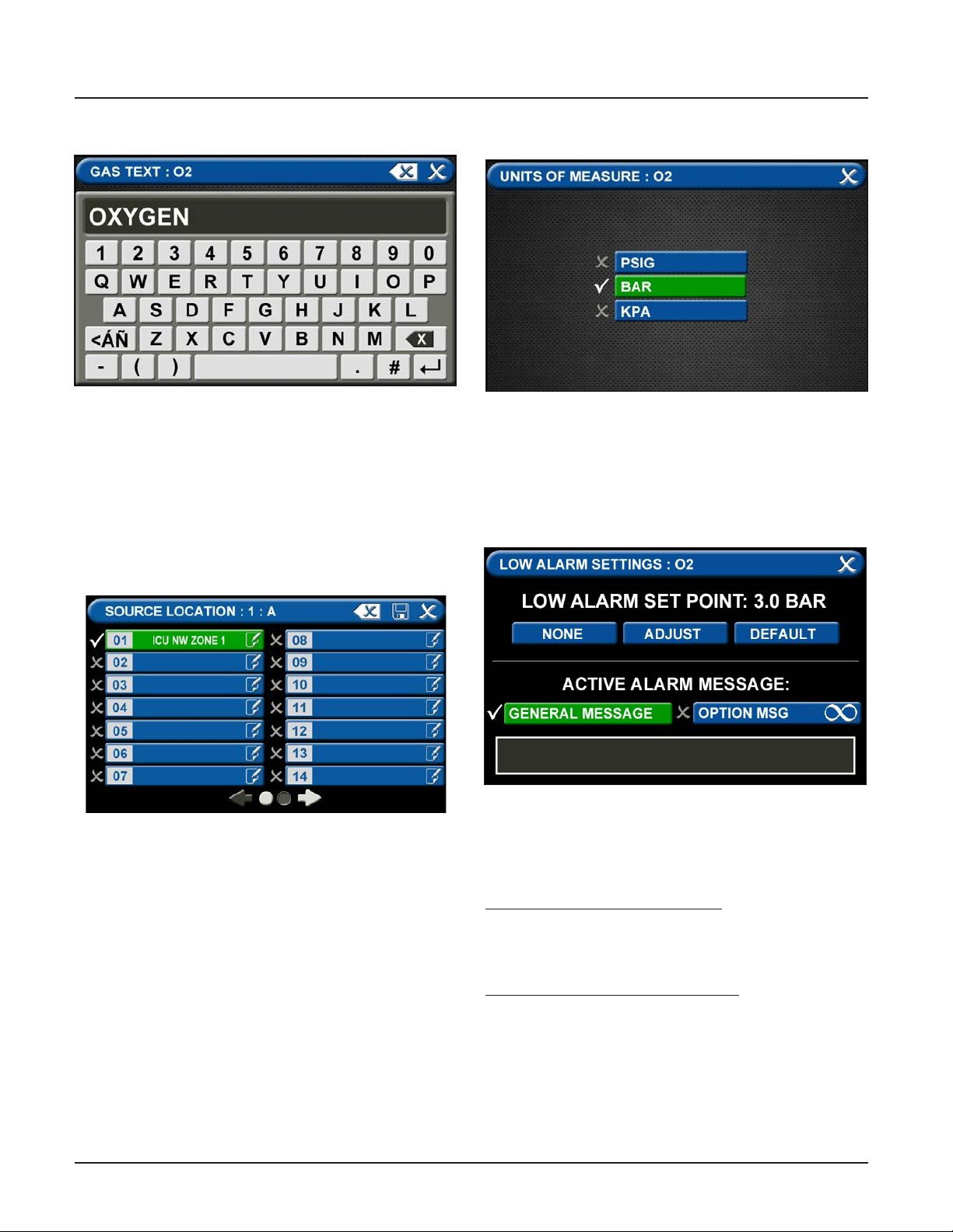
Figure 38: Gas Text Screen
• Touch the Erase button on the keyboard to delete
the gas name.
• Enter the new gas name. Touch the [<ÁÑ] to toggle
to symbols and extended Latin Characters. Touch
the [1AZ] key to toggle back to letters and numbers.
• Touch the Save button
D = Area Monitored Tab
E = [Units of Measure] Tab
Figure 40: Units of Measure Tab
To change the unit of measure:
1. Touch the tab for the appropriate unit of measure.
2. Touch the Save button to close the screen.
F = Low Alarm Settings Tab
Figure 39: Area Monitored Tab
To add locations to be monitored:
1. Touch an unused location tab.
2. Using the keyboard, enter the name of the location
that you would like to monitor (e.g., ROOM 1). Enter
multiple locations as needed (e.g., Room 1, Room
5).
3. A check appears when the location is selected, the
save button has to be pressed if the selection is
new.
To edit the location information, touch the Pencil
button.
4107 9016 60.01
Figure 41: Low Alarm Settings Tab
You can remove the low alarm set point or customize
the low alarm set point.
To remove the low alarm set point:
1. Touch the NONE tab.
2. Touch the check on the CONFIRM SETTINGS
CHANGE screen.
To customize the low alarm set point:
1. Touch the ADJUST tab.
2. Enter the new set point.
3. Touch the Save button.
4-12
Page 47
TotalAlert Innity™ HTM Medical Gas Notication System
Active Alarm Instruction:
To set facility instructions for active alarms, touch
either the GENERAL MESSAGE or OPTION MSG tab.
The alarm defaults to GENERAL MESSAGE. See Section 4.6 for how to set up custom instructions.
G = High Alarm Settings Tab
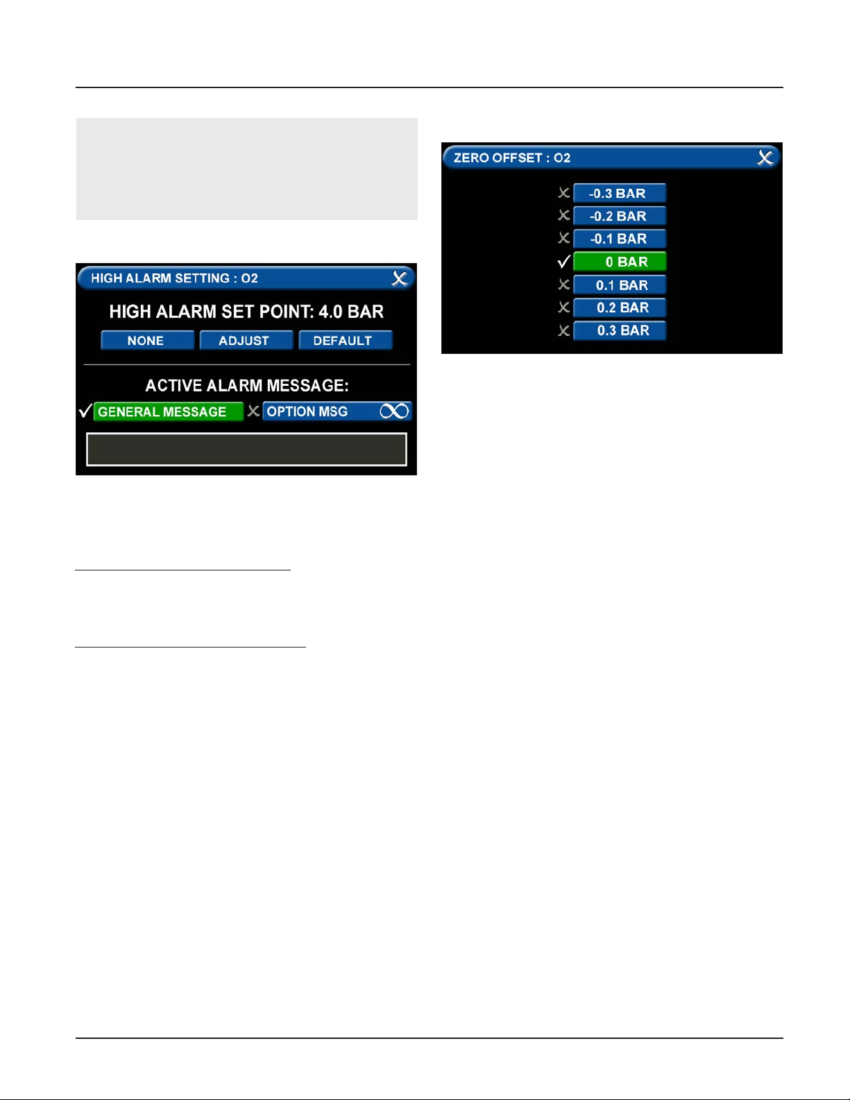
Figure 42: High Alarm Settings Tab
You can remove the high alarm set point or customize
the high alarm set point.
To remove the high alarm set point:
1. Touch the NONE tab.
2. Touch the check on the CONFIRM SETTINGS
CHANGE screen.
To customize the high alarm set point:
1. Touch the ADJUST tab.
2. Enter the new set point.
3. Touch the Save button.
H = Zero Oset Tab
Figure 43: Zero Oset Tab
In some cases, facility dial gauges may show slightly
dierent readings than the TotalAlert Innity™ alarm
(e.g., 3.2 BAR versus 3.0 BAR). To match the
TotalAlert Innity™ alarm exactly to a facility dial gauge:
1. Select the oset amount.
2. Touch the Save button to close the screen.
Conguring Additional Gas Badges
Congure additional gas badges by touching the
number on the main conguration screen that
corresponds with the gas badge and repeating the
steps listed above.
4-13
4107 9016 60.01
Page 48
TotalAlert Innity™ HTM Medical Gas Notication System
4.4 Setting Up a Central Alarm
The central alarm monitors whether source equipment
is working properly.
The information for the signals connected in the eld
needs to be entered into the alarm using the touch
screen interface.
Figure 44: Central Alarm Main Screen
The SETUP INFORMATION screen is the rst screen that
users will see on an uncongured alarm.
(The MAIN screen is the rst screen that users will see
on a congured alarm).
• Touch the Conguration button.
Conguration
Button
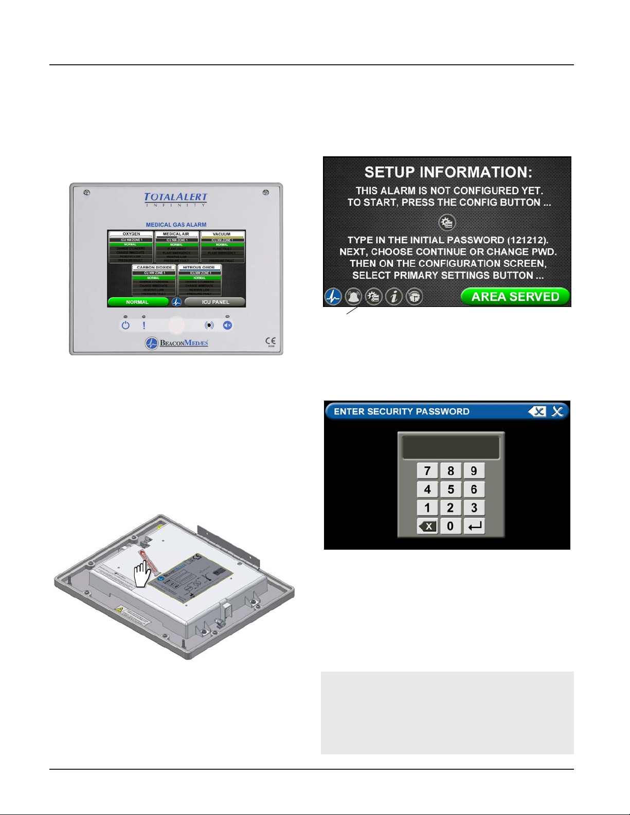
Figure 46: Setup Information Screen
Entering the Password
The ENTER SECURITY PASSWORD screen appears.
To set up or change the conguration of an alarm,
follow the steps outlined under Alarm Type Tab.
4.4.1 Initial Setup of an Uncongured
Central Alarm
To begin setup of the alarm, rst pull the battery tab
located on the back of the front panel to activate
battery backup of the alarm.
Figure 45: Battery Pull Tab
Figure 47: Entering the Security Password
• Enter the security password. (The default password
is 121212.)
• Touch the Enter button.
• Touch Continue to advance to the CONFIGURATION
screen.
• The CONFIGURATION screen will display as
uncongured and ready for setup
Note:
If you would like to change the password, touch
Change Password. Enter a 4-10 digit password, and
touch the Enter button. Conrm the new password.
Touch the X button in the upper right to close the
SECURITY PASSWORD screen.
4107 9016 60.01
4-14
Page 49
TotalAlert Innity™ HTM Medical Gas Notication System
Figure 50: Choosing Code and Alarm Styles
Save
Erase
Figure 48: Changing the Security Password
Primary Settings Tab
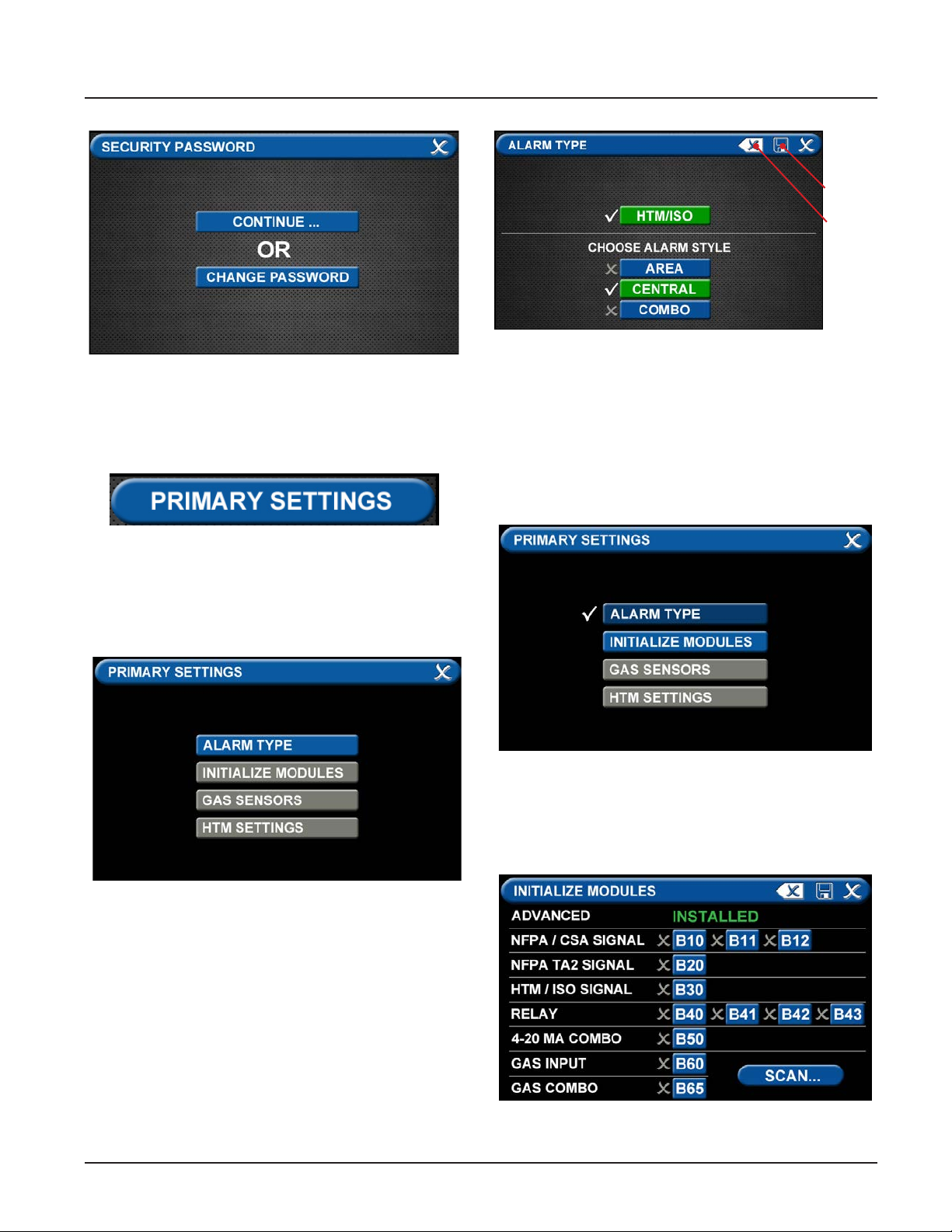
The PRIMARY SETTINGS tab allows you to select the
alarm type and initialize boards.
• Touch the PRIMARY SETTINGS tab.
Alarm Type Tab
The ALARM TYPE screen denes which type of alarm
will be displayed and drives later setup functions.
• Touch the ALARM TYPE tab.
• Touch the Save button when you see checks beside
your selections to close the screen and return to
the PRIMARY SETTINGS screen.
Note: To clear your selections, touch the Erase button.
Initialize Modules Tab
The PRIMARY SETTINGS screen will now display with
ALARM TYPE checked and INITIALIZE MODULES active.
Figure 51: Initialize Modules Tab
• Touch the INITIALIZE MODULES tab.
The INITIALIZE MODULES screen is used to set up the
boards that are installed. The boards function as the
input/output hardware of the alarm.
Figure 49: Alarm Type Tab
• Choose a code style based on code requirements.
• Touch the Central tab.
4-15
Figure 52: Initialize Modules Screen
4107 9016 60.01
Page 50
TotalAlert Innity™ HTM Medical Gas Notication System
At this point, you have two options:
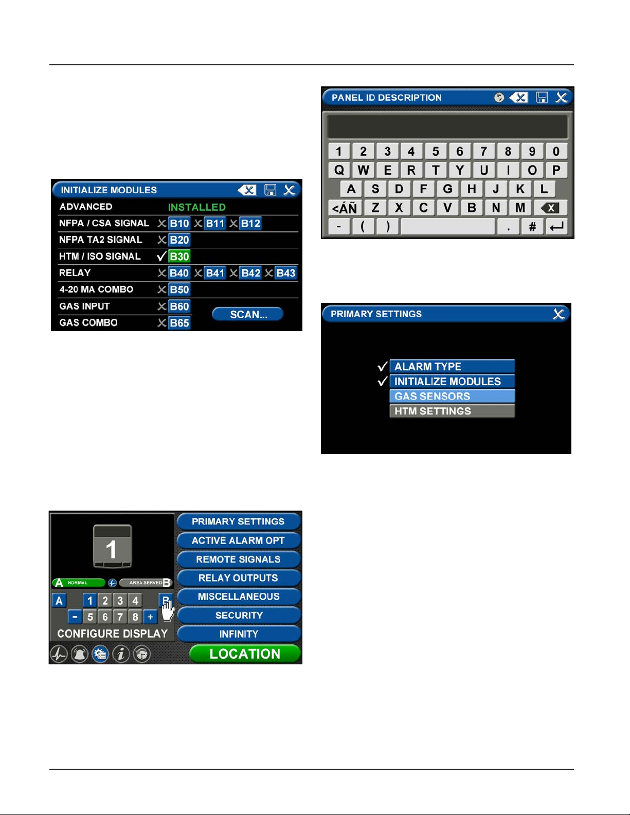
1. Either touch the Scan button to prompt the alarm
to autoll the screen for you.
OR
2. Complete the screen by selecting the boards
installed in the alarm.
Figure 55: Entering the Location
Enter area served and touch save to return to the
conguration screen. Touch the PRIMARY SETTINGS
tab.
Figure 53: B30 board selected
• Touch the Save button when you see checks beside
your selections.
• Touch the X button in the upper right to close and
return to the CONFIGURATION screen.
The PRIMARY SETTINGS screen will now display with
ALARM TYPE and INITIALIZE MODULES highlighted and
checked and the other tabs grayed out.
• Touch the X button in the upper right to close and
return to the CONFIGURATION screen.
Setting up the Location
Figure 56: Primary Settings Screen
The PRIMARY SETTINGS screen will display with ALARM
TYPE and INITIALIZE MODULES checked, GAS SENSORS
active, and the last tab grayed out.
Touch the GAS SENSORS tab.
Figure 54: Location Setup
Touch B to set the LOCATION text.
4107 9016 60.01
4-16
Page 51
TotalAlert Innity™ HTM Medical Gas Notication System
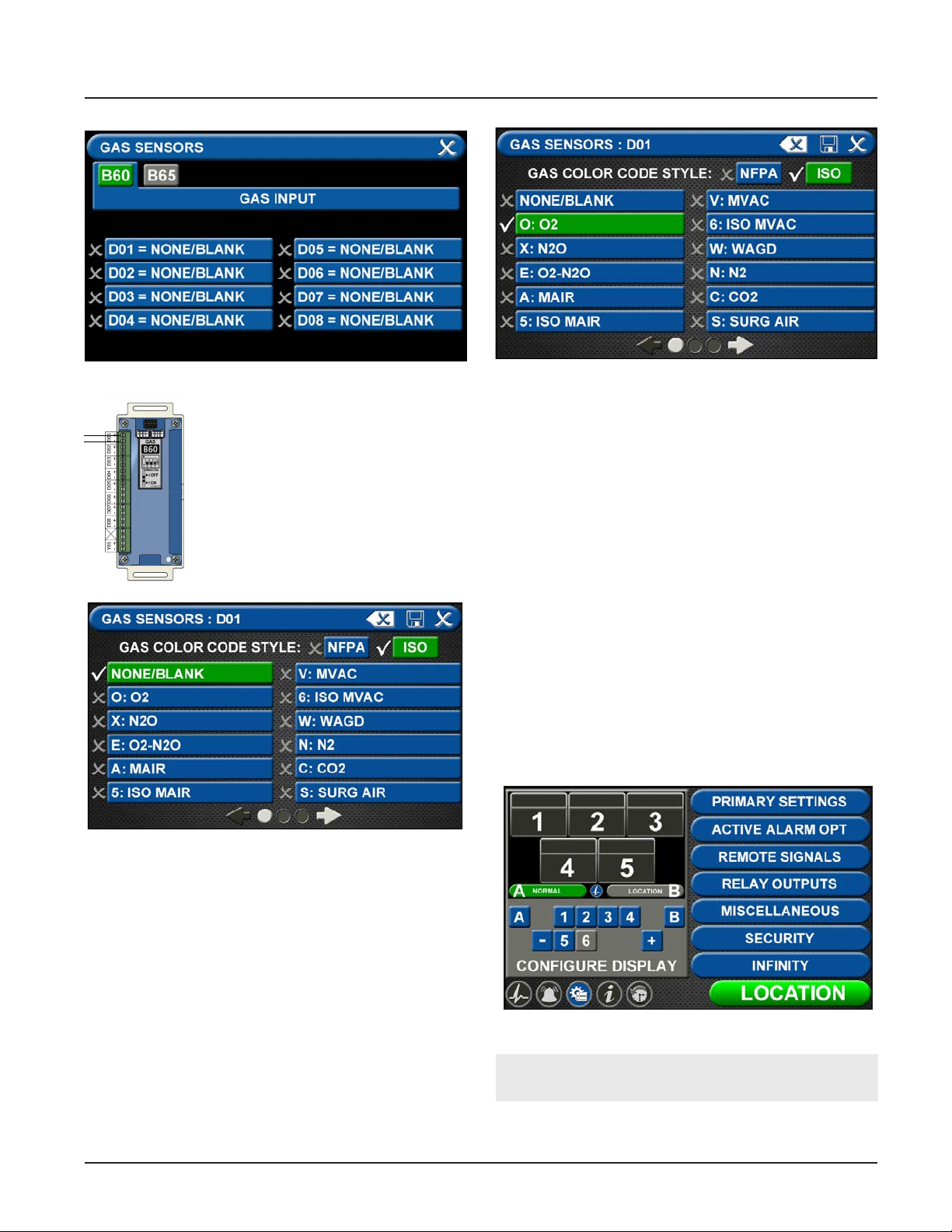
Figure 57: Gas Input Screen
Up to eight dierent gases may be
selected on the GAS INPUT screen.
These gases correspond to the digital
gas sensors wired into the GAS INPUT
/ B60 board. To select the rst gas,
touch the D01 = NONE/BLANK tab.
Figure 59: Gas Sensors Selection
Touch the Save button when you see a check beside
your selection (If an alarm sounds, press the Mute
button on the panel under the screen and continue
with setup).
Repeat starting at step 4.57 to add additional gases.
Touch the X button in the upper right to close the GAS
SENSORS screen and return to the PRIMARY SETTINGS
screen. Touch the X button in the upper right to close
the PRIMARY SETTINGS screen. The alarm will retain
your information.
4.4.2 Conguring Source Badges
The TotalAlert Innity™ central alarm is designed to
allow the setup and monitoring of 6 source badges.
Forty source locations with up to 8 source signal inputs
for each location can be congured (maximum of 20
locations per gas type).
To congure alarm points in the rst badge, touch the
Figure 58: Gas Sensors Screen
Select the gas that is wired into the D01 input on the
GAS INPUT / B60 board. Touch the right and left arrows
at the bottom of the screen to scroll through additional
gas choices, including options to create custom mixes.
Figure 60: Conguration Screen
Note:
Maximum wired input signals allowed is 20.
4-17
4107 9016 60.01
Page 52
TotalAlert Innity™ HTM Medical Gas Notication System
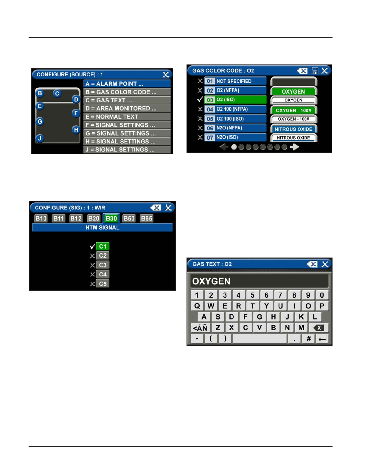
(1) botton in the numeric display (Figure 4.60).
Figure 61: Congure Source Screen
A = Alarm Point
Touch the ALARM POINT tab to select the
proper HTM Signal Channel.
B = Gas Color Code Tab
Figure 63: Gas Color Code Tab
To select the color code for the appropriate gas based
on your standard and country:
1. Touch the B = GAS COLOR CODE tab (Figure 4.63)
2. Scroll through the gas types using the right and left
arrows at the bottom of the screen.
3. Touch the tab for the appropriate code, or select a
“custom” tab to create a unique source badge.
4. Touch the Save button when you see a check
beside your selection. This will automatically ll in
tabs C-J with default values for the gas selected. If
changes are needed follow the next steps below.
C = Gas Text Tab
Figure 62: HTM Signal Channel
Conguration Screen
To identify the location where the wires are landed:
1. Touch the tab for the appropriate board and
terminal block. (C1, C2, C3, C4, C5)
2. Touch the Save button when you see a check
beside your selection.
4107 9016 60.01
Figure 64: Gas Text Keyboard
Using the keyboard, enter the name of the area. To
change the name of the gas:
1. Touch the C = [GAS TEXT] tab.
2. Touch the Erase button on the keyboard to delete
the gas name.
3. Enter the new gas name. Touch the [<ÁÑ] to toggle
to symbols. Touch the [1AZ] key to toggle back to
letters and numbers.
4. Touch the Save button.
4-18
Page 53
TotalAlert Innity™ HTM Medical Gas Notication System
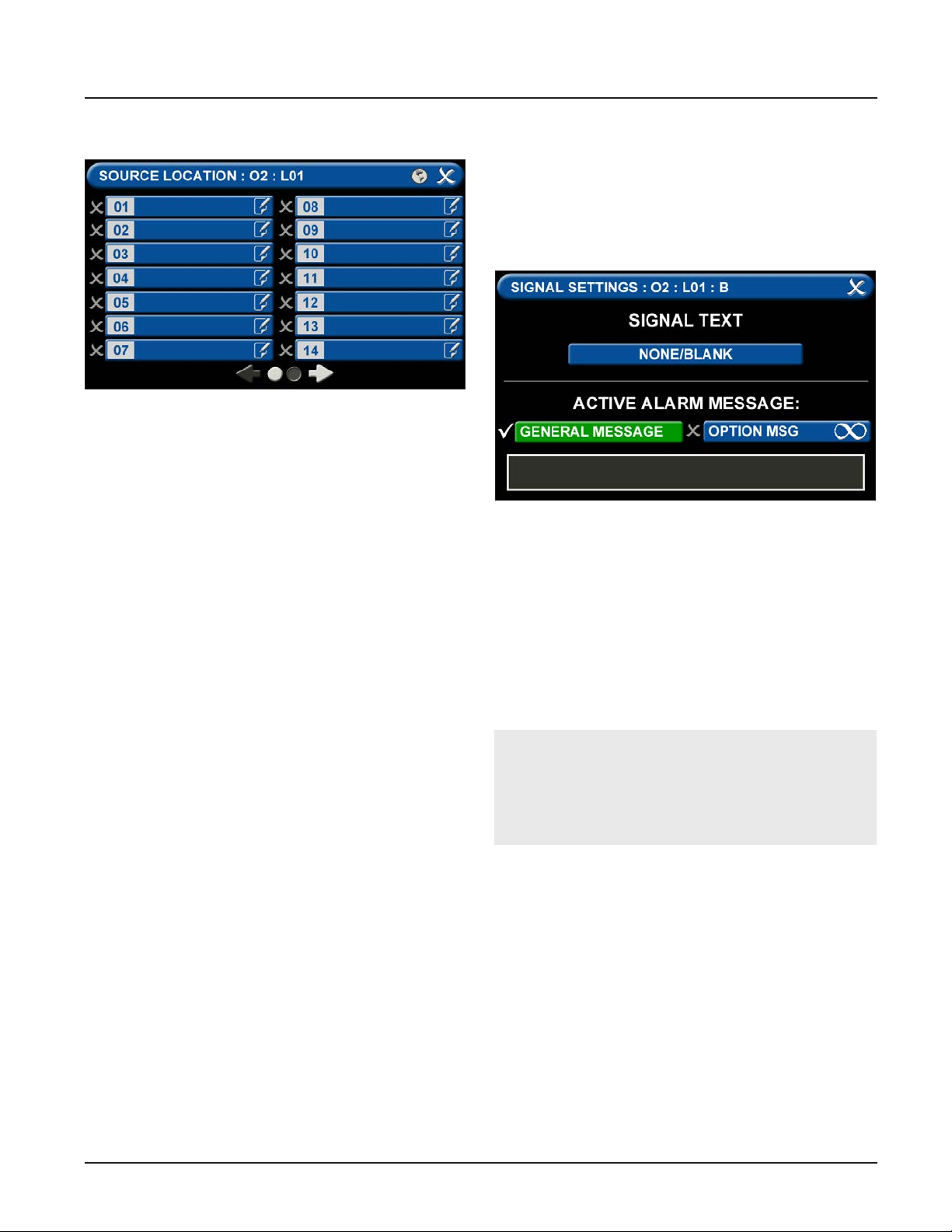
D = Area Monitored
Figure 65: Congure Channels
Touch the D = (Area Monitored) Tab
On the SOURCE LOCATION screen:
1. Touch the 01 tab. 1.
2. Using the keyboard, enter the name of the location
for the source equipment being monitored (e.g.,
ROOM 1). Enter multiple locations as needed (e.g.,
Manifold Room, Roof Top, Source Room).
3. Touch the Save button. A check appears when the
location is saved. Note: To edit the location, touch
the Pencil button.
4. Touch the X button to close and return to the
CONFIGURE (SOURCE) screen.
Each Plant (Source) badge has room for 5 signal inputs
(E-J) (Figure 4.61). The rst tab E is used to show the
alarm in “Normal” condition. The (F-H) inputs are used
for warning inputs such as “Change Cylinders” and ash
yellow when active. The last input (J) is used for the
fault condition and ashes red when in fault mode.
To select source signal input text:
Figure 66: Signal Settings Screen
1. Scroll through the options using the right and left
arrows at the bottom of the screen.
2. Touch the tab for the appropriate option, or select
a blank to create a custom alarm.
3. Touch the Save button when you see a check
beside your selection to close and return to the
SIGNAL SETTINGS screen.
4. Touch the X button in the upper right to close and
return to the CONFIGURE (SOURCE) screen.
Active Alarm Instruction:
To set facility instructions for active alarms, touch
either the GENERAL MESSAGE or OPTION MSG tab.
The alarm defaults to GENERAL MESSAGE. See
Section 4.6 for how to set up custom instructions.
4-19
4107 9016 60.01
Page 54
TotalAlert Innity™ HTM Medical Gas Notication System
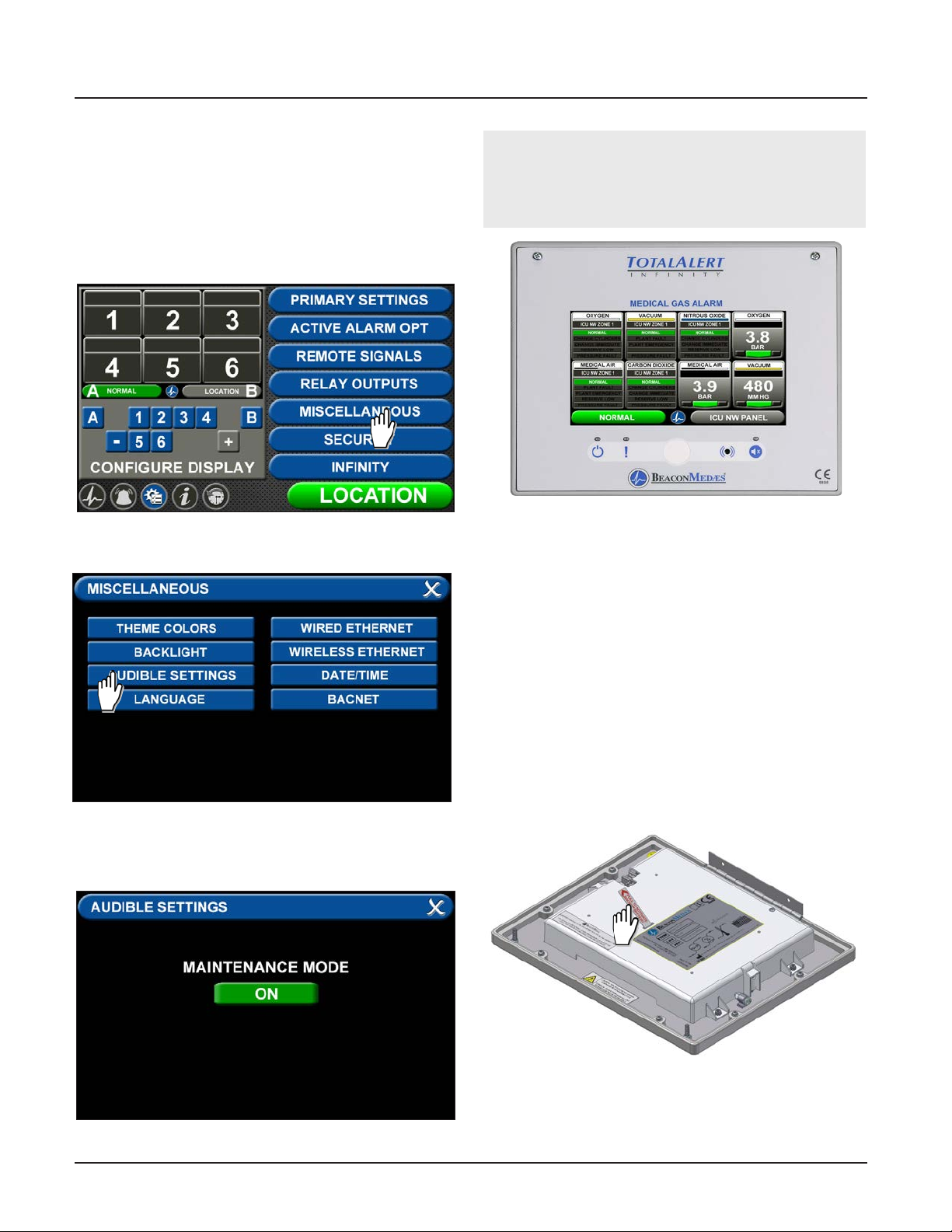
4.4.3 Maintenance Mode Setup
To ensure the audible warning does not sound while
setting up the alarm, the MAINTENANCE MUTE function
can be activated.
Touch the MISCELLANEOUS tab in the conguration
menu.
Figure 67: Miscellaneous Tab
Touch the AUDIBLE SETTINGS tab.
NOTE:
See the end of this section for information on the
Miscellaneous Tab. See Section 4.6 for information
on the Active Alarm Opt Tab.
Figure 70: Combination Alarm Main Screen
4.5 Setting up a Combination
Alarm
The TotalAlert Innity™ combination alarm combines
the functionality of a Area alarm and a central alarm. It
monitors two things:
• Gases and their pressures.
• Source equipment.
Figure 68: Audible Settings Tab
Press the tab to turn maintenance mode on. Exit the
screens to return to the conguration screen.
Figure 69: Maintenance Mode ON
4.5.1 Initial Setup of an Uncongured
Combination Alarm
To begin setup of the alarm, rst pull the battery tab
located on the back of the front panel to activate
battery backup of the alarm.
Figure 71: Battery Pull Tab
4107 9016 60.01
4-20
Page 55
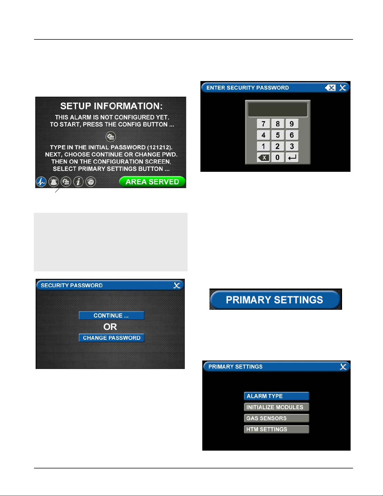
TotalAlert Innity™ HTM Medical Gas Notication System
The SETUP INFORMATION screen is the rst screen that
users will see on an uncongured alarm.
(The MAIN screen is the rst screen that users will see
on a congured alarm).
• Touch the Conguration button.
Conguration Button
Figure 72: Setup Information Screen
NOTE:
If you would like to change the password, touch
Change Password. Enter a 4-10 digit password,
and touch the Enter button. Conrm the new
password. Touch the X button in the upper right to
close the SECURITY PASSWORD screen.
Entering the Password
The ENTER SECURITY PASSWORD screen appears.
Figure 74: Entering the Security Password
Enter the security password. (The default password is
121212.)
• Touch the Enter button.
• Touch Continue to advance to the
CONFIGURATION screen.
• The CONFIGURATION screen will display as
uncongured and ready for setup.
Primary Settings Tab
The PRIMARY SETTINGS tab allows you to select the
alarm type and initialize boards.
Figure 73: Changing the Security Password
• Touch the PRIMARY SETTINGS tab.
• Alarm Type Tab
The ALARM TYPE screen denes which type of alarm
will be displayed and drives later setup functions.
Figure 75: Alarm Type Tab
4-21
4107 9016 60.01
Page 56
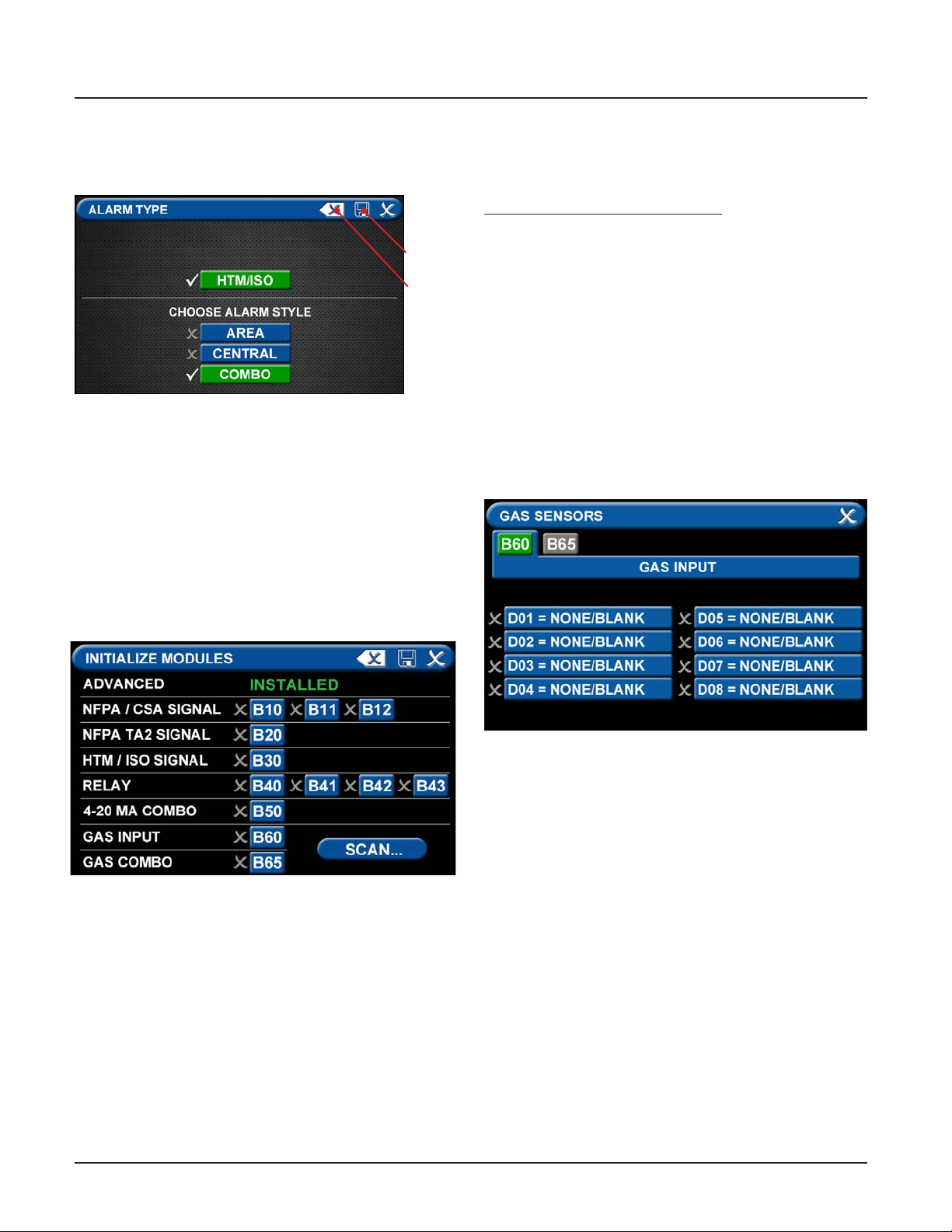
TotalAlert Innity™ HTM Medical Gas Notication System
• Touch the ALARM TYPE tab.
• Choose a code style based on code requirements.
• Touch the COMBO tab.
Save
Erase
Figure 76: Choosing Code and Alarm Styles
• Once the desired tabs are selected, touch the Save
button to save the selection and go back to the
PRIMARY SETTINGS screen.
Note: To clear your selections, touch the Erase button.
• Initialize Modules Tab
The PRIMARY SETTINGS screen will now display with
ALARM TYPE checked and INITIALIZE MODULES active.
• Touch the INITIALIZE MODULES tab.
The INITIALIZE MODULES screen is used to set up the
boards that are installed. The boards function as the
input/output hardware of the alarm.
At this point, you have two options:
1. Either touch the Scan button to prompt the alarm
to autoll the screen for you.
OR
2. Complete the screen by selecting the boards
installed in the alarm.
Touch the Save button when you see checks beside
your selections.
Gas Sensors Tab
The PRIMARY SETTINGS screen will now display with
ALARM TYPE and INITIALIZE MODULES checked, GAS
SENSORS active, and the last tab grayed out.
• Touch the GAS SENSORS tab
Figure 77: Initialize Modules Screen
4107 9016 60.01
Figure 78: B60 Gas Input Screen
4-22
Page 57
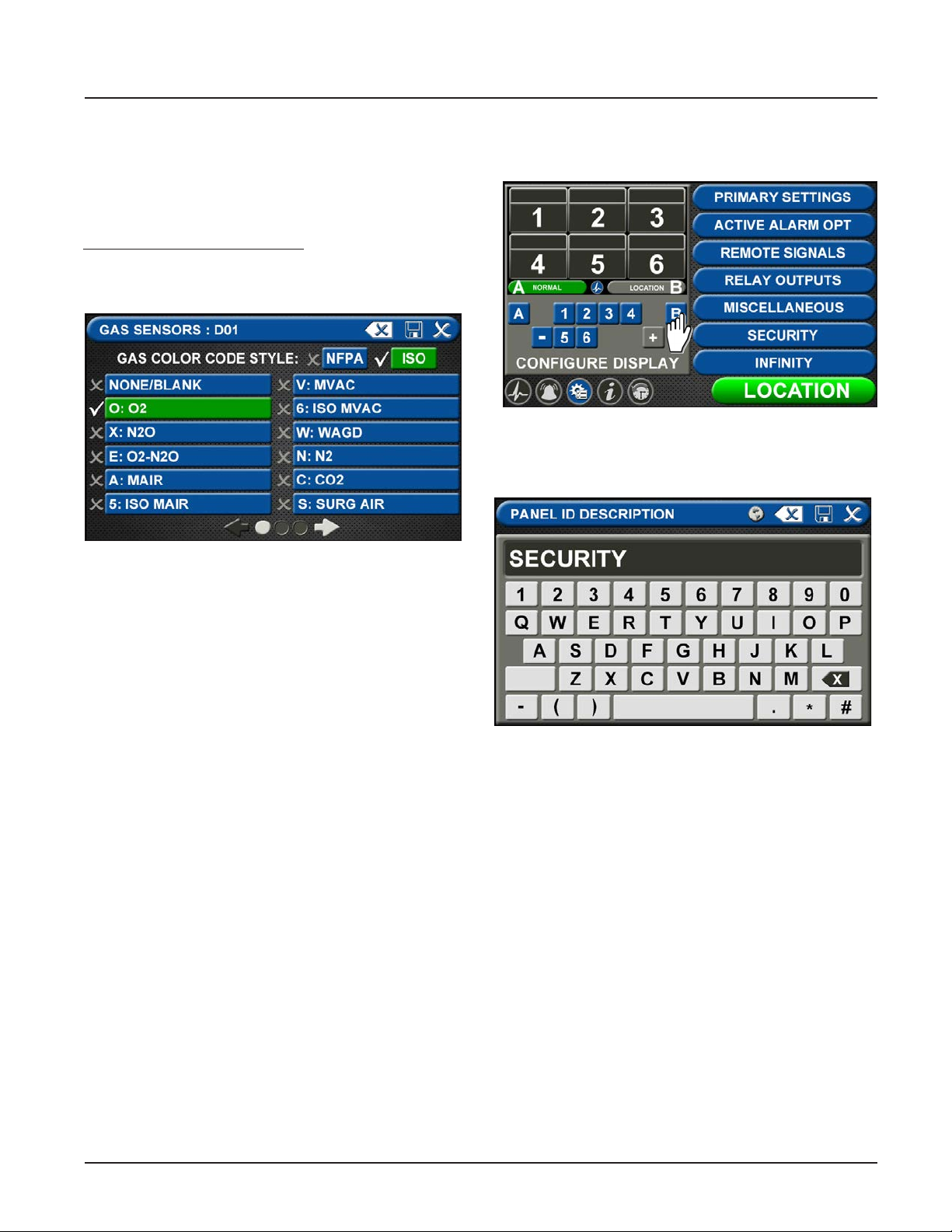
TotalAlert Innity™ HTM Medical Gas Notication System
B60 Board
Users may select up to six dierent gases on the GAS
INPUT screen. These gases correspond to the pressure
sensors wired into the GAS INPUT / B60 board or the
Gas Combination / B65 board.
Note: This setup accommodates:
• Eight badges, with up to 5 central badges or 7 area
badges.
Figure 79: Gas Choices
To select the rst gas, touch the D01=NONE/BLANK tab.
• Touch the right and left arrows at the bottom of
the screen to scroll through additional gas choices.
Select the gas that is wired into the D01 input on
the GAS INPUT / B60 board.
• Touch the Save button when you see a check
beside your selection. (If an alarm sounds, press
the Mute button on the panel under the screen and
continue with setup.)
• Repeat to add additional gases.
• Touch the X button in the upper right to close the
GAS SENSORS screen and return to the PRIMARY
SETTINGS screen. The alarm will retain your
information.
Setting up the Location
Touch B to set the LOCATION text.
Figure 80: Location Setup
Enter the central alarm location and touch save to
return to the conguration screen.
Figure 81: Entering the Location
4-23
4107 9016 60.01
Page 58
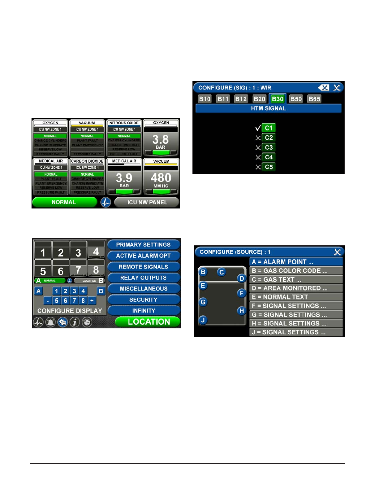
TotalAlert Innity™ HTM Medical Gas Notication System
4.5.2 Conguring Source Badges
The TotalAlert Innity™ combination alarm is designed
to allow the conguration of ten source badges. Twenty
locations with up to eight source signals each can be
tied to each source badge.
To congure alarm points in a central badge, touch the
[1] button on the conguration screen (Figure 4.83).
Figure 82: Combination Alarm Screen
• Congure (Source) Badge
A = Alarm Point
Touch the ALARM POINT tab to select the
proper HTM Signal.
Figure 84: HTM Signal Conguration Screen
To identify the location where the wires are landed:
1. Touch the tab for the appropriate board and
terminal block. (C1, C2, C3, C4, C5)
2. Touch the Save button when you see a check
beside your selection.
B = Gas Color Code Tab
Figure 83: Congure Source Screen
4107 9016 60.01
Figure 85: Conguration Screen
To select the color code for the appropriate gas based
on your standard and country:
1. Touch the B = GAS COLOR CODE tab (Figure 4.85)
2. Scroll through the gas types using the right and left
arrows at the bottom of the screen.
3. Touch the tab for the appropriate code, or select a
“custom” tab to create a unique source badge.
4. Touch the Save button when you see a check beside your selection.
4-24
Page 59
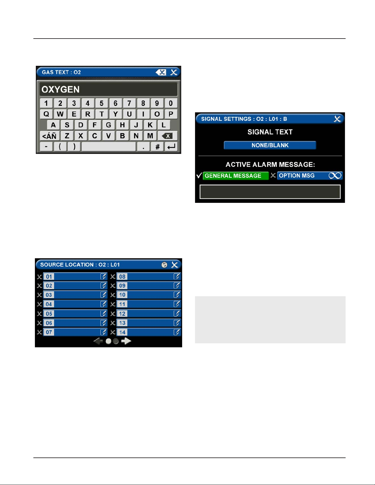
TotalAlert Innity™ HTM Medical Gas Notication System
C = Gas Text Tab
Figure 86: Gas Text Keyboard
To change the name of the gas:
1. Touch the C = [GAS TEXT] tab (Figure 4.85).
2. Touch the Erase button on the keyboard to delete
the gas name.
3. Enter the new gas name. Touch the [<ÁÑ] to toggle
to symbols. Touch the [1AZ] key to toggle back to
letters and numbers.
4. Touch the Save button.
D = Area Monitored
Touch the D = (Area Monitored) Tab
Each Plant (Source) badge has room for 5 signal inputs
(E-J) (Figure 4.85). The rst tab E is used to show the
alarm in “Normal” condition. The (F-H) inputs are used
for warning inputs such as “Change Cylinders” and ash
yellow when active. The last input (J) is used for the
fault condition and ashes red when in fault mode.
To select source signal input text:
Figure 88: Signal Settings Screen
1. Scroll through the options using the right and left
arrows at the bottom of the screen.
2. Touch the tab for the appropriate option, or select
a blank to create a custom alarm.
3. Touch the Save button when you see a check
beside your selection to close and return to the
SIGNAL SETTINGS screen.
4. Touch the X button in the upper right to close and
return to the CONFIGURE (SOURCE) screen.
Figure 87: Congure Channels
On the SOURCE LOCATION screen:
1. Touch the 01 tab. 1.
2. Using the keyboard, enter the name of the location
for the source equipment being monitored (e.g.,
ROOM 1). Enter multiple locations as needed (e.g.,
Manifold Room, Roof Top, Source Room).
3. Touch the Save button. A check appears when the
location is saved. Note: To edit the location, touch
the Pencil button.
4. Touch the X button to close and return to the
CONFIGURE (SOURCE) screen.
Active Alarm Instruction:
To set facility instructions for active alarms, touch
either the GENERAL MESSAGE or OPTION MSG
tab. The alarm defaults to GENERAL MESSAGE. See
Section 4.6 for how to set up custom instructions.
4-25
4107 9016 60.01
Page 60
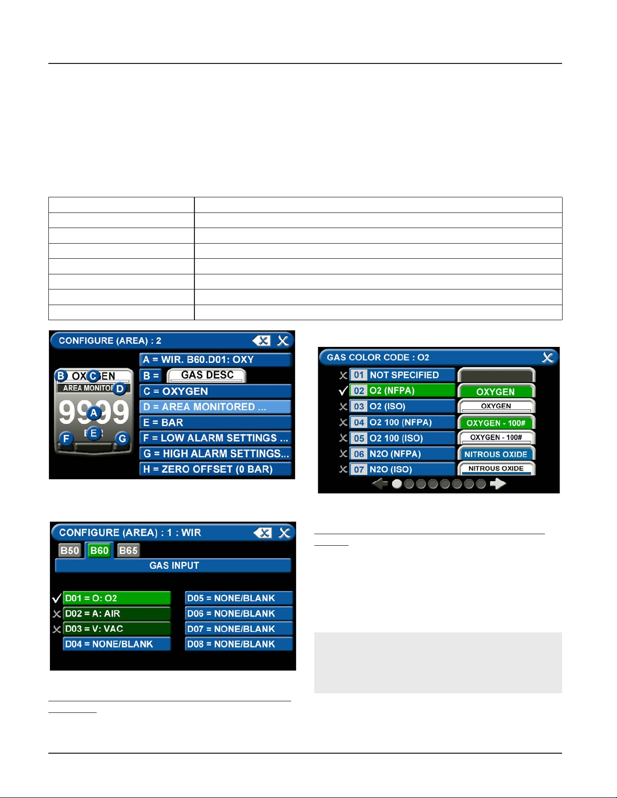
TotalAlert Innity™ HTM Medical Gas Notication System
4.5.2 Conguring Gas ID Badges
The TotalAlert Innity™ Area alarm is designed to allow
conguration of eight gas badges using the B60 board.
To congure the rst badge to custom settings, touch
the [1] button in the numeric display of the conguration screen (Figure 4.83).
Eight tabs are used for conguration (Figure 4.89). Tabs
are listed in alphabetical order.
A = [GAS INPUT] To change which wired input should be shown on the badge
B = GAS DESC To change color codes based on standard and country
C = [GAS NAME] To label the gas
D = AREA MONITORED To edit the location label for a specic gas
E = [UNITS OF MEASURE] To change the displayed unit of measure for the pressure/vacuum
F = LOW ALARM SETTINGS To adjust the value that indicates that the pressure is low
G = HIGH ALARM SETTINGS To adjust the value that indicates that the pressure is high
H = ZERO OFFSET To make small adjustments to the displayed pressure based on user preference
B = Gas Desc Tab
Figure 89: Conguring Gas Badges
A = [Gas Input] Tab
Figure 90: [Gas Input] Tab
To change which wired sensor should be displayed on
that badge:
1. Touch the tab for the appropriate wired gas sensor.
2. Touch the Save button to close the screen.
4107 9016 60.01
Figure 91: Gas Color Code Screen
To change color codes based on your standard and
country:
1. Scroll through the codes using the right and left
arrows at the bottom of the screen.
2. Touch the tab for the appropriate code.
3. Touch the Save button when you see a check
beside your selection.
NOTE:
If the alarm default is correct, touch the X button
in the upper right to close the screen.
4-26
Page 61
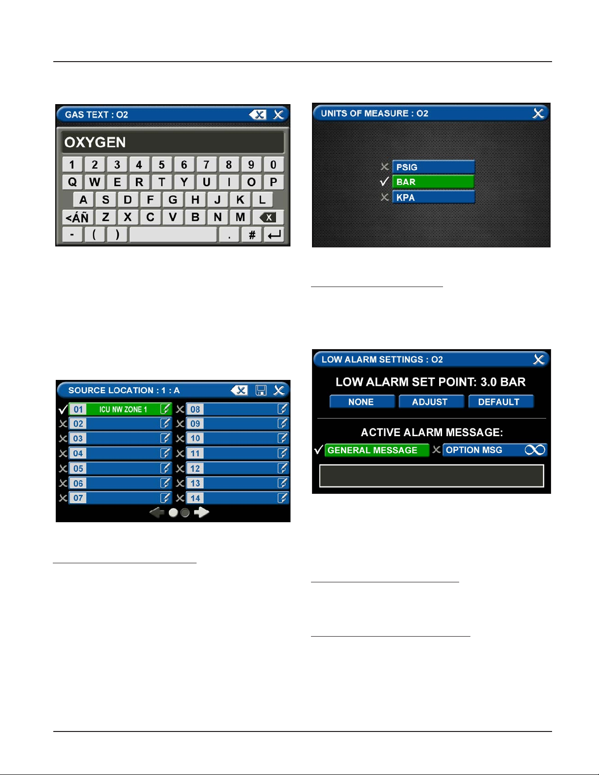
TotalAlert Innity™ HTM Medical Gas Notication System
C = [Gas Name] Tab
Figure 92: Gas Text Screen
1. Touch the Erase button on the keyboard to delete
the gas name.
2. Enter the new gas name. Touch the [<ÁÑ] to toggle
to symbols. Touch the [1AZ] key to toggle back to
letters and numbers.
3. Touch the Save button.
D = Area Monitored Tab
E = [Units Of Measure] Tab
Figure 94: [Units of Measure] Tab
To change the unit of measure:
1. Touch the tab for the appropriate unit of measure.
2. Touch the Save button to close the screen
F = Low Alarm Settings Tab
Figure 93: Area Monitored
To add locations to be monitored:
1. Touch an unused location tab.
2. Using the keyboard, enter the name of the location
that you would like to monitor (e.g., ROOM 1). Enter
multiple locations as needed (e.g., Room 1, Room 2,
Room 5).
3. Touch the Save button. A check appears when the
location is saved.
Note: To edit the location information, touch the Pencil
button.
Figure 95: Low Alarm Settings Tab
• Low Alarm Set Point
You can remove the low alarm set point or customize
the low alarm set point.
To remove the low alarm set point:
1. Touch the NONE tab.
2. Touch the check on the CONFIRM SETTINGS
CHANGE screen.
To customize the low alarm set point:
1. Touch the ADJUST tab.
2. Enter the new set point.
3. Touch the Save button.
4-27
4107 9016 60.01
Page 62
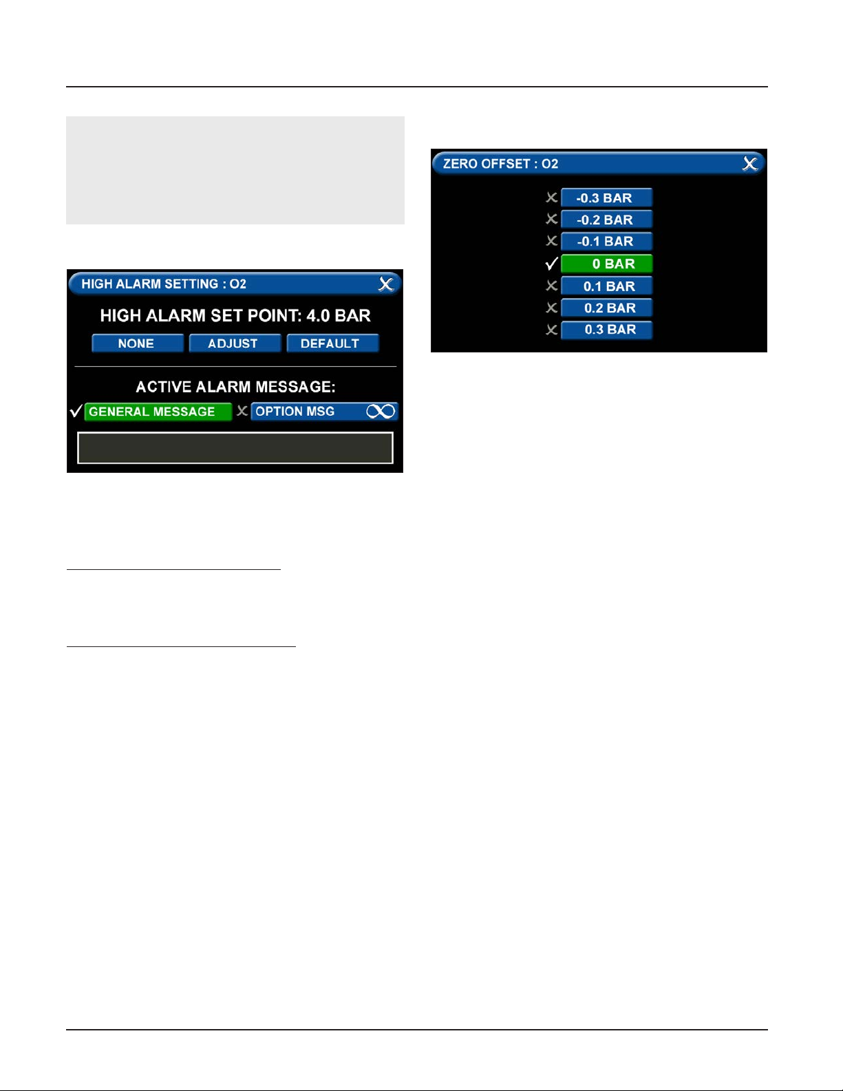
TotalAlert Innity™ HTM Medical Gas Notication System
Active Alarm Instruction:
To set facility instructions for active alarms, touch
either the GENERAL MESSAGE or OPTION MSG tab.
The alarm defaults to GENERAL MESSAGE. See Section 4.6 for how to set up custom instructions.
G = High Alarm Settings Tab
Figure 96: High Alarm Settings Tab
You can remove the high alarm set point or customize
the high alarm set point.
To remove the high alarm set point:
1. Touch the NONE tab.
2. Touch the check on the CONFIRM SETTINGS
CHANGE screen.
To customize the high alarm set point:
1. Touch the ADJUST tab.
2. Enter the new set point.
3. Touch the Save button.
H = Zero Oset Tab
Figure 97: Zero Oset Tab
In some cases, facility dial gauges may show slightly
dierent readings than the TotalAlert alarm (e.g., 3.1
BAR versus 3.0 BAR). To match the TotalAlert alarm
exactly to a facility dial gauge:
1. Select the oset amount.
2. Touch the Save button to close the screen.
Conguring Additional Area Badges
Congure additional area badges by touching the
number on the numeric display that corresponds with
the area badge and repeating the steps listed above.
4107 9016 60.01
4-28
Page 63
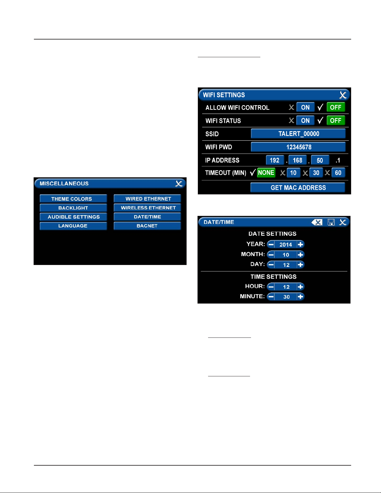
TotalAlert Innity™ HTM Medical Gas Notication System
4.5.4 Miscellaneous Tab
Users can customize certain aspects of the TotalAlert
Innity™ Alarm’s appearance and functionality. One
aspect of changing the Alarms appearance is that the
users can select between English, Spanish, and French
by touching the “LANGUAGE” tab and choosing the
coorisponding language. See section 9.0 for all other
non-latin languages to be setup.
Also, to preserve the life of the LED display, the TotalAlert Innity™ Alarm allows for the user to adjust the
time that the display backlight will remain on with no
motion detected
.
• Touch the BACKLIGHT tab.
• Then select 5 to 60 minutes, or Never tab.
• Save setting by pressing the Save icon.
The WIFI screen shows:
• WIFI status
• SSID
• IP address
Figure 99: WIFI Settings Screen
Figure 98: Miscellaneous Screen
Two other functions that can be adjusted are the WIFI
settings and the date and time settings.
• Touch the MISCELLANEOUS tab.
• Wireless Ethernet Settings Tab
The WIRELESS ETHERNET SETTINGS screen allows for
customization of the WIFI settings. All of the tabs on
this screen are set to default status.
• Touch the WIRELESS ETHERNET tab.
• To turn the WIFI on, touch the WIFI STATUS / ON
tab.
• To change the WIFI password—STRONGLY
RECOMMENDED—touch the WIFI PWD tab.
Using the keyboard, enter a new password.
Touch the Save button to close and return to the
WIFI SETTINGS screen.
• To add the WIFI settings to the INFORMATION
screen, touch the ALLOW WIFI CONTROL / ON tab.
Touch the Save button.
• The INFORMATION screen will now display a WIFI
tab.
Figure 100: Date/Time Settings Screen
• Date/Time Settings Tab
For DATE SETTINGS, use the plus and minus signs to
adjust the:
• Year
• Month
• Day
For TIME SETTINGS, use the plus and minus signs to
adjust the 24-hour clock:
• Hour
• Minute
4-29
4107 9016 60.01
Page 64
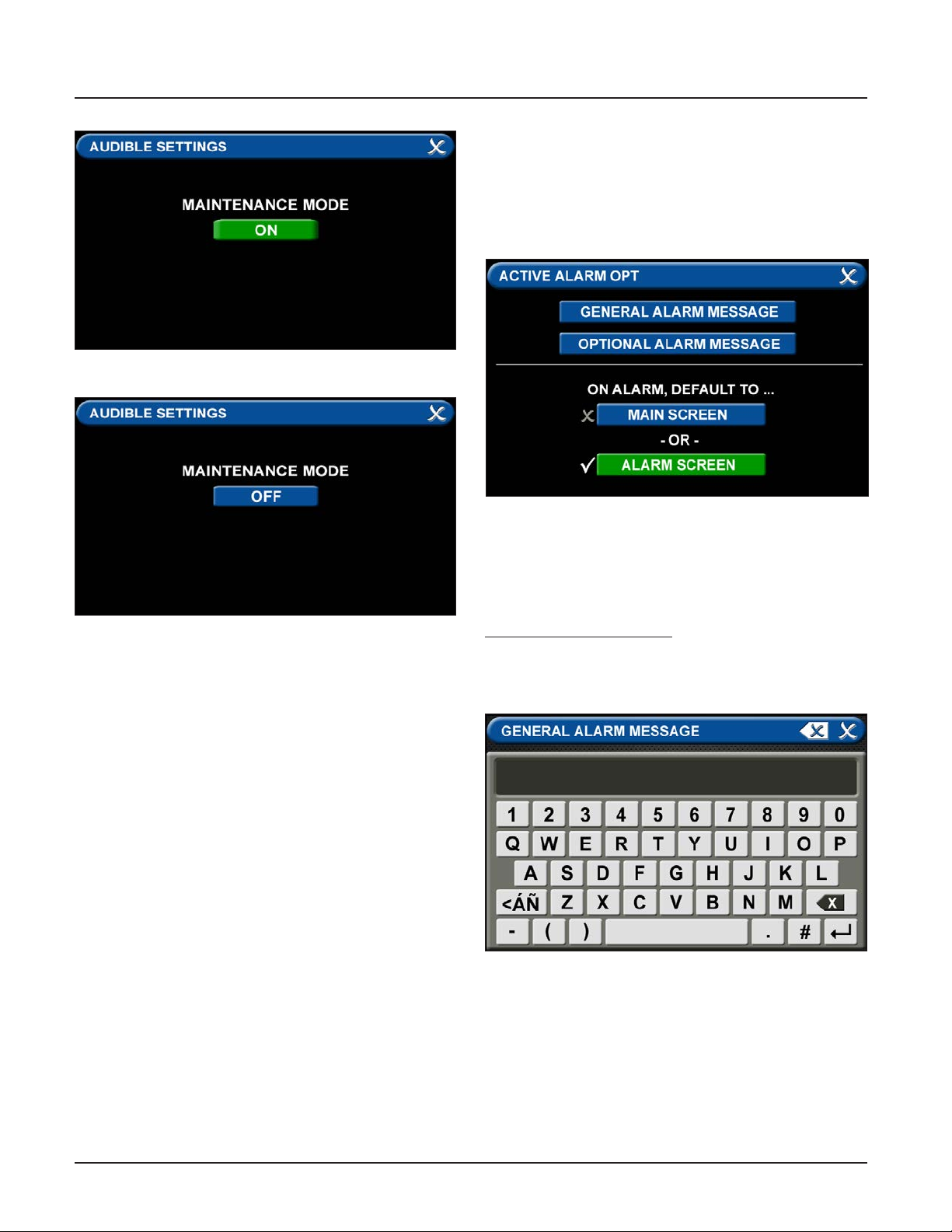
TotalAlert Innity™ HTM Medical Gas Notication System
4.6 Customized Instructions Set Up
Active Alarm Opt Tab
The ACTIVE ALARM OPT tab allows users to customize
their Active Alarm options in two ways: by adding alarm
instructions and by changing the alarm default screen.
Figure 101: Maintenance Mode ON
Figure 103: Active Alarm Opt Tab
Figure 102: Maintenance Mode OFF
• Audible Settings Tab
The AUDIBLE SETTINGS tab allows for the alarm to
be put in Maintenance Mode. When the Maintenance
mode tab is toggled “ON”, the audible warning will not
reinitialize.
Maintenance mode will automatically change to OFF if
a new alarm condition is introduced or all alarm
conditions are cleared.
• Adding Custom Alarm Instructions
Users can add instructions—both general instructions
and specic instructions—to facility personnel for when
the alarm goes into fault status.
To add general instructions:
• Touch the GENERAL ALARM MESSAGE tab
• Enter the instruction.
Figure 104: General Alarm Message Tab
4107 9016 60.01
4-30
Page 65
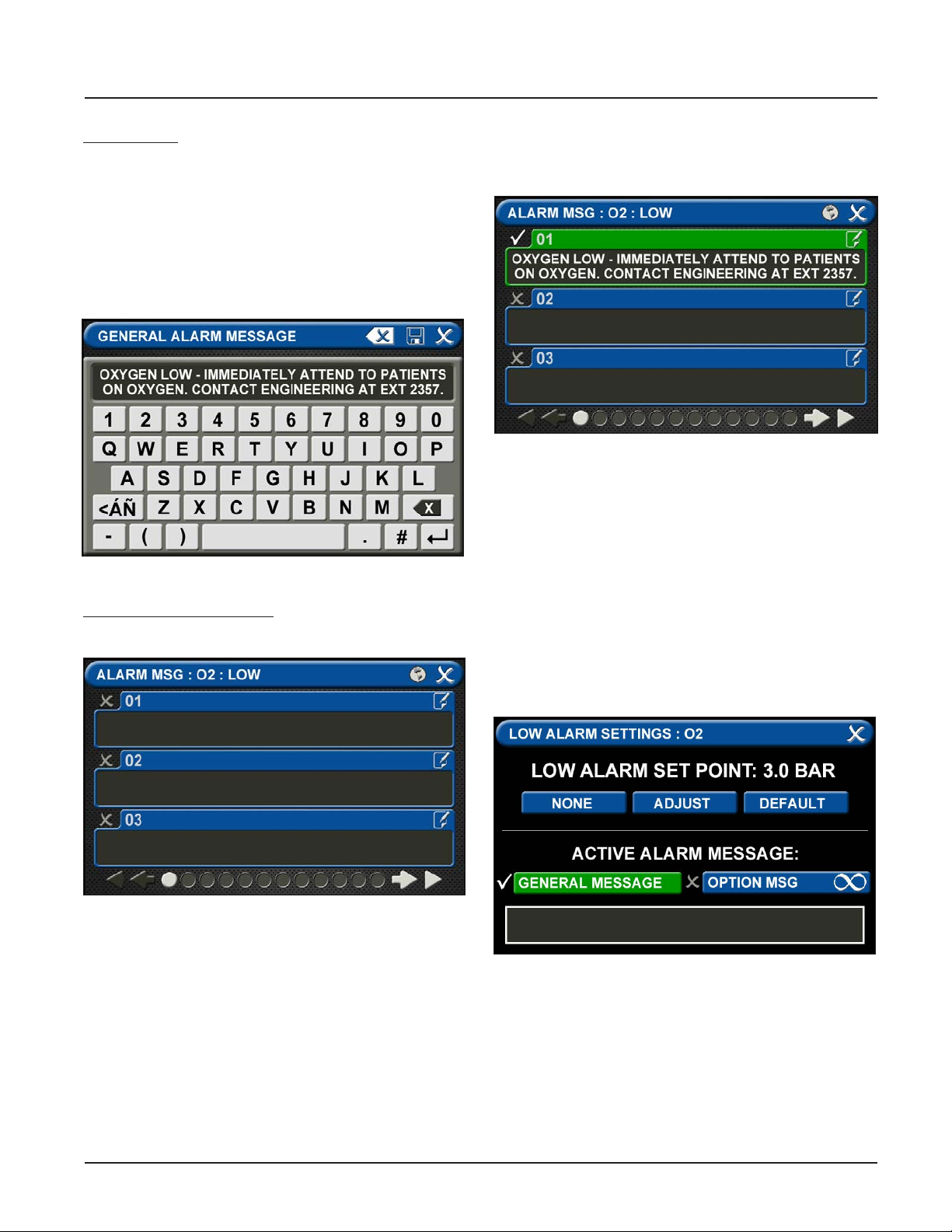
TotalAlert Innity™ HTM Medical Gas Notication System
Keyboard tips:
• Touch the [<ÁÑ] to toggle to symbols. Touch the
[1AZ] key to toggle back to letters and numbers.
• As text is entered, the letters will decrease in
size. This feature helps to accommodate a longer
message.
• To add a second line of text, use the Enter button.
• Touch the Save button to close and return to the
ACTIVE ALARM OPT screen
Figure 105: General Alarm Message Screen
To add specic instructions:
• Touch the OPTIONAL ALARM MESSAGE tab.
• Touch the 01 tab. Enter the instruction. Touch the
[<ÁÑ] to toggle to symbols. Touch the [1AZ] key to
toggle back to letters and numbers.
Figure 107: Optional Alarm Message
• Touch the Save button to close.
• Repeat to add additional instructions.
• Touch the X button to close and return to the
ALARM MESSAGES screen.
• Touch the X button to close and return to the
ACTIVE ALARM OPT screen.
• To tie an optional alarm message, or specic
instruction, to a set point, go to the LOW ALARM
SETTINGS screen or the HIGH ALARM SETTINGS
screen for that gas.
• Touch the OPTION MSG tab.
Figure 106: Alarm Messages Screen
4-31
Figure 108: Low Alarm Settings
4107 9016 60.01
Page 66
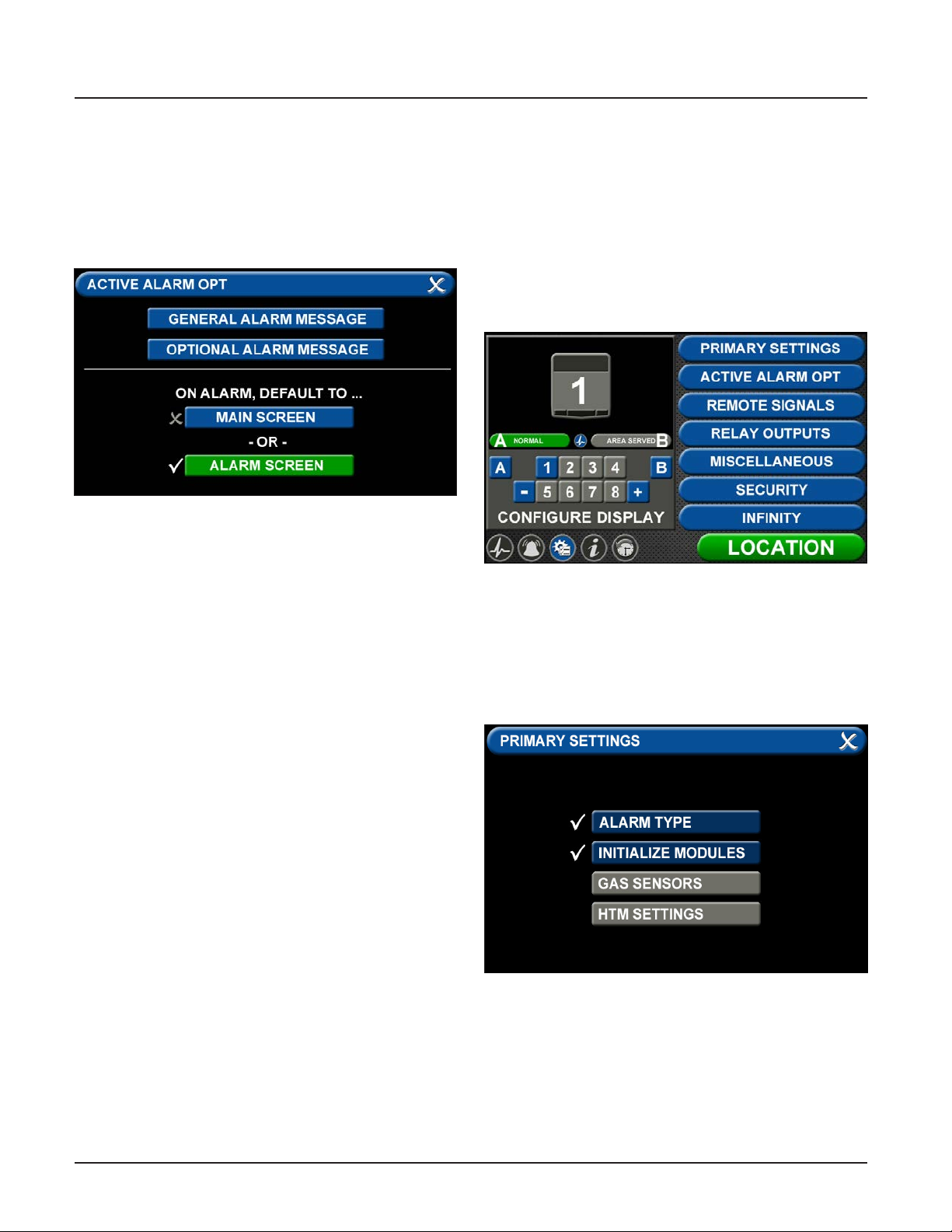
TotalAlert Innity™ HTM Medical Gas Notication System
• Touch the X button to the left of the appropriate
instruction tab. When your selection appears
checked and highlighted, touch the Save button.
• This specic instruction (rather than the general
instructions) will now display on the ACTIVE ALARM
screen when the alarm is in fault status. It will also
display on the ALARM POINTS screen.
Figure 109: Alarm Message: High
• Changing the Alarm Default Screen
• The TotalAlert Innity™ Area Alarm switches to the
ACTIVE ALARM screen if the alarm goes into fault
status.
• To congure the alarm so that the MAIN screen
appears in the event of a fault, touch the MAIN
screen tab.
• If the alarm is already displaying the MAIN screen
when it goes into fault status, the toolbar will
switch from Normal to Icon and the high or low
pressure indicator on the gas badge will ash for
the gas pressure out of range.
4.7 Additional Components
4.7.1 4-20 mA Devices
To congure a 4-20mA device for monitoring, start
on the CONFIGURATION screen. Users are always
prompted to enter the password when accessing this
screen. Type the password, and touch the Enter button.
The CONFIGURATION screen displays.
Figure 110: Conguration screen
The TotalAlert Innity™ alarm is designed to allow
conguration of four gas badges using the B50 board
to monitor 4-20mA devices. The alarm must be set as
an Area panel or Combination panel. See Alarm Type
Tab in Section 4.3.2.
4107 9016 60.01
Figure 111: Primary Settings screen
4-32
Page 67
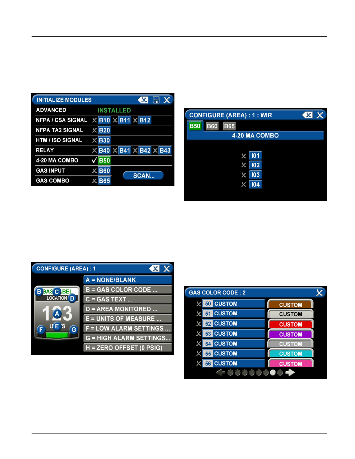
TotalAlert Innity™ HTM Medical Gas Notication System
After conguring the Alarm Type, the B50 board must
be initialized. Select “Initialize Modules” on the Primary
Settings Screen. Press the “Scan” button to make sure
the B50 board is set up, as it should turn green. Once
the B50 board is green, press the “Save” icon to exit the
screen. Exit the “Primary Settings” screen.
Figure 112: initialize Modules screen
To congure the rst badge to custom settings, touch
the corresponding number button in the numeric
display that represents the badge to be congured. If
a badge needs to be added, press the “+” for additional
badges.
Eight tabs are used for conguration of a custom
badge. Tabs are listed in alphabetical order.
A = [Gas Input] Tab
The B50 should be green and there should be 4
choices (I01, I02, I03, I04). Select the wired input to be
displayed on that badge.
Touch the tab for the appropriate wired gas sensor.
Touch the Save button to close the screen.
Figure 114: B50 Tab, 4-20 mA
B = Gas Desc Tab
To assign a color code for the device:
1. Scroll through the codes using the right and left
arrows at the bottom of the screen. Custom colors
are located on pages 7-8.
2. Touch the tab for the appropriate code.
3. Touch the Save button when you see a check
beside your selection.
Figure 113: Congure Area screen
4-33
Figure 115: Gas Color Code Tab
4107 9016 60.01
Page 68
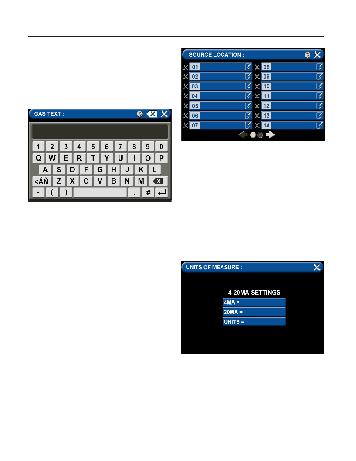
TotalAlert Innity™ HTM Medical Gas Notication System
C = [Gas Name] Tab
Use the keyboard to assign a device name. Type in the
name of the device to be monitored. Touch the [<ÁÑ]
to toggle to symbols and extended Latin Characters.
Touch the [1AZ] key to toggle back to letters and
numbers.
Touch the Save button when complete.
Figure 117: Source Location
E = [Units of Measure] Tab
To set up the 4-20mA device:
1. Touch the tab for “4MA=” to set the low
measurement point of the device (zero for
example) and press the save button to exit.
2. Touch the tab for “20MA=” to set the high
Figure 116: Gas Text Keyboard
D = Area Monitored Tab
To add locations to be monitored:
1. Touch an unused location tab.
2. Using the keyboard, enter the name of the
location that you would like to monitor (e.g., ROOM
1). Enter multiple locations as needed (e.g., Room
1, Room 2, Room 5).
3. A check appears when the location is selected, the
save button has to be pressed if the selection is
new.
To edit the location information, touch the Pencil
button.
measurement point of the device (100 for example)
and press the save button to exit.
3. Touch the tab for “Units=” to set the method of
measurement (percent for example), type in the
measurement type and press the save button to
exit.
4. Touch the X button in the upper right to close the
screen.
4107 9016 60.01
Figure 118: Units of Measure Tab
4-34
Page 69
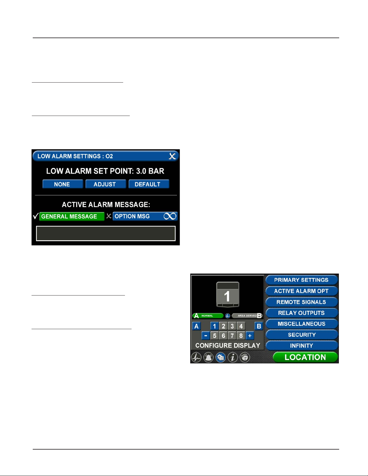
TotalAlert Innity™ HTM Medical Gas Notication System
F = Low Alarm Settings Tab
You can remove the low alarm set point or customize
the low alarm set point.
To remove the low alarm set point:
1. Touch the NONE tab.
2. Touch the check on the CONFIRM SETTINGS
CHANGE screen.
To customize the low alarm set point:
1. Touch the ADJUST tab.
2. Enter the new set point.
3. Touch the Save button.
Figure 119: Low Alarm Settings
G = High Alarm Settings Tab
You can remove the high alarm set point or customize
the high alarm set point.
To remove the high alarm set point:
1. Touch the NONE tab.
2. Touch the check on the CONFIRM SETTINGS
CHANGE screen.
To customize the high alarm set point:
1. Touch the ADJUST tab.
2. Enter the new set point.
3. Touch the Save button.
Active Alarm
To setup active alarm General Message:
1. Touch the General Message tab to activate general
message.
2. Touch the gray text box at bottom of screen to type
in general message.
3. Using the keyboard, enter the message that you
would like to be active when in alarm mode and
save.
To setup active alarm Option Message:
1. Touch the Optional Message tab to activate
optional message.
2. Touch the 01 tab.
3. Using the keyboard, enter the optional message
that you would like to be active when in alarm
mode and save.
Conguring Additional 4-20mA Devices
Congure additional 4-20mA devices by touching the
number on the numeric display that corresponds with
the gas badge and repeating the steps listed above.
4.7.2 Relay Output Board (B4X Board)
To congure a Relay Output, start on the CONFIGURATION screen. Users are always prompted to enter the
password when accessing this screen.
Type the password, and touch the Enter button.
The CONFIGURATION screen displays.
4-35
Figure 120: Conguration Screen
4107 9016 60.01
Page 70
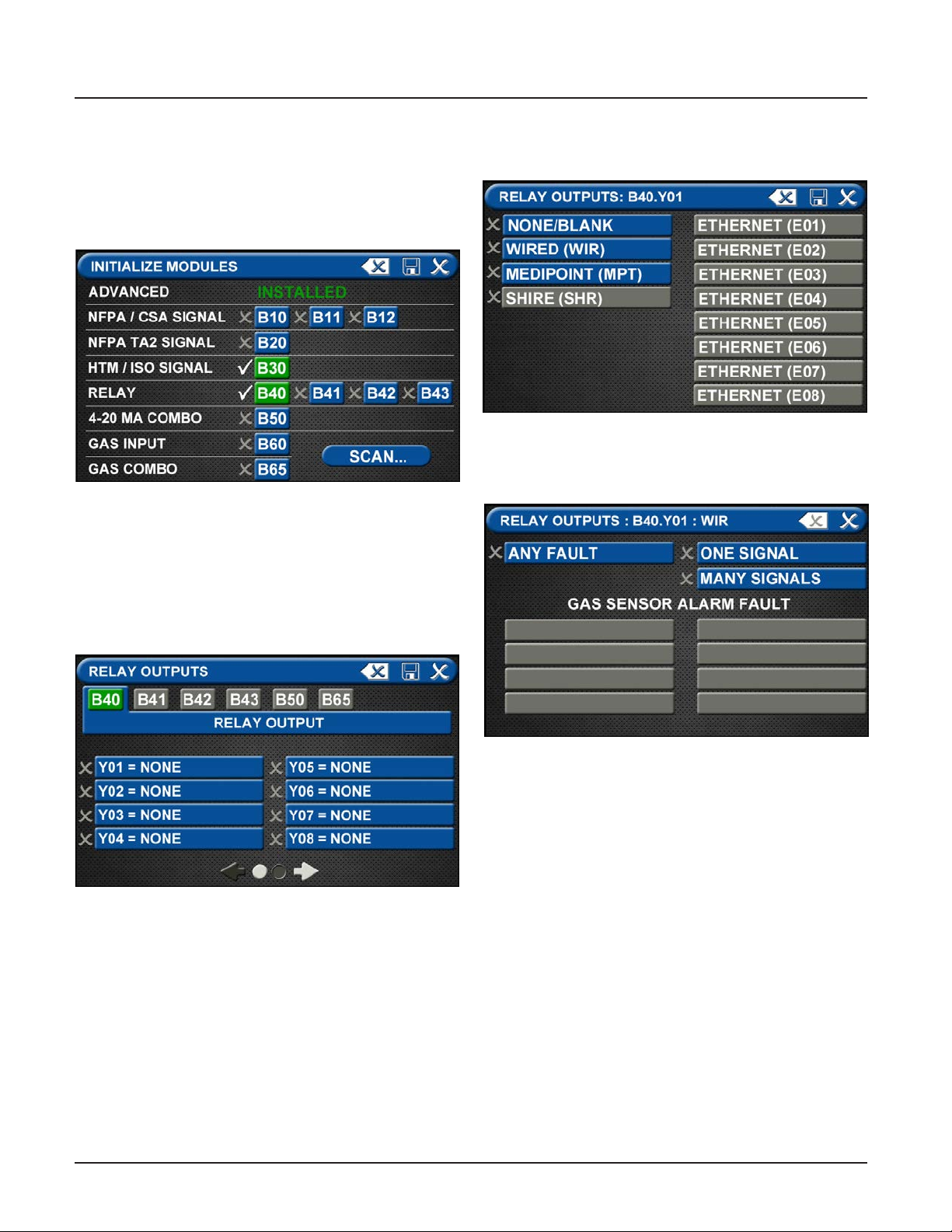
TotalAlert Innity™ HTM Medical Gas Notication System
The B40 (or B41) board must be initialized. Touch
Primary Settings from the right side menu, then select
“Initialize Modules”. Press the “Scan” button to make
sure the B40 board is set up, as it should turn green.
Once the B40 board is green, press the “Save” icon to
exit the screen. Exit the “Primary Settings” screen.
Figure 121: Initialize Modules Screen
The next step is to select the “Relay Outputs” from the
menu on the Conguration Screen. The B40 board
should be highlighted in Green (or other Relay Output
board installed in the backbox).
Select the signal that corresponds to the output wires
on the relay board (Y01 for example).
Select the corresponding “Ethernet” if an Ethernet
signal has been set up. (See Mirroring in Section 4.6.4.)
Figure 123: Relay Output Signal
There are three choices for the relay output signal.
Figure 122: Relay Outputs Screen
After selecting the signal, you will need to assign it to
an alarm signal to send. Select “Wired” on the Relay
Output screen if the signal to be relayed is wired into
the backbox.
4107 9016 60.01
Figure 124: Relay Output Signals Screen
1. A single “Any Fault” which will report a general
alarm fault if any of the alarm signals on the alarm
go into alarm condition. To select “Any Fault”, press
the blue “Any Fault” to change it to green with the
check mark. Then press Save to return to Relay
Outputs and set up additional outputs.
2. “One Signal” reports a single signal through the
relay output. When pressing “One Signal”, the next
step is to assign the signal to be transmitted.
On the Relay Output screen, select the Input Signal
to be transmitted (C1X1 from the B30 board for
example). Press Save to return to the Relay Outputs screen.
4-36
Page 71
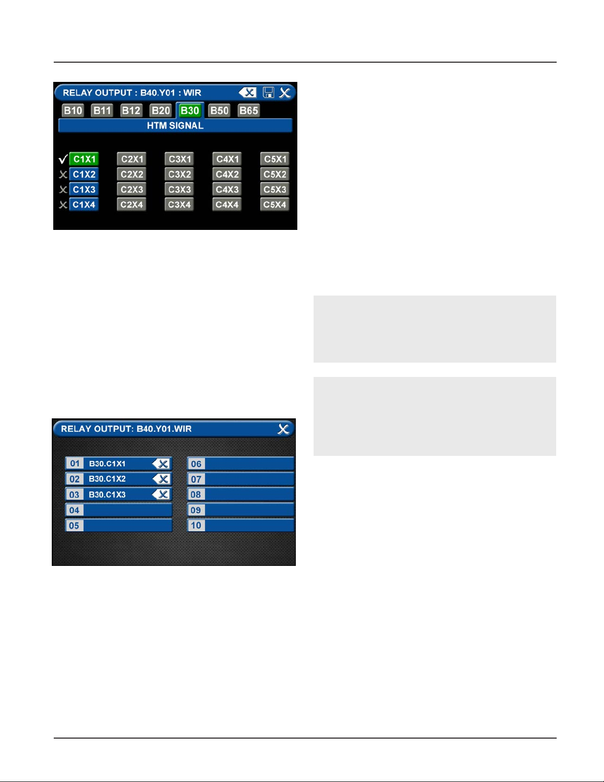
TotalAlert Innity™ HTM Medical Gas Notication System
4.7.3 Wired Ethernet Setup
The TotaAlert Innity™ Notication System allows for
networking via standard Ethernet. Any alarm panel can
be remotely observed on the network using a standard
web browser.
IP Address using DHCP method: Upon power-up of
the system, the device will search for a DHCP server. If
a DHCP server is found, IP Address, subnet mask and
gateway are automatically obtained. If not found, the
device will check for a DHCP server every 30
seconds. When found, the IP Address, subnet mask and
Figure 125: Relay Output One Signal
3. “Many Signals” allows the user to group multiple
signals on a single relay output. If any of the signals
goes into alarm condition, the relay output will
report an alarm condition. Press “Many Signals”
to move to the Relay Output screen and select
from 1 to 10 signals to group together. Select the
number 01 to start, then select the rst signal to
be grouped by pressing the corresponding number
on the Relay Output (such as C1X1 from the B30
board). Press Save to return to the Many Signal
Relay Output screen. Next select 02 to capture
the second signal to be monitored. Repeat up to a
grouping of 10 signals.
gateway are automatically obtained.
IP Address using Static method: Upon power up of the
system, the device will immediately
begin using the xed IP conguration.
CAUTION:
Only facility information systems personnel should
set up the network interface. If the set up is done
improperly, equipment may not perform properly.
CAUTION:
The information systems personnel should be no-
tied before changing any of the network settings.
Changing the settings could keep the equipment
from working properly.
Figure 126: Relay Output Many Signals
4-37
4107 9016 60.01
Page 72
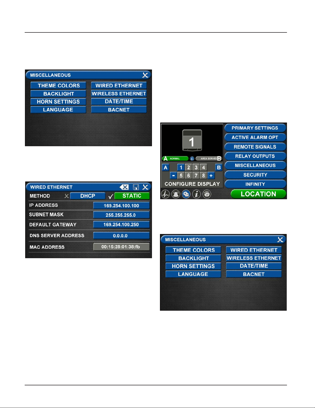
TotalAlert Innity™ HTM Medical Gas Notication System
Wired Ethernet Settings
On the Miscellaneous screen, touch the WIRED
ETHERNET tab (Figure 4.113).
Figure 127: Miscellaneous Screen
The WIRED ETHERNET screen allows for
customization of the Ethernet settings. All of the tabs
on this screen are set to default status.
4.7.4 BACnet Set-Up
The TotalAlert Innity™ alarms employ the TCP/IP
family of protocols for communication and each device
has a unique IP address. The alarm utilizes a built-in
Ethernet connection for BACnet transmission of signals
to a Building Automation System. The TotalAlert
Innity™ alarm panel conforms to the BACnet protocol
and includes a Protocol Implementation Conformance
Statement (PICS).
• Touch the MISCELLANEOUS tab located on the
conguration screen.
Figure 128: Wired Ethernet Screen
• The alarm IP Address defaults to Static method. To
select the DHCP method, touch the DHCP tab.
• To change the IP Address, touch the IP Address tab.
Using the keyboard, enter a new IP address.
• To change the Subnet Mask, touch the Subnet
Mask tab. Using the keyboard, enter a new Subnet
Mask address.
• To change the Default Gateway, touch the Default
Gateway tab. Using the keyboard, enter a new
Default Gateway.
• To change the DSN Server Address, touch the DSN
Server Address tab. Using the keyboard, enter a
new DSN Server Address.
Figure 129: Conguration Screen
• Touch the BACNET tab to access the BACNET
control screen.
Figure 130: Miscellaneous Screen
• To allow BACnet communication, touch the BACnet
ON tab.
• To add the name, touch the DEVICE NAME tab and
enter the name through the on screen keyboard.
4107 9016 60.01
4-38
Page 73
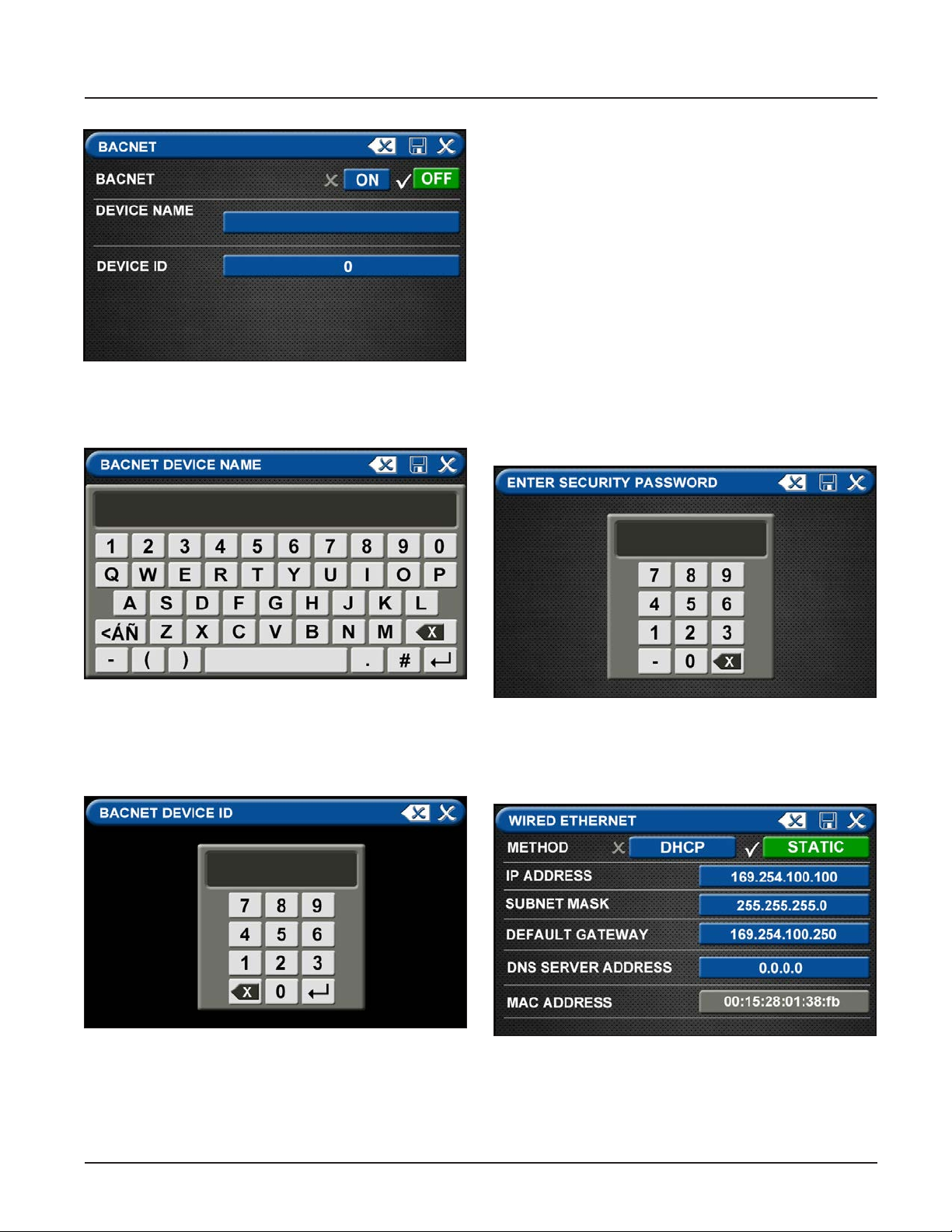
TotalAlert Innity™ HTM Medical Gas Notication System
4.7.5 “Mirroring” Two Alarm Panels
Each alarm panel has an Ethernet port on the back of
the front panel assembly. By connecting the alarm to
the hospital network, via Ethernet, or directly cabling it
to another alarm panel, signals and gas pressures can
be pulled from one panel and displayed on another
panel
An category 5 CROSS OVER cable is required for connecting alarm panels directly to each other. Otherwise,
standard cabling can be used with a facility’s Ethernet
Figure 131: BACnet Screen
• Save the BACnet device name by touching the save
button located in the top right corner of the screen.
hub or switch to connect panels.
Setup of alarm to be “mirrored”
Start on the Conguration screen.
• Enter Security Password
Figure 132: BACnet Device Name
• To add the ID, touch the DEVICE ID tab and enter
the ID number provided by the Building
Management System administrator.
Figure 133: BACnet Device ID
• Save settings.
• Touch the X in the top right corner to exit out of the
BACnet setup screen.
Figure 134: Security Password
• Touch the MISCELLANEOUS tab located on the
setup screen
Figure 135: Wired Ethernet Control Screen
4-39
4107 9016 60.01
Page 74
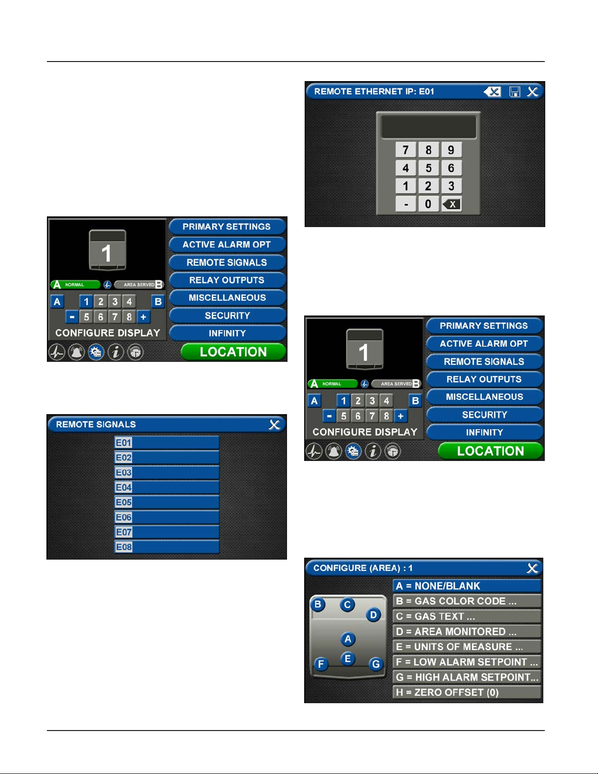
TotalAlert Innity™ HTM Medical Gas Notication System
• Touch Wired Ethernet tab to access the Wired
Ethernet control screen (Section 4.7.3).
• Conguration of the Wired Ethernet settings to be
performed by facility’s IT specialist. Settings for the
IP Address, Subnet Mask, Default Gateway, and
DNS Server Address to conform to facility’s network.
• Touch the Save button to close and return to the
MISCELLANEOUS Screen.
• Exit the MISCELLANEOUS screen and return to the
Conguration screen.
Figure 138: Remote Ethernet IP Address
On the alarm panel that will display the
mirrored signal or pressure:
Gas Badge
• Go to Conguration screen
Figure 136: Conguration Screen
• Touch the REMOTE SIGNALS tab.
Figure 137: Remote Signals Screen
Each alarm panel can mirror signals and pressures
from up to 8 remote alarm panels.
• Touch the E01 tab.
• Enter the Remote Ethernet IP address of the alarm
panel to be mirrored.
• Touch the save button.
Figure 139: Conguration Screen
• Add new badge to be mirrored by touching the [+]
key.
• Touch the badge number to be congured.
• On the CONFIGURE (AREA) screen, touch A=None/
Blank tab to set up badge.
4107 9016 60.01
Figure 140: Congure Area Screen
4-40
Page 75
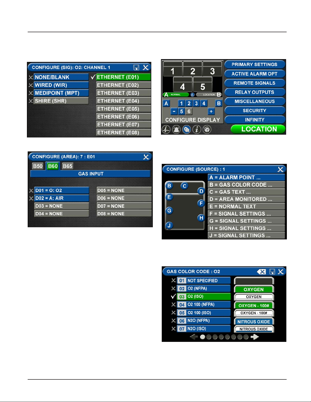
TotalAlert Innity™ HTM Medical Gas Notication System
• Touch the ETHERNET tab that corresponds to
the alarm panel providing the gas pressure to be
mirrored.
Figure 141: Ethernet Screen
Central Signals
• Go to the Conguration screen
Figure 143: Conguration Screen
A = [Gas Color Code] Tab
• Choose the source signal badge that represents the
source gas to be mirrored.
Figure 142: Congure Area Screen
• At the CONFIGURE (AREA) screen (B60 Gas Input),
touch the gas to be mirrored.
• Touch the save button.
• Follow the steps for conguring gas badges listed
in Section 4.3.
Figure 145: Congure Source Locations
• Touch the GAS COLOR CODE tab to select the
proper gas color code.
Figure 146: Gas Color Code Screen
• Select the proper gas color code and standard.
• Touch the save button.
4-41
4107 9016 60.01
Page 76
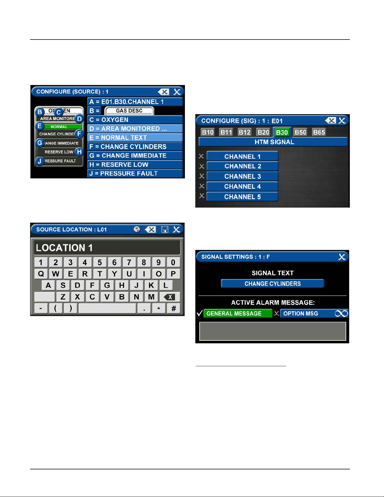
TotalAlert Innity™ HTM Medical Gas Notication System
C = Area Monitored Tab
To add areas to be monitored:
1. Touch the AREA MONITORED tab.
Figure 147: Congure Source Screen
2. Using the keyboard, enter the name of the area
monitored
3. Touch the save button.
D = Normal Text
• Defaults to Normal condition
E = Alarm Point Tab
• Touch the ALARM POINT tab to assign a channel to
the badge.
• Select one of the ve CHANNEL tabs.
• Touch the save button.
Figure 149: Congure Channels
Signal Settings (F-J)
• Choose SIGNAL SETTING Tab F-J
Touch the NONE/BLANK tab.
Figure 148: Location Keyboard
4107 9016 60.01
Figure 150: Signal Settings Screen
To select source signal input text:
• Scroll through the options using the right and left
arrows at the bottom of the screen.
• Touch the tab for the appropriate option, or select
a blank to create a custom alarm.
4-42
Page 77
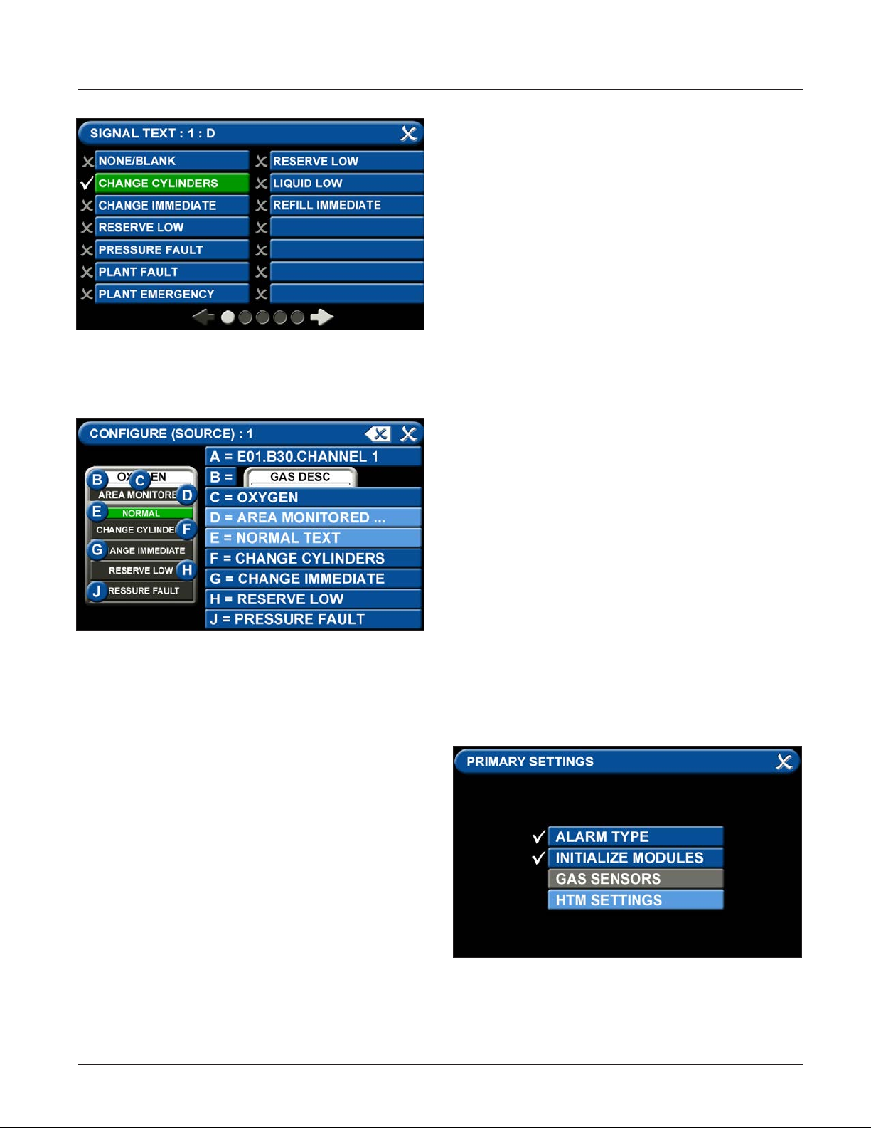
TotalAlert Innity™ HTM Medical Gas Notication System
4.8 Medipoint/Shire Network
4.8.1 Medipoint Network
The Medipoint alarm system works by identifying each
individual gas channel or set or point alarm inputs with
a unique ID. The switches are hexadecimal (i.e. A corresponds to 10, B corresponds to 11 etc. for the purposes
of panel identication. A channel must be set between
0 and F, 0 being OFF.
The panel with the highest ID must be set as the MAS-
Figure 151: Signal Settings Screen
• Touch the Save button when you see a check
beside your selection to save the selection and
return to the SIGNAL SETTINGS screen.
TER panel, all other panels must be set as slave panels.
Therefore an alarm system may contain up to 32 panels with the highest number being set as the MASTER.
An alarm system is set up by allocating a number (1 to
9) or letter (A to F) to each set of plant inputs or point
alarm inputs. Typically on a 4 gas system with point
alarms:
1 - Oxygen Manifold Alarms
2 - Nitrous Oxide Manifold Alarms
3 - Air Plant Alarms
4 - Vacuum Plant Alarms
A - Ward 1 to 4 Point Alarms
B - Ward 5 to 8 Point Alarms
Figure 152: Signal Settings Screen
• To congure the remaining signal settings, repeat
the above steps.
Therefore on every panel where Oxygen is to be displayed the appropriate gas number is set to 1.
4.8.2 Medipoint Network Setup
Go to the PRIMARY SETTINGS tab (from the conguration screen) to setup the HTM SETTINGS for the Medipoint Network. (See Figure 4.153)
Figure 153: Medipoint Network Setup
4-43
•
4107 9016 60.01
Page 78
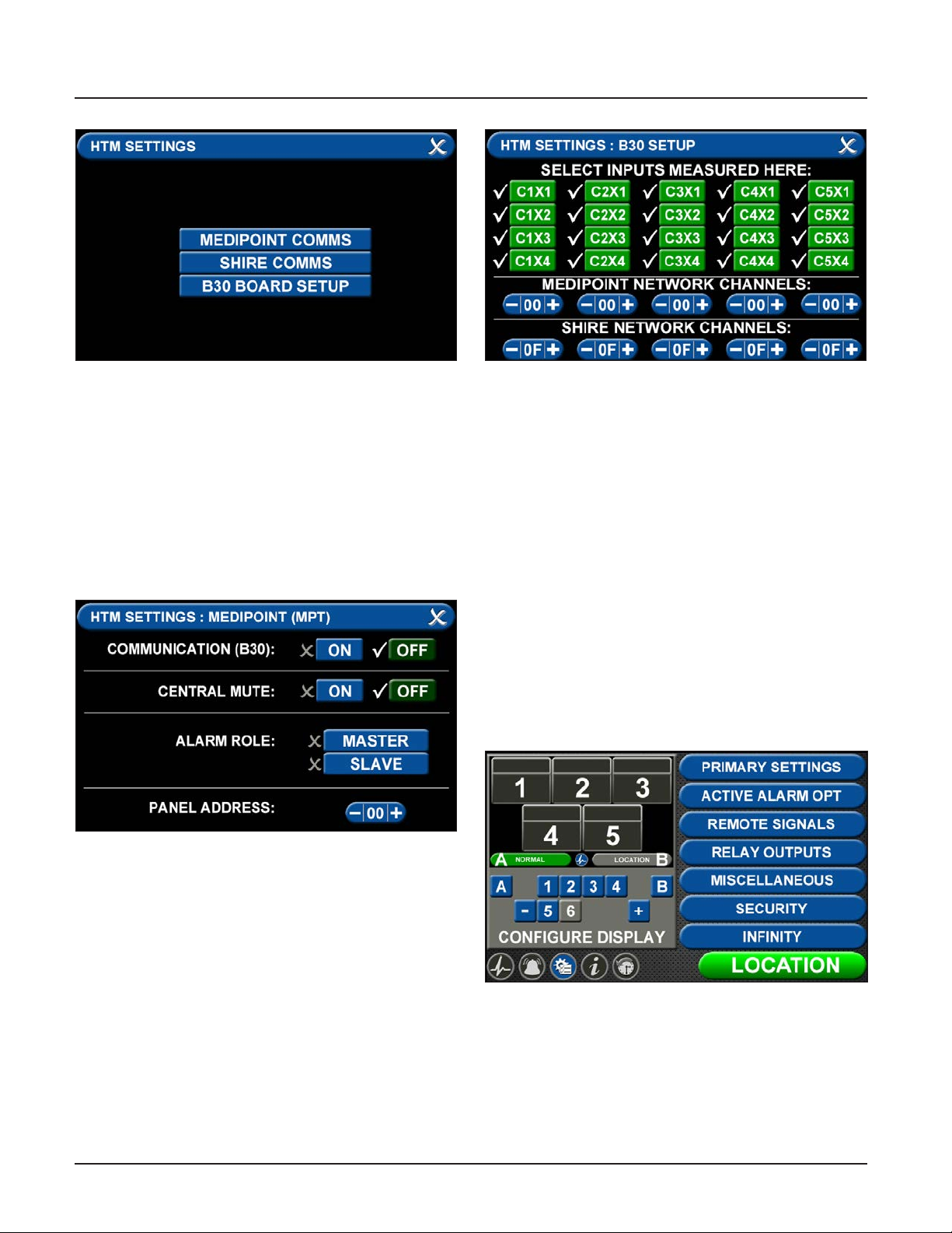
TotalAlert Innity™ HTM Medical Gas Notication System
Figure 154: Medipoint Network Setup
• To communicate with a Medipoint network, press
the MEDIPOINT COMMS tab.
• Communication (B30) can be toggled OFF or ON by
pressing the correlating tabs. Alarm Role between
MASTER and SLAVE can also be selected by pressing the correlating tab.
• Setup the PANEL ADDRESS by pressing the + or tab to the correct setting.
• Press save icon to complete setup.
Figure 156: Medipoint Network Setup
• Select the inputs for signals that will be wired
locally to the alarm.
• Individual tabs can be toggled o and on by adding
or eliminating the check mark by the inputs where
you are landing the wires on the B30 board. Also,
if you are transmitting MEDIPOINT signals, set the
appropriate network channels by pressing the + or
– tab to the correct setting.
• Press save icon to complete setup.
4.8.3 Medipoint Network Gas Badge
Setup
To setup gas badges to communicate on the Medipoint
network:
• Go to conguration screen and select the gas
badge.
Figure 155: Medipoint Network Setup
• To transmit and recieve signals, the HTM Settings
tab has to be initialized (Figure 153).
• Press the B30 BOARD SETUP tab (Figure 154).
4107 9016 60.01
Figure 157: Conguration Screen
• Touch ALARM POINT tab to congure gas badge
4-44
Page 79
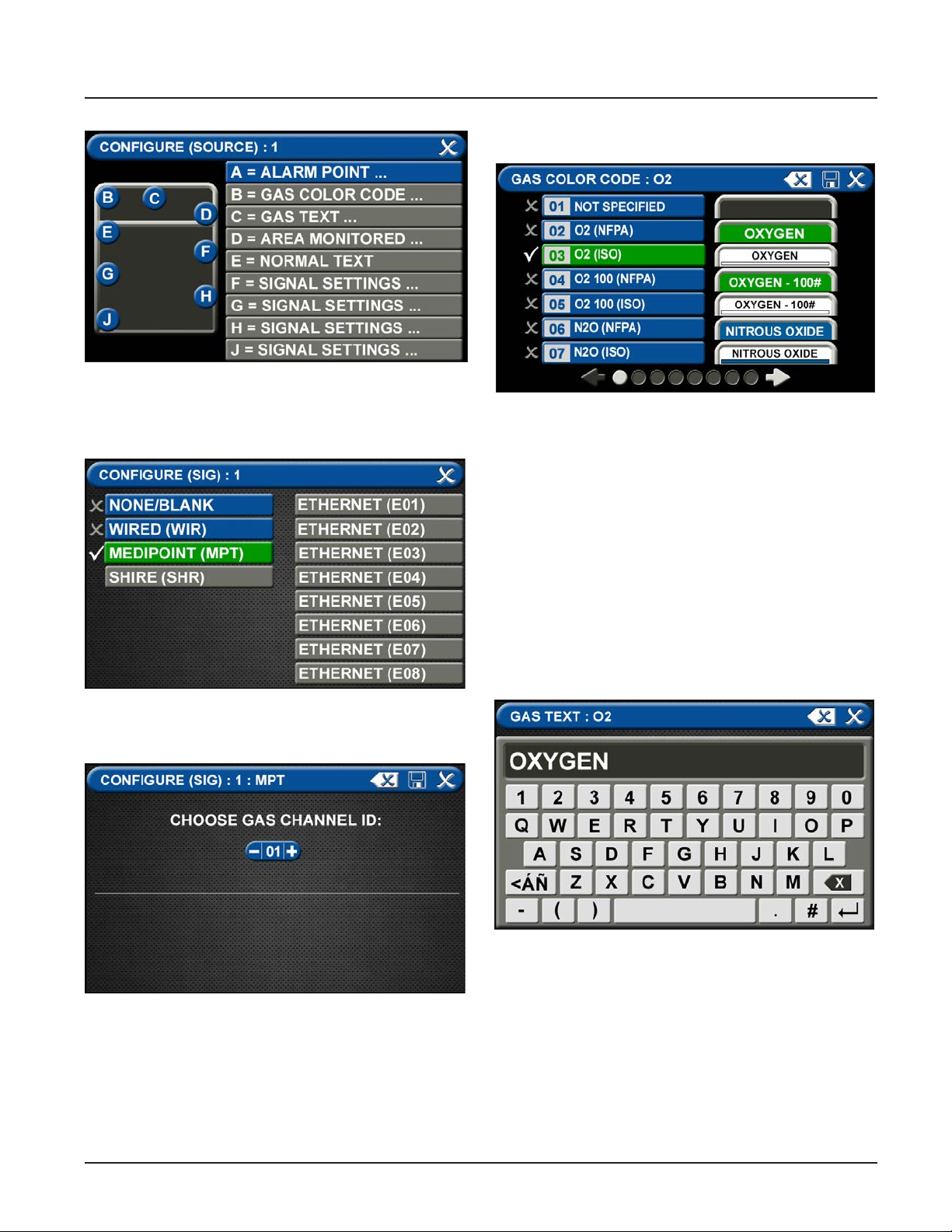
TotalAlert Innity™ HTM Medical Gas Notication System
B = Gas Color Code Tab
Figure 158: Congure Source Locations
A = Alarm Point Tab
• Touch ALARM POINT tab to congure gas badge
Figure 159: Congure Source
• Select MEDIPOINT (MPT) tab
Figure 161: Gas Color Code Tab
To select the color code for the appropriate gas based
on your standard and country:
1. Touch the B = GAS COLOR CODE tab (Figure 4.63)
2. Scroll through the gas types using the right and left
arrows at the bottom of the screen.
3. Touch the tab for the appropriate code, or select a
“custom” tab to create a unique source badge.
4. Touch the Save button when you see a check
beside your selection. This will automatically ll in
tabs C-J with default values for the gas selected. If
changes are needed follow the next steps below.
C = Gas Text Tab
Figure 160: Channel ID
• Use (-) and (+) to select the Gas Channel ID to be
displayed.
• Press Save Icon to complete setup.
Figure 162: Gas Text Keyboard
To add areas to be monitored:
5. Touch the AREA MONITORED tab.
6. Touch on the 01 tab.
Using the keyboard, enter the name of the area. To
change the name of the gas:
1. Touch the C = [GAS TEXT] tab.
2. Touch the Erase button on the keyboard to delete
the gas name.
3. Enter the new gas name. Touch the [<ÁÑ] to toggle
to symbols. Touch the [1AZ] key to toggle back to
4-45
4107 9016 60.01
Page 80
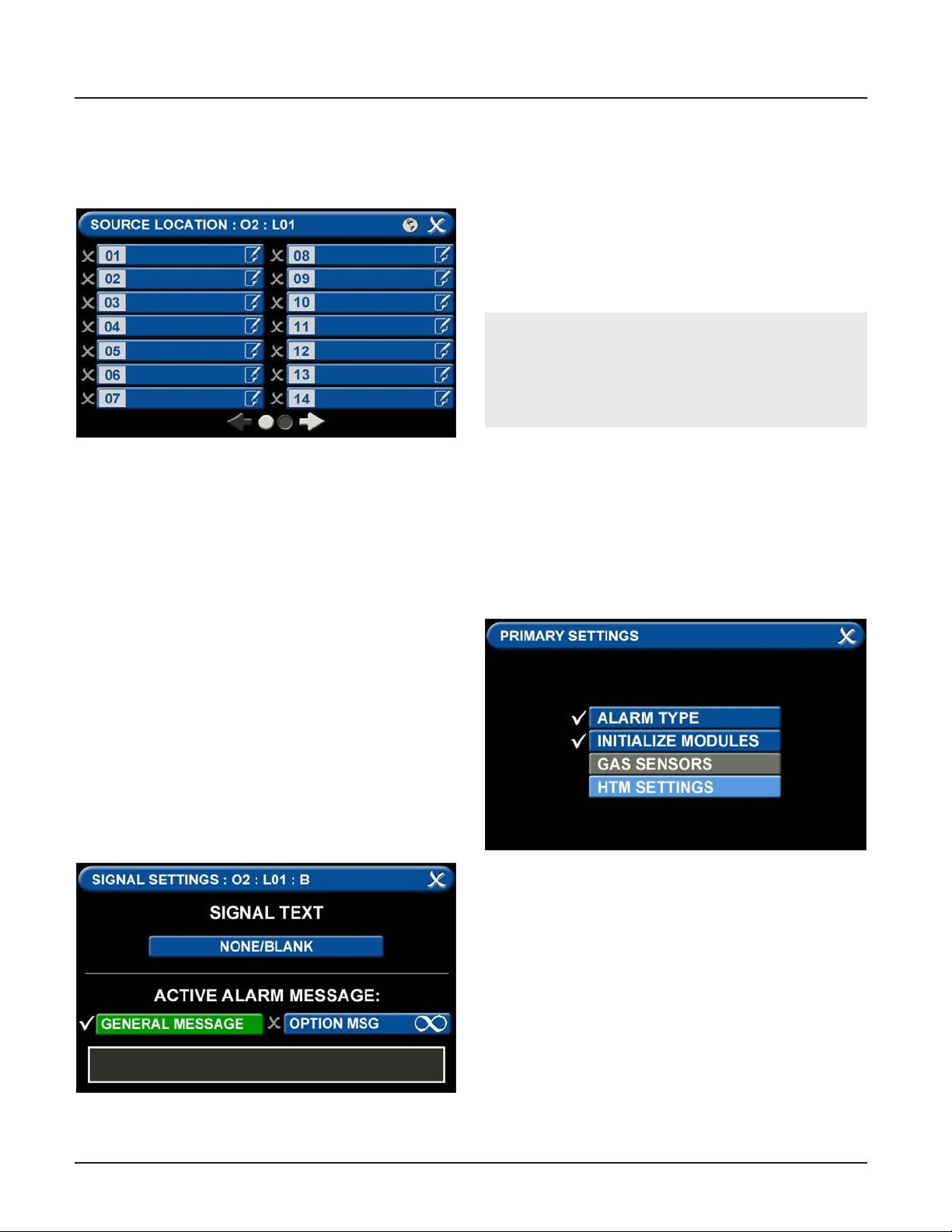
TotalAlert Innity™ HTM Medical Gas Notication System
letters and numbers.
4. Touch the Save button.
D = Area Monitored
Figure 163: Area Monitored
Touch the D = (Area Monitored) Tab
On the SOURCE LOCATION screen:
1. Touch the 01 tab. 1.
2. Using the keyboard, enter the name of the location
for the source equipment being monitored (e.g.,
ROOM 1). Enter multiple locations as needed (e.g.,
Manifold Room, Roof Top, Source Room).
3. Touch the Save button. A check appears when the
location is saved. Note: To edit the location, touch
the Pencil button.
4. Touch the X button to close and return to the
CONFIGURE (SOURCE) screen.
Each Plant (Source) badge has room for 4 signal inputs
(E-J) (Figure 4.85). The rst tab E is used to show the
alarm in “Normal” condition. The (F-H) inputs are used
for warning inputs such as “Change Cylinders” and ash
yellow when active. The last input (J) is used for the
fault condition and ashes red when in fault mode.
To select source signal input text:
1. Scroll through the options using the right and left
arrows at the bottom of the screen.
2. Touch the tab for the appropriate option, or select
a blank to create a custom alarm.
3. Touch the Save button when you see a check
beside your selection to close and return to the
SIGNAL SETTINGS screen.
4. Touch the X button in the upper right to close and
return to the CONFIGURE (SOURCE) screen.
Active Alarm Instruction:
To set facility instructions for active alarms, touch
either the GENERAL MESSAGE or OPTION MSG tab.
The alarm defaults to GENERAL MESSAGE. See
Section 4.6 for how to set up custom instructions.
4.8.4 Shire Network Setup
Go to the PRIMARY SETTINGS tab (from the conguration screen) to setup the HTM SETTINGS for the SHIRE
Network. (See Figure 4.153)
Figure 165: Shire Network Setup
Figure 164: Signal Settings Screen
4107 9016 60.01
• To communicate with a SHIRE network, press the
SHIRE COMMS tab.
4-46
Page 81
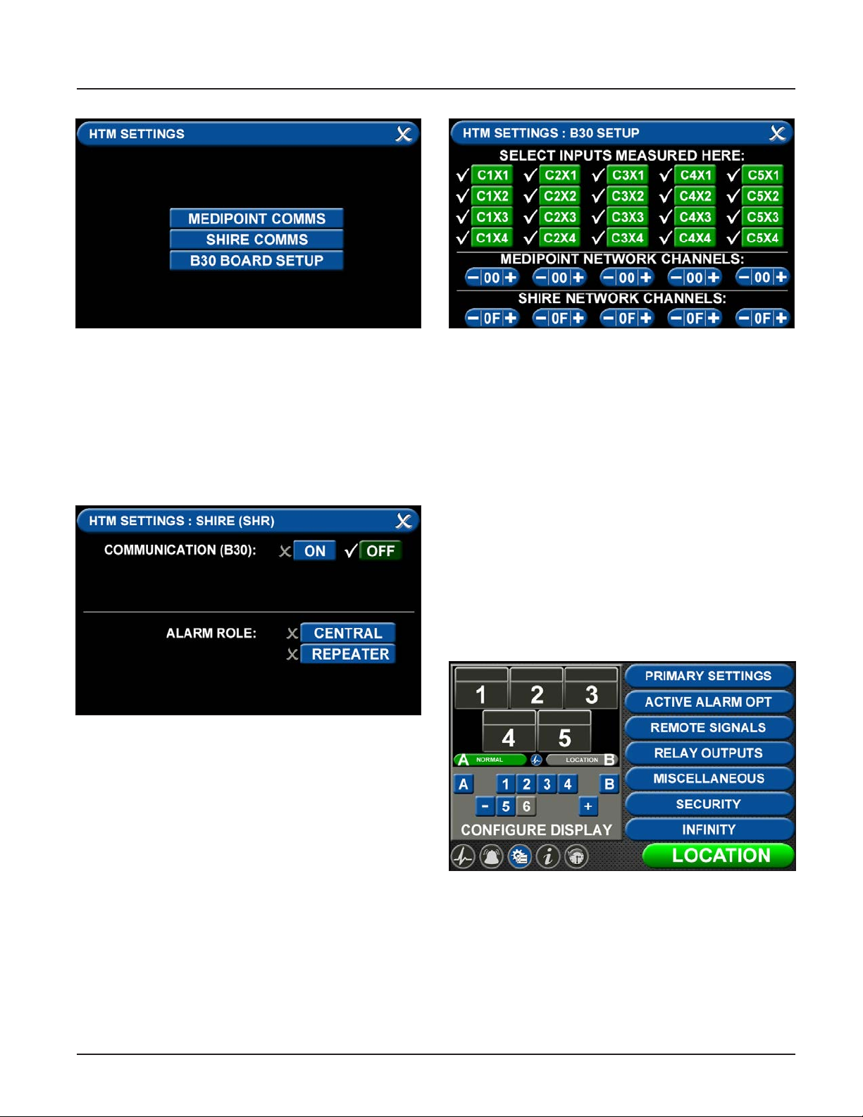
TotalAlert Innity™ HTM Medical Gas Notication System
Figure 166: Shire Network Setup
• Communication (B30) can be toggled OFF or ON by
pressing the correlating tabs. Alarm Role can also
be dened by selecting the CENTRAL or REPEATER
tabs. On a Shire network you select one device to
be the central, and all other devices on the shire
network are repeaters.
• Press save icon to complete setup.
Figure 167: Shire Network Setup
Figure 168: Shire Network Setup
• Select the inputs for signals that will be wired
locally to the alarm.
• Individual tabs can be toggled o and on by adding
or eliminating the check mark by the inputs where
you are landing the wires on the B30 board. Also, if
you are transmitting SHIRE signals, set the appropriate network channels by pressing the + or – tab
to the correct setting.
• Press save icon to complete setup.
4.8.5 Shire Network Gas Badge Setup
To setup gas badges to communicate on the SHIRE
network:
• Go to conguration screen and select the gas
badge.
• To transmit and recieve signals, the HTM Settings
tab has to be initialized (Figure 166).
• Press the B30 BOARD SETUP tab (Figure 167).
Figure 169: Conguration Screen
• Touch ALARM POINT tab to congure gas badge
4-47
4107 9016 60.01
Page 82
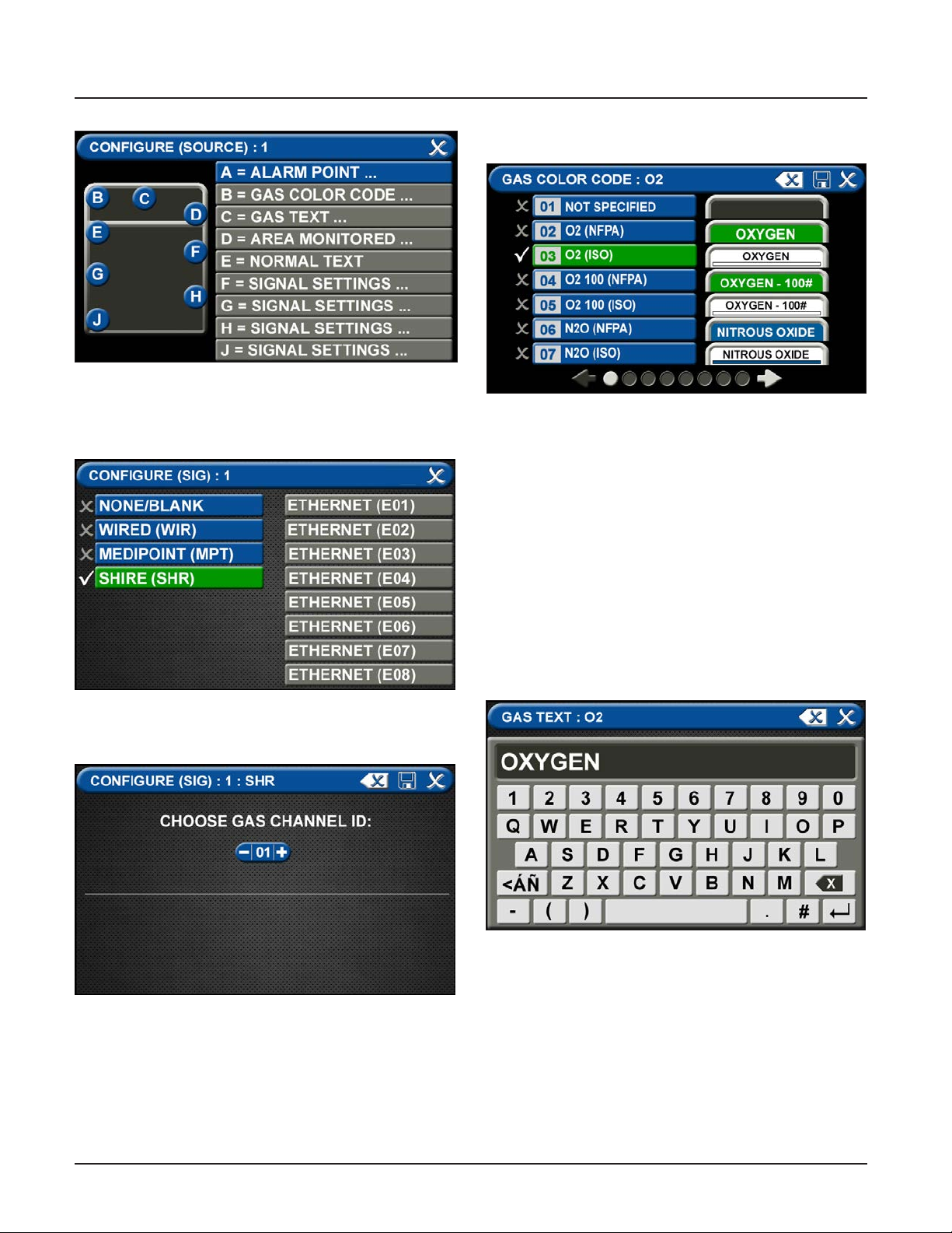
TotalAlert Innity™ HTM Medical Gas Notication System
B = Gas Color Code Tab
Figure 170: Congure Source Locations
A = Alarm Point Tab
• Touch ALARM POINT tab to congure gas badge
Figure 171: Congure Source Locations
• Select SHIRE (SHR) tab
Figure 173: Gas Color Code Tab
To select the color code for the appropriate gas based
on your standard and country:
1. Touch the B = GAS COLOR CODE tab (Figure 4.63)
2. Scroll through the gas types using the right and left
arrows at the bottom of the screen.
3. Touch the tab for the appropriate code, or select a
“custom” tab to create a unique source badge.
4. Touch the Save button when you see a check
beside your selection. This will automatically ll in
tabs C-J with default values for the gas selected. If
changes are needed follow the next steps below.
C = Gas Text Tab
Figure 172: Channel ID
• Use (-) and (+) to select the Gas Channel ID to be
displayed.
• Press Save Icon to complete setup.
4107 9016 60.01
Figure 174: Gas Text Keyboard
To add areas to be monitored:
5. Touch the AREA MONITORED tab.
6. Touch on the 01 tab.
Using the keyboard, enter the name of the area. To
change the name of the gas:
1. Touch the C = [GAS TEXT] tab.
2. Touch the Erase button on the keyboard to delete
the gas name.
3. Enter the new gas name. Touch the [<ÁÑ] to toggle
to symbols. Touch the [1AZ] key to toggle back to
4-48
Page 83
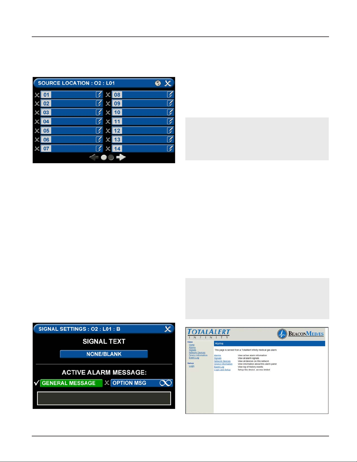
TotalAlert Innity™ HTM Medical Gas Notication System
letters and numbers.
4. Touch the Save button.
D = Area Monitored
Figure 175: Area Monitored
Touch the D = (Area Monitored) Tab
On the SOURCE LOCATION screen:
1. Touch the 01 tab. 1.
2. Using the keyboard, enter the name of the location
for the source equipment being monitored (e.g.,
ROOM 1). Enter multiple locations as needed (e.g.,
Manifold Room, Roof Top, Source Room).
3. Touch the Save button. A check appears when the
location is saved. Note: To edit the location, touch
the Pencil button.
4. Touch the X button to close and return to the
CONFIGURE (SOURCE) screen.
Each Plant (Source) badge has room for 4 signal inputs
(E-J) (Figure 4.85). The rst tab E is used to show the
alarm in “Normal” condition. The (F-H) inputs are used
for warning inputs such as “Change Cylinders” and
ash yellow when active. The last input (J) is used for
the fault condition and ashes red when in fault mode.
To select source signal input text:
1. Scroll through the options using the right and left
arrows at the bottom of the screen.
2. Touch the tab for the appropriate option, or select
a blank to create a custom alarm.
3. Touch the Save button when you see a check
beside your selection to close and return to the
SIGNAL SETTINGS screen.
4. Touch the X button in the upper right to close and
return to the CONFIGURE (SOURCE) screen.
Active Alarm Instruction:
To set facility instructions for active alarms, touch
either the GENERAL MESSAGE or OPTION MSG tab.
The alarm defaults to GENERAL MESSAGE. See
Section 4.6 for how to set up custom instructions.
4.9 Website
4.9.1 Navigating the Website
Accessing the Web Page
1. Start a web browser such as Microsoft Internet
Explorer.
2. Enter the Device’s IP address in the browser’s
address bar:
Example: http://10.10.5.10
3. After you enter the device name or IP address, the
alarm’s home page will be displayed.
NOTE:
To learn the IP address, touch the MISCELLANEOUS
tab on the conguration screen then touch the
WIRED ETHERNET tab.
Figure 176: Signal Settings Screen
4-49
Figure 177: Typical Alarm Panel Home Page
4107 9016 60.01
Page 84
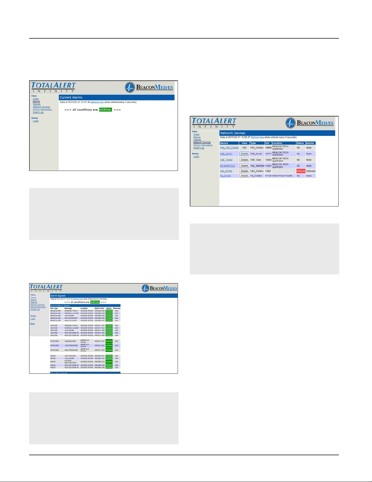
TotalAlert Innity™ HTM Medical Gas Notication System
Alarms
1. Click Alarms to view current alarms (Figure 4.159).
2. Click Refresh to view the most recent information.
Figure 178: Alarms Page
NOTE:
The Alarms page provides a snapshot of the current alarm conditions. If a new alarm occurs, the
page is not updated until the page is reloaded by
Autorefresh or by clicking on Alarms or Refresh
links.
Signals
1. Click Signals to view all local signals monitored by
this alarm panel (Figure 4.160).
2. Click Refresh to view the most recent information
Network Devices
1. To view all devices on the network, click Network
Devices (Figure 4.161).
2. Click Refresh to view the most recent information.
3. Click the Device link to jump to the home page of
the listed alarm.
4. Click the Details tab to show detailed information
about the device.
Figure 180: Network Devices Page
NOTE:
The Network Devices page provides a snapshot
of the current alarm network. If a device is added
to the network the page is not updated until the
page is reloaded by Autorefresh or by clicking on
Network Devices or Refresh links.
Figure 179: Alarm Signals Page
NOTE:
The Signals page provides a snapshot of the current alarm conditions. If a new alarm occurs, the
page is not updated until the page is reloaded by
Autorefresh or by clicking on Signals or Refresh
links.
4107 9016 60.01
Device Information
Click Device Information to view the Device Information
page (Figure 4.162).
Event Log
1. Click Event Log to view the Event Log page (Figure
4.162).
2. Click Refresh to view the most recent information.
3. To create a downloadable text le, click the Create
a Downloadable text le link.
4. Right click the link to save the event log to a le.
4-50
Page 85
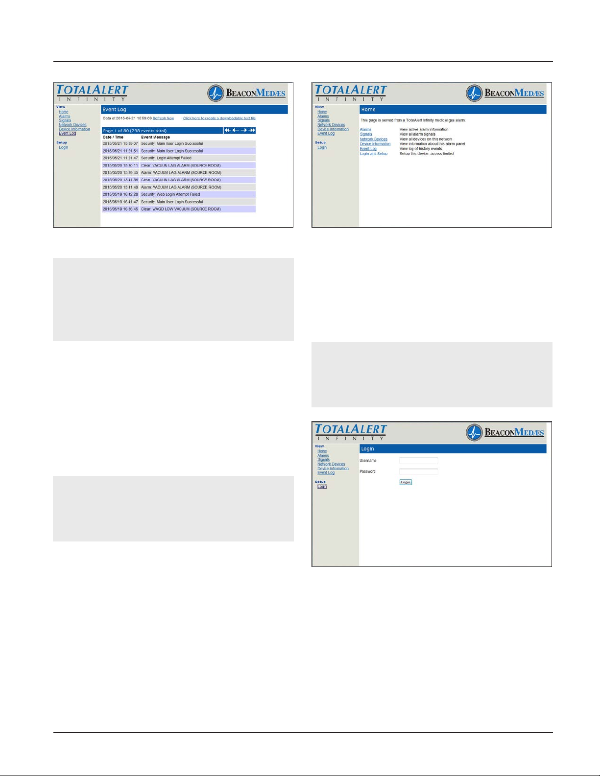
TotalAlert Innity™ HTM Medical Gas Notication System
Figure 181: Event Log
NOTE:
The Event Log page provides a snapshot of the
event log. If a new event occurs the page is not
updated until the page is reloaded by Autorefresh
or by clicking on Event Log or Refresh links.
Maximum number of logged events is 1000.
4.9.2 Website Set-Up
Accessing the Web Page
1. Start a web browser such as Microsoft Internet
Explorer.
2. Enter the Device’s IP address in the browser’s
address bar:
Example: http://10.10.5.10
NOTE:
To learn the IP address, touch the MISCELLA-
NEOUS tab on the conguration screen then touch
the WIRED ETHERNET tab.
Figure 182: Typical Alarm Panel Home Page
Login to Setup Pages
1. Click Login and Setup.
2. The web browser will request a username and
password (Figure 4.164). The factory defaults are:
Username: TotalAlert
Password: 1212123.
NOTE:
If the on-screen password has been changed from
the default password, use the newly assigned
password.
3. After you enter the device name or IP address, the
alarm’s home page will be displayed (Figure 4.163).
Figure 183: Login Dialog
3. The left sidebar will now contain the setup links
(Figure 4.165).
4-51
4107 9016 60.01
Page 86
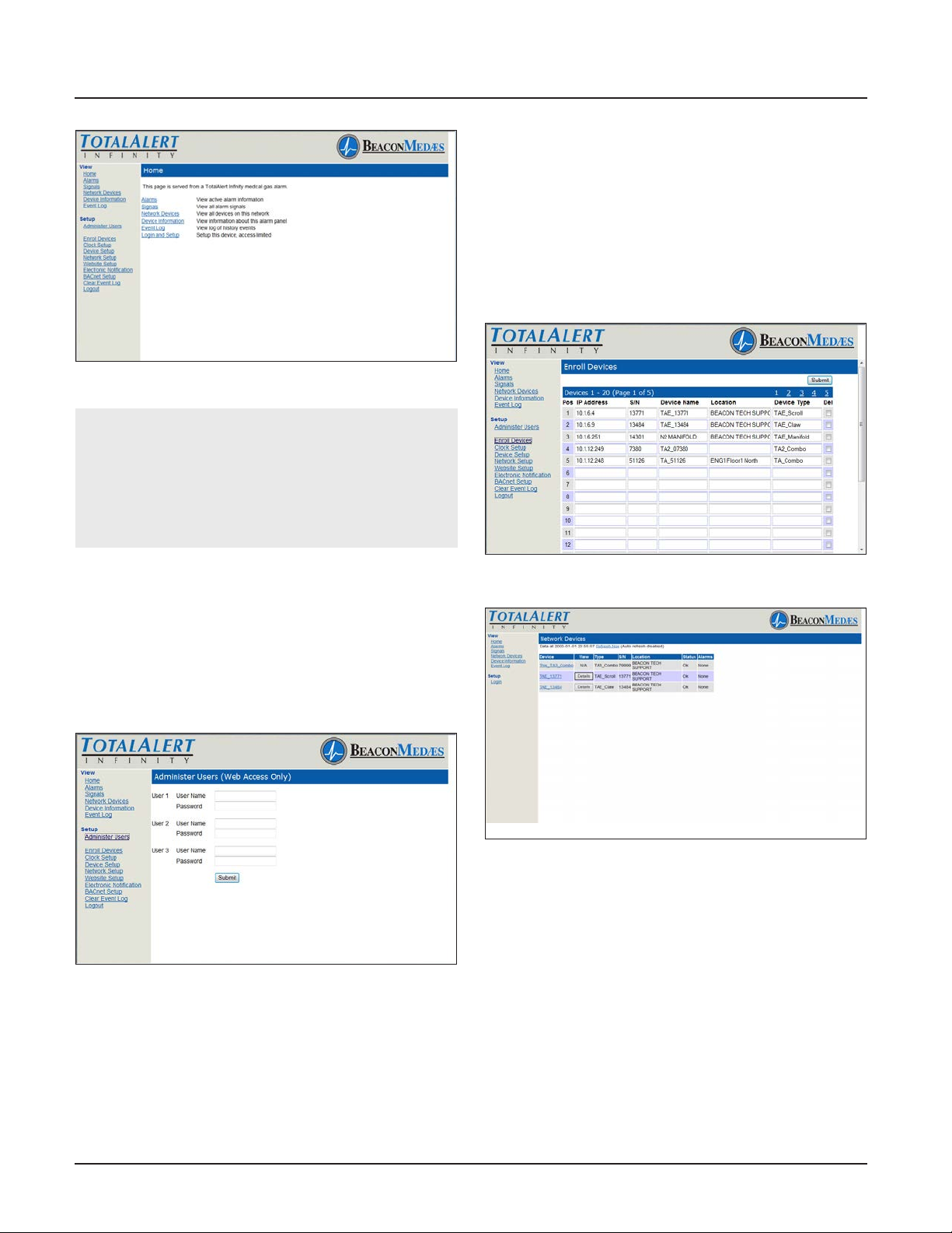
TotalAlert Innity™ HTM Medical Gas Notication System
and pressure reading) and which Area panel the condition is for.
1. Click on Enroll Devices to access the Enroll Devices
Setup page (Figure 4.167).
2. Enter the device IP address and Serial Number.
The Device Name, Location, and Device Type will
automatically ll (Network will refresh).
3. Click Submit.
4. To delete an enrolled device, click Del box of device
to delete and click Submit.
Figure 184: Logged In
NOTE:
Logging in applies only to the computer on which
the login occurs. If more than one PC is being used
to access the alarm web pages, each one must be
logged in individually. The computer stays logged
in until the user closes the browser.
Administer Users
Each TotalAlert Innity™ panel allows for three total
Administer Users
1. Click on Administer Users to access the Administer
Users Setup page (Figure 4.166)
2. Enter the User Name and Password then click
Submit.
Figure 185: Administer Users
Enroll Devices
The TotalAlert Innity™ provides the ability to enroll up
to 100 TotalAlert Embedded devices connected to the
medical gas network. Central and combination alarms
are the only alarms that allow for enrolled devices.
TotalAlert Innity™ Area alarms can now be enrolled via
Ethernet to the TotalAlert Innity™ central alarm. This
allows for the user to see the fault condition (gas type
Figure 186: Enroll Device Setup
Figure 187: Network Devices Screen
Set Clock
1. Click Clock Setup to access the Clock Setup page
(Figure 4.170).
2. Set the current date by inputting the year, month,
and day.
3. Set the current time by inputting the current hour
and minutes.
4. Click the SET tab to complete. When the SET tab is
pressed, the date and time are set on the system
and seconds are set to zero.
4107 9016 60.01
4-52
Page 87
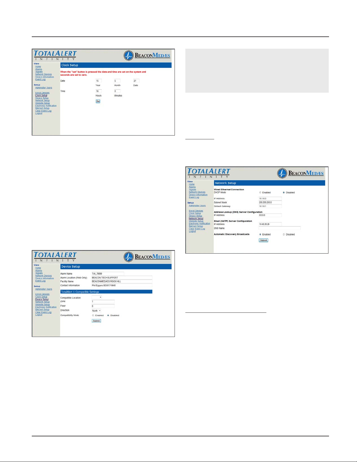
TotalAlert Innity™ HTM Medical Gas Notication System
CAUTION:
The Information Systems personnel should be notied before changing any of the network settings.
Changing the settings may prevent the equipment
from working properly.
Network Setup
1. Click Network Setup to access Network setup page
(Figure 4.172)
2. Select the DHCP Mode (Enabled/Disabled).
Figure 188: Clock Setup
Device Setup
This setup page is used to congure alarm name,
location, facility name, and contact information. The
page also provides input for TotalAlert1 compatibility if
the TotalAlert Innity™ needs to be enrolled on the
TotalAlert 1 network.
1. Click Device Setup to access the Setup Device page
(Figure 4.171).
2. Enter the Alarm name.
3. Enter the location.
4. Enter the facility name.
5. Enter the Contact Information.
6. Click Submit.
If Disabled:
1. Enter the IP Address.
2. Enter the Subnet Mask.
3. Enter the Default Gateway
Figure 189: Setup Device Page
To provide input for the TotalAlert 1 network:
1. Click Device Setup to access the Setup Device page
(Figure 4.171).
2. Select Compatible Location of the TotalAlert
Innity™ alarm by using pull down menu.
3. Enter the Area for the TotalAlert Innity™.
4. Enter Floor location.
5. Enter Direction.
6. Enter Compatibility Mode.
7. Click Submit.
Figure 190: Network Setup Page
The TotalAlert Innity™ Alarm allows for Automatic
Discovery Broadcast on other TotalAlert devices. This
setting allows for other TotalAlert devices to nd the
TotalAlert Innity™ alarm on the network and automatically enroll the device.
To enable Automatic Discovery:
1. Select Enabled on the Network Setup page to set
Automatic Discovery Broadcasts.
2. Click Submit.
Website Setup
The TotalAlert Innity™ Website has several options
for the Auto-refresh feature on the web page. This
determines the frequency by which Status pages are
automatically updated.
1. Click Website Setup to access Auto-refresh time
menu (Figure 4.178 from 5 seconds to 4 minutes to
refresh. Select Disable to remove Auto-refresh and
manually update data when needed.
2. Click Submit.
4-53
4107 9016 60.01
Page 88
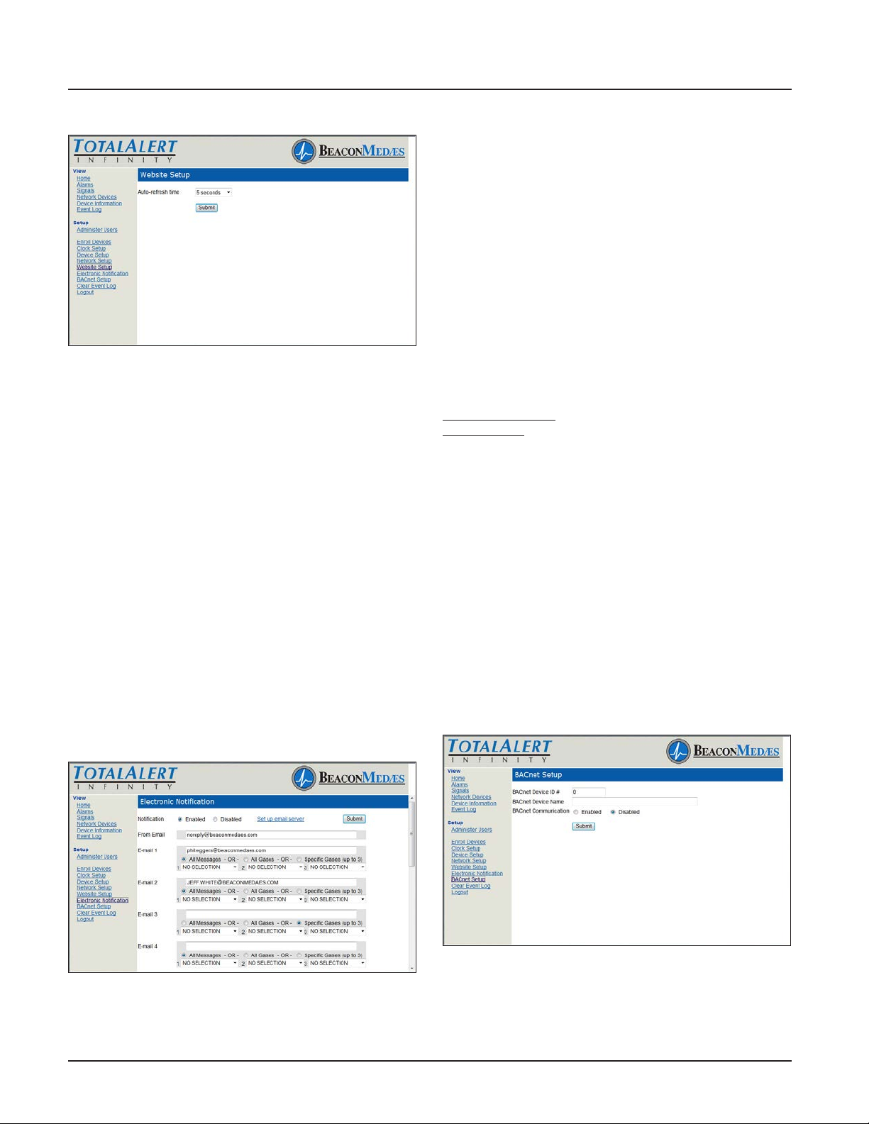
TotalAlert Innity™ HTM Medical Gas Notication System
BACnet Setup
The BeaconMedæs TotalAlert Innity™ HTM control
systems utilize the TCP/ IP family of protocols for
communication and each alarm has a unique IP
address.
Each BACnet enabled TotalAlert Innity™ alarm
conforms to the BACnet protocol.
• Protocol Implementation Conformance
Each BACnet enabled TotalAlert Innity™ alarm has
available a Protocol Implementation Conformance
Statement (PICS). The PICS is a written document
created by BeaconMedæs that identies the particular
Figure 191: Website Setup Page
Electronic Notication
This setup page is used to congure electronic notication (e-mail, pager, phone text message). The
alarm panel acts as an SMTP client. An SMTP server is
required for electronic notication to function. The TotalAlert Innity™ website has the ability to setup email
notication for all messages, all gases, or specically up
to 3 gases.
By setting up the Electronic Notication, key personnel
can receive notications of all alarm events.
An SMTP e-mail server must be congured in order for
Electronic Notications to function. Click “Set Up Email
Server” to congure the server (Figure 4.179).
1. Click Electronic Notication to access the Electronic
Notication setup page (Figure 4.180).
2. Enter an e-mail address. Up to twelve e-mail
addresses can be set up.
3. Choose All Messages, All Gases, or Specic Gases
(up to 3) from pull down menu.
4. Click Submit.
options specied by BACnet that are implemented in
the TotalAlert Innity™ alarm.
• BACnet Conformance
BACnet Vendor ID: 543
Alarm Prole: BACnet Smart Sensor (B-SS)
BIBB (BACnet Interoperability Building Blocks)
Supported:
• Read Property - B (DS-RP-B)
• Dynamic Device Binding - B (DM-DDB-B)
• Dynamic Object Binding - B (DM-DOB-B)
Object Type Support: Analog value, Binary value,
Device.
Data Line Layer Options: ISO 8802-3 (“Ethernet”) LAN
Character Set Support: ISO 10646 (UTF-8) Encoding.
1. Click BACnet Setup to access BACnet Setup page
(Figure 4.157).
2. Enter BACnet Device ID#.
3. Enter BACnet Device Name.
4. Choose to Enable or Disable BACnet
Communication.
5. Click Submit
Figure 192: Electronic Notication Setup Page
4107 9016 60.01
Figure 193: BACnet Setup Page
4-54
Page 89
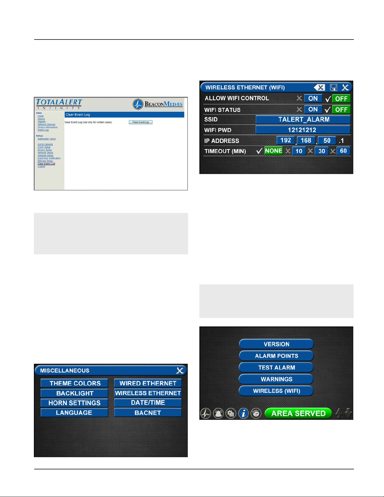
TotalAlert Innity™ HTM Medical Gas Notication System
Clear Event Log
1. Click Clear Event Log to access the Clear Event Log
page (Figure 4.180).
2. Click Clear Event Log.
Figure 194: Clear Event Log
CAUTION:
Be sure to save the event log prior to clearing it.
It is impossible to recover the event log after it is
cleared.
4.10 Wireless Ethernet Set-Up
The TotalAlert Innity™ Medical Gas Notication
System allows for Wi 802.11 b/g/n interface which
provides access to the alarm panel web page with any
web enabled device. Operating information and Event
History can be viewed and downloaded to the web
enabled device.
Wireless Ethernet Settings Tab
On the Miscellaneous screen, select the WIRELESS
ETHERNET tab.
The WIRELESS ETHERNET screen allows for customization of the WIFI settings. All of the tabs on this screen
are set to default status.
Figure 196: Wireless Ethernet Screen
• Touch the WIRELESS ETHERNET tab.
• To turn the WIFI on, touch the WIFI STATUS/ ON
tab.
• To change the WIFI password—STRONGLY
RECOMMENDED—touch the WIFI PWDtab. Using
the keyboard, enter a new password.
• Touch the Save button to close and return to the
WIFI SETTINGS screen.
• To add the WIFI settings to the INFORMATION
screen, touch the ALLOW WIFI CONTROL / ON tab.
The INFORMATION screen will now display a WIFI
tab (Figure 4.184).
NOTE:
This will allow WIFI to be turned on/o without a
password.
Figure 195: Wireless Ethernet Tab
Figure 197: Wireless Ethernet Screen
• Save settings.
• Turn on the Web enabled device.
• Find the wireless Ethernet network on the device
with the SSID name.
4-55
4107 9016 60.01
Page 90

TotalAlert Innity™ HTM Medical Gas Notication System
• Type in the password (default is 121212) on the
web enabled device.
• Open the browser and enter the IP address (default
is 192.168.50.1) to go to the TotalAlert Innity™
home page. This page displays active alarms, gas
pressure signals, Network devices, device information, and the event log.
4107 9016 60.01
4-56
Page 91

TotalAlert Innity™ HTM Medical Gas Notication System
4-57
4107 9016 60.01
Page 92
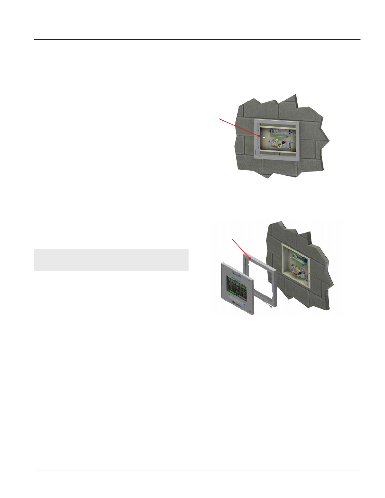
TotalAlert Innity™ HTM Medical Gas Notication System
5.0 Retrot
5.1 Retrot of MP26 or MP125
Concealed Mounted Alarm Panels
5.1.1 Remove Components from Existing
Alarm
1. Open the old alarm panel to be retrotted and
ensure that the retrot kit to be installed is correct
according to the number of Signal inputs, Relay
outputs, and/or Gas Sensor signals (See Appendix
A).
2. Test Central and Area alarm signals to validate
wiring and document all signal wires coming into
the box with alarm type and locations prior to
disconnecting. This information will be required to
setup the new alarm.
3. Turn o the supply power to the alarm.
4. Disconnect the ribbon cable(s) to the panel door
and remove. Remove Trim Plate.
5. Disconnect all labeled wiring from the PCB and
remove the PCB and all other removable hardware
and spacers.
5.1.2 Install New Components
1. Install the Trim Ring to the concealed backbox
using the previous hinge screws (Figure 5.1).
Trim Ring
Figure 5.1: MP26 Retrot Installation
Trim Ring
CAUTION: Verify that power has been turned o
prior to working on the alarm.
Figure 5.2: MP125 Retrot Installation
2. Install the new power supply on the existing top
two studs in the backbox (note the position of the
green terminal block in reference to the Mains
Power).
3. Install additional module on the existing bottom
two studs in the backbox. For MP125, use the
supply adapter bracket to mount the module.
4. Locate the Earth cable from the power supply and
fasten it to the Earth stud on the backbox.
5. Remove the four screws from the power supply
plastic shield and remove the shield.
5-1
4107 9016 60.01
Page 93
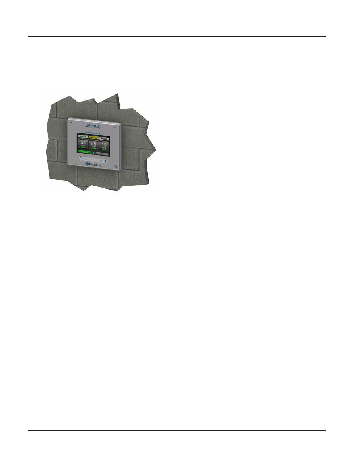
TotalAlert Innity™ HTM Medical Gas Notication System
6. Connect the Live and Neutral wires to the terminal
block on the power supply and the Mains Earth to
the Earth stud on the backbox.
7. Place the power supply shield back in place,
ensuring that all high voltage wires are secured
behind the cover and install the four corner screws.
Figure 5.3: Front Panel Mounting
Central Wiring
1. For retrot of a Central alarm panel the existing
BeaconMedaes Line Monitoring contact wires
can be connected to the appropriate terminal
block locations on the B30 board along with any
Medipoint or Shire communication wires. Refer to
HTM Central Wiring Diagram (Section 3.1).
Remote Sensors
1. New TotalAlert Innity Digital Gas Sensors must be
installed to work with the TotalAlert Innity alarm
panel.
2. CAUTION: If Orice tting is not installed at the
sensor connection, ensure that the pressure on
the pipeline in the alarm area has been released
before removing any components from the
pipeline connection.
3. Remove existing pressure switch from the hospital
pipeline and disconnect eld wiring.
4. Install new digital gas sensor in the pipeline port.
5. Remove the strain relief and housing from the gas
sensor to access the terminal block. Insert eld
wiring through strain relief and housing,
connecting to the terminal block. Note the polarity.
6. Reinstall housing and strain relief and tighten cord
grip to secure eld wiring.
7. Return pressure to the hospital pipeline and check
sensor connections for leaks.
Area Wiring
1. Connect all the gas sensor wires to the appropriate
terminal block locations on the B60 board, noting
polarity. Refer to HTM Area Wiring Diagram
(Section 3.2).
5.1.3 Install Second Fix Kit
1. Install the Front display panel to the trim ring at the
bottom hinge using the screws provided.
2. Connect the lanyard to the threaded stando
on the trim ring and secure with M4 nylock nut
provided. Note: Do not tighten nut all the way, the
lanyard eyelet should move freely when opening
and closing the front display panel.
3. Connect the green Earth wire on the front display
panel to the existing Earth stud in the backbox.
4. Connect the grey RS-485 communication cable
provided on the front display panel to the power
supply.
5. Turn on the Mains power to the alarm and wait for
the alarm to boot up.
6. Setup the new alarm by referring to the Quick
Setup Guide.
4107 9016 60.01
5-2
Page 94
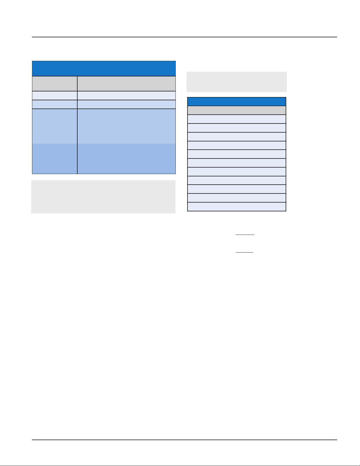
TotalAlert Innity™ HTM Medical Gas Notication System
Appendix A:
Variable B
Alarm Type and Size
Allowable
Description
Value
B00 Blank
A10 Area Alarm, Up to 8 Area Gases
M01 Master, 0 Inputs, 16 Relay Outputs
M02 Master, 0 Inputs, 32 Relay Outputs
M10 Master, 20 Inputs
M11 Master, 20 Inputs, 16 Relay Outputs
C10 Combination, up to 20 Inputs, Display
up to 6 Area Gases
C40 Combination, 6 Relay Outputs and up
to 4 Inputs for 4-20mA devices
NOTE:
Standard congurations listed above. For special
congurations contact BeaconMedaes Customer
Service +44 (0) 1246 474 242.
Notes:
* Limitations on Combination Panels:
• C10, C11, C12 Combinations
x 0-10 source signal Inputs used, Display up to 6 Area gases
x 11-20 source signal Inputs used, Display up to 4 Area gases
• C40
x 0-20 source signal Inputs used, Display up to 4 4-20mA devices
x 21-27 source signal Inputs used, Display up to 2 4-20mA devices
Retrot Alarm Models
A3- ___ - R
A
Available Gas Sensors
Description
Oxygen
Nitrous Oxide
Medical Air
Medical Vacuum
Nitrogen
Carbon Dioxide (CO2)
HE-O2 (HE over 80%)
Laboratory Air
Laboratory Vacuum
Surgical Air
O2-N2O
Example: TotalAlert Innity™ Central Alarm with 20 Inputs and 16 Relay
Outputs
Example Model Number: A3-M11-R
Example: TotalAlert Innity™ Area Alarm with four gases - Oxygen, Nitrous
Oxide, Medical Air, and Vacuum
Example Model Number: A3-A10-R
5-3
4107 9016 60.01
Page 95
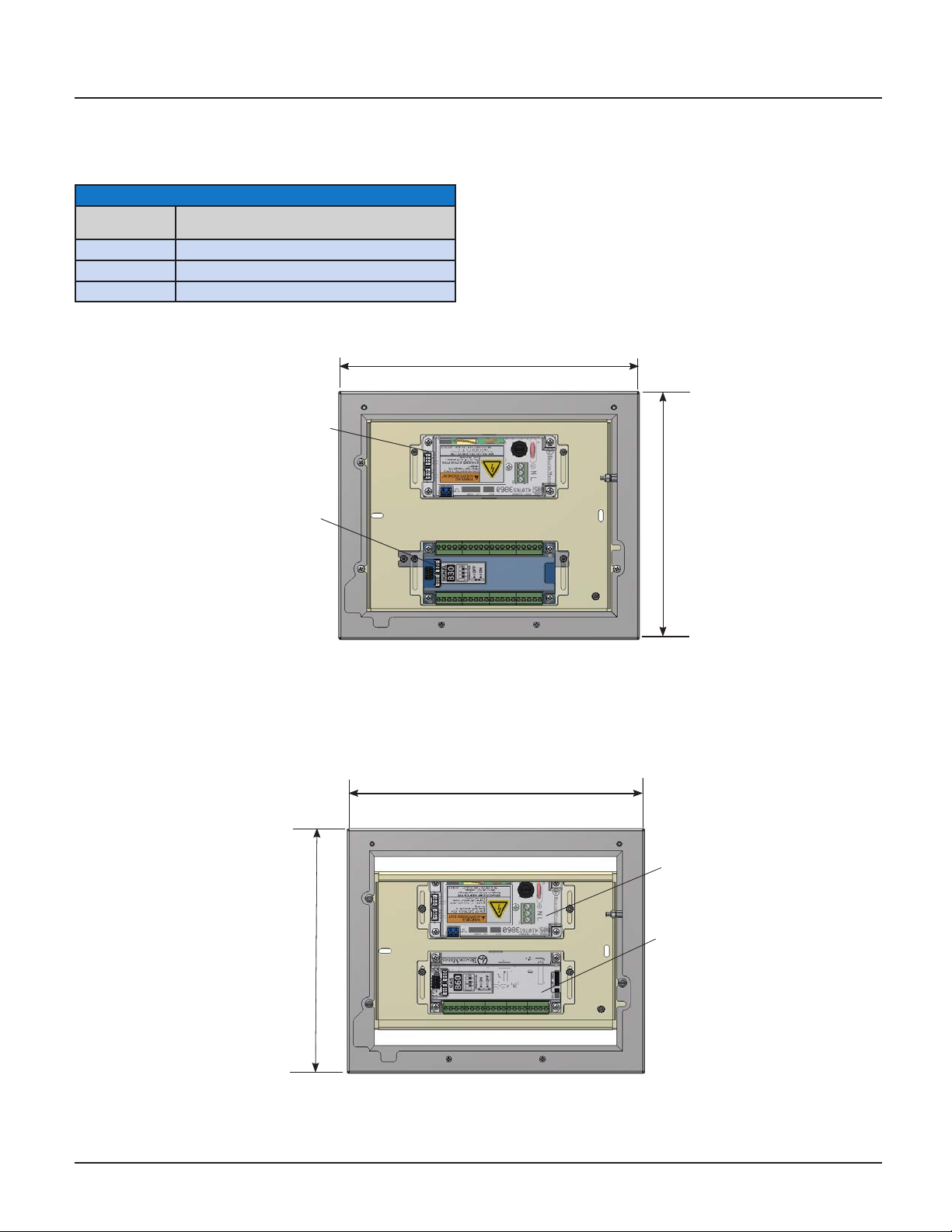
TotalAlert Innity™ HTM Medical Gas Notication System
Typical Retrot Layouts
(Recommended Installation)
Module Components
Letter
Designator
A B05 Power Supply
B B30 Module (Signals, 20 Inputs)
C B60 Module (Gas Input, 8 gases, 1 output)
Description
Dimensions
B
282mm
A
232mm
MP125 Retrofit
282mm
4107 9016 60.01
232mm
A
C
MP26 Retrofit
5-4
Page 96
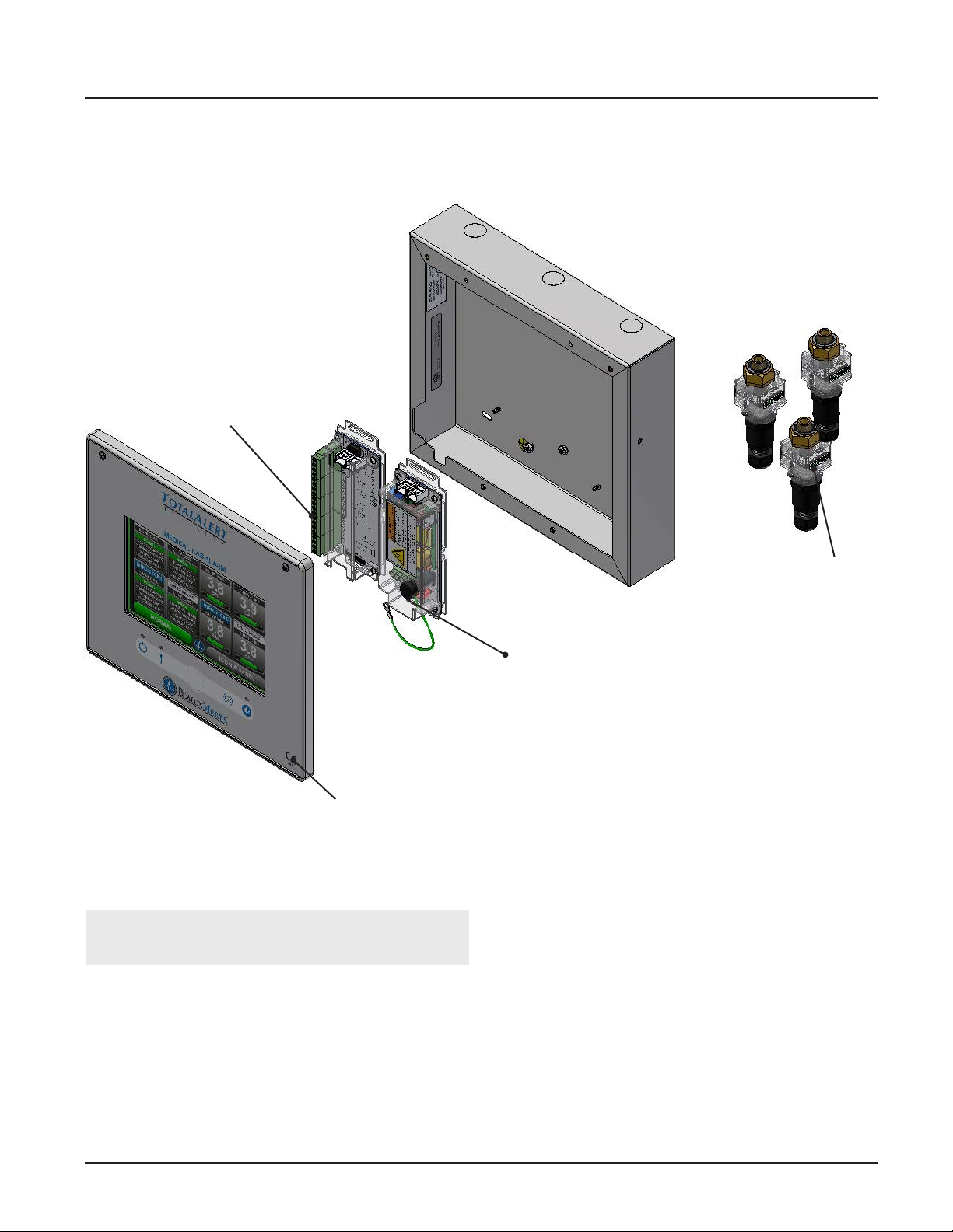
TotalAlert Innity™ HTM Medical Gas Notication System
6.0 Maintenance
I/O Board*
See Table 2 for complete list
Front Panel Assembly
Figure 6.1: Maintenance
NOTE: For additional service parts, see parts list
manual (Part #4107 9017 56).
Gas Sensor
Module**
See Table 1
Power Supply
6-1
4107 9016 60.01
Page 97
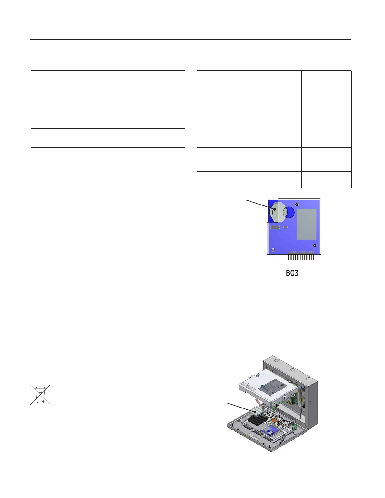
TotalAlert Innity™ HTM Medical Gas Notication System
*Table 1: Gas Sensor Module Options
(Service replacement only)
Part Number Gas Sensor Assembly
4107 2131 25 O2 Sensor Assembly
4107 2131 26 N2O Sensor Assembly
4107 2131 28 MedAir Sensor Assembly
4107 2131 32 MedVac Sensor Assembly
4107 2131 35 N2 Sensor Assembly
4107 2131 30 CO2 Sensor Assembly
4107 2131 31 HE-O2 Sensor Assembly
4107 2131 29 LAB-AIR Sensor Assembly
4107 2131 33 LAB-VAC Sensor Assembly
4107 2131 34 Surgical Air Sensor Assembly
4107 2131 27 O2-N2O Sensor Assembly
Cleaning:
Use clean dry microber cloth or soft lint-free cloth
to remove any smudges located on the touchscreen.
Make sure not to apply too much pressure on the
screen when cleaning it. Never use paper towels or
tissue paper which contain wood bers that will scratch
any plastic surface.
**Table 2: I/O Boards
(Service replacement only)
Part Number I/O Boards Description
4107 4016 36 B03 Advance
Module
4107 4016 37 B05 Power Module Power supply
4107 4016 40 B30 (HTM Signal
Input Board)
4107 4016 41 B4X (Relay Board) 16 Relay
4107 4016 42 B50 (4-20mA
Combination
Board)
4107 4016 43 B60 (Gas Input
Board)
Advanced
features board
20 Line Contact
Monitoring
Inputs
Outputs
4 Inputs for
4-20mA Signals
8 Gases
Coin Cell
Battery
Periodic Maintenance:
Inspect the alarm periodically and perform a self test
(see Section 4.1.6 - Information Screen). This ensures
proper operation of the alarm. Any damaged components inside the alarm should be replaced by an
authorized BeaconMedæs service technician.
For TotalAlert Innity
ment Kit by calling Customer Service at 1-800-4MEDGAS.
™
alarms, Order Service Replace-
Batteries:
The backup batteries and the coin cell battery on
the Advanced Module needs to be replaced every 5
years.
Do Not Dispose of in General Waste”
Follow local ordinances related to the proper disposal of batteries.
Figure 6.2: Coin Cell Battery
Backup Battery Testing:
Open front panel and locate the grey power cable connecting to back of front panel. Disconnect grey cable
from front panel (power will be removed at this point).
If batteries are working, power LED light located on
front panel will be on. If power LED light is not on, bat-
tery’s need to be replaced.
Backup
Battery
Pack
4107 9016 60.01
Figure 6.3: Rechargable Battery
6-2
Page 98
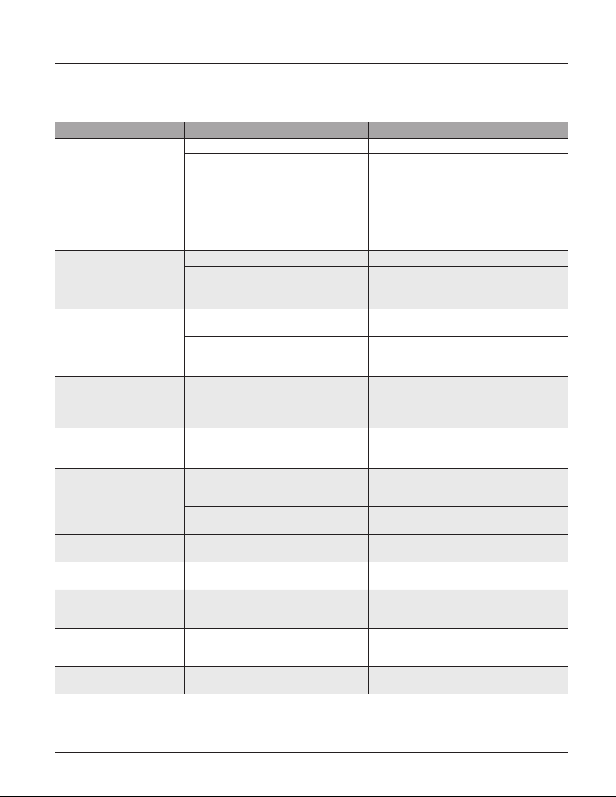
TotalAlert Innity™ HTM Medical Gas Notication System
7.0 Troubleshooting
Symptom Possible Cause Corrective Action
No LED power indicator
illuminated on alarm
front panel
No green “heartbeat”
power indicator is
illuminated on
connected boards
No green “heartbeat”
power indicator is
illuminated on gas
sensor
Fast green "heartbeat"
power indicator is illuminated on gas sensor
(2 beats per second)
Red LED illuminated
above warning
indicator ( ! ).
Lost Connection
Warning
Sensor active and
Unassigned Warning
F1 displayed on Area
badge
F2 displayed on Area
badge
F3 displayed on Area
Badge
F4 displayed on Area
Badge
AC power is not turned on Check AC power source.
Blown power supply fuse Replace fuse.
AC power wiring is not connected Check AC entrance wiring at power supply
terminals.
Power supply DC wire harness is not
connected properly between the power
supply and the main board
Faulty power supply assembly Replace power supply
Board has not been initialized Initialize board per instructions in manual.
Board dip switches are not set
correctly.
Cable not connected correctly Check cable connections between boards.
Sensor not connected to the Gas Input
Board.
Gas Input Board does not have power
(no “heartbeat”)
Sensor is reading out of range Verify gas pressure in pipeline. If normal,
Active warning Navigate to the warning screen by
Alarm has lost network communication
with manually enrolled device
The alarm has lost connection to a
connected/ initialized board.
Sensor is wired to the sensor input
board, but not assigned/programmed
Gas sensor is not connected or has
shorted.
Gas sensor is reading below range
(fault low).
Gas sensor is reading above range
(fault high).
Gas sensor connected is wrong type of
gas.
Check connections on each end including
orientation of cable connectors. Reconnect
if necessary.
Set dip switches per diagram on board
label.
Verify correct sensor connection to Gas
Input Board.
Verify that Gas Input Board has been
initialized and that dip switches are set
correctly. See item 2 above.
replace sensor.
pressing the Information button, then
selecting Warnings.
Correct communication problem with
networked device or remove the enrolled
device from the Enrolled Devices list.
Check connections and cable to board.
Assign the wired gas sensor to a valid gas
input.
Check gas sensor connection. If connection
is good, replace sensor.
Verify gas sensor connections and pipeline
pressure. If connection and pressure are
good, replace sensor.
Verify gas sensor connections and pipeline
pressure. If connection and pressure are
good, replace sensor.
Connect the correct type gas sensor.
7-1
4107 9016 60.01
Page 99
TotalAlert Innity™ HTM Medical Gas Notication System
Troubleshooting (continued)
Symptom Possible Cause Corrective Action
Area Display pressure/
vacuum reading not
matching pipeline.
Bad gauge on pipeline Verify gauge used on pipeline
Incorrect unit of measure Check unit of measure, if incorrect,
reprogram unit of measure.
Gas sensor out of calibration Adjust Zero Oset to correct reading.
(Note: there is a max oset of ±0.3
bar/60 mmhg). If sensor cannot be
adjusted enough, replace sensor.
High or Low alarm, with
normal pressure
displaying on Area
display
Screen is blank, power on
LED is illuminated
Audible alarm does not
reactive after 15 minutes
Alarm set points have been changed. Verify / correct alarm set points.
Screen backlight will time out and
shut o. Motion sensor will awaken
screen when motion is sensed within
5 ft of screen.
Maintenance mode has been entered
without correcting all alarm
conditions.
If screen does not awaken when
approaching alarm, touch screen to
awaken. Possible faulty motion sensor.
Turn Maintenance mode to OFF.
4107 9016 60.01
7-2
Page 100
TotalAlert Innity™ HTM Medical Gas Notication System
8.0 Central Alarm Signal Input Data
Module Board Input Alarm Message Source Location
C1X1
C1X2
C1X3
C1X4
C2X1
C2X2
C2X3
B30
C2X4
C3X1
C3X2
C3X3
C3X4
C4X1
C4X2
C4X3
C4X4
C5X1
C5X2
C5X3
C5X4
8-1
4107 9016 60.01
 Loading...