

Page 1
Installation, Operation, and Maintenance Instructions
6-847718-00 Rev. B00
Page 2

Page 3

1
6-847718-00 Rev. B00
Introduction
Product Identification......................................................................................................4
Alarm Modular Components...........................................................................................5
Annunciator Module .................................................................................................5
Multiplexer Module ...................................................................................................5
LED Module..............................................................................................................5
Breakout Board ........................................................................................................5
Relay Board..............................................................................................................6
Digital Display Module..............................................................................................6
Multi-Signal Module..................................................................................................6
Blank Module............................................................................................................6
Definition of Statements .................................................................................................7
Definitions.......................................................................................................................7
Alarm Configurations....................................................................................................10
Master Alarms.........................................................................................................11
Area Alarms............................................................................................................12
Combo Alarms........................................................................................................14
Electromagnetic Compatibility ......................................................................................16
FCC ........................................................................................................................16
ICES-003................................................................................................................16
EN 60601-1-2 .........................................................................................................16
Installation Overview
Master Alarms ........................................................................................................21
Area Alarms............................................................................................................21
Combo Alarms........................................................................................................22
Installation Procedures
Rough-In.......................................................................................................................23
Alarm Panel Back Box ...........................................................................................23
Remote Sensor Back Box ......................................................................................24
Pipeline Connection ...............................................................................................25
Pull Wire .......................................................................................................................27
General Requirements ...........................................................................................27
Wire Type And Size ................................................................................................27
Wire Routing...........................................................................................................28
Determining Number Of Conductors......................................................................29
Wiring ...........................................................................................................................30
Power Supply .........................................................................................................30
Remote Sensor ......................................................................................................31
Breakout Board Inputs............................................................................................32
Relay Board Outputs..............................................................................................33
Multi-Signal Module Inputs.....................................................................................34
Digital Display Module Master/Slave......................................................................35
Multi-Signal Module Relays....................................................................................35
General Fault / Aux Relays ....................................................................................36
Digital Display Module High / LowRelays ..............................................................36
Ethernet..................................................................................................................37
Building Automation System ..................................................................................37
Contents
Page 4

2
6-847718-00 Rev. B00
Contents
Field Wiring Cable Shield Grounding .....................................................................39
Finish............................................................................................................................40
Front Panel Mounting.............................................................................................40
Local Sensor ..........................................................................................................41
Remote Sensor ......................................................................................................42
Labeling..................................................................................................................43
Wiring Schematics
Wiring Schematic 1: Power Supply.............................................................................46
Wiring Schematic 2: Sensor Module to Digital Display Module..................................47
Wiring Schematic 3: Multiplexer / Breakout Boards....................................................48
Wiring Schematic 4: Relay Board ...............................................................................49
Wiring Schematic 5: Multi-Signal Module Inputs.........................................................50
Wiring Schematic 6: Digital Display Module Master/Slave .........................................51
Wiring Schematic 7: Multi-Signal Module Relay Outputs ...........................................52
Wiring Schematic 9: Digital Display Module High / Low Relays ..................................53
Wiring Schematic 8: General Fault / Auxiliary Relays ................................................53
Wiring Schematic 10: Remote Pressure / Vacuum Switches .....................................54
Wiring Schematic 11: Johnson Controls Metasys® N2 Connection ...........................55
Operation
Start-Up and Checking .................................................................................................56
Master Alarm Panel................................................................................................56
Area Alarm Panel ...................................................................................................57
Combo Alarm Panel ...............................................................................................58
Set-Up Procedures.......................................................................................................59
Annunciator Module ...............................................................................................59
Multiplexer Module .................................................................................................62
Digital Display Module............................................................................................64
Digital Display Module-Advanced...........................................................................66
Multi-Signal Module................................................................................................69
Multi-Signal Module-Advanced...............................................................................70
Set-Up Network Interface.............................................................................................72
Set-Up Using Web Pages ............................................................................................76
Accessing the Web Page .......................................................................................76
Login in to Setup Pages .........................................................................................77
Enroll Devices ........................................................................................................78
Setup Alarm Messages ..........................................................................................80
Setup Area Alarms .................................................................................................84
Setup Device ..........................................................................................................86
Electronic Notification.............................................................................................88
Electronic Notification - Server Setup ....................................................................89
Set Clock ................................................................................................................90
Administer Users ....................................................................................................91
Setup Network........................................................................................................92
Clear Network.........................................................................................................94
Clear Event Log .....................................................................................................96
Transfer Setup........................................................................................................98
Monitoring Mode.........................................................................................................100
Page 5

3
6-847718-00 Rev. B00
Annunciator Module .............................................................................................100
Multiplexer / LED Module .....................................................................................101
Digital Display Module..........................................................................................101
Multi-Signal Module..............................................................................................102
Browsing Alarm Web Pages.......................................................................................103
Accessing the Web Page .....................................................................................103
Current Alarms .....................................................................................................104
Signals..................................................................................................................105
Network Devices ..................................................................................................106
View Device..........................................................................................................107
Device Information ...............................................................................................108
Event Log .............................................................................................................109
Diagnostics ...........................................................................................................110
Download Configuration .......................................................................................111
Network Statistics .................................................................................................112
Testing
Alarm System .............................................................................................................114
Annunciator Module....................................................................................................114
Multiplexer Module .....................................................................................................116
Digital Display Module ................................................................................................117
Multi-Signal Module ....................................................................................................118
Power Supply .............................................................................................................119
Troubleshooting
Troubleshooting Guide ...............................................................................................120
Replacement Parts
Front Panel Components - Area Alarm ......................................................................129
Front Panel Components - Master Alarm...................................................................130
Front Panel Components - Combo Alarm ..................................................................131
Back Box Components - Area Alarm..........................................................................132
Back Box Components - Master / Combo Alarm .......................................................133
Breakout and Relay Board Components - Master / Combo Alarm ............................134
Sensor Components...................................................................................................135
Labeling......................................................................................................................136
Field Installation Kits ..................................................................................................136
Notes ...............................................................................................................................137
Master Alarm Signal Input Data ....................................................................................138
Warranty..........................................................................................................................140
Contents
Page 6
4
6-847718-00 Rev. B00
Product Identification
Introduction
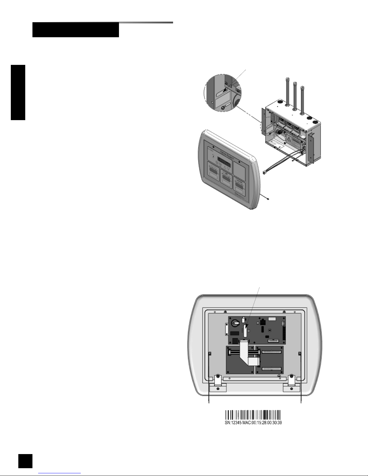
Each alarm is identified by a model number, lot code and serial number.
Installation procedures vary depending on
the alarm configuration.
The model number/lot code label is located
on the inside of the alarm back box
(Figure 1).
The serial number is located on the annunciator module board (Figure 2).
Figure 2: Product Serial Number
Serial number label
Model number/lot code label
Figure 1: Product Identification Labels
Page 7
5
6-847718-00 Rev. B00
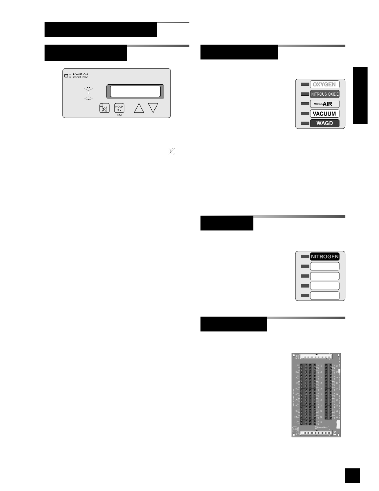
Features:
• User interface pushbuttons for alarm panel
TEST function, audible alarm MUTE
and set-up increase ! and decrease ".
• Green alarm panel POWER ON indicator.
• Red flashing alarm system fault indicator.
• Red audible alarm mute indicator.
• Audible alarm
• General fault relay that activates on any
alarm panel fault condition.
• Auxiliary relay that activates when the
audible alarm is sounding.
• Alphanumeric two line by 20 character
display (Master/Combo Alarms only).
• Embedded web server with web pages to
view and set up alarm.
• 10Base-T Ethernet Jack.
• Ethernet LINK, TX and RX indicators.
• Heartbeat indicator.
• Event log.
(Master/Combo Alarms only)
Features:
• Monitors up to 64 normally
closed dry-contact switch
signals.
• Five gas service indicators
for normal (green) or abnormal (red)
conditions.
• Signal inputs can be programmed to any of
the gas service indicators.
• Adjustable brightness of LED indicators.
• Heartbeat indicator.
(Master/Combo Alarms only)
Features:
• Adds an additional five
gas service indicators to a
Multiplexer Module.
(Master/Combo Alarms only)
Features:
• Screw terminals for 32
dry-contact switch
signals.
• Terminals accept 14 to
22 AWG wires.
• Connector for optional
relay board.
Introduction
Breakout Board
LED Module
Multiplexer Module
Annunciator Module
Alarm Modular Components
Page 8
6
6-847718-00 Rev. B00
Introduction
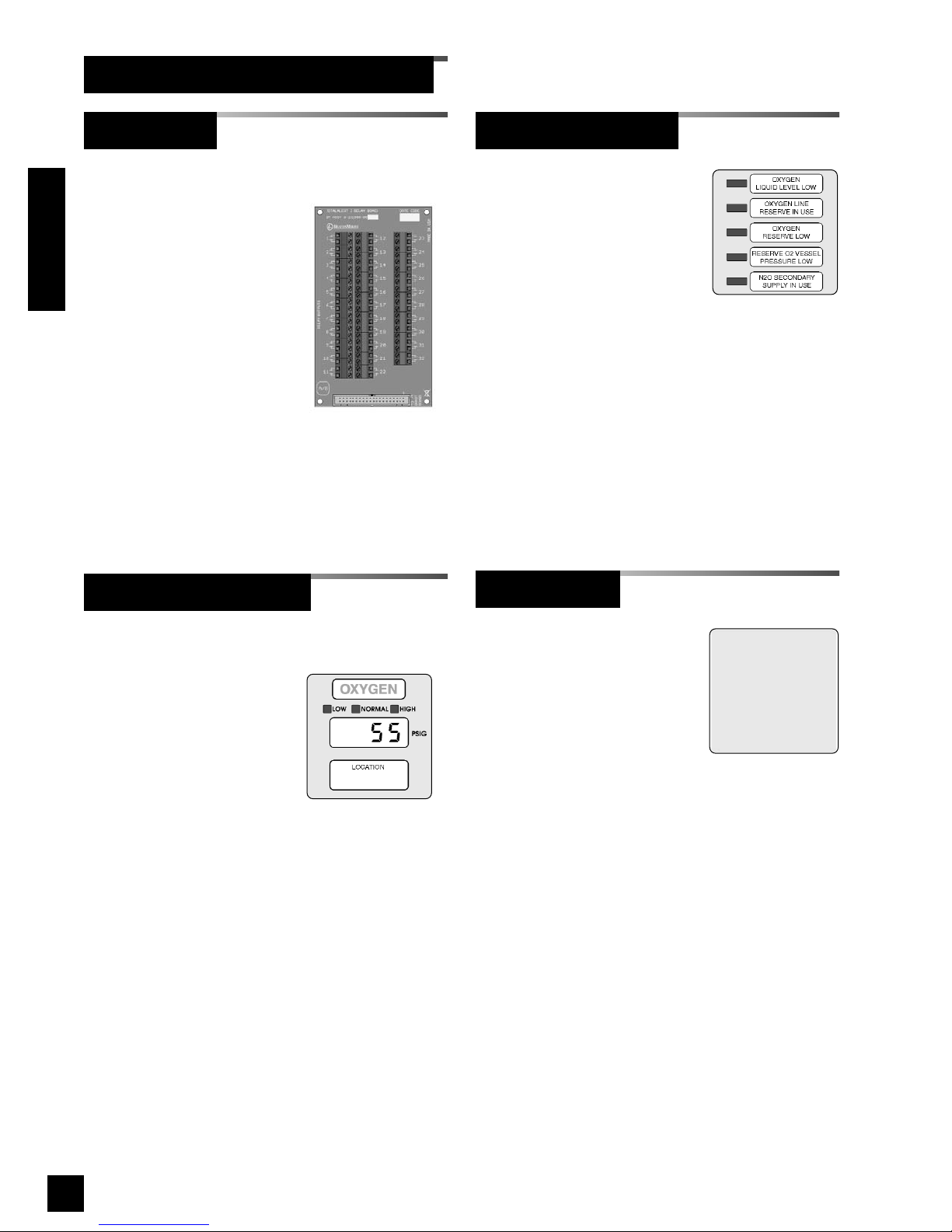
(Area/Combo Alarms only)
Features:
• Digital LED readout of
system pressure signal
transmitted from sensor
module.
• Adjustable brightness of
digital LED readout.
• Individual LED’s indicate when system
pressure/vacuum is HIGH (red), LOW
(red), or NORMAL (green).
• Programmable high and low alarm
thresholds.
• Adjustable audible alarm mute duration.
• Individual high and low alarm dry-contact
relay outputs.
• Can transmit pressure or vacuum signal to
another digital display module for remote
applications.
(Area Alarms only)
Features:
• Monitors up to five
normally closed drycontact switch signals.
• Separate indicators for each of five signals
for normal (green) or abnormal (red)
conditions.
• Available (optional) with separate drycontact relay outputs for each of five
signals.
• Adjustable brightness of LED indicators.
Features:
• Reserves a space in
alarm panel for future
expansion.
• Used to fill unused alarm
panel module locations.
Alarm Modular Components (Cont.)
Blank Module
Multi-Signal Module
Digital Display Module
(Master/Combo Alarms only)
Features:
• Screw terminals for 32
dry-contact relay
outputs. Dry contacts
are normally-closed
when alarm panel is
powered.
• Relay contact ratings
are 2 A @ 30 VDC/0.5 A
@ 125 VAC
.
• Terminals accept 14 to
22 AWG wires.
Relay Board
Page 9

7
6-847718-00 Rev. B00
Address Resolution Protocol (ARP)
Protocol used by a device to learn the MAC
address of another device so it can send it an
Ethernet packet.
Area Alarm Panel
Alarm panel that monitors medical gas and
vacuum systems serving a specific area.
Auxiliary Fault Relay
Single-pole double-throw dry-contact relay
output located on annunciator module. Used
to activate a remote alarm or building
management system. The relay will activate
whenever ANY audible alarm on panel is in
progress. Pressing MUTE button on
annunciator module deactivates relay until
audible alarm is again reactivated.
Combo Alarm Panel
Alarm panel that combines features of a
master alarm panel and an area alarm panel.
Crossover Cable
Network cable that swaps transmit and receive
pairs so cable can be used to connect two
computers or devices without the use of a hub
or switch.
Domain Name Server (DNS)
A device that has a list of device names
matched to IP addresses. Browsers use this
resource to locate the IP address of a named
device. NetBIOS name service provides this
function on a local network.
Dry-Contact
Electrical contact isolated or unconnected from
any electrical source.
Dynamic Host Configuration Protocol
(DHCP)
A protocol used by a server to assign IP
addresses to devices and computers.
Definitions
Definition of Statements
Statements in this manual preceded by following
words are of special significance.
WARNING: Means there is a possibility
of injury or death to yourself or others.
CAUTION: Means there is a possibility
of damage to unit or other property.
SHOCK HAZARD: Means there is a
possibility of electric shock.
NOTE:
Indicates points of particular interest
for more efficient and convenient operation.
ATTENTION: Means precautions for
handling electrostatic sensitive devices are
to be observed.
Introduction
Page 10

8
6-847718-00 Rev. B00
Introduction
Electromagnetic Compatibility (EMC)
Verification that a product meets required
standards for emmisions of and immunity from
electromagnetic energy in its intended
environment.
Ethernet
A standard high-speed network medium
specified by IEEE standard 802.3.
Ethernet Hub
A device that connects many Ethernet devices
together. All devices on the hub receive
messages sent from all of the other connected
devices.
Ethernet Switch
A device that connects many Ethernet devices
together with optimization. Message
destinations are examined and passed only to
the correct device.
Firewall
A computer or computer software that prevents
unauthorized access to private data from
outside computer users.
Gateway
A computer or device that connects two
computer networks together (such as a private
network and the Internet).
General Fault Relay
Single-pole double-throw dry-contact relay
output located on annunciator module. Used to
activate remote alarm or building management
system. Relay will activate whenever ANY
audible alarm on panel is in progress. Unlike
Auxiliary Fault Relay, pressing MUTE button
on annunciator module WILL NOT deactivate
relay. General Fault Relay will deactivate only
after alarm condition is corrected and alarm
panel resumes normal status.
HyperText Transfer Protocol (HTTP)
Protocol used to manage the request and
transfer of web pages to a computer.
Internet Protocol (IP) Address
Unique number that identifies a device on a
network.
LED
Light Emitting Diode
Local Sensors
Pressure / vacuum sensors mounted inside
alarm panel back box. Sensor rough-in must
be piped to medical gas / vacuum pipelines.
Media Access Control (MAC) Address
A unique hardware address of a device on an
Ethernet.
Master Alarm Panel
Monitors medical gas and vacuum source
equipment and main pipelines.
NetBIOS Name Service
Local method of addressing a device by name.
This allows a web browser to reference a
device by name, such as TA2_12345, instead of
an IP address, such as 192.168.2.3.
Remote Sensors
Pressure / vacuum sensors mounted outside of
alarm panel back box. Sensor rough-ins may
be mounted separately or ganged together near
pressure / vacuum pipelines. Sensors must
then be wired to alarm panel.
Simple Mail Transfer Protocol (SMTP)
Protocol for sending email on a network.
Subnet Mask
A binary number used to separate the network
portion from the host portion of a network
address.
SMTP Client
Computer or device that uses SMTP to send
email by communicating with an SMTP server.
The TotalAlert 2 acts as an SMTP client.
SMTP Server
Computer or device that uses SMTP to receive
email from an SMTP client and then transfer it
across the internet.
Definitions (Cont.)
Page 11

9
6-847718-00 Rev. B00
Transmission Control Protocol (TCP)
Protocol used to send data streams between
two devices. TCP guarantees reliable and in
order data from sender to receiver.
User Datagram Protocol (UDP)
Protocol used to send short messages between
computers. UDP does not guarantee reliable
transmission (packets may be lost, duplicated or
out of order), but is faster and more efficient
than TCP.
VFD
Vacuum Fluorescent Display
Definitions (Cont.)
Introduction
Page 12

10
6-847718-00 Rev. B00
Alarm Configurations
Introduction
All TotalAlert 2 alarm panels are factory preconfigured. Configuration of alarm panel varies
dependent upon customer’s requirements.
Three types of alarm panels are available.
• Master alarms (6-TA2M series) (Page 11)
• Area alarms (6-TA2A series) (Page 12)
• Combo alarms (6-TA2C series) (Page 14)
Page 13
11
6-847718-00 Rev. B00
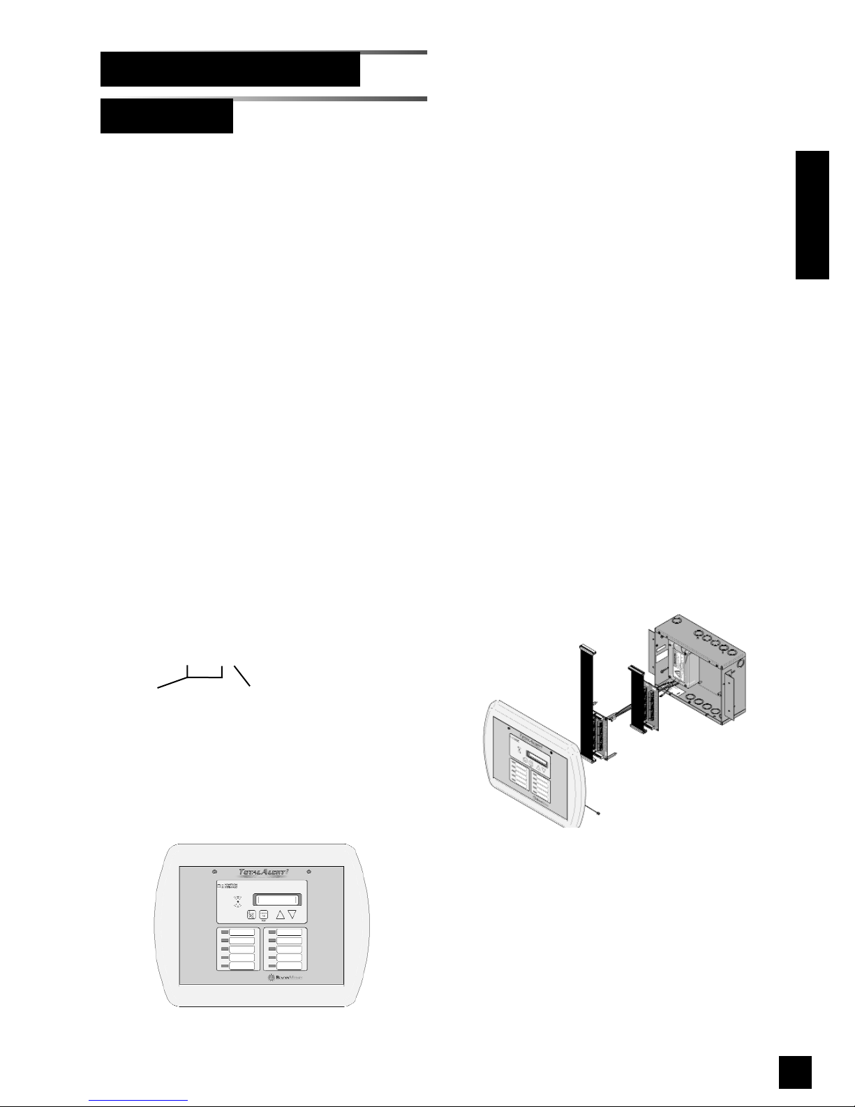
Model Number Scheme:
6-TA2M _ _ _
32 or 64
Designates number
of signals
R or blank
R = With Relays
Master alarm panels include the following
modular components:
• Annunciator module with VFD
• One multiplexer module
• One LED module
• One or two breakout boards
• One or two relay boards (Optional)
Master alarm panels can monitor 32 or 64
switched inputs.
Inputs can be assigned to any one of 10
gas service indicators.
2 line by 20 character vacuum fluorescent
display shows signal names.
Optional dry contact relays are available
for all signals.
Master Alarms
Alarm Configurations (Cont.)
Example: P/N 6-TA2M32R
Introduction
Figure 4: Master Alarm
Figure 3: Master Alarm Panel
Page 14
12
6-847718-00 Rev. B00
Introduction
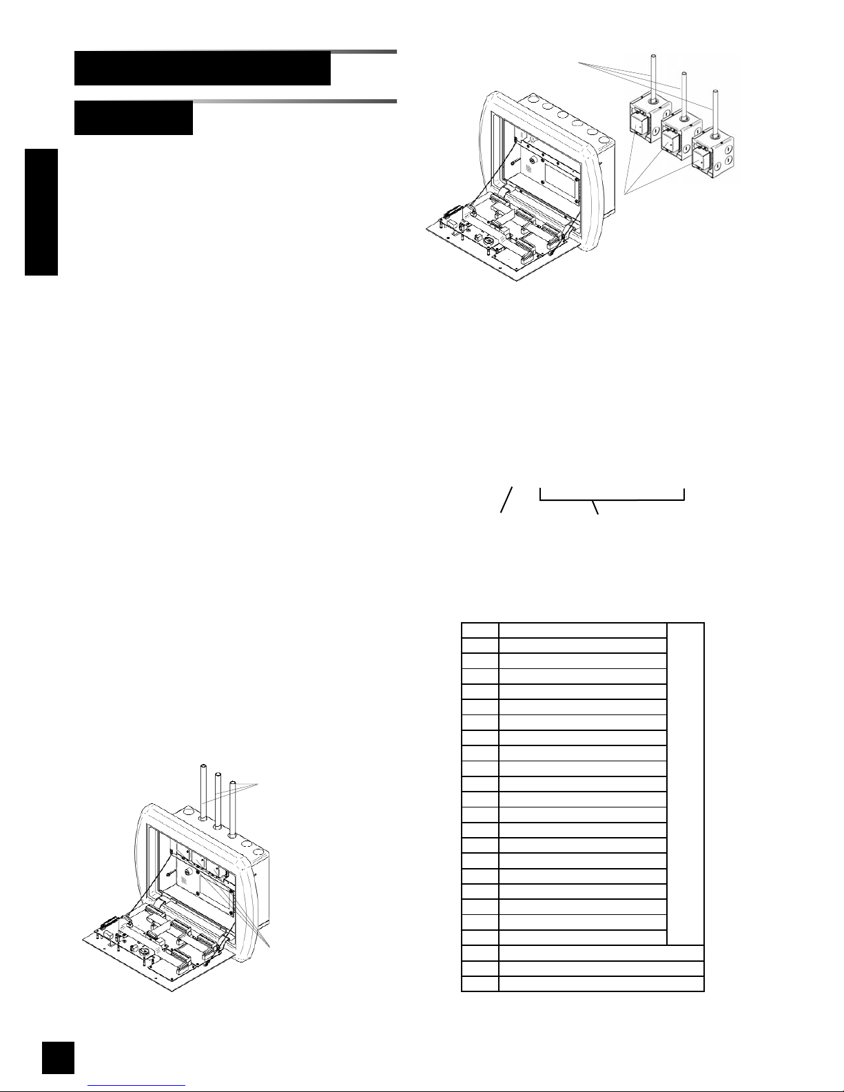
Sensor modules are
mounted inside alarm
panel box
Copper tubes connect to
pressure/vacuum
pipelines
Area alarm panels include the following modular
components:
• Annunciator module
• 4 or 8 digital display, multi-signal or blank
modules
• Sensors for all digital display modules
(except 6-TA2AN series)
Area alarm panels may consist of any
combination of digital display modules, multisignal modules or blank modules.
If alarm panel is configured with digital display
modules, pressure/vacuum sensors will be
included for connection to pressure / vacuum
pipeline (except 6-TA2AN series).
Sensors may be located inside alarm panel
back box (local sensors) or outside alarm panel
back box (remote sensors).
Local sensors must be connected to pressure /
vacuum pipelines via copper tubing (Figure 5).
Remote sensor may be mounted near pressure
/ vacuum pipeline and then wired to alarm panel
(Figure 6).
Two alarm panel sizes support either 4 or 8
alarm modules.
Area Alarms
O
OXYGEN
D
OXYGEN - 100 PSI
X
NITROUS OXIDE
A
MEDICAL AIR
F
MEDICAL AIR - 100 PSI
5
AIR (ISO)
7
LABORATORY AIR
2
O2-CO2
4
O2-He
C
CARBON DIOXIDE
G
CARBON DIOXIDE - 100 PSI
1
CO2-O2
3
He-O2
H
HELIUM
V
VACUUM
6
VACUUM (ISO)
8
LABORATORY VAC
W
WAGD
N
NITROGEN
9
INSTRUMENT AIR
J
ARGON
DIGITAL DISPLAY MODULES
M
MULTI-SIGNAL MODULE
R
MULTI-SIGNAL MODULE W/ RELAYS
B
BLANK
Alarm Configurations (Cont.)
Model Number Scheme:
12345678
6-TA2A _ - _ _ _ _ _ _ _ _
L = Local Sensors
R = Remote Sensors
N = No Sensors
Position within alarm panel
(Figures 7 and 8)
Designates type of alarm
panel component from table
Figure 5: Local Sensors
Figure 6: Remote Sensors
Sensors have separate
mounting boxes for
mounting near
pressure/vacuum
pipeline and then must
be wired to alarm panel
Copper tubes connect to
pressure/vacuum pipelines
Page 15
13
6-847718-00 Rev. B00
NOTE:
When an alarm panel is ordered with either local
or remote sensors, ALL sensors will either be
local or remote. Alarm panels with combination of
local and remote sensors are not available.
NOTE:
Alarm panel components in table on previous
page are listed in order of criticality. Unless otherwise specified, most critical component will fill
position one, next less critical component will fill
position two, etc. etc.
234
1
123
45678
Area Alarms (Cont.)
Alarm Configurations (Cont.)
Introduction
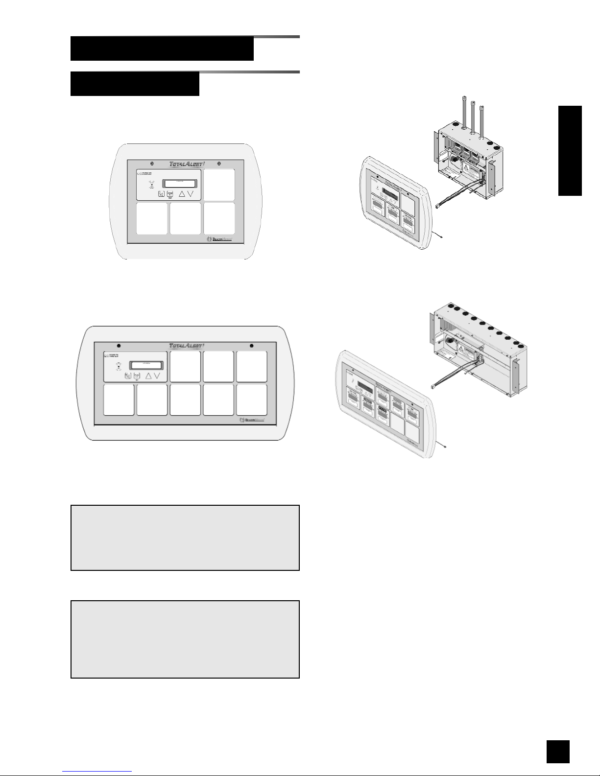
Example: Model Number 6-TA2AR-OXAVWNBB
Example: Model Number 6-TA2AL-BOAV
Figure 10: Large Area Alarm
Figure 9: Small Area Alarm Panel
Figure 8: Large Area Alarm Front Panel
Figure 7: Small Area Alarm Front Panel
Page 16
14
6-847718-00 Rev. B00
123
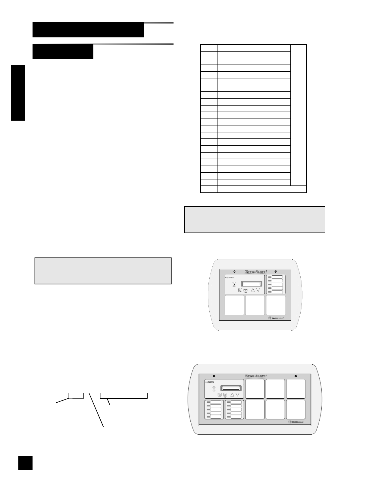
Figure 12: Large Combo Alarm Front Panel
123
456
Model Number Scheme:
123456
6-TA2C _ _ _ - _ _ _ _ _ _
Position within alarm panel
(Figures 11 and 12)
Designates type of alarm
panel component from table
Alarm Configurations (Cont.)
Combo Alarms
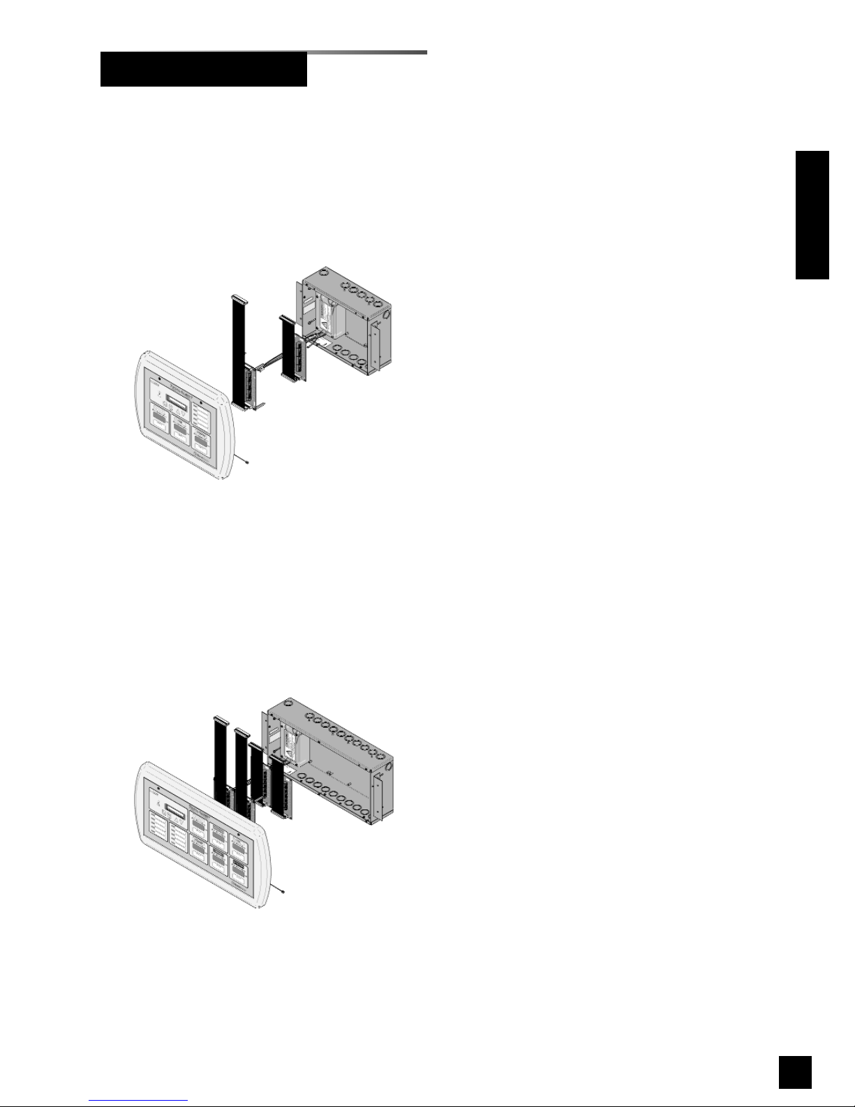
Combo alarms include the following modular
components:
• Annunciator module with VFD
• One multiplexer module
• One LED module (Large Combo Only).
• One or two breakout boards
• One or two relay boards (Optional)
• 3 or 6 digital display or blank modules
Combo alarms can monitor 32 or 64
switched inputs.
Inputs can be assigned to any one of 5
(small combo) or 10 (large combo) gas
service indicators.
Optional dry contact relays are available
for all signals.
Combo alarms can also monitor up to 3
(small combo) or 6 (large combo) digital
display modules.
NOTE:
Sensors on combo alarms are always remotely
mounted.
32 or 64
Designates number
of signals
R or blank
R = With Relays
O
OXYGEN
D
OXYGEN - 100 PSI
X
NITROUS OXIDE
A
MEDICAL AIR
F
MEDICAL AIR - 100 PSI
5
AIR (ISO)
7
LABORATORY AIR
2
O2-CO2
4
O2-He
C
CARBON DIOXIDE
G
CARBON DIOXIDE - 100 PSI
1
CO2-O2
3
He-O2
H
HELIUM
V
VACUUM
6
VACUUM (ISO)
8
LABORATORY VAC
W
WAGD
N
NITROGEN
9
INSTRUMENT AIR
J
ARGON
DIGITAL DISPLAY MODULES
B
BLANK
NOTE:
Multi-signal modules are not allowed in
combination alarms.
Introduction
Figure 11: Small Combo Alarm Front Panel
Page 17
15
6-847718-00 Rev. B00
Example: Model Number 6-TA2C64-OXAVWN
Example: Model Number 6-TA2C32R-OAV
Combo Alarms (Cont.)
Introduction
Figure 14: Large Combo Alarm Panel
Figure 13: Small Combo Alarm Panel
Page 18

16
6-847718-00 Rev. B00
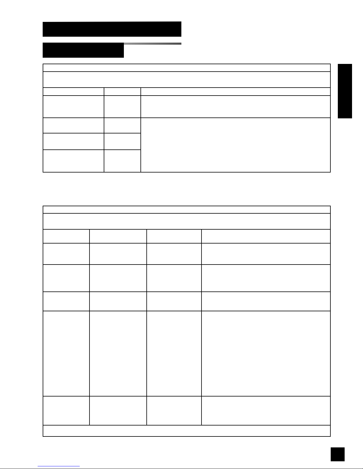
This device complies with part 15 of the
FCC Rules. Operation is subject to the following two conditions: (1) This device may
not cause harmful interference, and (2) this
device must accept any interference
received, including interference that may
cause undesired operation.
This Class A digital apparatus complies
with Canadian ICES-003.
Cet appareil numérique de la classe A est
conforme à la norme NMB-003 du Canada.
Medical Electrical Equipment needs special precautions regarding EMC and needs
to be installed and put into service according to the EMC information provided in this
manual.
Portable and mobile RF communications
equipment can affect Medical Electrical
Equipment.
The use of accessories, transducers, and
cables other than those specified by the
manufacturer, may result in increased
emissions or decreased immunity of the
TotalAlert 2.
The TotalAlert 2 should not be used adjacent to, or stacked with, other equipment. If
adjacent or stacked use is necessary, the
TotalAlert 2 should be observed to verify
normal operation in the configuration in
which it will be used.
EN 60601-1-2
ICES-003
FCC
Electromagnetic Compatibility
Introduction
Page 19
17
6-847718-00 Rev. B00
Electromagnetic Compatibility (Cont.)
Introduction
EN 60601-1-2 (Cont.)
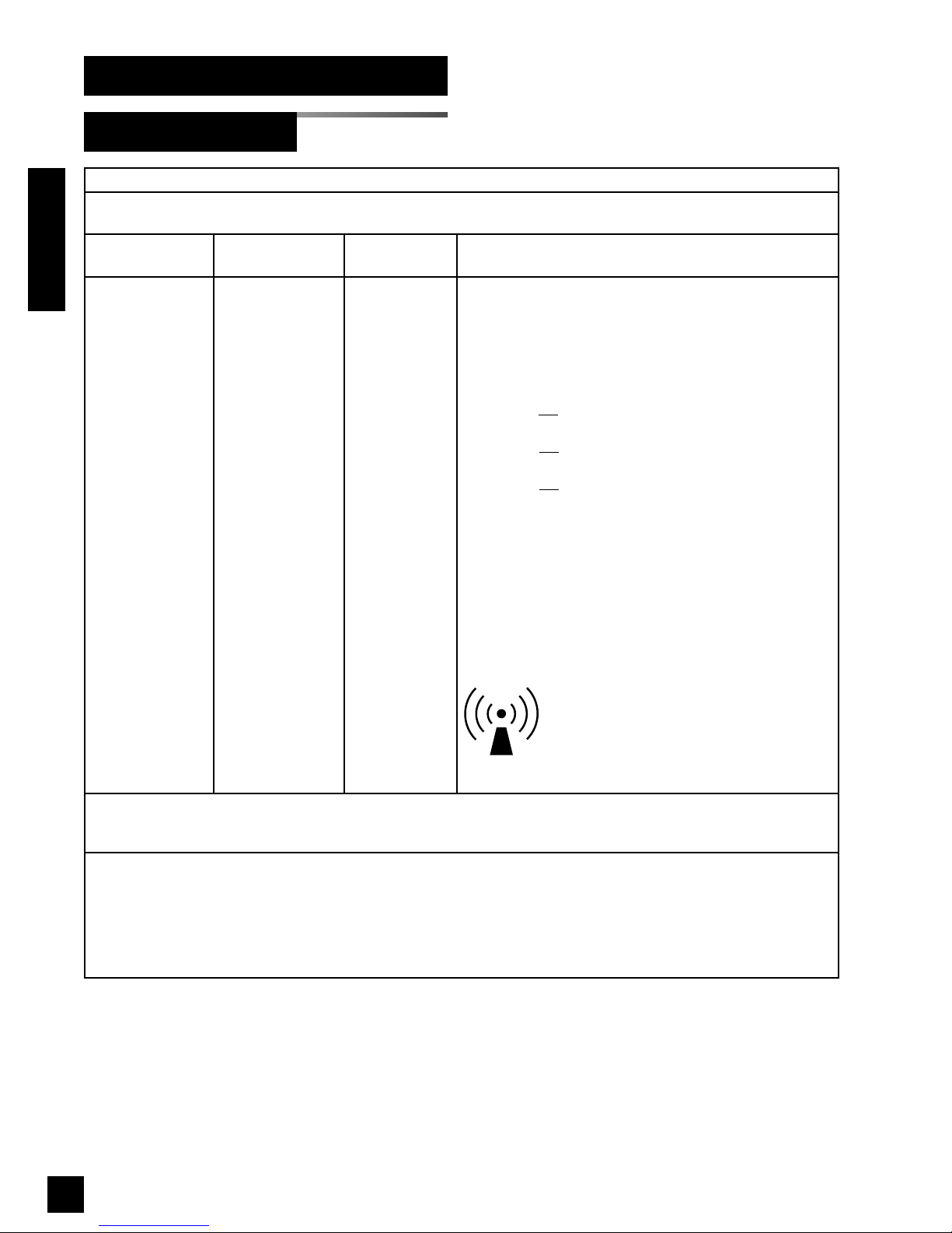
Guidance and manufacturer's declaration - electromagnetic emissions
The TotalAlert 2 is intended for use in the electromagnetic environment specified below. The customer or the user of the TotalAlert 2
should assure that it is used in such an environment.
Emissions test Compliance Electromagnetic environment - guidance
RF emissions
CISPR 11
Group 1
The TotalAlert 2 uses RF energy only for its internal function. Therefore, its RF
emissions are very low and are not likely to cause any interference in nearby electronic
equipment.
RF emissions
CISPR 11
Class A
The TotalAlert 2 is suitable for use in all establishments other than domestic and those
directly connected to the public low-voltage power supply network that supplies
buildings used for domestic purposes.
Harmonic emissions
IEC 61000-3-2
Class A
Voltage fluctuations/
Flicker emissions
IEC 61000-3-3
Complies
Guidance and manufacturer's declaration - electromagnetic immunity
The TotalAlert 2 is intended for use in the electromagnetic environment specified below. The customer or the user of the TotalAlert 2
should assure that it is used in such an environment.
Immunity test
IEC 60601
test level
Compliance level Electromagnetic environment - guidance
Electrostatic
Discharge (ESD)
IEC 61000-4-2
±6 kV contact
±8 kV air
±6 kV contact
±8 kV air
Floors should be wood, concrete or ceramic tile. If floors
are covered with synthetic material, the relative humidity
should be at least 30 %.
Electrical fast
transient/burst
IEC 61000-4-4
±2 kV for power supply
lines
±1 kV for input/output
lines
±2 kV for power supply
lines
±1 kV for input/output
lines
Mains power quality should be that of a typical
commercial or hospital environment.
Surge
IEC 61000-4-5
±1 kV differential mode
±2 kV common mode
±1 kV differential mode
±2 kV common mode
Mains power quality should be that of a typical
commercial or hospital environment.
Voltage dips, short
Interruptions and
voltage variations
on power supply
input lines
IEC 61000-4-11
<5 % U
T
(>95 % dip in UT)
for 0,5 cycle
<40 %
U
T
(>60 % dip in UT)
for 5 cycles
<70 %
U
T
(>30 % dip in UT)
for 25 cycles
<5 %
U
T
(>95 % dip in UT)
for 5 sec
<5 % U
T
(>95 % dip in UT)
for 0,5 cycle
<40 %
U
T
(>60 % dip in UT)
for 5 cycles
<70 %
U
T
(>30 % dip in UT)
for 25 cycles
<5 %
U
T
(>95 % dip in UT)
for 5 sec
Mains power quality should be that of a typical
commercial or hospital environment. If the user of the
TotalAlert 2 requires continued operation during power
mains interruptions, it is recommended that the
TotalAlert 2 be powered from an uninterruptible power
supply or battery.
Power frequency
(50/60 Hz) magnetic field
IEC 61000-4-8
3 A/m 3 A/m Power frequency magnetic fields should be at levels
characteristic of a typical location in a typical commercial
or hospital environment.
NOTE UTis the a.c. mains voltage prior to application of the test level.
Page 20
18
6-847718-00 Rev. B00
Introduction
Electromagnetic Compatibility (Cont.)
EN 60601-1-2 (Cont.)
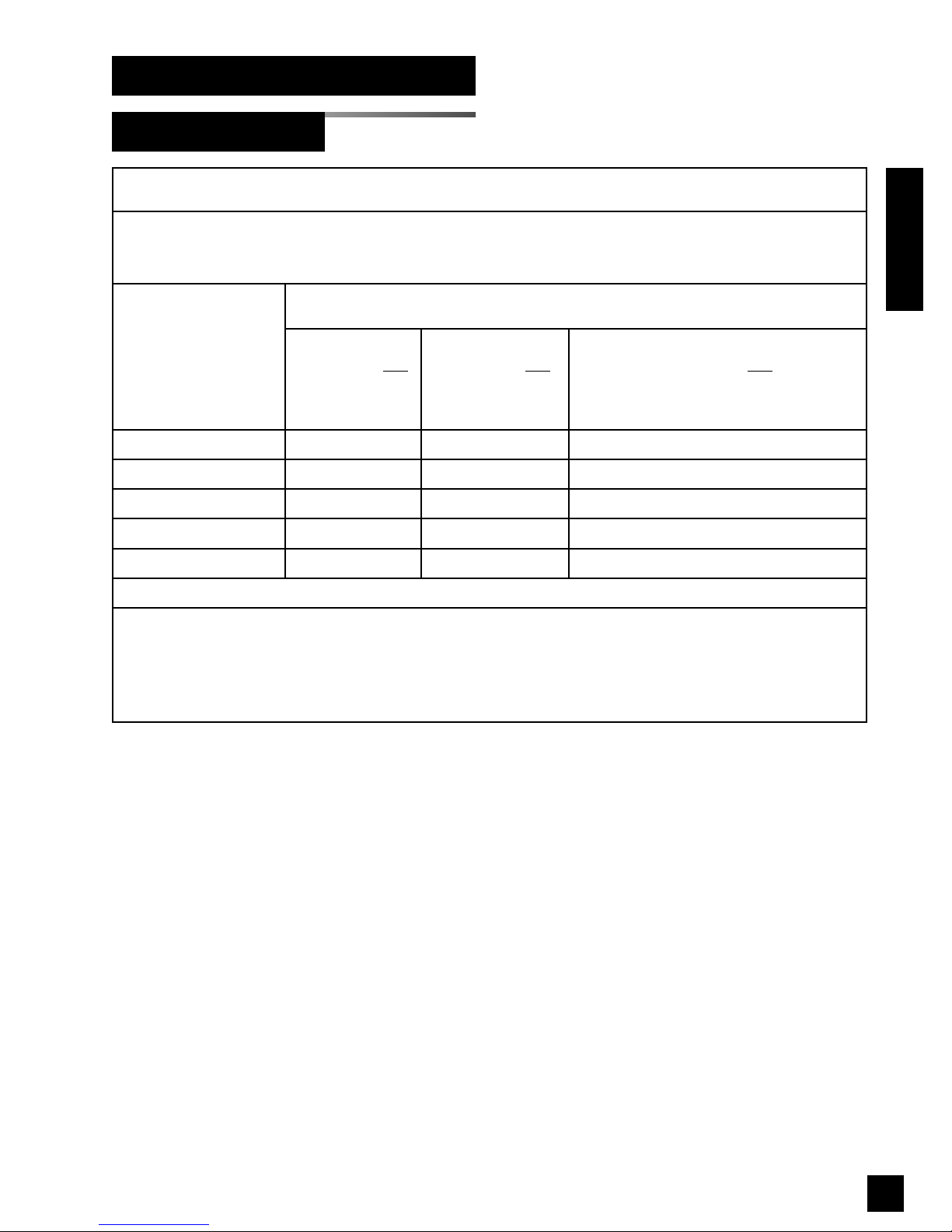
Guidance and manufacturer's declaration - electromagnetic immunity
The TotalAlert 2 is intended for use in the electromagnetic environment specified below. The customer or the user of the TotalAlert 2
should assure that it is used in such an environment.
Immunity test
IEC 60601
test level
Compliance level Electromagnetic environment - guidance
Conducted RF
IEC 61000-4-6
Radiated RF
IEC 61000-4-3
3 Vrms
150 kHz to 80 MHz
3 V/m
80 MHz to 2,5 GHz
3 Vrms
3 V/m
Portable and mobile RF communications equipment should be
used no closer to any part of the TotalAlert 2, including cables,
than the recommended separation distance calculated from the
equation applicable to the frequency of the transmitter.
Recommended separation distance
d = 1,2√P
d = 1,2√P
80 MHz to 800 MHz
d = 2,3√P 800 MHz to 2,5 GHz
where P is the maximum output power rating of the transmitter in
watts (W) according to the transmitter manufacturer and d is the
recommended separation distance in metres (m).
Field strengths from fixed RF transmitters, as determined by an
electromagnetic site survey,
a
should be less than the compliance
level in each frequency range.
b
Interference may occur in the vicinity of equipment marked with
the following symbol:
NOTE 1 At 80 MHz and 800 MHz, the higher frequency range applies.
NOTE 2 These guidelines may not apply in all situations. Electromagnetic propagation is affected by absorption and reflection from
structures, objects and people.
a
Field strengths from fixed transmitters, such as base stations for radio (cellular/cordless) telephones and land mobile radios,
amateur radio, AM and FM radio broadcast and TV broadcast cannot be predicted theoretically with accuracy. To assess the
electromagnetic environment due to fixed RF transmitters, and electromagnetic site survey should be considered. If the
measured field strength in the location in which the TotalAlert 2 is used exceeds the applicable RF compliance level above, the
TotalAlert 2 should be observed to verify normal operation. If abnormal performance is observed, additional measures may be
necessary, such as reorienting or relocating the TotalAlert 2.
b
Over the frequency range 150 kHz to 80 MHz, field strengths should be less than 3 V/m.
Page 21
19
6-847718-00 Rev. B00
Electromagnetic Compatibility (Cont.)
EN 60601-1-2 (Cont.)
Introduction
Recommended separation distances between
portable and mobile RF communications equipment and the TotalAlert 2
The TotalAlert 2 is intended for use in the electromagnetic environment in which radiated RF disturbances are controlled. The
customer or the user of the TotalAlert 2 can help prevent electromagnetic interference by maintaining a minimum distance between
portable and mobile RF communications equipment (transmitters) and the TotalAlert 2 as recommended below, according to the
maximum output power of the communications equipment.
Rated maximum output
power of transmitter
W
Separation distance according to frequency of transmitter
m
150 kHz to 80 MHz
d = 1,2√P
80 MHz to 800 MHz
d = 1,2√P
800 MHz to 2,5 GHz
d = 2,3√P
0,01 0,12 0,12 0,23
0,1 0,38 0,38 0,73
1 1,2 1,2 2,3
10 3,8 3,8 7,3
100 12 12 23
For transmitters rated at a maximum output power not listed above, the recommended separation distance d in metres (m) can be
estimated using the equation applicable to the frequency of the transmitter, where P is the maximum output power rating of the
transmitter in watts (W) according to the transmitter manufacturer.
NOTE 1 At 80 MHz and 800 MHz, the separation distance for the higher frequency range applies.
NOTE 2 These guidelines may not apply in all situations. Electromagnetic propagation is affected by absorption and reflection from
structures, objects and people.
Page 22

20
6-847718-00 Rev. B00
Page 23

21
6-847718-00 Rev. B00
1. Install alarm panel back box (Page 23).
2. Pull wire (Page 27).
3. Power supply wiring (Page 30).
4. Breakout board input wiring (Page 32).
5. Relay board wiring (Page 33).
6. Front panel installation (Page 40).
7. Ethernet wiring (Page 37).
8. General fault/Aux Relay wiring (if
required) (Page 36).
9. Building automation system wiring (if
required) (Page 37).
10.Labeling (Page 43).
1. Install alarm panel back box (Page 23).
2. Install remote sensor back box (if
required) (Page 24).
3. Pipeline connections (Page 25).
4. Pull wire (Page 27).
5. Power supply wiring (Page 30).
6. Front panel installation (Page 40).
7. Remote sensor wiring (if required)
(Page 31).
8. Sensor installation (Local: Page 41,
Remote: Page 42).
9. Ethernet wiring (Page 37).
10.Digital display module master/slave
wiring (if required) (Page 35).
11. Digital display module high/low relay
wiring (if required) (Page 36).
12.Multi-signal module input wiring (if
required) (Page 34).
13. Multi-signal module relay output wiring
(if required) (Page 35).
14.General fault/Aux Relay wiring (if
required) (Page 36).
15.Labeling (Page 43).
Area Alarms
Master Alarms
Installation Overview
Page 24

22
6-847718-00 Rev. B00
Combo Alarms
Installation Overview
1. Install alarm panel back box (Page 23).
2. Install remote sensor back box
(Page 24).
3. Pipeline connections (Page 25).
4. Pull wire (Page 27).
5. Power supply wiring (Page 30).
6. Breakout board input wiring (Page 32).
7. Relay board wiring (Page 33).
8. Front panel installation (Page 40).
9. Remote sensor wiring (if required)
(Page 31).
10.Remote sensor installation (Page 42).
11. Ethernet wiring (Page 37).
12.Digital display module master/slave
wiring (if required) (Page 35).
13.Digital display module high/low relay
wiring (if required) (Page 36).
14.General fault/Aux Relay wiring (if
required) (Page 36).
15.Building automation system wiring (if
required). (Page 37)
16.Labeling (Page 43).
Page 25
23
6-847718-00 Rev. B00
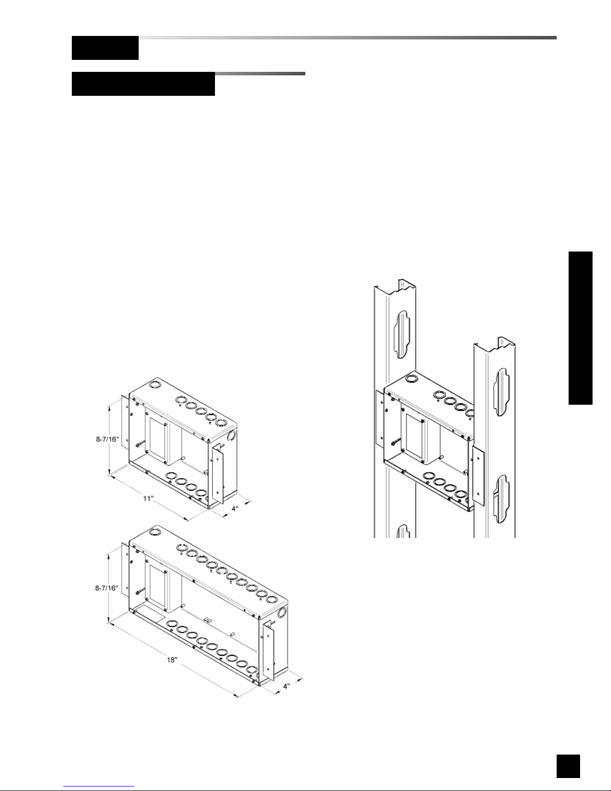
Alarm panel back box will be one of two
sizes. Height and depth of both size
boxes are identical. Refer to Figure 15
for dimensions of both boxes.
If alarm panel is configured with digital
display modules, sensor assemblies will
be included for connection to pressure /
vacuum pipeline.
Sensors may be located inside alarm
panel back box (local sensors) or outside
alarm panel back box (remote sensors).
If equipped with local sensors, copper
tubes will extend from top of back box to
be connected to pressure / vacuum
pipeline.
Alarm Panel Back Box
1. Prepare rough wall opening large
enough to accommodate alarm panel
back box. Alarm panel back box must
have rigid vertical members for
support on both left and right sides.
Power to alarm panel shall enter
through lower left or top left conduit
hole in back box.
2. Remove cardboard dust cover and
insert alarm panel back box into wall
opening. Secure with fasteners
suitable for vertical supports
(Figure 16).
3. Mounting brackets on each side of
back box are adjustable and factory
preset for 5/8” thick drywall. After
drywall installation, front edge of back
box should be flush with finished
surface of wall. If needed, make any
necessary bracket adjustments at this
time (Figure 17).
4. Reinstall cardboard dust cover.
Figure 16: Back Box Mounting
Small box
Large box
Back Box details
simplified for clarity
Rough-In
Installation Procedures
Figure 15: Alarm Panel Back Box Dimensions
Page 26
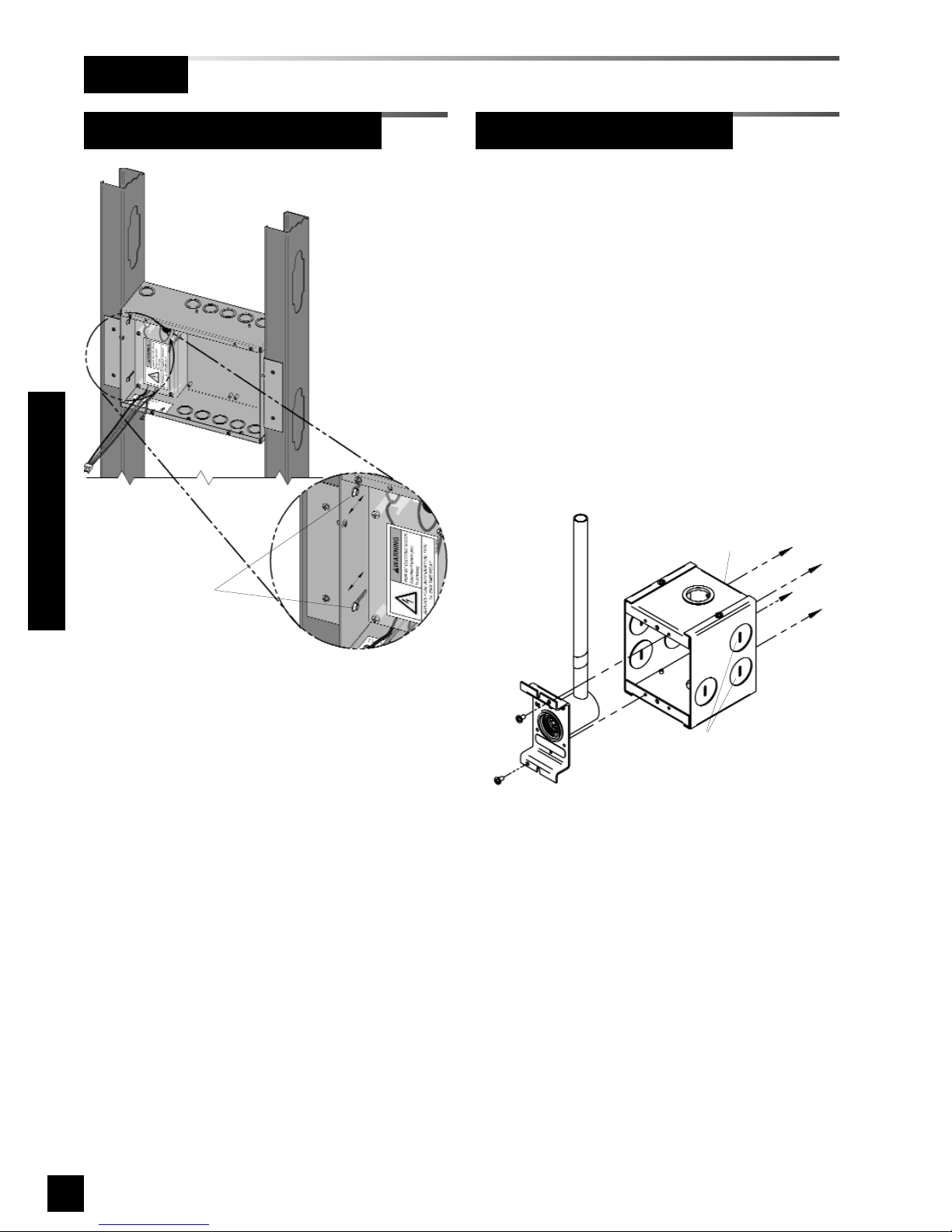
Alarm panels ordered with remote
sensors are provided with separate metal
boxes for each sensor. Mount each
sensor box as follows:
1. Remove sensor rough-in from
mounting box (Figure 18).
2. Using four mounting holes provided,
attach box to a wall or other structural
support (fasteners by others).
3. Reinstall sensor rough-in.
24
6-847718-00 Rev. B00
Rough-In
Figure 18: Remote Sensor Back Box
Loosen screws to
adjust back box depth
(same each side)
Four holes in back of box are
provided for surface mounting
Rear conduit knockouts
(either side) are recommended
for sensor wiring
Remote Sensor Back Box
Alarm Panel Back Box (Cont.)
Installation Procedures
Figure 17: Mounting Bracket Adjustment
Page 27
25
6-847718-00 Rev. B00
Pipeline Connection
Sensor Module
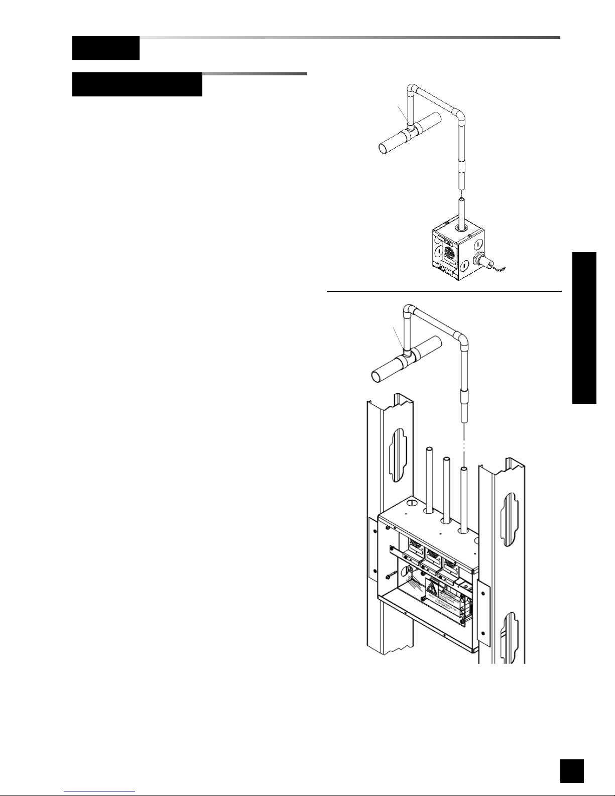
1. Braze copper extension tubes from
sensor rough-in to appropriate
pressure/vacuum piping system drops
(Figure 19). Braze connections per
procedures required by NFPA 99 or
CAN/CSA-Z305.1. Use appropriate
measures to prevent overheating and
damage to internal components of
sensor rough-in assemblies.
2. Perform standing pressure tests and
cross connection tests as required by
NFPA and CSA.
Installation Procedures
Rough-In
Figure 19: Sensor Pipeline Connection
Connection
should be made
on top of pipe
Horizontal run of pipeline
Horizontal run of pipeline
Connection
should be made
on top of pipe
REMOTE SENSOR
LOCAL SENSOR
Page 28
26
6-847718-00 Rev. B00
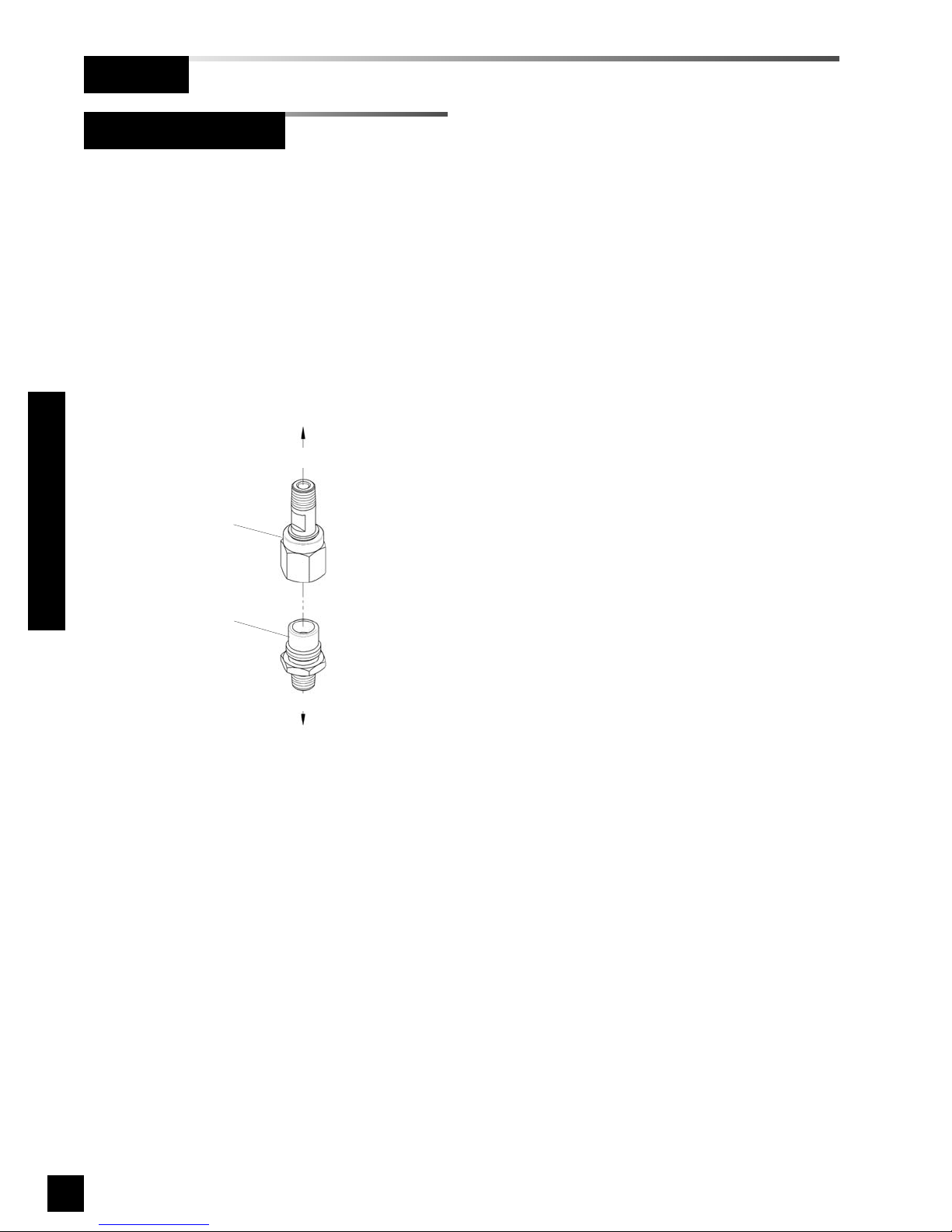
Pressure Switch
DISS (Diameter Index Safety System)
connection kits are recommended for use
when attaching pressure switches to
pressure/vacuum pipeline. To utilize these
kits, a 1/4-18 NPT female thread must be
provided in piping system. All necessary
components are included in each gas
specific kit (Figure 20).
Rough-In
Pipeline Connection
Figure 20: Pressure Switch Pipeline Connection
DISS Kit Gas Service
Model No:
6-120004-10 Oxygen
6-120004-11 Nitrous Oxide
6-120004-12 Medical Air
6-120004-13 Vacuum
6-120004-14 Nitrogen
6-120004-18 Instrument Air
6-120004-19 Evac. (WAGD)
6-120004-20 Carbon Dioxide
6-120004-21 CO2/O2
6-120004-22 O2/CO2
6-120004-23 He/O2
6-120004-24 O2/He
6-120004-25 Helium
To pipeline
To pressure switch
DISS male
body
with check
DISS nut
and nipple
Installation Procedures
Page 29

27
6-847718-00 Rev. B00
• Power all alarms from life safety
branch of emergency power system as
required by applicable standards.
• Protect all wiring from physical
damage by raceways or conduit as
required by applicable standards.
• Wire master panels directly to
switches or sensors as required by
applicable standards.
• Wiring runs should be made with color
coded wire. Record color, signal, and
source of signal for each wiring lead to
aid in connection of alarm finish
components.
• Avoid installing alarm panels near
radio transmitters, electrical motors, or
switchgear.
All low voltage wiring must meet the following criteria:
• Copper wire no smaller than 22 AWG.
• Circuit length not to exceed 5000 feet.
• Cable must be twisted-pair shielded
type. Multi-pair cables within one
common shield are acceptable.
Wire Type And SizeGeneral Requirements
Pull Wire
Installation Procedures
Page 30
28
6-847718-00 Rev. B00
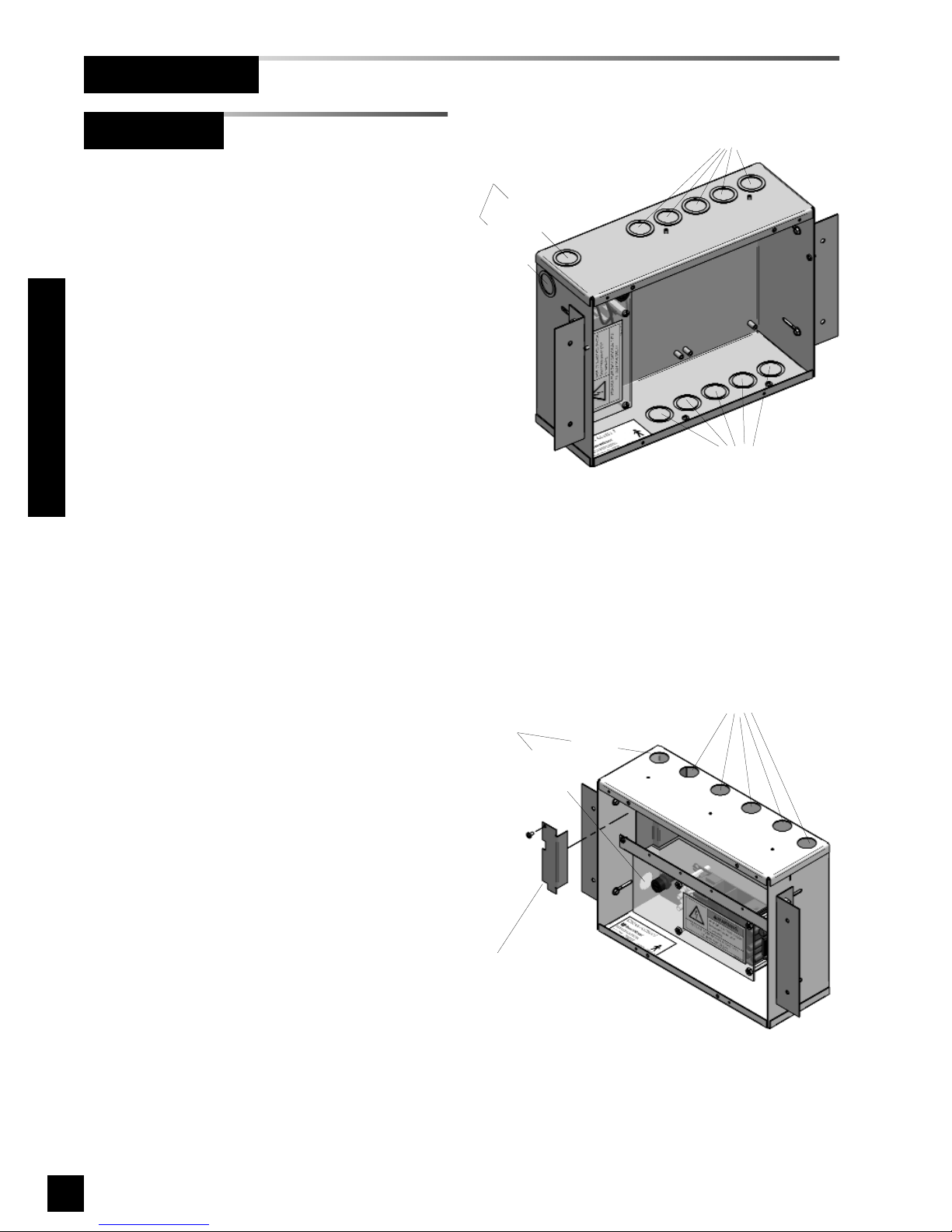
Holes for entrance of
low voltage field wiring
Two choices of
conduit holes for
entrance of AC
mains power
to
p
e
n
try
side entry
For top entry, remove
shield for access.
Reinstall shield after
connection is made
Figure 22: Wire Routing for Area Alarms
Figure 21: Wire Routing for Master / Combo Alarms
Two holes or knockouts are provided for
entrance of AC mains power. One hole
on left side and one hole on top left of
alarm panel back box.
NO OTHER HOLES SHOULD BE
PUNCHED OR USED.
Several additional holes or knockouts are
provided on right side of top panel and
bottom for entrance of low voltage field
wiring(Figures 21 and 22).
Two choices of
conduit knockouts
for entrance of AC
mains power
top entry
side entry
Knockouts for entrance of
low voltage field wiring
Knockouts for entrance of
low voltage field wiring
Wire Routing
Pull Wire (Cont.)
Installation Procedures
Page 31

29
6-847718-00 Rev. B00
Determining Number Of Conductors
• Relay outputs
Two conductors are required for each
signal between relay output terminals
and remote device (such as a building
automation system).
Refer to Wiring Schematic 4
(Page 49) for multiplexer/relay board.
Refer to Wiring Schematic 7
(Page 52) for multi-signal module.
Refer to Wiring Schematic 8
(Page 53) for annunciator module.
Refer to Wiring Schematic 9
(Page 53) for digital display module.
• Digital display module master/slave
Two panels may be connected
together so digital display module
pressure reading(s) of first panel will
be duplicated at second panel.
Two conductors for each digital display
module must be routed from first
alarm panel to second alarm panel.
Refer to Wiring Schematic 6
(Page 51).
• Ethernet
An eight conductor category 5 network
cable is required between each alarm
panel to be networked and a facility’s
Ethernet hub or switch.
The following rules along with references
to this manual’s schematics clarify wiring
requirements.
• Digital display modules to sensors
Two conductors are required between
each digital display module and
sensor module (twisted pair).
Refer to Wiring Schematic 2
(Page 47).
• Switched signal inputs
Two conductors are required for each
signal between the signal input
terminals and the source signal switch.
These signals can originate at source
equipment or from pressure switches
mounted on main pressure / vacuum
pipelines.
When two master alarms are required,
the same switch / relay contacts can
be wired to both alarm panels.
(See CAUTION below).
Both pairs of wires should originate
from switch/relay contacts.
Refer to Wiring Schematic 3
(Page 48) for multiplexer/breakout
board.
Refer to Wiring Schematic 5
(Page 50) for multi-signal module.
Refer to Wiring Schematic 10
(Page 54) for pressure switches.
Pull Wire (Cont.)
Installation Procedures
CAUTION:
Do not connect TotalAlert 2 master/combo alarm
to switch/relay contacts connected to any alarm
panels other than those listed below:
• TotalAlert 2
• MEGA2
• MEGA
Page 32
30
6-847718-00 Rev. B00
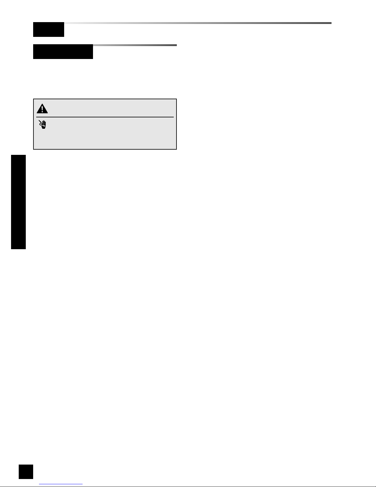
Alarm panels require 100 to 250 VAC
50/60 Hz. power. Refer to Wiring
Schematic 1 (Page. 46).
For NFPA 99 compliance, alarm panel
must be connected to life safety branch of
the emergency electrical system.
1. Remove four nuts (area alarms) or
screws (master or combo alarms) from
plastic power supply shield.
2. Remove plastic shield from power
supply.
3. Connect incoming line, neutral and
ground wires to the terminal block.
5. Reinstall plastic power supply shield
while making sure all high voltage wires
are contained within plastic shield.
6. Secure plastic shield with four nuts
(area alarms) or screws (master or
combo alarms).
Installation Procedures
Power Supply
Wiring
WARNING:
RISK OF ELECTRIC SHOCK
Disconnect power at the circuit breaker before
removing power supply shield.
Page 33
31
6-847718-00 Rev. B00
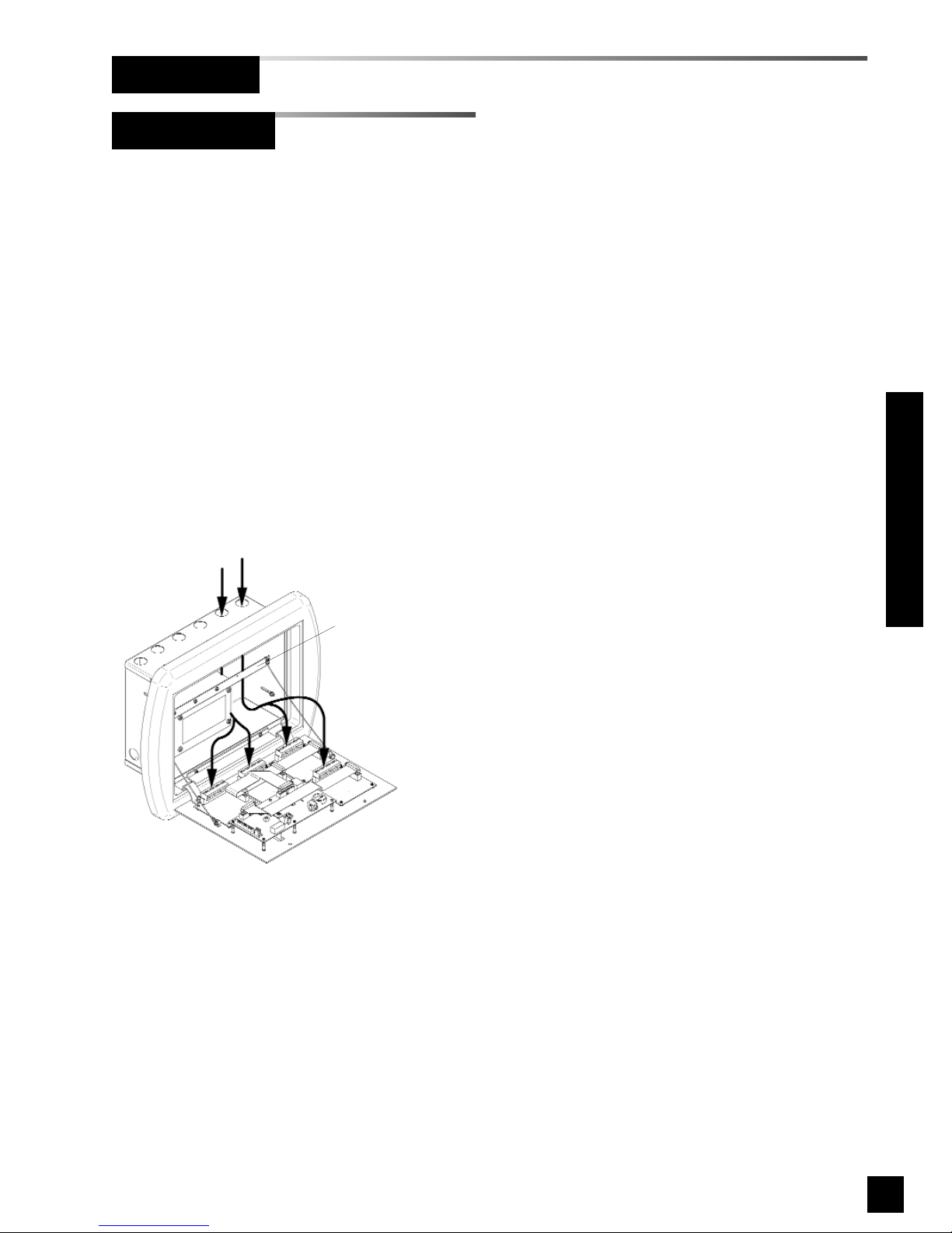
1. Identify each pair of field installed
sensor wires inside alarm panel back
box assembly.
2. Route each pair of sensor wires as
shown in Figure 23 to appropriate
digital display module. Each digital
display module is labeled with the gas
type. Verify the appropriate remote
sensor wires are connected to correct
digital display module.
3. Connect positive sensor wires to
terminals 5 and 6 for each remote
sensor and digital display module.
Refer to Wiring Schematic 2
(Page 47).
Figure 23: Remote Sensor Wire Routing
Holes provided for
entrance of remote wiring
Route wires behind
metal brace
Remote Sensor
Wiring (Cont.)
Installation Procedures
Page 34
32
6-847718-00 Rev. B00
Breakout Board Inputs
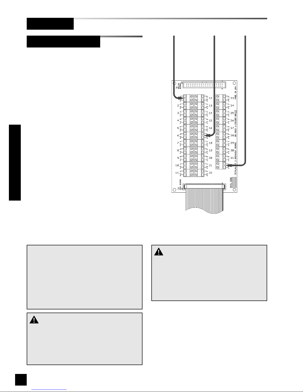
A master or combo alarm with 32 signals
has only one breakout board. Signals are
numbered A1 through A32.
A master or combo alarm with 64 signals
has two breakout boards. Signals are
labeled A1 through A32 on breakout board
A and B1 through B32 on breakout board
B.
1. Identify each pair of field installed
source equipment signal wires inside
alarm panel back box assembly.
2. Route each pair of signal wires as
shown in Figure 24 to appropriate
terminals on breakout board(s).
3. Connect each pair of signal wires to
desired breakout board terminals. The
terminals are labeled “Signal 1” through
“Signal 32”. Refer to Wiring
Schematic 3 (Page 48).
NOTE:
Each pair of terminals labeled on the multi-signal
module connector is labeled “+” and “COM”.
Ensure that when a source equipment dry contact
is wired to two master panels, the same side of
the dry contact is connected to the same terminal
at both panels. For example, if the source equipment’s normally closed contact is wired to the “+”
of the first master panel, ensure it is also connected to the “+” terminal of the second master panel.
CAUTION:
Source equipment signal wires must be connected to normally-closed, dry contacts. No electrical
voltage can be present and contacts must be
closed during normal equipment operation. When
contacts open, an alarm condition will be activated.
Wiring (Cont.)
Figure 24: Breakout Board Wire Routing
Installation Procedures
CAUTION:
Do not connect TotalAlert 2 master/combo alarm
to switch/relay contacts connected to any alarm
panels other than those listed below:
• TotalAlert 2
• MEGA2
• MEGA
Page 35

33
6-847718-00 Rev. B00
Wiring (Cont.)
Relay Board Outputs
Installation Procedures
A master or combo alarm with 32 signals
has only one relay board. Signals are
numbered A1 through A32.
A master or combo alarm with 64 signals
has two relay boards. Signals are labeled
A1 through A32 on relay board A and B1
through B32 on relay board B.
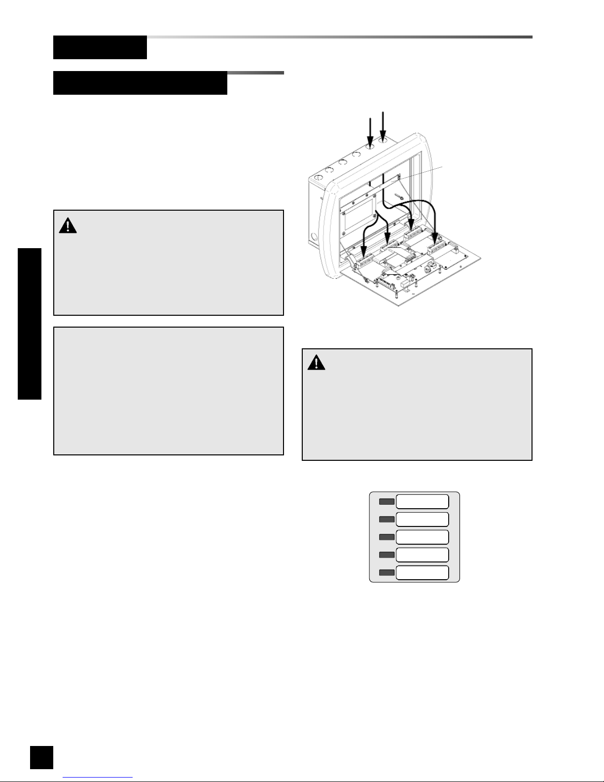
1. Identify each pair of field installed relay
output signal wires inside alarm panel
back box assembly.
2. Route each pair of relay output signal
wires as shown in Figure 25 to
appropriate terminals on relay board(s).
3. Connect each pair of signal wires to
desired relay board terminals. The
terminals are labeled “1” through “32”.
Refer to Wiring Schematic 4
(Page 49).
Figure 25: Relay Board Wire Routing
Page 36
34
6-847718-00 Rev. B00
Wiring (Cont.)
Multi-Signal Module Inputs
Installation Procedures
1. Identify each pair of field installed
source equipment signal wires inside
alarm panel back box assembly.
2. Route each pair of signal wires as
shown in Figure 26 to appropriate
multi-signal module.
3. Connect each pair of signal wires to
desired multi-signal module terminals.
The terminals are labeled “Signal 1”
through “Signal 5”. Refer to Wiring
Schematic 5 (Page 50).
Signal 1 corresponds to top row of
indicators on front panel of multi-signal
module. Signal 5 corresponds to
bottom row (Figure 27).
NOTE:
Each pair of terminals labeled on the multi-signal
module connector is labeled “+” and “COM”.
Ensure that when a source equipment dry contact
is wired to two master panels, the same side of
the dry contact is connected to the same terminal
at both panels. For example, if the source equipment’s normally closed contact is wired to the “+”
of the first master panel, ensure it is also connected to the “+” terminal of the second master panel.
Holes provided for
entrance of remote wiring
Route wires behind
metal brace
Figure 27: Multi-Signal Module Signal Numbering
Signal 1
Signal 2
Signal 3
Signal 4
Signal 5
CAUTION:
Source equipment signal wires must be connected to normally-closed, dry contacts. No electrical
voltage can be present and contacts must be
closed during normal equipment operation. When
contacts open, an alarm condition will be activated.
Figure 26: Source Equipment Wire Routing
CAUTION:
Do not connect TotalAlert 2 master/combo alarm
to switch/relay contacts connected to any alarm
panels other than those listed below:
• TotalAlert 2
• MEGA2
• MEGA
Page 37

35
6-847718-00 Rev. B00
Wiring (Cont.)
Multi-Signal Module Relays
Installation Procedures
Digital Display Module Master/Slave
Digital display modules of two alarm
panels may be wired together in such a
way that pressure readings of first panel
can be duplicated at second panel.
Each digital display module has RS-422
digital outputs and inputs. By connecting
digital output (master output) of first panel
to digital inputs (slave input) of the
second panel, second panel will duplicate
pressure readings.
Connect the master output terminals of
the sending digital display module to the
slave input terminals of the receiving digital display module.
Refer to Wiring Schematic 6 (Page 51).
As an option, mutli-signal modules may be
ordered with five output relays, one for
each of five signals that multi-signal is
capable of monitoring.
Each relay has a set of dry, normallyclosed contacts that will open when an
alarm is activated on corresponding front
panel signal. For example, when an alarm
condition activates on top multi-signal front
panel alarm location (Signal 1), relay
labeled “Signal 1” will activate opening its
contacts. Relay contacts will remain open
as long as alarm condition is active, even if
audible alarm is silenced by MUTE
button.
When alarm condition is corrected, relay
contacts will close.
Relay contact ratings are 2 A @ 30 VDC/0.5 A
@ 125 VAC.
Refer to Wiring Schematic 7 (Page 52).
Page 38

36
6-847718-00 Rev. B00
Wiring (Cont.)
Digital Display Module High / Low
Relays
Installation Procedures
Each digital display module is supplied with
two separate output relays. One relay for
high line pressure alarm and another for
low line pressure alarm.
Each relay has a set of dry, normallyclosed contacts that will open when an
alarm is activated on corresponding front
panel signal.
For example, when a low pressure alarm
condition activates on digital display
module front panel, relay labeled “Low
Relay” will activate, opening its contacts.
Relay contacts will remain open as long as
alarm condition is active, even if audible
alarm is silenced by MUTE button.
When alarm condition is corrected, relay
contacts will close.
Relay contact ratings are 2 A @ 30
VDC/0.5 A @ 125 VAC.
Refer to Wiring Schematic 9 (Page 53).
General Fault / Aux Relays
Annunciator Module General Fault Relay:
The annunciator module is supplied with
an alarm panel general fault output relay.
This relay has a set of dry contacts that
may be wired either normally open or
normally closed.
The relay will activate when ANY alarm on
ENTIRE alarm panel is activated. Relay
will remain activated as long as alarm
condition is active, even if audible alarm is
silenced by MUTE button.
When alarm condition is corrected, relay
will deactivate. Relay contact ratings are
2
A @ 30 VDC/0.5 A @ 125 VAC
. Refer to
Wiring Schematic 8
(Page 53).
Annunciator Module Auxiliary Relay:
The annunciator module is supplied with
an additional auxiliary relay.
Auxiliary relay has a set of dry contacts
that may be wired either normally open or
normally closed.
Auxiliary relay will activate when ANY
alarm on ENTIRE alarm panel is initiated.
Auxiliary relay will deactivate when audible
alarm is silenced by MUTE button.
If alarm condition is still active when mute
function cancels, auxiliary relay will
reactivate.
Relay contact ratings are 2 A @ 30
VDC/0.5 A @ 125 VAC. Refer to Wiring
Schematic 8 (Page 53).
Page 39
37
6-847718-00 Rev. B00
Installation Procedures
Wiring (Cont.)
TotalAlert 2 master and combo alarm
panels are compatible with Johnson
Controls Metasys® N2 building
automation system.
Each alarm panel is field programmed
with a unique N2 address.
Using this address, Johnson Controls
system can monitor alarm panel status
including digital pressure readings and
programmed alarm set points.
Each alarm panel is connected to a
common two-wire RS-485 serial computer
interface bus. Two wires are connected
to connector TB1 of annunciator module
and then connected to common data bus.
Refer to Wiring Schematic 11 (Page 55).
Building Automation System Mapping
The state of each of the 64 switched
inputs of a master or combo alarm is
available using BI1 through BI64.
BI65 is true if there are any active alarms.
For efficient single point monitoring, enroll
BI65 in the BAS polling table.
BI66 indicates the state of the audible
alarm.
Additional information is available using
integer data points ADI1 through ADI5.
ADI1 = device serial number, low 2 bytes.
ADI2 = device serial number, high 2
bytes.
NOTE:
The following information is intended to be
used by Information Sytems or Building
Automation personnel.
Building Automation SystemEthernet
Alarms can be connected together in a
TotalAlert alarm network.
Connect the network cable modular plug to
annunciator module modular jack J9.
Page 40

38
6-847718-00 Rev. B00
Wiring (Cont.)
Installation Procedures
Building Automation System (Cont.)
ADI3 = device firmware version.
ADI4 = number of switched inputs
indicating an alarm condition.
ADI5 = number of remote alarm modules
indicating an alarm condition.
If you are planning to use the Metasys®
building automation system with the
TotalAlert 2, request the following file from
BeaconMedaes technical support:
Filename: TotalAlert2v1.ddl
************************************************
**********************
* BeaconMedæs TotalAlert2® Medical Gas Alarm
version 1.00
* Point Type Max Allowed
* ---------------------- ----------* AD - Analog Data 32 (ADI & ADF read-only)
* BI - Binary Input
* Never map output points in a CS model and as
discrete objects.
* The N, N or Y, Y after the point label means:
* 1st one - Can be overridden
* 2nd one - Can be adjusted
************************************************
**********************
@MODEL+
CSMODEL "TotalAlert2", "VND"
BITITLE "Inputs"
ADTITLE "Alarm Summary"
CSBI "BI1" ,Y,N,"INPUT_A1","Normal","Alarm"
CSBI "BI2" ,Y,N,"INPUT_A2","Normal","Alarm"
CSBI "BI3" ,Y,N,"INPUT_A3","Normal","Alarm"
CSBI "BI4" ,Y,N,"INPUT_A4","Normal","Alarm"
CSBI "BI5" ,Y,N,"INPUT_A5","Normal","Alarm"
CSBI "BI6" ,Y,N,"INPUT_A6","Normal","Alarm"
CSBI "BI7" ,Y,N,"INPUT_A7","Normal","Alarm"
CSBI "BI8" ,Y,N,"INPUT_A8","Normal","Alarm"
CSBI "BI9" ,Y,N,"INPUT_A9","Normal","Alarm"
CSBI "BI10" ,Y,N,"INPUT_A10","Normal","Alarm"
CSBI "BI11" ,Y,N,"INPUT_A11","Normal","Alarm"
CSBI "BI12" ,Y,N,"INPUT_A12","Normal","Alarm"
CSBI "BI13" ,Y,N,"INPUT_A13","Normal","Alarm"
CSBI "BI14" ,Y,N,"INPUT_A14","Normal","Alarm"
CSBI "BI15" ,Y,N,"INPUT_A15","Normal","Alarm"
CSBI "BI16" ,Y,N,"INPUT_A16","Normal","Alarm"
CSBI "BI17" ,Y,N,"INPUT_A17","Normal","Alarm"
CSBI "BI18" ,Y,N,"INPUT_A18","Normal","Alarm"
CSBI "BI19" ,Y,N,"INPUT_A19","Normal","Alarm"
CSBI "BI20" ,Y,N,"INPUT_A20","Normal","Alarm"
CSBI "BI21" ,Y,N,"INPUT_A21","Normal","Alarm"
CSBI "BI22" ,Y,N,"INPUT_A22","Normal","Alarm"
CSBI "BI23" ,Y,N,"INPUT_A23","Normal","Alarm"
CSBI "BI24" ,Y,N,"INPUT_A24","Normal","Alarm"
CSBI "BI25" ,Y,N,"INPUT_A25","Normal","Alarm"
CSBI "BI26" ,Y,N,"INPUT_A26","Normal","Alarm"
CSBI "BI27" ,Y,N,"INPUT_A27","Normal","Alarm"
CSBI "BI28" ,Y,N,"INPUT_A28","Normal","Alarm"
CSBI "BI29" ,Y,N,"INPUT_A29","Normal","Alarm"
CSBI "BI30" ,Y,N,"INPUT_A30","Normal","Alarm"
CSBI "BI31" ,Y,N,"INPUT_A31","Normal","Alarm"
CSBI "BI32" ,Y,N,"INPUT_A32","Normal","Alarm"
CSBI "BI33" ,Y,N,"INPUT_B1","Normal","Alarm"
CSBI "BI34" ,Y,N,"INPUT_B2","Normal","Alarm"
CSBI "BI35" ,Y,N,"INPUT_B3","Normal","Alarm"
CSBI "BI36" ,Y,N,"INPUT_B4","Normal","Alarm"
CSBI "BI37" ,Y,N,"INPUT_B5","Normal","Alarm"
CSBI "BI38" ,Y,N,"INPUT_B6","Normal","Alarm"
CSBI "BI39" ,Y,N,"INPUT_B7","Normal","Alarm"
CSBI "BI40" ,Y,N,"INPUT_B8","Normal","Alarm"
CSBI "BI41" ,Y,N,"INPUT_B9","Normal","Alarm"
CSBI "BI42" ,Y,N,"INPUT_B10","Normal","Alarm"
CSBI "BI43" ,Y,N,"INPUT_B11","Normal","Alarm"
CSBI "BI44" ,Y,N,"INPUT_B12","Normal","Alarm"
CSBI "BI45" ,Y,N,"INPUT_B13","Normal","Alarm"
CSBI "BI46" ,Y,N,"INPUT_B14","Normal","Alarm"
CSBI "BI47" ,Y,N,"INPUT_B15","Normal","Alarm"
CSBI "BI48" ,Y,N,"INPUT_B16","Normal","Alarm"
CSBI "BI49" ,Y,N,"INPUT_B17","Normal","Alarm"
CSBI "BI50" ,Y,N,"INPUT_B18","Normal","Alarm"
CSBI "BI51" ,Y,N,"INPUT_B19","Normal","Alarm"
CSBI "BI52" ,Y,N,"INPUT_B20","Normal","Alarm"
CSBI "BI53" ,Y,N,"INPUT_B21","Normal","Alarm"
CSBI "BI54" ,Y,N,"INPUT_B22","Normal","Alarm"
CSBI "BI55" ,Y,N,"INPUT_B23","Normal","Alarm"
CSBI "BI56" ,Y,N,"INPUT_B24","Normal","Alarm"
CSBI "BI57" ,Y,N,"INPUT_B25","Normal","Alarm"
CSBI "BI58" ,Y,N,"INPUT_B26","Normal","Alarm"
CSBI "BI59" ,Y,N,"INPUT_B27","Normal","Alarm"
CSBI "BI60" ,Y,N,"INPUT_B28","Normal","Alarm"
CSBI "BI61" ,Y,N,"INPUT_B29","Normal","Alarm"
CSBI "BI62" ,Y,N,"INPUT_B30","Normal","Alarm"
CSBI "BI63" ,Y,N,"INPUT_B31","Normal","Alarm"
CSBI "BI64" ,Y,N,"INPUT_B32","Normal","Alarm"
CSBI "BI65" ,Y,N,"ANY_ALARM","No_Alarms","Alarm"
CSBI "BI66" ,Y,N,"AUD_ALM","Off","On"
CSAD "ADI1" ,N,Y,"Serial_1",""
CSAD "ADI2" ,N,Y,"Serial_2",""
CSAD "ADI3" ,N,Y,"VERSION",""
CSAD "ADI4" ,N,Y,"NUMBER_LOCAL_ALARMS",""
CSAD "ADI5" ,N,Y,"NUMBER_REMOTE_ALARMS",""
CSAI "AI1",Y,N,"DDM1",""
CSAI "AI2",Y,N,"DDM2",""
CSAI "AI3",Y,N,"DDM3",""
CSAI "AI4",Y,N,"DDM4",""
CSAI "AI5",Y,N,"DDM5",""
CSAI "AI6",Y,N,"DDM6",""
CSAI "AI7",Y,N,"DDM7",""
CSAI "AI8",Y,N,"DDM8",""
Page 41
39
6-847718-00 Rev. B00
Installation Procedures
Field Wiring Cable Shield Grounding
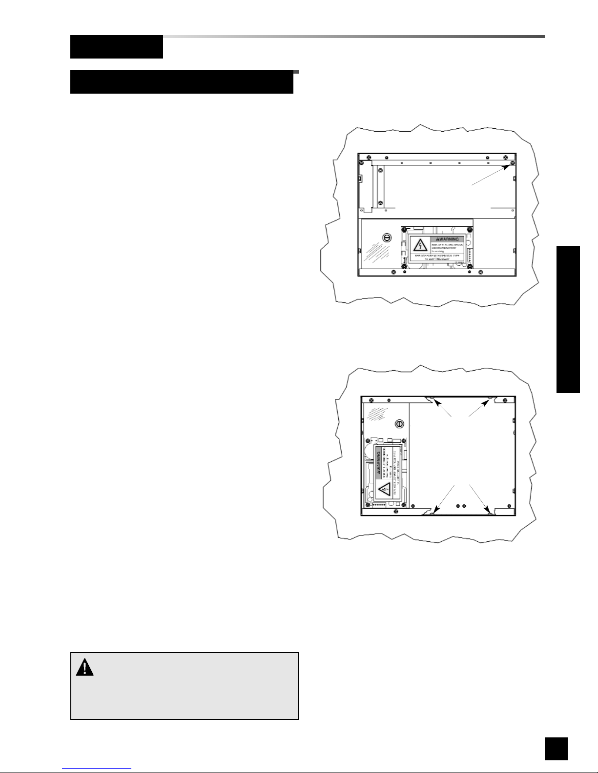
All field wiring cable shields must be
grounded inside alarm panel back box.
A grounding screw is provided in upper
right corner of area alarm back box
(Figure 28).
Grounding screws are provided in top and
bottom of master and combo alarm back
boxes (Figure 29).
Shields from several cables may be
wrapped together and crimped into one
ring lug (by others) .
Cable shield
grounding screw
(crimp lug not provided)
CAUTION:
Keep shield wires to ground screw as short as
possible so they can not touch front panel circuit
boards when front panel is closed.
Figure 29: Cable Shield Grounding-Master/Combo
Cable shield
grounding screws
located at top and
bottom of back box
(crimp lugs not provided)
Figure 28: Cable Shield Grounding-Area
Wiring (Cont.)
Page 42
40
6-847718-00 Rev. B00
Installation Procedures
Front Panel Mounting
Finish
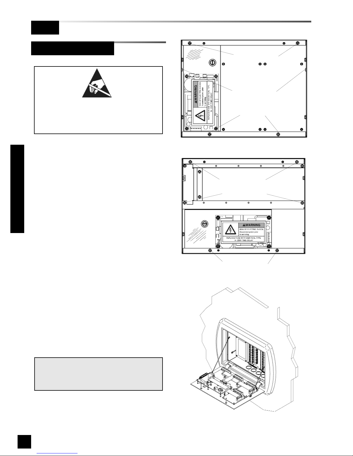
1. Remove front panel assembly from
static shielding shipping bag.
2. Remove front panel mounting screws
from alarm panel back box assembly
(Figures 30 and 31).
3. Remove lanyard mounting screws
from alarm panel back box assembly
(Figure 30 and 31).
4. Attach front panel to alarm panel back
box using screws removed in step 2
(Figure 32).
5. Attach lanyards to alarm panel back
box using screws removed in step 3.
6. Remove nut from front panel
grounding lug.
7. Install front panel grounding wire using
nut removed in step 6
8. Connect power supply DC wire
harness to J6 on annunciator module.
Refer to Wiring Schematic 1
(Page 46).
NOTE:
Harness connector is keyed to prevent incorrect orientation, however, use care to ensure
correct pin alignment.
Figure 32: Attach Front Panel and Lanyards
Figure 31: Area Alarm Panel Screws
Figure 30: Master / Combo Panel Screws
Lanyard screws
Lanyard screws
Front panel
mounting screws
Front panel
mounting screws
Front panel
mounting screws
Front panel
mounting screws
ATTENTION:
Observe Precautions for Handling
ELECTROSTATIC SENSITIVE
DEVICES
Page 43
41
6-847718-00 Rev. B00
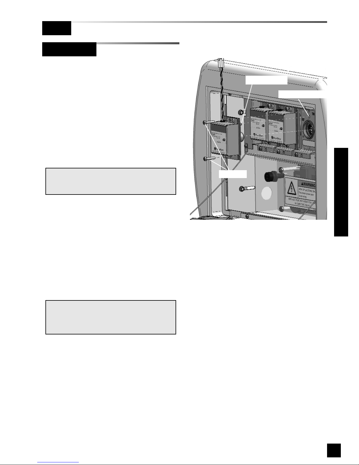
1. Remove sensor module from shipping
carton.
2. Insert sensor into valve opening in
pressure/vacuum service rough-in
(Figure 33). An indexing pin provides
for proper orientation and prevents
gas service cross-connection. Push
sensor all the way in and secure with
(2) #6-32 x 1-1/4” screws. Repeat this
process for all sensors within alarm
panel.
3. The digital display module(s) located
on front panel assembly are factory
wired with a harness and polarized
two-pin connector for each sensor
module. Each digital display module
is labeled with the gas type. Match
gas type of each sensor to gas type of
each digital display module and join
polarized connectors of sensor and
digital display module harnesses.
NOTE:
Remove blue protective netting from sensor
connector.
Local Sensor
Figure 33: Local Sensor Mounting
Finish
Installation Procedures
Indexing Pin
Indexing Hole
Screws
NOTE:
Pressure/vacuum service rough-ins have been
installed in a specific order to optimize sensor
module wire routing.
Page 44
42
6-847718-00 Rev. B00
Installation Procedures
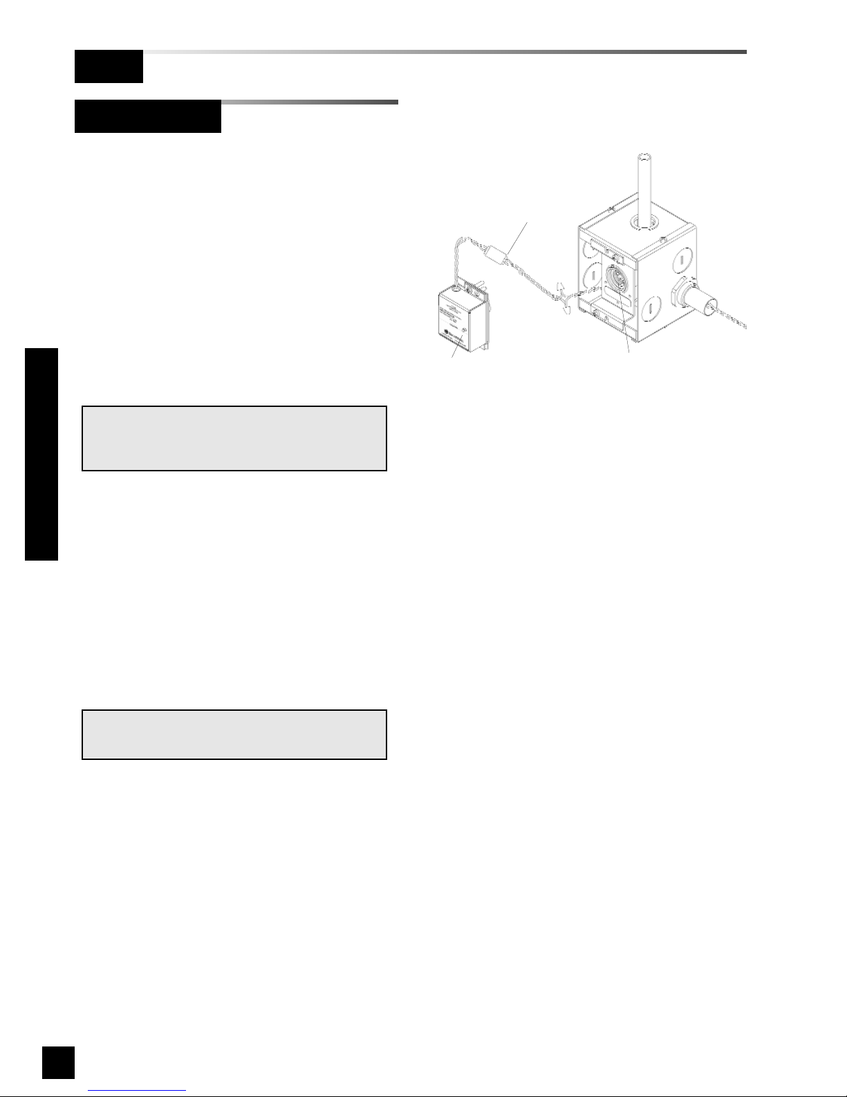
1. Remove sensor module from shipping
carton. Each sensor module is
shipped with a wiring pigtail that has a
two-pin polarized connector.
2. Wire nut pigtail to field installed wiring
inside sensor mounting box. Note
polarity of wiring and corresponding
field wiring color or number for later.
3. Join polarized connector in sensor
mounting box to mating connector on
sensor module (Figure 34).
4. Insert sensor into valve opening in
sensor rough-in. An indexing pin
provides for proper orientation and
prevents gas service crossconnection. Push sensor all the way
in and secure with (2) #6-32 x 1-1/4”
screws.
5. Tuck excess wiring into open space
behind sensor.
NOTE:
Remove blue protective netting from sensor
connector.
Figure 34: Remote Sensor Module Connection
Remote Sensor
Valve opening
Sensor
Polarized
connector
Finish
NOTE:
Do not ground shield drain wire at sensor.
Page 45
43
6-847718-00 Rev. B00
Labeling
Finish
Installation Procedures
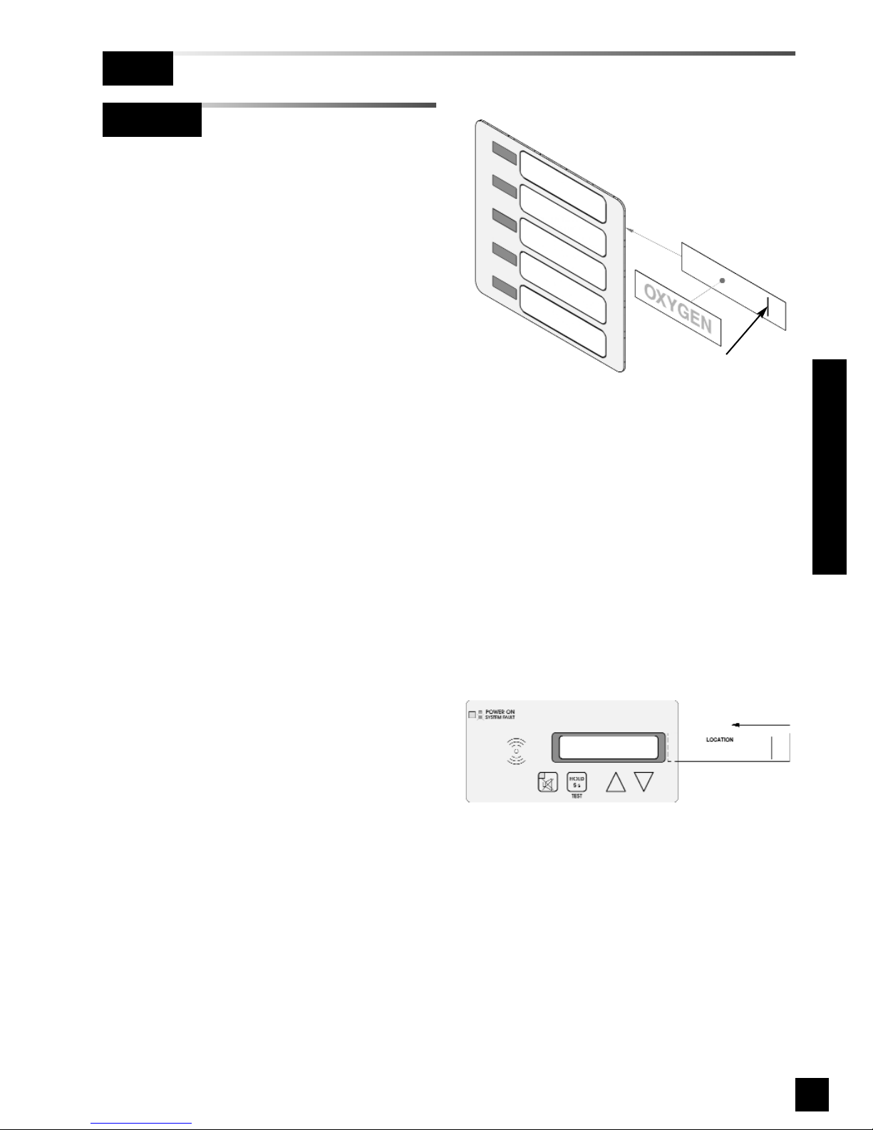
Annunciator Module (Area Alarms)
Label annunciator module using provided
panel location label.
1. Mark location on panel location label.
2. Slide location label into pocket in front
of annunciator module (Figure 36).
Figure 36: Annunciator Module Location Label
Multiplexer Module/LED Module
Label each LED using the provided gas
service identification labels.
Multiplexer module LEDs are numbered 1
through 5 from top to bottom.
LED module LEDs are numbered 6
through 10 from top to bottom.
1. Apply gas identification label to insert.
2. Slide insert with label into pocket in
front of multiplexer or led module
(Figure 35).
Align gas ID label
with line on insert
Figure 35: Multiplexer Module Labeling
Page 46
44
6-847718-00 Rev. B00
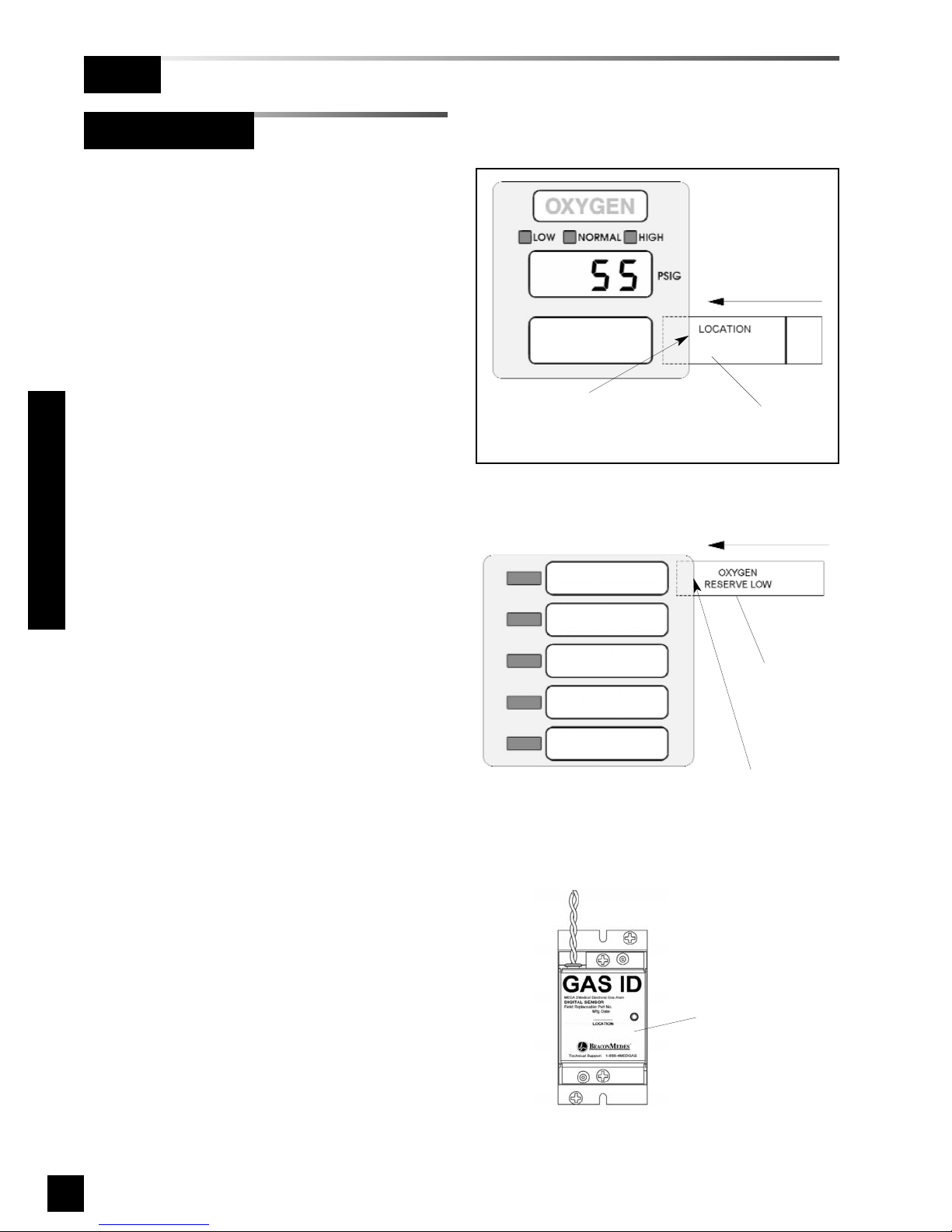
Label
(provided)
Slide label into slit in
front panel overlay
Digital Display Module
Label each digital display module using
provided location labels.
1. Mark location on location label.
2. Slide location label into pocket in front
of digital display module (Figure 37).
Multi-Signal Module
Label each multi-signal module using
provided system status labels.
Blank system status labels are provided for
custom signal names.
1. Slide system status labels into pockets
in front of multi-signal module
(Figure 38).
Installation Procedures
Labeling (Cont.)
Finish
Label
(provided)
Slide label(s) into slits
in front panel overlay
Location label
Sensor Module
1. Mark location monitored by sensor in
space provided on sensor label
(Figure 39).
Figure 39: Sensor Module Location Label
Figure 38: Multi-Signal Front Panel Labeling
Figure 37: Digital Display Module
Page 47

45
6-847718-00 Rev. B00
The wiring schematics listed below are
provided.
Call BeaconMedæs at 1-888-4MEDGAS
(1-888-463-3427) for technical support.
1. Power Supply (Page 46)
2. Sensor Module to Digital Display
Module (Page 47)
3. Multiplexer/Breakout Boards (Page 48)
4. Relay Board (Page 49)
5. Multi-Signal Module Inputs (Page 50)
6. Digital Display Module Master/Slave
(Page 51)
7. Multi-Signal Module Relay Outputs
(Page 52)
8. General Fault/Auxiliary Relays
(Page 53)
9. Digital Display Module High/Low Relays
(Page 53)
10 Remote Pressure/Vacuum Switches
(Page 54)
11 Johnson Controls Metasys® N2
Connection (Page 55)
Wiring Schematics
Page 48
46
6-847718-00 Rev. B00
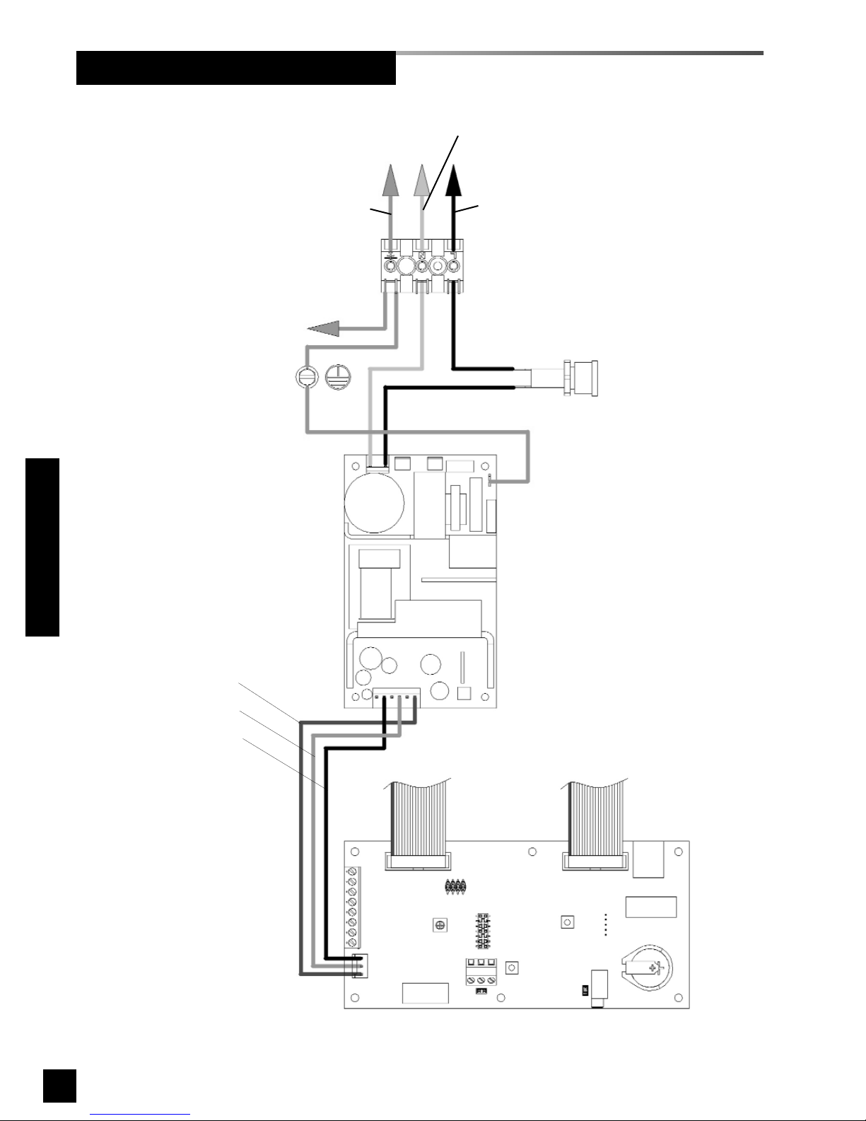
Wiring Schematic 1: Power Supply
Annunciator module
20-wire ribbon
cable to modules
Power supply
Fuse holder
Ground (green)
Line (black)
Neutral (white)
3-wire power
supply harness
120 VAC mains power connections from life safety branch of the emergency electrical system
Ground screw
Red
Orange
Black
20-wire ribbon
cable to modules
Terminal block
Ground wire To front panel
Wiring Schematics
Page 49
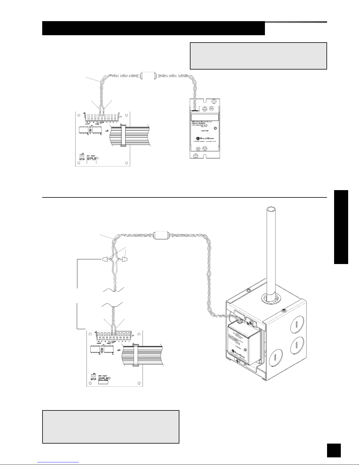
47
6-847718-00 Rev. B00
Wiring Schematic 2: Sensor Module to Digital Display Module
Digital Display Module
Digital Display Module
Remote sensor mounting box
(remote from alarm panel)
Local Sensor
(inside alarm panel back box)
2-pin polarized connector
2-pin polarized connector
20 wire
ribbon cable
to adjacent
module
LOCAL SENSOR
REMOTE SENSOR
20 wire
ribbon cable
to adjacent
module
* Sensor pigtail
Sensor pigtail
(provided)
Wire nuts
Field wiring
(by others)
* NOTE:
Sensor pigtails for local sensors are factory connected to digital display module.
Pin 5 - red (+)
Pin 6 - black (-)
Pin 5 (+)
Pin 6 (-)
NOTE:
Field wiring cable shields must be grounded at
only one end, inside alarm panel back box. Refer
to page 39 for details.
GAS ID
Wiring Schematics
Page 50
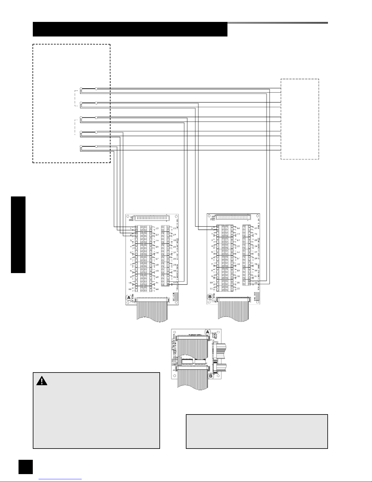
48
6-847718-00 Rev. B00
Wiring Schematic 3: Multiplexer / Breakout Boards
Wiring Schematics
20-wire ribbon cable
to modules
10-wire ribbon cable
to LED module
40-wire ribbon cable
to multiplexer module
connector A
40-wire ribbon cable
to multiplexer module
connector B
Multiplexer module
SIGNAL B32
SIGNAL B1
SIGNAL A32
SIGNAL A2
SIGNAL A1
Dry normally-closed
contacts at source
equipment or line
pressure switches
COM
+
COM
+
COM
+
COM
+
COM
+
NOTE:
Field wiring cable shields must be grounded at
only one end, inside alarm panel back box. Refer
to page 39 for details.
To additional
master alarm
panel(s)
Breakout
board A
Breakout
board B
CAUTION:
Do not connect TotalAlert 2 master/combo
alarm to switch/relay contacts connected to
any alarm panels other than those listed
below:
• TotalAlert 2
• MEGA2
• MEGA
Page 51
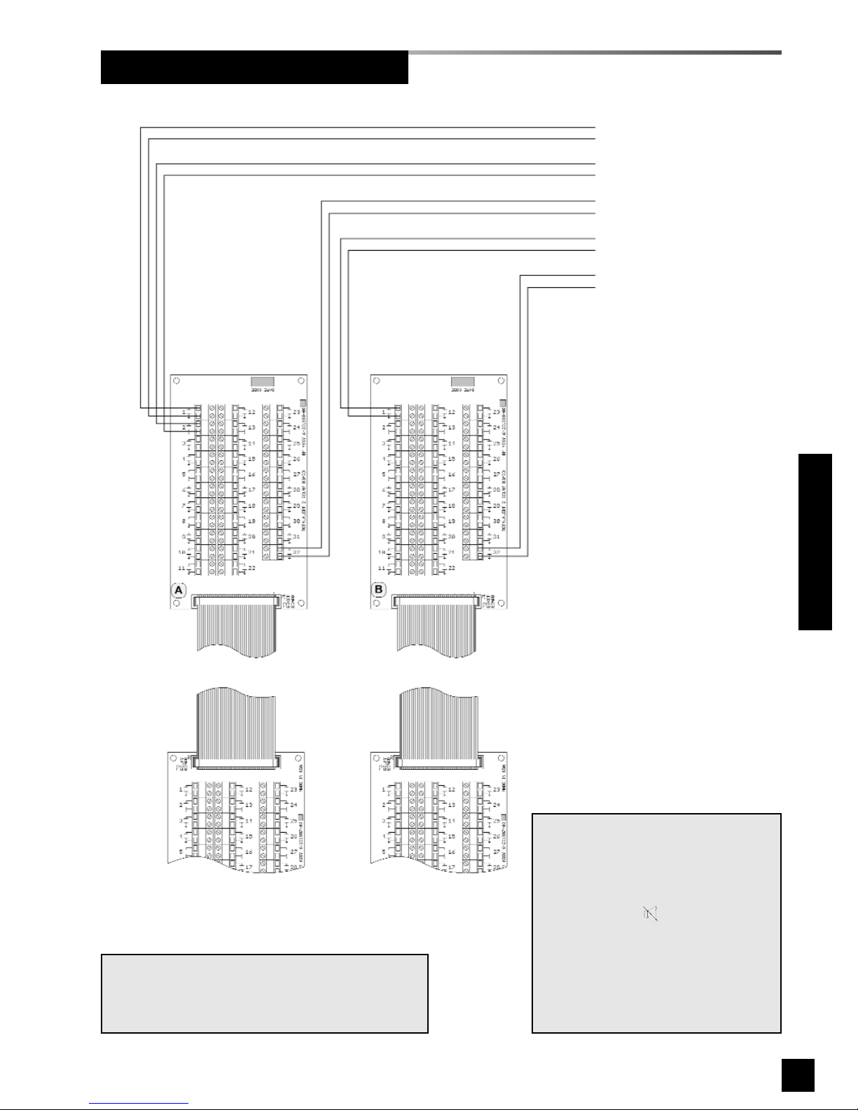
49
6-847718-00 Rev. B00
Wiring Schematic 4: Relay Board
Wiring Schematics
Breakout
board B
Breakout
board A
Relay
board A
Relay
board B
Dry normally-closed
output relay contacts
NOTE:
Output relay contacts are dry normally closed type. Contacts open upon
designated alarm activation.
Pressing MUTE on Annunciator
Module DOES NOT reset relay.
Relay deactivates when alarm condition is corrected.
Relay contact ratings are 2 A @ 30
VDC/0.5 A @ 125 VAC
.
NOTE:
Field wiring cable shields must be grounded at
only one end, inside alarm panel back box. Refer
to page 39 for details.
SIGNAL A1
SIGNAL A2
SIGNAL A32
SIGNAL B1
SIGNAL B32
Page 52
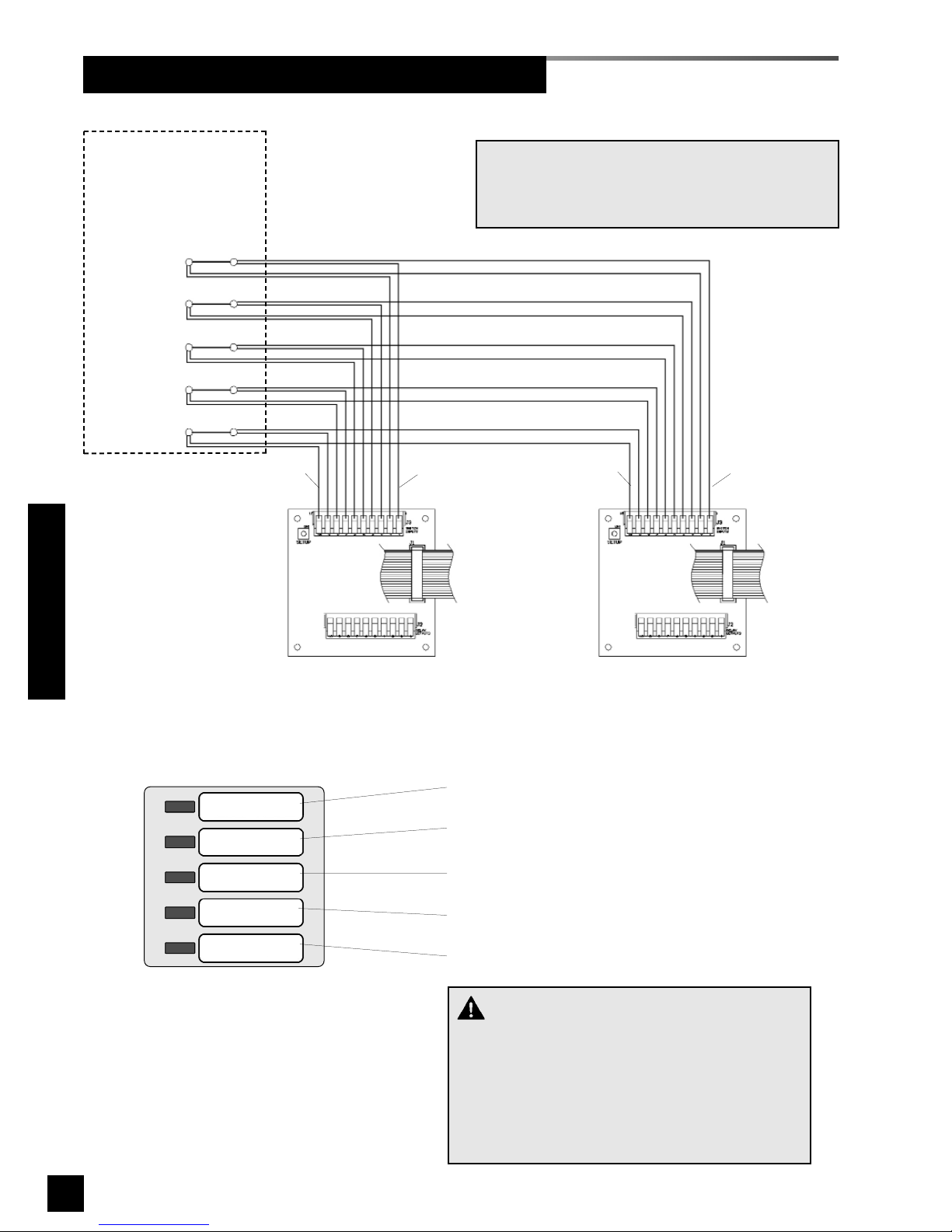
50
6-847718-00 Rev. B00
Wiring Schematic 5: Multi-Signal Module Inputs
SIGNAL 1
SIGNAL 2
SIGNAL 3
SIGNAL 4
SIGNAL 5
Dry normally-closed
contacts at source
equipment or line
pressure switches
COM
+
COM
+
COM
+
COM
+
COM
+
20 wire
ribbon cable
to adjacent
module
20 wire
ribbon cable
to adjacent
module
Pin 1
Pin 10
Pin 1
Pin 10
Multi-Signal Module
at FIRST master alarm panel
Multi-Signal Module
at SECOND master alarm panel
SIGNAL 1 - pin 1 (+), pin 2 (COM)
SIGNAL 2 - pin 3 (+), pin 4 (COM)
SIGNAL 3 - pin 5 (+), pin 6 (COM)
SIGNAL 4 - pin 7 (+), pin 8 (COM)
SIGNAL 5 - pin 9 (+), pin 10 (COM)
Multi-Signal Module front panel
NOTE:
Field wiring cable shields must be grounded at
only one end, inside alarm panel back box. Refer
to page 39 for details.
“M” OR “R” Module
Wiring Schematics
CAUTION:
Do not connect TotalAlert 2 master/combo alarm
to switch/relay contacts connected to any alarm
panels other than those listed below:
• TotalAlert 2
• MEGA2
• MEGA
Page 53
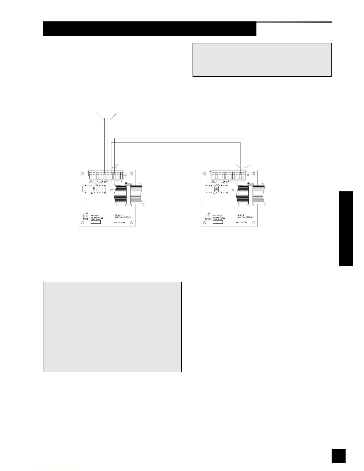
51
6-847718-00 Rev. B00
Wiring Schematic 6: Digital Display Module Master/Slave
Digital Display Module
at master alarm panel
Digital Display Module
at slave alarm panel
Signal from
sensor module
Pin 5 (+)
Pin 6 (-)
Master output
to slave
Pin 4 (-) / Pin 3 (+)
Slave input
from master
Pin 1 (+)
Pin 2 (-)
20 wire
ribbon cable
to adjacent
module
20 wire
ribbon cable
to adjacent
module
NOTE:
The above master to slave wiring configuration
DOES NOT comply with NFPA 99 wiring guidelines for two required master panels.
If digital display modules are used for a master
alarm, EACH master panel must be directly connected to a sensor module for each pressure/vacuum service.
Additional panels, if desired, may be connected
as indicated above.
NOTE:
Field wiring cable shields must be grounded at
only one end, inside alarm panel back box. Refer
to page 39 for details.
Wiring Schematics
Page 54
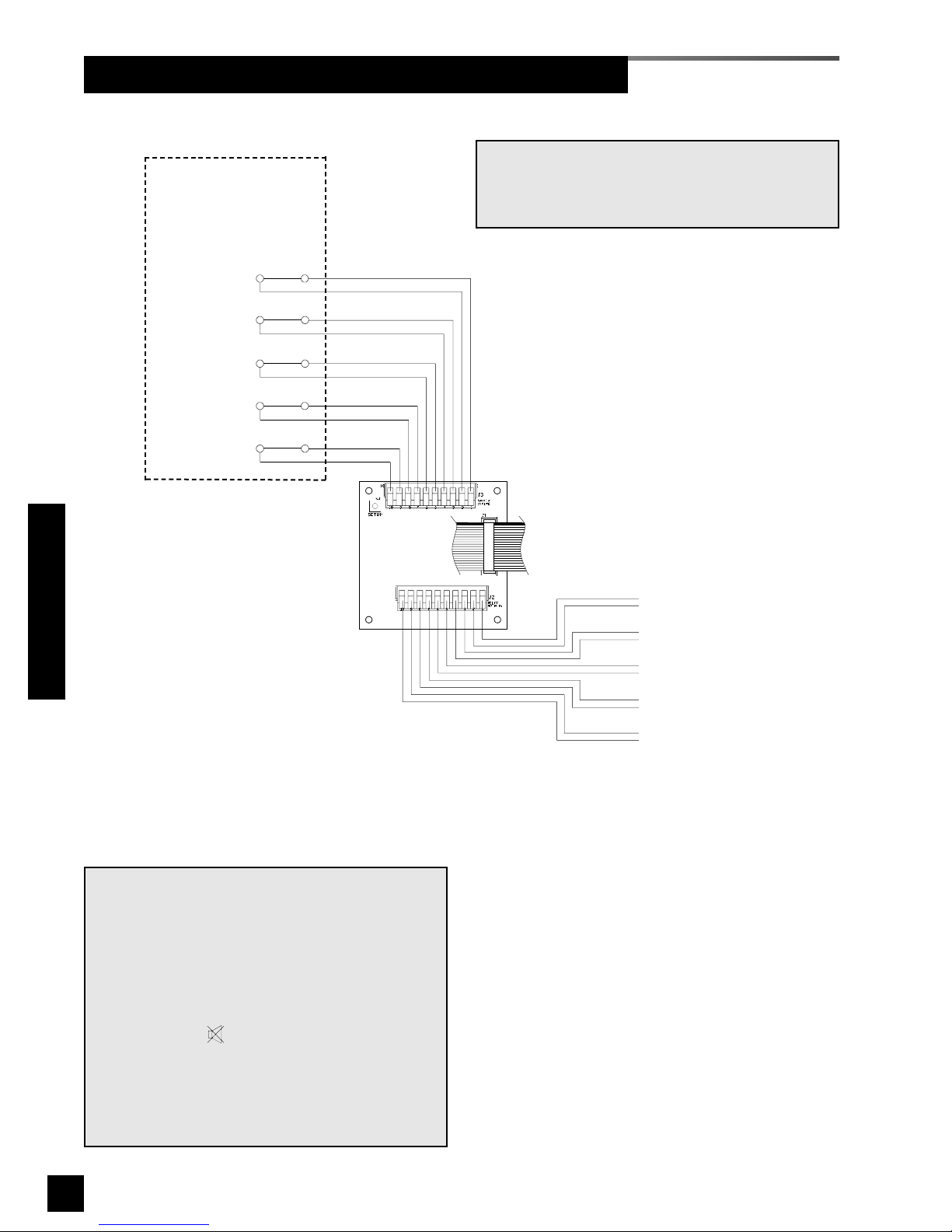
52
6-847718-00 Rev. B00
Wiring Schematic 7: Multi-Signal Module Relay Outputs
SIGNAL 1
SIGNAL 2
SIGNAL 3
SIGNAL 4
SIGNAL 5
Dry normally-closed
contacts at source
equipment or line
pressure switches
COM
+
COM
+
COM
+
COM
+
COM
+
Multi-Signal Module
with relays
20 wire
ribbon cable
to adjacent
module
SIGNAL 1 - pins 1 & 2
SIGNAL 2 - pins 3 & 4
SIGNAL 3 - pins 5 & 6
SIGNAL 4 - pins 7 & 8
SIGNAL 5 - pins 9 & 10
Dry normally-closed
output relay contacts
NOTE:
Output relay contacts are dry normally closed
type.
Contacts open upon designated alarm activation.
Contacts remain open until alarm condition is corrected.
Pressing MUTE on Annunciator Module WILL
deactivate relay until audible alarm is again reactivated.
Relay contact ratings are 2 A @ 30 VDC/0.5 A @ 125
VAC
.
NOTE:
Field wiring cable shields must be grounded at
only one end, inside alarm panel back box. Refer
to page 39 for details.
Wiring Schematics
Page 55
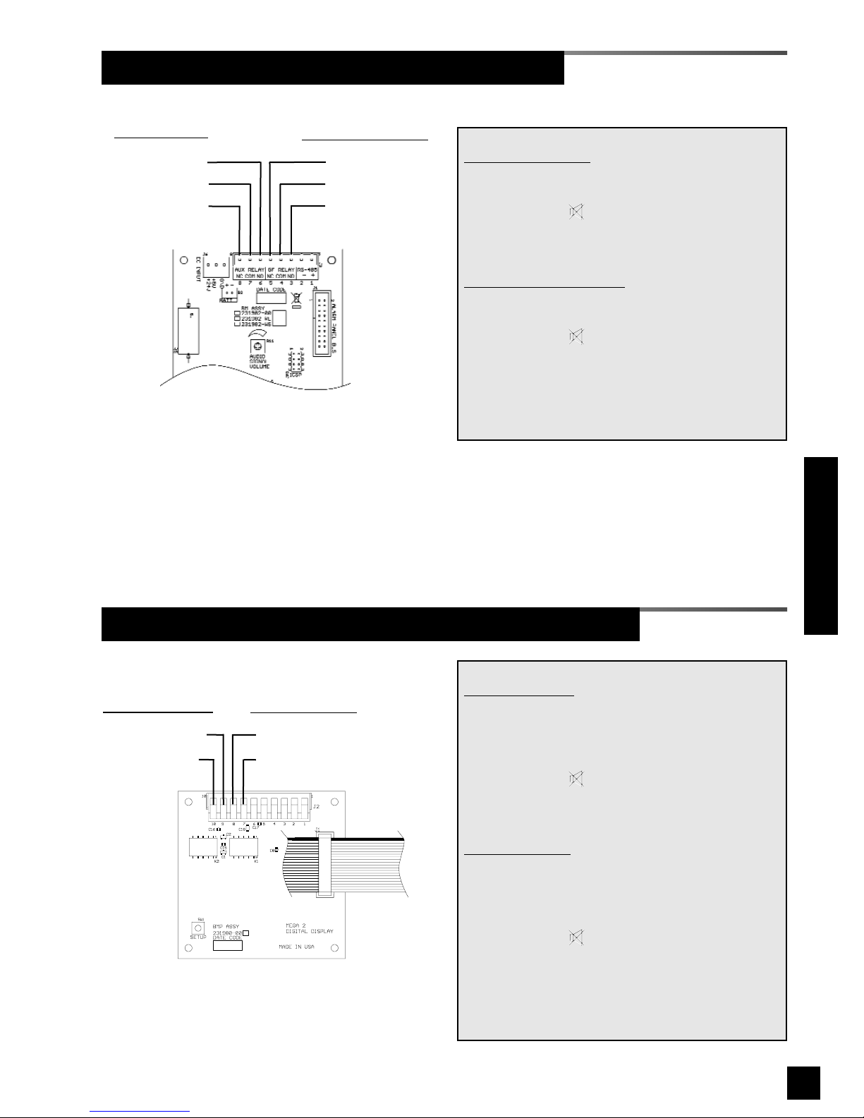
53
6-847718-00 Rev. B00
Wiring Schematic 8: General Fault / Auxiliary Relays
Wiring Schematic 9: Digital Display Module High / Low Relays
Annunciator Module
Digital Display Module
20 wire
ribbon cable
to adjacent
module
General Fault Relay
N/C (pin 5)
N/O (pin 3)
Common (pin 4)
N/O (pin 6)
Common (pin 7)
N/C (pin 8)
Auxiliary Relay
NOTE:
General Fault Relay
activates when ANY alarm
on panel is in progress.
Pressing MUTE on Annunciator Module DOES
NOT reset relay. Relay deactivates when alarm
condition is corrected.
Auxiliary Relay (optional)
activates when ANY
audible alarm on panel is in progress.
Pressing MUTE on Annunciator Module WILL
deactivate relay until audible alarm is again reactivated.
Relay contact ratings are 2A @ 30 VDC/0.5 A @
125 VAC.
20 wire
ribbon cable
to adjacent
module
Low Alarm Relay
N/C (pin 8)
Common (pin 7)
N/C (pin 10)
Common (pin 9)
High Alarm Relay
NOTE:
High
Alarm Relay activates when high line pressure alarm on digital display module is in
progress. When relay activates normally closed
contacts open.
Pressing MUTE on Annunciator Module DOES
NOT deactivate relay. Relay deactivates when
high line pressure alarm condition is corrected.
Low
Alarm Relay activates when low line pressure
alarm on digital display module is in progress.
When relay activates normally closed contacts
open.
Pressing MUTE on Annunciator Module DOES
NOT deactivate relay. Relay deactivates when
low line pressure alarm condition is corrected.
Relay contact ratings are 2A @ 30 VDC/0.5 A @
125 VAC.
Wiring Schematics
Page 56
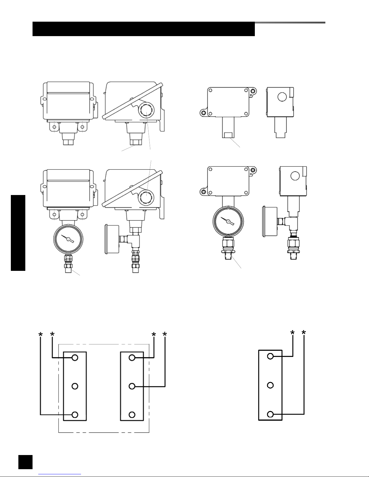
54
6-847718-00 Rev. B00
Wiring Schematic 10: Remote Pressure / Vacuum Switches
P/N 6-129030-XX thru 6-129032-XX Series
Pressure Switches
P/N 6-129033-XX Series
Vacuum Switches
* Terminals to be
used for TotalAlert 2
and other systems
sensing fault on
electrical contacts
opening.
Typical Wiring Schematic for above
Pressure Switches
Typical Wiring Schematic for above
Vacuum Switches
1/4” NPT Female
3/4” Female Conduit
Connection
1/4” NPT Female
1/4” NPT Male x DISS Valve
(Vacuum or WAGD)
1/4” NPT Male x DISS Valve
(Gas Specific)
HIGH
LOW LOW
N/C
N/O
C C
N/O
N/C
C
N/O
N/C
Wiring Schematics
Page 57
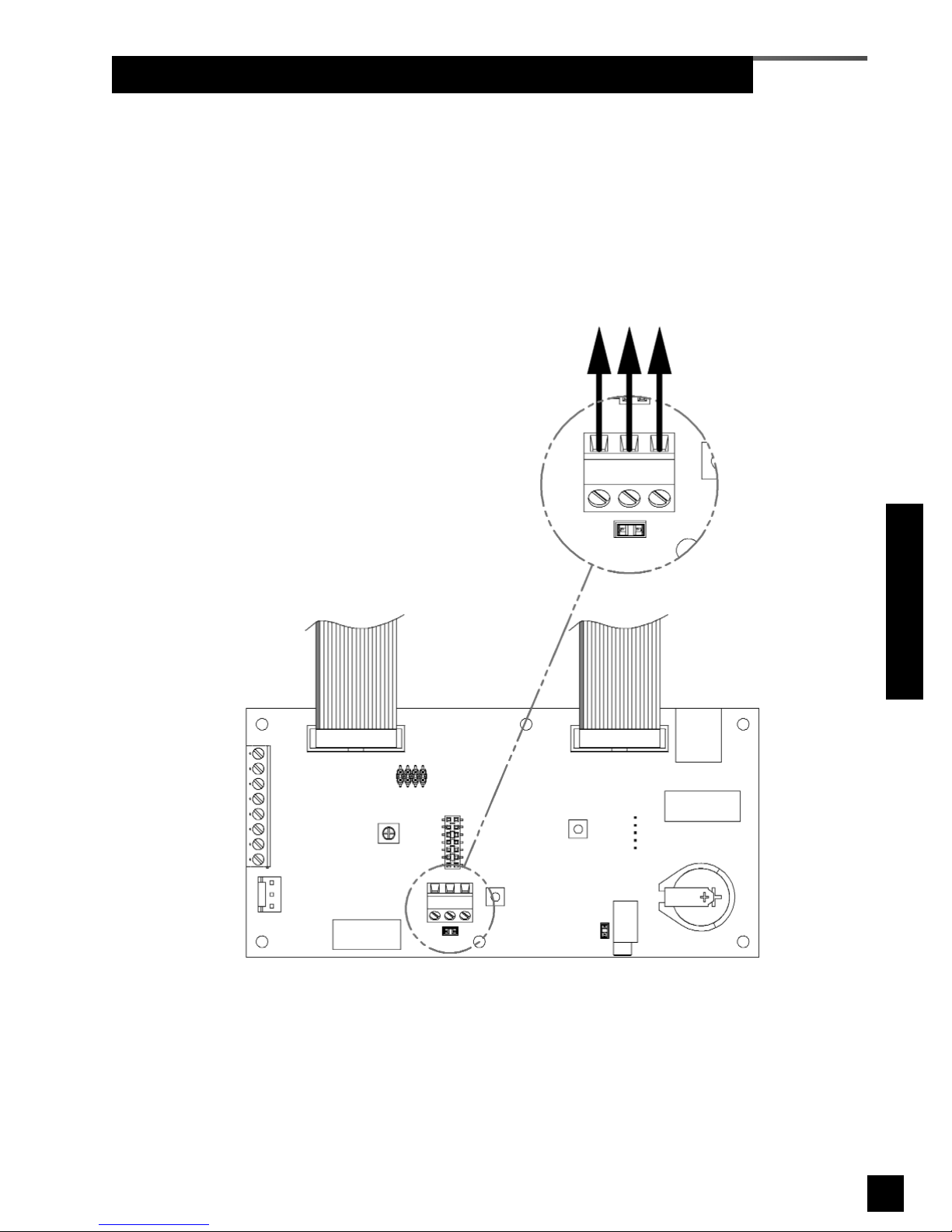
55
6-847718-00 Rev. B00
Wiring Schematic 11: Johnson Controls Metasys® N2 Connection
Wiring Schematics
To Johnson Controls Metasys®
N2 Building Automation
Annunciator Module
GND - +
RS-485
Page 58
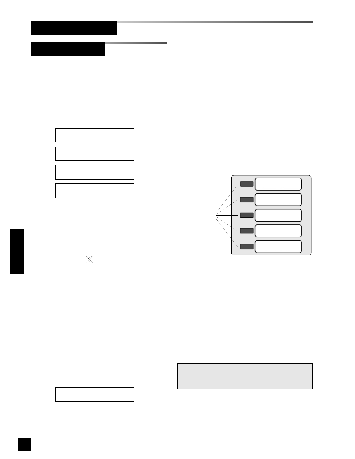
56
6-847718-00 Rev. B00
NOTE:
If any module appears to be malfunctioning, refer
to Troubleshooting Guide.
Status LEDs
1. Turn on electrical power to alarm
panel.
2. Make following observations:
• POWER ON light illuminates on
front of alarm panel.
• Boot message is shown on
vacuum fluorescent display.
• Alarm modules warm-up for ten
seconds. During warm-up, no
audible or visual alarms activated.
After warm-up, audible and visual
alarms are initiated for any active
alarm.
3. Press MUTE button to silence
audible alarm.
4. Make following observations:
• If all signals are unprogrammed
(factory default) LEDs will
illuminate green for 10 seconds,
then turn off.
• If signals are assigned to LEDs,
multiplexer and LED modules
indicate current status for the
signals and vacuum fluorescent
display displays signal information.
• Connected, but unprogrammed
signals are shown on the vacuum
fluorescent display.
Unassigned
Input [INPUT NUMBER]
Browse at: http://
TA2_12345
Version: [VERSION]
SN 12345
BeaconMedaes
TotalAlert 2 System
Booting...
Master Alarm Panel
Start-Up and Checking
Operation
Figure 40: Multiplexer/LED Module
Page 59
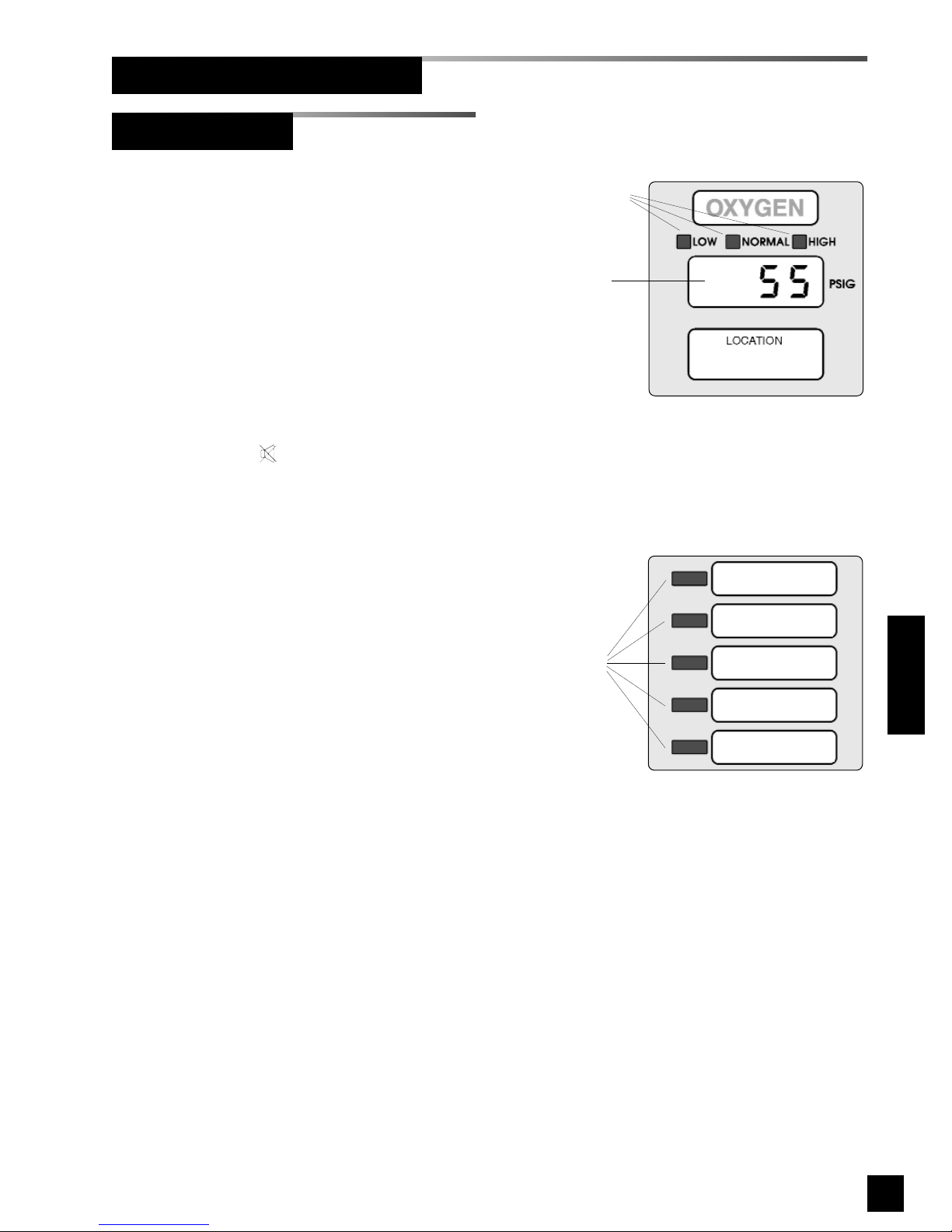
57
6-847718-00 Rev. B00
Status LEDs
LED Display
SIGNAL #1
SIGNAL #2
SIGNAL #3
SIGNAL #4
SIGNAL #5
Status LEDs
Operation
Start-Up and Checking (Cont.)
1. Turn on electrical power to alarm
panel.
2. Make following observations:
• Green POWER ON LED
illuminates on front of alarm panel.
• Alarm modules warm-up for ten
seconds. During warm-up, no
audible or visual alarms activated.
After warm-up, audible and visual
alarms are initiated for any active
alarm.
3. Press MUTE button to silence
audible alarm.
4. Pressurize piping system (medical gas
and vacuum).
5. Make following observations:
• Digital display modules display
actual pipeline pressures or
vacuum levels.
• If digital display module pipeline
pressures and vacuum levels are
within pre-set limits, NORMAL LED
is illuminated.
• If digital display module pipeline
pressures and vacuum levels are
outside pre-set limits, status LEDs
show HIGH or LOW.
• If a fault code is displayed (
-- FF 11 --
,
-- FF 22 --, -- FF 33 --
or
-- FF 44 --
) refer to
Troubleshooting Guide.
• Multi-signal modules indicate
current status from dry-contact
switches. Unused signals can be
disabled. Refer to Set-Up
Procedure.
Area Alarm Panel
Figure 42: Multi-signal Module
Figure 41: Digital Display Module
Page 60
58
6-847718-00 Rev. B00
Operation
Combo Alarm Panel
Start-Up and Checking (Cont.)
1. Turn on electrical power to alarm
panel.
2. Make following observations:
• POWER ON light illuminates on
front of alarm panel.
• Boot message is shown on
vacuum fluorescent display.
• Alarm modules warm-up for ten
seconds. During warm-up, no
audible or visual alarms activated.
After warm-up, audible and visual
alarms are initiated for any active
alarm.
3. Press MUTE button to silence
audible alarm.
4. Pressurize piping system (medical gas
and vacuum).
5. Make following observations:
• Digital display modules display
actual pipeline pressures or
vacuum levels.
• If digital display module pipeline
pressures and vacuum levels are
within pre-set limits, NORMAL
indicator is illuminated.
• If digital display module pipeline
pressures and vacuum levels are
outside pre-set limits, status
indicators show HIGH or LOW.
• If a fault code is displayed (
-- FF 11 --
,
-- FF 22 --, -- FF 33 --
or
-- FF 44 --
) refer to
Troubleshooting Guide.
Browse at: http://
TA2_12345
Version: [VERSION]
SN 12345
BeaconMedaes
TotalAlert 2 System
Booting...
• Multiplexer modules indicate current
status from dry-contact switches.
• Connected, but unprogrammed
signals are shown on the vacuum
fluorescent display.
Unassigned
Input [INPUT NUMBER]
Page 61
59
6-847718-00 Rev. B00
Operation
Annunciator Module
Set-Up Procedures
Setup Using Front Panel Controls
(Master and combo alarm panels)
Many parameters may be set using front
panel controls, but some parameters must
be set up using web pages.
1. Press SETUP button on back of
annunciator module to enter setup
mode.
2. N2 Address
This parameter is the Johnson Controls
Metasys® N2 Address.
Possible values are:
1- 255 (Factory default: 1)
3. Clear Network
Answering ‘Yes’ will clear and rebuild
the medical gas network.
4. Reset Users
Answering Yes will clear all user ids
and reset User 1 name and password
to factory defaults:
Username: new
Password: new
Reset users
[YES/NO]
Clear network
[YES/NO]
N2 Address
[VALUE]
Press or to
change the value
Press ‘TEST’ for
the next item
**** Device ****
**** Setup ****
NOTE:
Before setting up signals, fill out Master Alarm
Signal Input Data table on page 138.
5. Input gas type
Sets the gas type for signal XXX.
Possible GAS TYPES are:
Oxygen
Nitrous Oxide
Medical Air
Vacuum
Nitrogen
Lab Air
Lab Vacuum
Argon
Instrument Air
WAGD
Carbon Dioxide
CO2-O2
O2-CO2
He-O2
O2-He
Helium
Custom
Unused
Dental Air
If gas type is set to ‘Unused’, step 5 is
repeated for the next input number.
6. Input Message
Sets the alarm message for signal
XXX.
There are several pre-programmed
messages or a custom message can
be selected. A custom message must
be entered using web page setup.
Possible values depend on gas type
selected in previous step (See Table 1).
7. Input lights LED
Assigns LED to signal XXX.
Possible values are 1 - 10 for master
and large combo alarms, and 1 - 5 for
small combo alarms.
Input XXX lights
LED [LED Number]
Input XXX message
[Message]
Input XXX gas type
[GAS TYPE]
Page 62
60
6-847718-00 Rev. B00
Operation
Set-Up Procedures
Annunciator Module (Cont.)
Signal
Oxygen
Nitrous Oxide
Medical Air
Vacuum
Nitrogen
Laboratory Air
Laboratory Vacuum
Argon
Instrument Air
WAGD
Carbon Dioxide
CO2-O2
O2-CO2
He-O2
O2-He
Helium
Custom Gas Type
Dental Air
Liquid Level Low
X X X X X
High Line Pressure
X X X X X X X X X X X X X X
X
Low Line Pressure
X X X X X X X X X X X X X X
X
Reserve Pressure Low
X X X X X X X X X X X X X X
X
Main Supply Lvl. Low
X X X X X X X X X X X
2nd Supply in Use
X X X X X X X X X X X X X X
X
Resrv. Supply in Use
X X X X X X X X X X X X X X
X
Reserve Supply Low
X X X X X X X X X X X X X X
X
System Malfunction
X X X X X X X
X
Thermal Shutdown
X X X X X X X
X
Service Required
X X X X X X X
X
Backup Vac Pump On
X X X X
Low Vacuum
X X X X
Low Water
X X X X
Dryer Malfunction
X X X X
X
Dew Point High
X X X X
X
Carbon Monoxide High
X X X X
X
Change Filter
X X X X
X
Receiver Water High
X X X X
X
Separator Water High
X X X X
X
Air Disch. Temp High
X X X X
X
Backup Compressor On
X X X X
X
Compressor Malfunc.
X X X X
X
Cylinder Rsrv.in Use
X X X X
X
Cylinder Reserve Low
X X X X
X
Secondary Supply Low
X X X X X X X X X X X X X X
X
Custom Message
X X X X X X X X X X X X X X X X X
X
Table 1. Predefined Messages
Page 63
61
6-847718-00 Rev. B00
Set-Up Procedures
Operation
Only unused LEDs and LEDs with the
same gas type are available.
8. Return to step 5 for remaining inputs.
9. After setting up Input B32 the alarm
panel will return to monitoring mode.
10.To return to monitoring mode without
setting up every signal, press SETUP
button again.
Reset Users and IP Configuration
1. While holding the SETUP button, press
and release the RESET button.
2. Continue to hold the SETUP button for
5 seconds.
3. The parameters listed in Table 2 will be
set to factory defaults.
Reset Factory Defaults
1. While holding the SETUP button, press
and release the RESET button.
2. Continue to hold the SETUP button for
10 seconds.
3. The parameters listed in Tables 2 and 3
will be set to factory defaults.
Annunciator Module (Cont.)
Setting Factory default
User 1 Name new
User 2 Name [Blank]
User 3 Name [Blank]
User 1 Password new
User 2 Password [Blank]
User 3 Password [Blank]
IP address mode
Try DHCP, then try
fixed IP address
Subnet mask 255.255.255.0
Default fixed IP
address
192.168.1.100
Default fixed subnet
mask
255.255.255.0
Default fixed gateway192.168.1.1
Automatic discovery Enabled
Date/Time format 24 hours
SMTP server
address
0.0.0.0 (unused)
CAUTION:
This procedure will revert annunciator module settings to factory defaults. There is no way to
recover previously programmed settings after
resetting factory defaults.
Table 2. Reset Users and IP Config.
Setting Factory default
Facility [Blank]
Contact [Blank]
Location [Blank]
SMTP server name [Blank]
Email address 1 [Blank]
Email address 2 [Blank]
Email address 3 [Blank]
Email address 4 [Blank]
Email address 5 [Blank]
All area locations [Blank]
Peer network device list
Cleared (including
manually entered
devices)
Event log Cleared
All signal gas types Unused
All signal LEDs 0 (unassigned)
All signal locations [Blank]
All signal messages Input XXX
All custom gas types "Custom"
Table 3. Reset Factory Defaults
Page 64
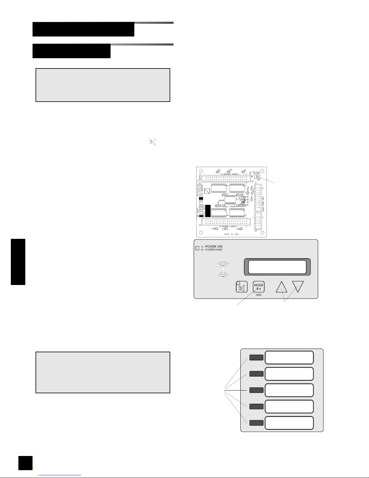
62
6-847718-00 Rev. B00
Operation
Set-Up Procedures (Cont.)
Multiplexer Module
6. Select desired display brightness by
pressing either ! or " buttons. Each
push will increase or decrease
brightness of display. Audible alarm
will chirp one time with each button
press and two times when limit is
reached.
7. Press and release TEST button to
save changes. LEDs will sweep from
top to bottom to indicate end of set-up
sequence.
8. Multiplexer module will return to
monitoring mode.
Setting Audible Alarm Repeat Time and
Display Intensity:
Used to set time interval for reactivation
of audible alarm after alarm MUTE
button has been pressed.
1. Loosen two screws on front of alarm
panel. Hinge open front cover.
2. Locate SETUP button on multiplexer
module circuit board (Figure 43).
3. Press and release SETUP button.
Audible alarm will chirp and
multiplexer module front panel LED
indicators will show current audible
alarm repeat time as shown below:
Indicator Illuminated Repeat Time
None OFF
LED 1 - red 1 Min.
LED 2 - red 5 Min.
LED 3 - red 15 Min.
LED 4 - red 30 Min.
LED 1 - green 1 Hr.
LED 2 - green 2 Hr.
LED 3 - green 8 Hr.
LED 4 - green 12 Hr.
LED 5 - green 24 Hr.
4. Using either ! or " buttons, select
desired audible alarm repeat time.
5 Press and release TEST button on
front of alarm panel. All LEDs will
illuminate.
NOTE:
To comply with the requirements of the City of
New York Department of Buildings; Materials
and Equipment Acceptance Division (M.E.A.),
set audible alarm repeat time to 30 minutes.
NOTE:
Normally, no setup is required for the multiplexer module. The following advanced setup procedures are available.
Multiplexer Module Board
SETUP
button
TEST
button
Up and down
buttons
LED 1
LED 2
LED 3
LED 4
LED 5
Status LEDs
Figure 44: Multiplexer Module LEDs
Figure 43: Multiplexer Programming Buttons
Page 65
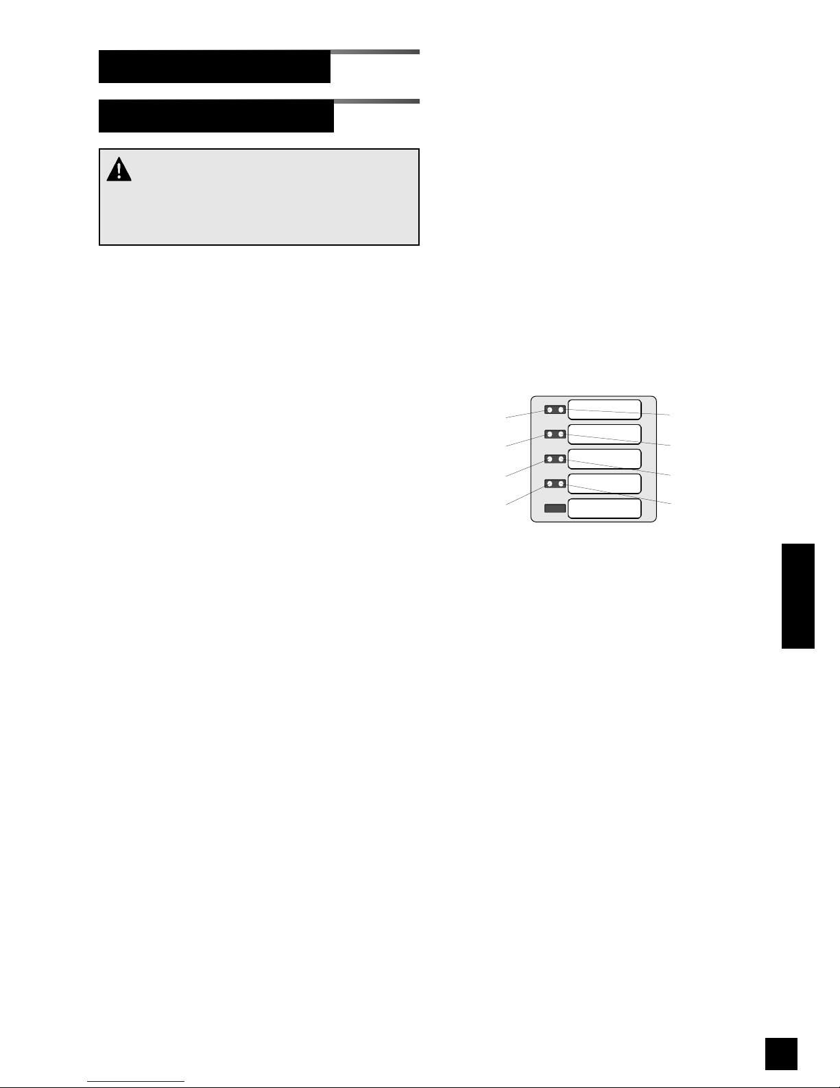
63
6-847718-00 Rev. B00
Operation
LED 1
LED 2
LED 3
LED 4
LED 5
Bit 4 (16)
Bit 0 (1)
Bit 1 (2)
Bit 2 (4)
Bit 3 (8)
Bit 5 (32)
Bit 6 (64)
Bit 7 (128)
Figure 45: Binary data represented by LEDs
Red LEDs
Green LEDs
Set-Up Procedures (Cont.)
Multiplexer Module (Cont.)
Setting Communication Parameters:
Address range is 0 to 255. Factory default
setting is 8.
Network address is shown as a binary
number on specific red and green front
panel LEDs. A numeric value is assigned
to each LED (Figure 45).
For example, if LEDs for bits 0 and 2 were
illuminated, network address would be 5 (1
+ 4 = 5).
1. Press and HOLD set-up button.
Audible alarm will chirp when set-up
button is first pushed and again two
seconds later. Release button after
second audible alarm chirp.
2. Multiplexer module front panel LEDs
will show network address. If no LEDs
are illuminated, address is 0.
3. Using either ! or " buttons, select
desired network address between 0
and 255.
4. Press and release TEST button to save
changes. LEDs will sweep from top to
bottom to indicate end of set-up
sequence.
5. Multiplexer module will return to
monitoring mode.
CAUTION:
Communication parameters are factory set and
should not be changed. These instructions are
provided for programming replacement modules.
Page 66
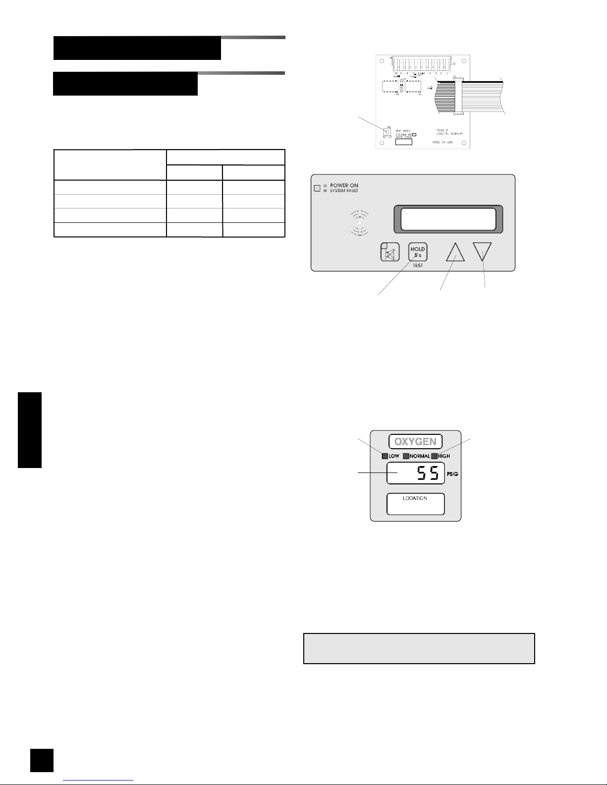
64
6-847718-00 Rev. B00
Operation
Set-Up Procedures (Cont.)
Digital display modules are shipped from
the factory with the following settings:
Gas/Vacuum Alarm Set Point
Service Low High
Pressure (50 psig) 40 psig 60 psig
Pressure (100 psig) 80 psig 120 psig
Nitrogen, Instr. Air 140 psig 190 psig
Vacuum/WAGD 12 in Hg. none
Changing units and alarm set points:
1. Loosen two screws on front of alarm
panel. Hinge open alarm panel’s front
cover.
2. Locate SETUP button on circuit board
of digital display module to be adjusted (Figure 46).
3. Press and release SETUP button.
Audible alarm will chirp and
SS EE TT 11
will
be displayed.
4. Press and release TEST button on
front of alarm panel. Current unit of
measure will be displayed. Select
desired unit of measure by pressing
either ! or " buttons. Available units
of measure are:
KK PP AA
(kPa)
PP SS II
(psig)
II NN KK 99
(in Hg)
NN NN KK 99
(mm Hg)
5. Press and release TEST button. The
LOW indicator will illuminate and
LL OO
will be displayed. After two seconds
current low alarm setting will be
displayed. Select desired low alarm
setting by pressing either ! or "
buttons. Low alarm setting ranges
are:
Digital Display Module Board
SETUP
button
TEST
button
Up and down
buttons
Low alarm
LED
High alarm
LED
Display
Digital Display Module
Figure 47: Digital Display Module
NOTE:
Audible alarm will chirp with each button push.
Figure 46: Digital Display Programming Buttons
Page 67
65
6-847718-00 Rev. B00
Operation
Set-Up Procedures (Cont.)
00
to
11 33 88 00(11 77 22 55
*) (kPa)
00
to
22 00 00(22 55 00
*) (psig)
00
to
33 22
(in Hg)
00
to
88 00 00
(mm Hg)
*N2 and instrument air only
6. Press and release TEST button.
HIGH indicator will illuminate and
KK ,,
will be displayed. After two seconds
current high alarm setting will be
displayed. Select desired high alarm
setting by pressing either ! or "
buttons. High alarm setting ranges
are:
00
to
11 33 88 00(11 77 22 55
*) (kPa)
00
to
22 00 00(22 55 00
*) (psig)
00
to
33 22
or
NN OO NN EE
(in Hg)
00
to
88 00 00
or
NN OO NN EE
(mm Hg)
*N2 and instrument air only
7. Press and release TEST button to
save changes.
DD OO NN EE
will be
displayed for two seconds.
8. Digital display module will return to
monitoring mode.
NOTE:
If module is idle for more than one minute during set-up procedure, module will chirp three
times, return to monitoring mode and will
default to previous settings. No changes to
settings will be saved.
The set-up must be completed and the module
must display
DD OO NN EE
in order for changes to be
saved.
Digital Display Module (Cont.)
Page 68
66
6-847718-00 Rev. B00
Operation
Digital Display Module-Advanced
Two additional levels of “advanced” set-up
features are available.
The first advanced level,
SS EE TT 22
, is used to
adjust communication related parameters.
Changing Communication Parameters
AA DD DD RR
(network address)
A network address uniquely identifies each
digital display module in the alarm panel.
Address range is 00to
22 55 55
.
For TotalAlert 2 alarm panels, this setting is
programmed at the factory when the alarm
panel is assembled and should not be
changed.
BB AA UU DD
(baud rate)
Used to set communication speed. User
choices are
44 88 00 00
or
99 66 00 00
.
Baud rate must be set to
99 66 00 00
. for
TotalAlert 2 alarm panels.
NN DD FF
(network data format)
Defines data word length. Choices are
88
(bits) or
11 66
(bits). NDF must be set to
11 66
for TotalAlert 2 alarm panels.
PP DD FF
(pressure data format)
Defines data word length transmitted to a
slave alarm panel. User choices are
88
(bits) or
11 66
(bits). Factory setting is
11 66
.
Set-Up Procedures (Cont.)
1. Press and HOLD SETUP button for
TWO seconds until
SS EE TT 22
is displayed.
2. Press and release TEST button on
front of alarm panel.
AA DD DD RR
will be
displayed for one second and then
current network address. Select
desired address by pressing ! or "
buttons.
Each module must have a unique
address.
3. Press and release TEST button.
BB AA UU DD
will be displayed for one second
and then current baud rate. Select
desired baud rate by pressing ! or
" buttons.
4. Press and release TEST button.
NN DD FF
will be displayed for one second and
then current network data format.
Select desired data format by
pressing ! or " buttons.
5. Press and release TEST button.
PP DD FF
will be displayed for one second and
then current pressure data format.
Select desired data format by
pressing ! or " buttons.
6. Press and release TEST button to
save changes.
DD OO NN EE
will be
displayed for two seconds.
7. Digital display module will return to
monitoring mode.
NOTE:
If module is idle for more than one minute during set-up procedure, module will chirp three
times, return to monitoring mode and will
default to previous settings. No changes to
settings will be saved.
Set-up must be completed and module must
display
DD OO NN EE
in order for changes to be
saved.
CAUTION:
Communication parameters are factory set and
should not be changed. These instructions are
provided for programming replacement modules.
Page 69

67
6-847718-00 Rev. B00
Operation
Set-Up Procedures (Cont.)
Digital Display Module-Advanced
(Cont.)
The second advanced level,
SS EE TT 33
, is
used to adjust other miscellaneous
parameters as listed below:
Changing Miscellaneous Parameters
SS EE RR UU
(gas service identification)
Used to set digital display module’s gas
service identification for communication
with a digital sensor.
User choices are:
00 22
(oxygen)
NN 22 00
(nitrous oxide)
AA ,, RR
(medical air)
UU AA ((
(vacuum)
NN 22
(nitrogen)
LL AA ,, RR
(lab air)
LL UU AA ((
(lab vacuum)
AA RR 99 NN
(argon)
II AA ,, RR
(instrument air)
UU AA 99 DD
(WAGD)
(( 00 22
(carbon dioxide)
(( -- 00 22
(CO2/O2)
00 22 -- ((
(O2/CO2)
KK EE 00 22
(He/O2)
00 22 KK EE
(O2/He)
KK EE
(Helium)
NN OO NN EE
(none)
OO FF FF SS
(display offset)
Used to adjust digital module’s display.
User choices are 00,11,22,
-- 11
, or
-- 22
.
Factory setting is 00.
RR EE PP TT
(audible alarm repeat)
Used to set time interval for reactivation of
audible alarm after alarm MUTE button
has been pressed.
User choices are:
OO FF FF
11,55, 11 55,33 00
(minutes),
11 HH RR, 88 HH RR, 11 22 HH RR
or
22 44 HH RR
(hour).
Factory setting is
OO FF FF
.
When set to
OO FF FF
, audible alarm will not
reactivate after an active alarm has been
silenced. Any new alarm will reactivate
audible alarm.
II NN TT SS
(display intensity)
Used to adjust digital module’s display
brightness.
Factory setting is maximum intensity.
1. Press and HOLD SETUP button for
FOUR seconds until
SS EE TT 33
is displayed.
2. Press and release TEST button on front
of alarm panel.
SS EE RR UU
will be displayed
for one second and then current gas
service identification. Select desired
gas service by pressing ! or "
buttons.
3. Press and release TEST button.
OO FF F
F SS
will be displayed for one second and
then current display offset. Select
offset by pressing ! or " buttons.
4. Press and release TEST button.
RR EE PP TT
will be displayed for one second and
then current audible alarm repeat time.
Select desired repeat time by pressing
! or " buttons.
5. Press and release TEST button.
II NN TT SS
will be displayed. Select desired
display brightness by pressing ! or "
buttons. Each push will change
brightness of display. Audible alarm will
chirp one time with each push and two
times when limit reached.
6. Press and release TEST button to save
changes.
DD OO NN EE
will be displayed for
two seconds.
Page 70
68
6-847718-00 Rev. B00
Set-Up Procedures (Cont.)
Digital Display Module-Advanced
(Cont.)
7. Digital display module will return to
monitoring mode.
NOTE:
If module is idle for more than one minute during set-up procedure, module will chirp three
times, return to monitoring mode and will default
to previous settings. No changes to settings will
be saved.
Set-up must be completed and module must
display
DD OO NN EE
in order for changes to be saved.
Operation
Page 71
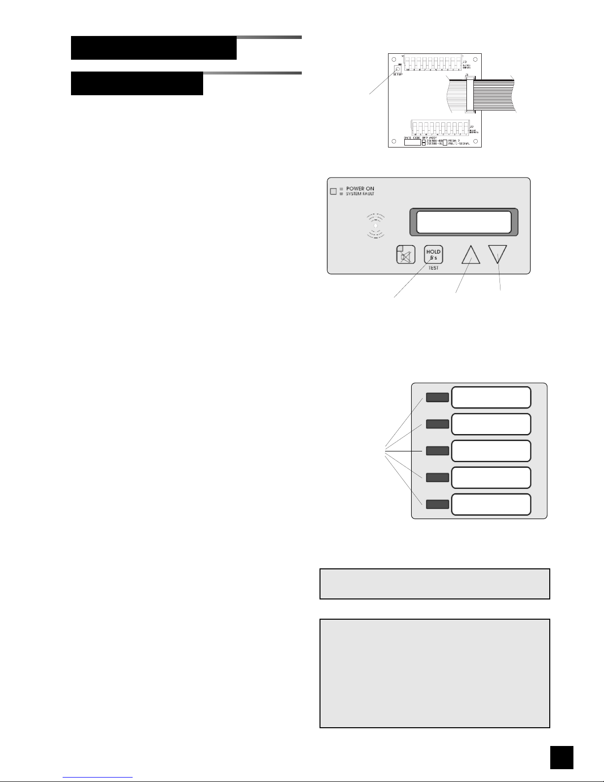
69
6-847718-00 Rev. B00
Set-Up Procedures (Cont.)
Multi-Signal Module
Changing signal options:
1. Loosen two screws on front of alarm
panel. Hinge open front cover.
2. Locate SETUP button on circuit board
of multi-signal module to be adjusted
(Figure 48).
3. Press and release SETUP button.
Audible alarm will chirp and both
green and red indicators for top
location (Signal 1) will illuminate.
4. Using either ! or " buttons, enable
or disable Signal 1 location. When red
indicator is illuminated, location is
ENABLED. Turning off red indicator
disables location. Signal locations can
not be disabled if wired to a closedcontact circuit.
5. Press and release TEST button on
front of alarm panel. Both green and
red indicators for second location
(Signal 2) will be illuminated.
6. Using either ! or " buttons, enable
or disable Signal 2 location. When red
LED is illuminated, location is enabled.
Turning off red LED disables location.
7. Repeat steps 5 and 6 above for
remaining signal locations (Signal 3, 4,
and 5).
8. Press and release TEST button to
save changes. LEDs will sweep from
top to bottom to indicate end of set-up
sequence has been reached.
9. Multi-signal module will return to
monitoring mode.
NOTE:
If module is idle for more than one minute during
set-up procedure, module will chirp three times,
return to monitor mode and will default to previous settings. No changes to settings will be
saved.
Set-up must be completed in order for changes to
be saved.
Multi-Signal Module Board
SETUP
button
NOTE:
Audible alarm will chirp with each button push.
TEST
button
Up and down
buttons
Signal 1
Signal 2
Signal 3
Signal 4
Signal 5
Status LEDs
Figure 49: Multi-Signal Module LEDs
Figure 48: Digital Display Programming Buttons
Page 72
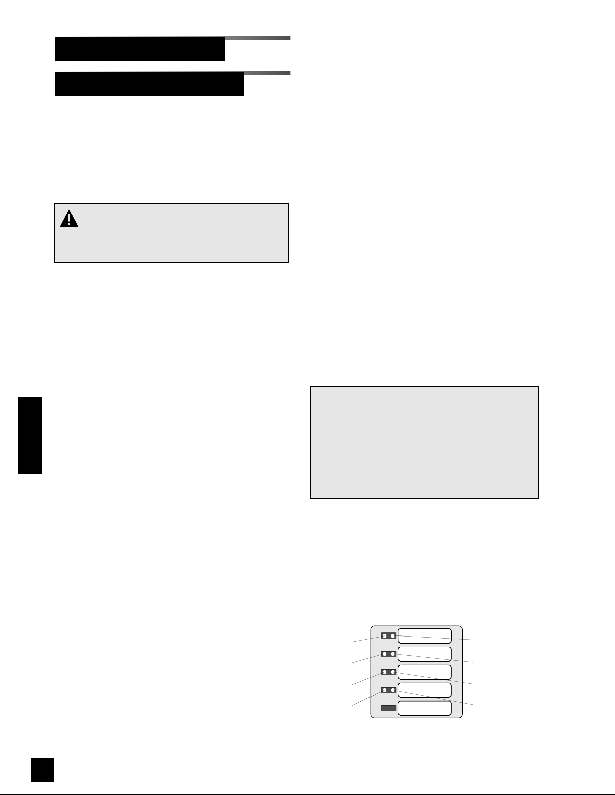
Two additional levels of “advanced” set-up
features are available. The first level is
used to adjust basic communication related
parameters. The second level is used to
adjust alarm repeat time and display
intensity.
Setting Communication Parameters:
A network address uniquely identifies each
alarm module in the alarm panel. Address
range is 0 to 255.
Network address is shown as a binary
number on specific red and green front
panel LEDs. A numeric value is assigned
to each LED (Figure 50)
For example, if LEDs for bits 1 and 2 were
illuminated, network address would be 6 (2
+ 4 = 6).
1. Press and HOLD set-up button.
Audible alarm will chirp when set-up
button is first pushed and again two
seconds later. Release button after
second audible alarm chirp.
2. Multi-signal alarm module front panel
LEDs will show current network
address. If no LEDs are illuminated,
address is 0.
2. Using either ! or " buttons, select
desired network address between 0
and 255.
3. Press and release TEST button on front
of alarm panel. Front panel LEDs (Bit 0
and Bit 4) will show current
communication baud rate. If only Bit 4
LED is illuminated, baud rate is 4800.
If BOTH Bit 0 and Bit 4 LEDs are
illuminated, baud rate is 9600.
Baud rate must be set to 9600 for
TotalAlert 2 alarm panels.
4. Using either ! or " buttons, select
desired baud rate (4800 or 9600).
5 Press and release TEST button on front
of alarm panel. Front panel LEDs (Bit 1
and Bit 5) will show current
communication data format. If only Bit
5 LED is illuminated, data format is 8bit word length (factory setting). If
BOTH Bit 1 and Bit 5 LEDs are
illuminated, data format is 16-bit word
length.
6. Using either ! or " buttons, select
desired data format (8-bit or 16-bit).
7. Press and release TEST button to save
changes. LEDs will sweep from top to
bottom to indicate end of set-up
sequence has been reached.
8. Multi-signal module will return to
monitoring mode.
NOTE:
If module is idle for more than one minute during
set-up procedure, module will chirp three times,
return to monitoring mode and will default to previous settings. No changes to settings will be
saved.
Set-up must be completed in order for changes
to be saved.
70
6-847718-00 Rev. B00
Multi-Signal Module-Advanced
Set-Up Procedures (Cont.)
Operation
SIGNAL 1
SIGNAL 2
SIGNAL 3
SIGNAL 4
SIGNAL 5
Bit 4 (16)
Bit 0 (1)
Bit 1 (2)
Bit 2 (4)
Bit 3 (8)
Bit 5 (32)
Bit 6 (64)
Bit 7 (128)
Figure 50: Binary data represented by LEDs
Red LEDs
Green LEDs
CAUTION:
Communication parameters are factory set and
should not be changed.
Page 73
71
6-847718-00 Rev. B00
Operation
Set-Up Procedures (Cont.)
Multi-Signal Module-Advanced (Cont.)
Setting Audible Alarm Repeat Time and
Display Intensity:
Used to set time interval for reactivation of
audible alarm after alarm MUTE button
has been pressed.
1. Press and HOLD SETUP button.
Audible alarm will chirp when SETUP
button is first pushed, again after two
seconds and a third time after four
seconds. Release button after third
audible alarm chirp. Multi-signal module
front panel LED indicators will show
current audible alarm repeat time as
shown below:
Indicator Illuminated Repeat Time
None OFF
Signal 1 - red 1 Min.
Signal 2 - red 5 Min.
Signal 3 - red 15 Min.
Signal 4 - red 30 Min.
Signal 1 - green 1 Hr.
Signal 2 - green 2 Hr.
Signal 3 - green 8 Hr.
Signal 4 - green 12 Hr.
Signal 5 - green 24 Hr.
2. Using either ! or " buttons, select
desired audible alarm repeat time.
3 Press and release TEST button on front
of alarm panel. All LED indicators will
illuminate.
4. Select desired display brightness by
pressing either ! or " buttons. Each
push will increase or decrease
brightness of display. Audible alarm will
chirp one time with each button push
and two times when limit is reached.
NOTE:
To comply with the requirements of the City of
New York Department of Buildings; Materials
and Equipment Acceptance Division (M.E.A.),
set audible alarm repeat time to 30 minutes.
5. Press and release TEST button to save
changes. LEDs will sweep from top to
bottom to indicate end of set-up
sequence.
6. Multi-signal module will return to
monitoring mode.
NOTE:
If module is idle for more than one minute during set-up procedure, module will chirp three
times, return to monitoring mode and will default
to previous settings. No changes to settings will
be saved.
Set-up must be completed in order for changes
to be saved.
Page 74
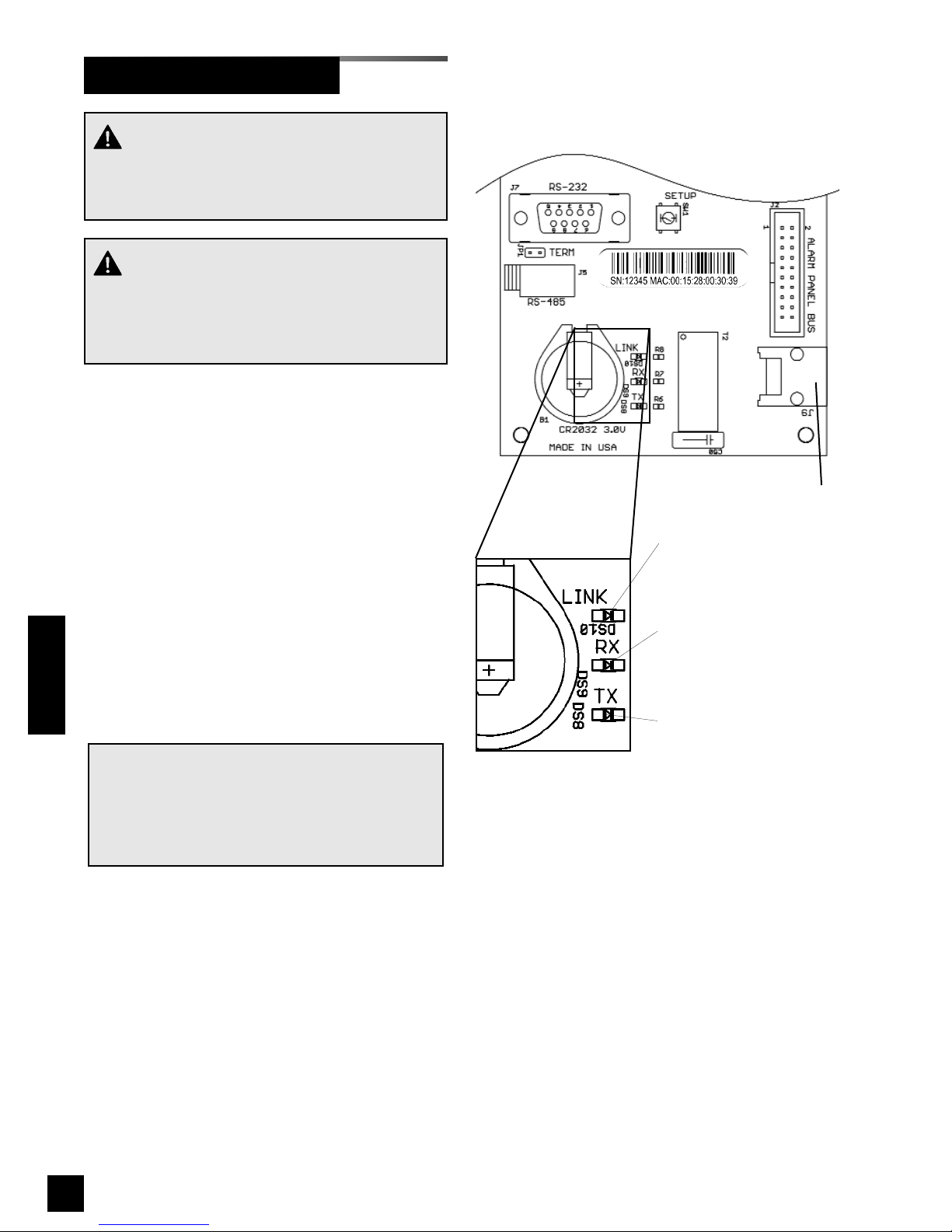
72
6-847718-00 Rev. B00
Equipment Required
• PC with an Ethernet connection
• PC with a web browser, such as
Microsoft Internet Explorer
• Category 5 Ethernet cable (10BaseT)
(if connecting through a switch or hub)
• Category 5 Ethernet crossover cable
(if connecting PC directly to alarm)
Physical Connection
1a.Connect each device to an Ethernet
switch or hub using a Cat-5 Ethernet
cable (Figures 53-55).
1b.For direct connection to a PC without
using a hub or switch, connect the
device to the PC using a Cat-5 Ethernet
crossover cable (Figure 52).
2. Verify the green LINK LED on the
annunciator module illuminates
(Figure 51).
NOTE:
It is best to use a switch instead of a hub
because the devices communicate at 10 Mbits/s.
A switch also improves network performance and
keeps unnecessary traffic from being routed to
the alarm.
CAUTION:
Have the facility’s Information Systems personnel
set up the network interface. If the set up is done
improperly, equipment may not perform properly.
CAUTION:
The information systems personnel should be
notified before changing any of the network
settings. Changing the settings could keep the
equipment from working properly.
Link LED
Indicates physical
connection
10BaseT Ethernet
Connector
Receive LED
Indicates device is
receiving packets
Transmit LED
Indicates device is
transmitting packets
Figure 51 Ethernet status LEDs
Set-Up Network Interface
Operation
Page 75
73
6-847718-00 Rev. B00
Operation
Addressing using DHCP (factory
default)
1. Upon power-up, the device will search
for a DHCP server. If a DHCP server is
found, IP Address, subnet mask and
gateway are automatically obtained.
2. If a DHCP server is not found, the fixed
IP configuration will be used:
3. The device will check for a DHCP
server every 3 minutes. If a DHCP
server is found, fixed IP configuration
will be discarded and the DHCP
provided IP configuration will be used.
Addressing using fixed IP address
1. Upon power-up, the device will
immediately begin using the fixed IP
configuration.
Connecting to the alarm
1. Start a web browser such as Microsoft
Internet Explorer.
2a.Enter the Device Name in the browser’s
address bar.
Device Name:
TA2_XXXXX where XXXXX is the
device serial number.
2b.Enter the Device’s IP address in the
browser’s address bar:
Example: http://192.168.1.100
NOTE:
To learn the IP address of a master or combo
alarm, press and hold the TEST button on the
front panel for 5 seconds. The IP address will be
shown on the VFD.
Factory default fixed IP Configuration
IP Address: 192.168.1.100
Gateway: 192.168.1.1
Subnet Mask: 255.255.255.0
Set-Up Network Interface (Cont.)
NOTE:
Browsers can locate devices in the following three
ways:
1. IP Address
Example: http://192.168.1.100
2. Local name lookup using NetBIOS name
service
Example: http://TA2_12345
This method works on a LAN if NetBIOS
name lookup is enabled.
3. DNS name lookup
Example:
http://www.yourfacility.com/TA2_12345
This method requires the device to be
enrolled in the facility’s DNS server.
Page 76
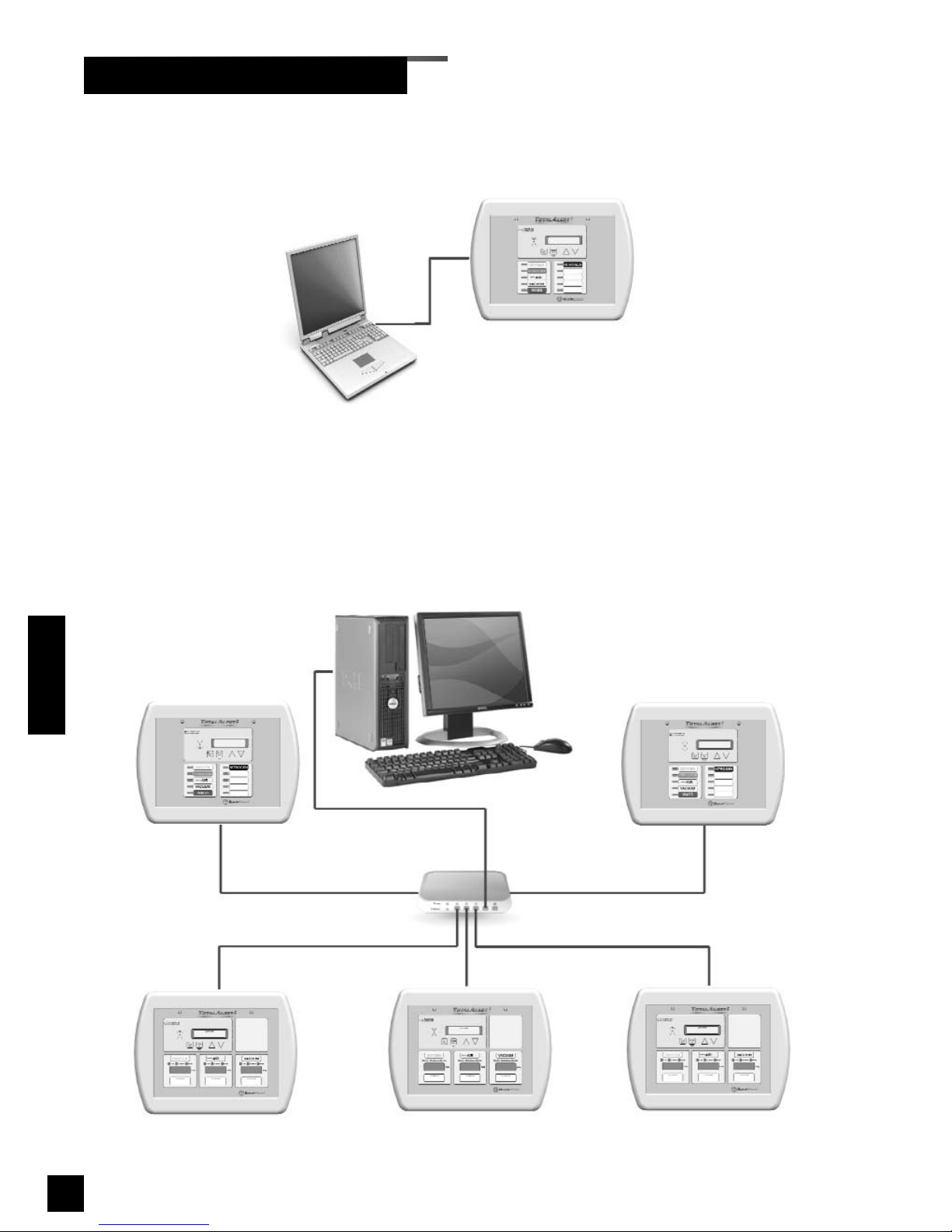
74
6-847718-00 Rev. B00
Figure 53 Simple Unmanaged Network
Figure 52 Direct Connection
Set-Up Network Interface (Cont.)
Operation
Hub or Switch
Computer
Computer
Page 77
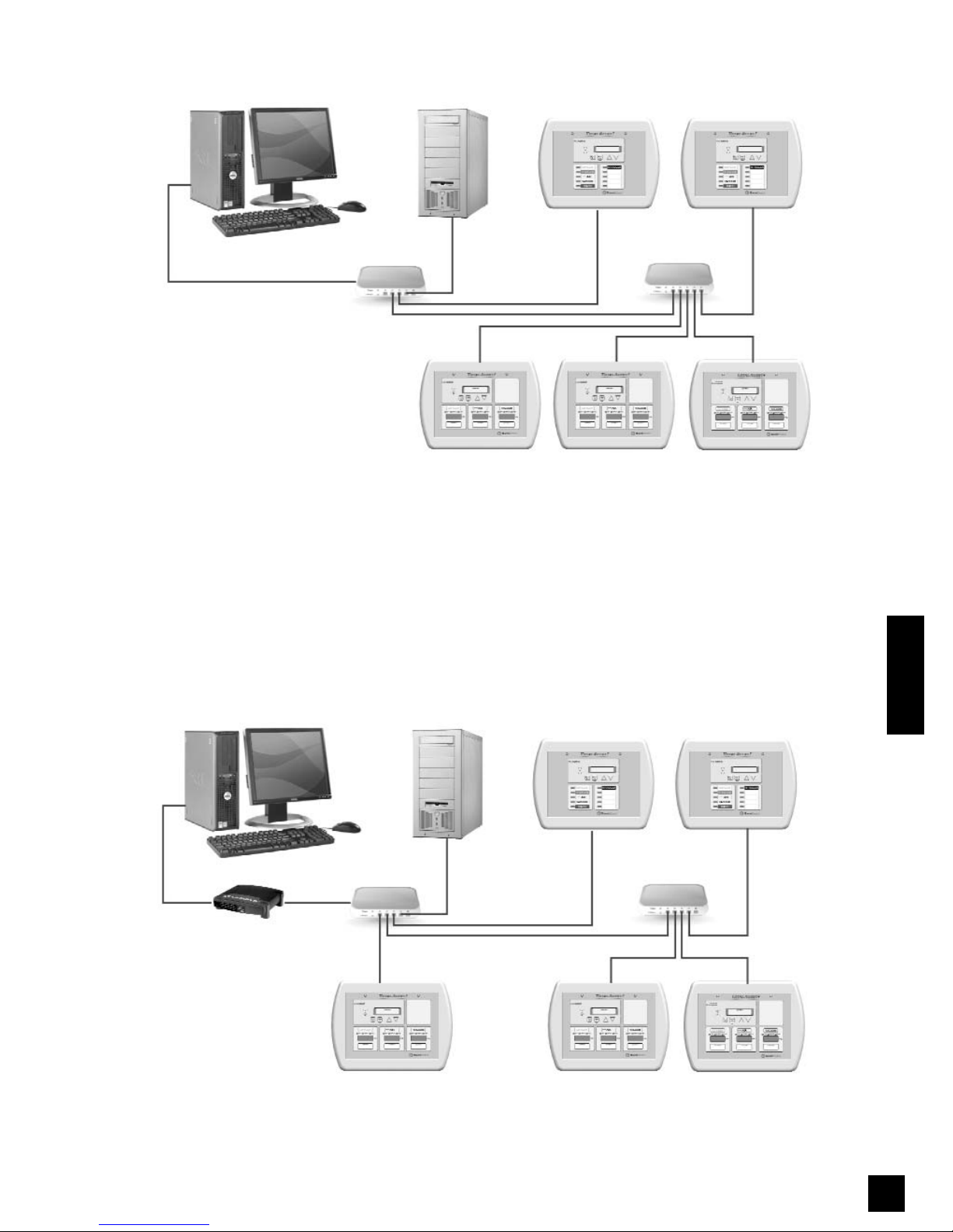
75
6-847718-00 Rev. B00
Operation
Figure 55 Complex Managed Network
Hub or Switch
Computer
Hub or Switch
Network Server
Hub or Switch
Hub or Switch
Computer
Network Server
Network Router
Figure 54 Simple Managed Network
Page 78
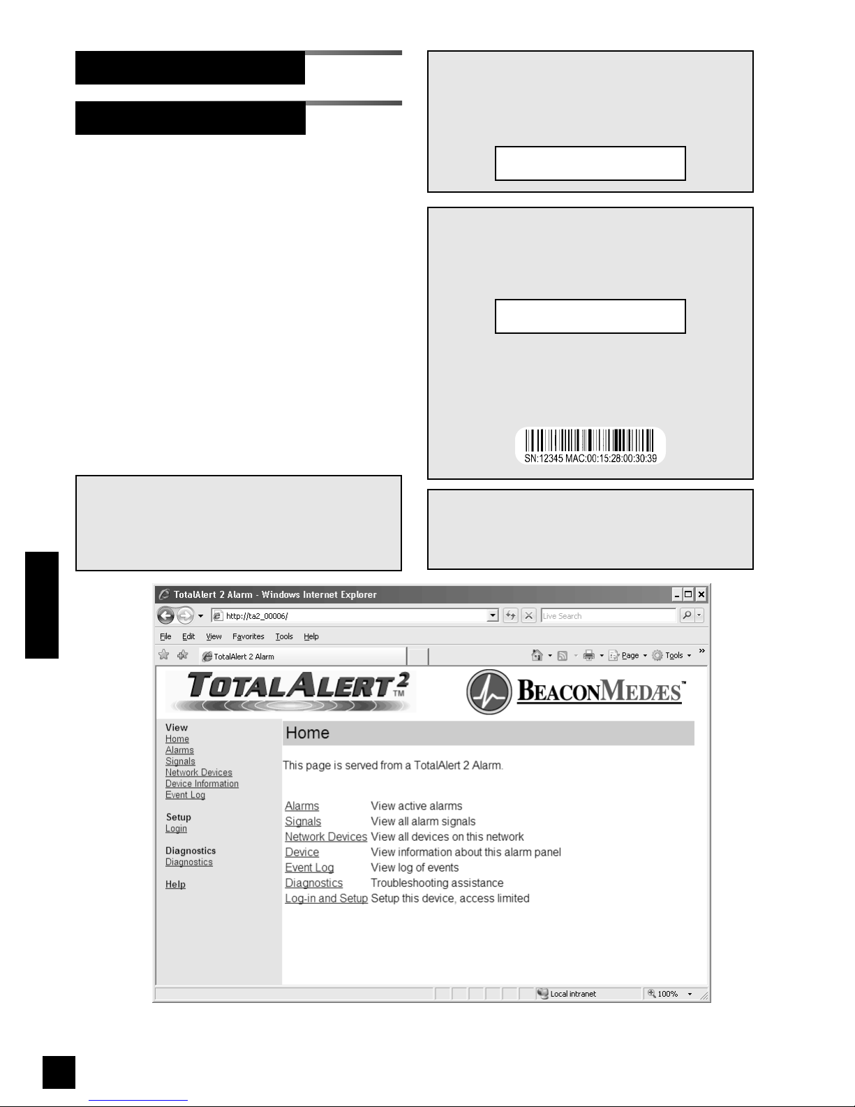
76
6-847718-00 Rev. B00
Operation
1. Start a web browser such as Microsoft
Internet Explorer.
2a.Enter the Device Name in the browser’s
address bar.
Device Name:
TA2_XXXXX where XXXXX is the
device serial number.
2b.Enter the Device’s IP address in the
browser’s address bar:
Example: http://10.10.5.10
3. After you enter the device name or IP
address, the alarm’s home page will be
displayed (Figure 56).
Accessing the Web Page
Set-Up Using Web Pages
NOTE:
To learn the IP address of a master or combo
alarm, press and hold the TEST button on the
front panel for 5 seconds. The IP address will be
shown on the VFD.
NOTE:
To learn the serial number of the alarm, cycle the
power on the alarm panel. The serial number will
be shown on the VFD during the bootup
sequence:
The serial number can also be found on a label
inside the alarm panel. Open the front panel and
locate the bar code label on the annunciator
module.
Version: 1.0.0
SN 12345
NOTE:
To learn the name of a master or combo alarm,
cycle the power on the alarm panel. The name
will be shown on the VFD during the bootup
sequence:
Browse at: http://
TA2_12345
Figure 56: Typical alarm panel home page
NOTE:
If you rename the alarm panel, you can still use
the factory programmed device name to access
the alarm home page.
Page 79
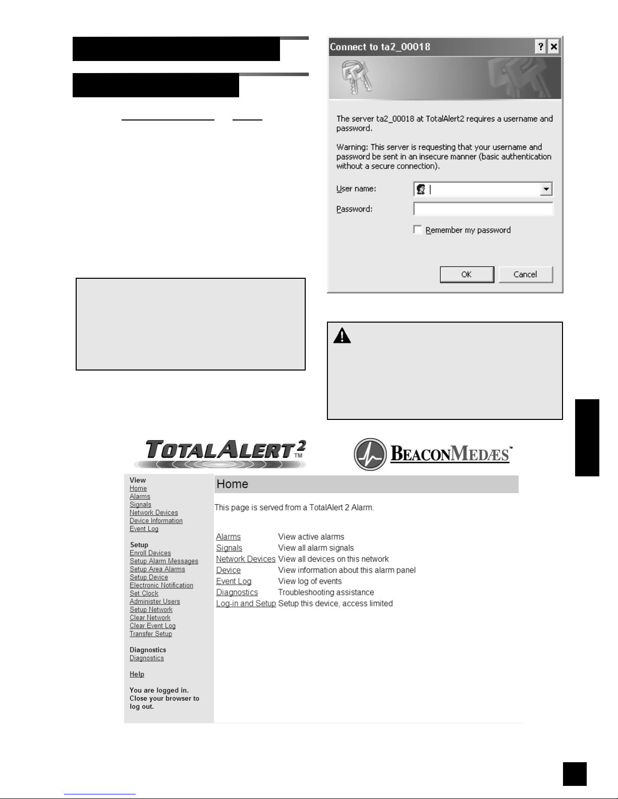
77
6-847718-00 Rev. B00
Operation
1. Click Log in and Setup or Login on the
left pane.
2. The web browser will request a
username and password (Figure 57).
3. The factory defaults are:
Username: new
Password: new
4. The left sidebar will now contain the
setup links (Figure 58)
NOTE:
Logging in applies only to the computer on
which the login occurs. If more than one PC is
being used to access the alarm web pages,
each one must be logged in individually. The
computer stays logged in until the user closes
the browser.
Login in to Setup Pages
Set-Up Using Web Pages (Cont.)
Figure 58: Logged in
WARNING:
Change the factory programmed password after
the first time you log in. Otherwise, inappropriate
personnel may change settings which could
endanger patient welfare. Refer to Administer
Users on page 91.
Figure 57: Login Dialog
Page 80
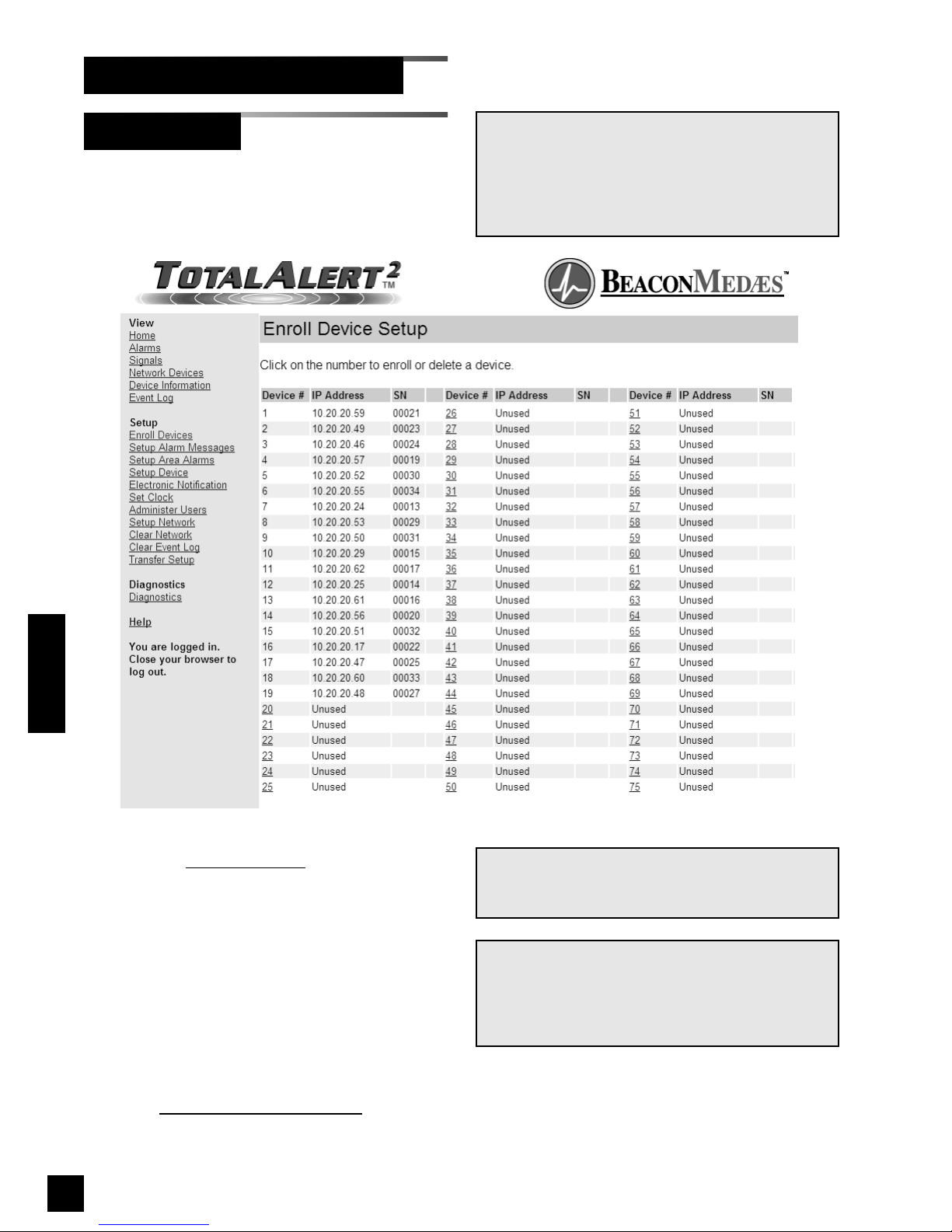
78
6-847718-00 Rev. B00
Operation
Each TotalAlert 2 alarm panel keeps a list
of up to 75 other devices on the medical
gas network.
1. Click on Enroll Devices
to access the
Enroll Devices Setup page (Figure 59).
2. Click on an unused Device # link to
enroll a new device.
3. Enter the device IP address and Device
Serial Number then click Submit
(Figure 60).
4. The Enroll/Delete Device Complete
page will be displayed (Figure 61).
5. Click Return to Enroll Devices
to return
the the Enroll Device Setup page.
Enroll Devices
Set-Up Using Web Pages (Cont.)
Figure 59: Enroll Device Setup
NOTE:
The factory default settings will cause all devices
on the same subnet to be automatically
discovered. Enroll Devices is only necessary if
the alarm network is spread across multiple
subnets.
NOTE:
Device # links are disabled for automatically
enrolled devices.
NOTE:
Fixed IP addresses should be used for manually
enrolled devices. If a manually enrolled device’s
IP address changed, the entry in the device list is
NOT automatically updated.
Page 81
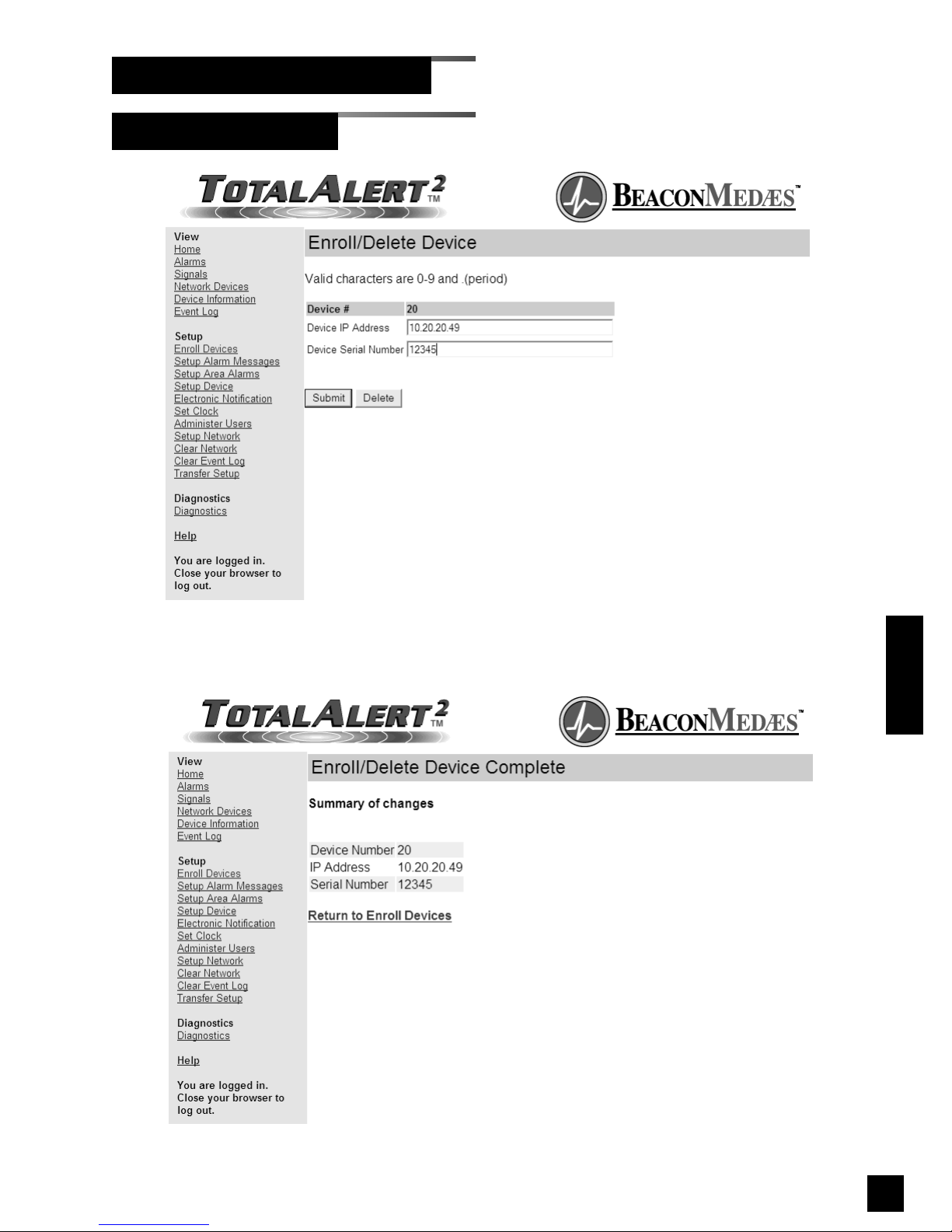
79
6-847718-00 Rev. B00
Operation
Enroll Devices (Cont.)
Set-Up Using Web Pages (Cont.)
Figure 61: Enroll/Delete Device Complete
Figure 60: Enroll/Delete Device
Page 82
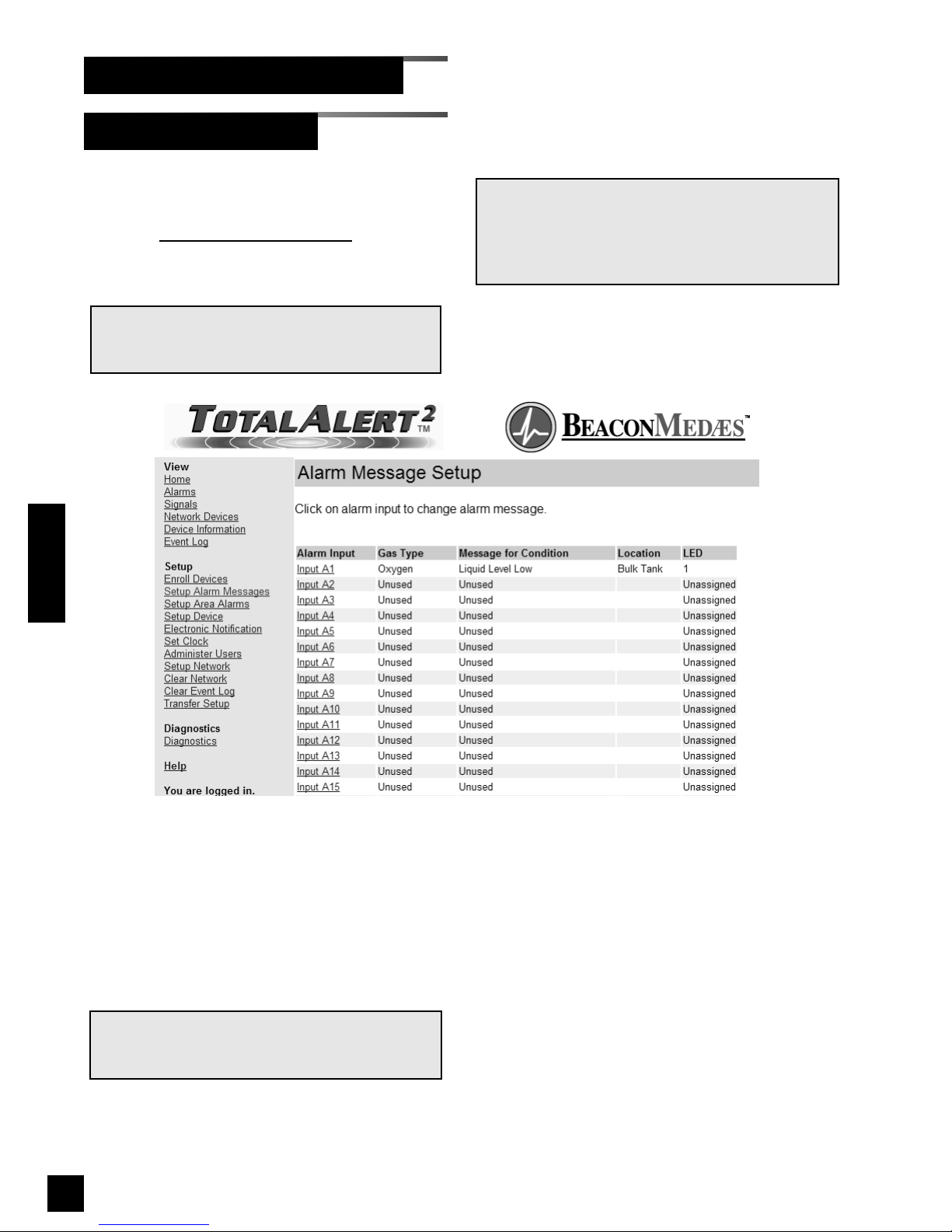
80
6-847718-00 Rev. B00
Setup Alarm Messages
Set-Up Using Web Pages (Cont.)
This setup page is used to configure
switched alarm signals.
1. Click Setup Alarm Messages to access
the Alarm Message Setup page
(Figure 62).
2. Click on the Alarm Input link for the
signal to set up.
3. The Signal Setup - Step 1 page will be
displayed (Figure 63).
4. Select the gas type from the drop-down
menu then click Next.
NOTE:
If a custom gas type is required, select Custom
from the Gas Type drop-down menu.
NOTE:
Before setting up signals, fill out Master Alarm
Signal Input Data table on page 138.
Figure 62: Alarm Message Setup
NOTE:
These settings can be transferred from one
TotalAlert 2 master or combo alarms to another
master or combo alarm. Refer to Transfer Setup
on page 98.
Operation
Page 83
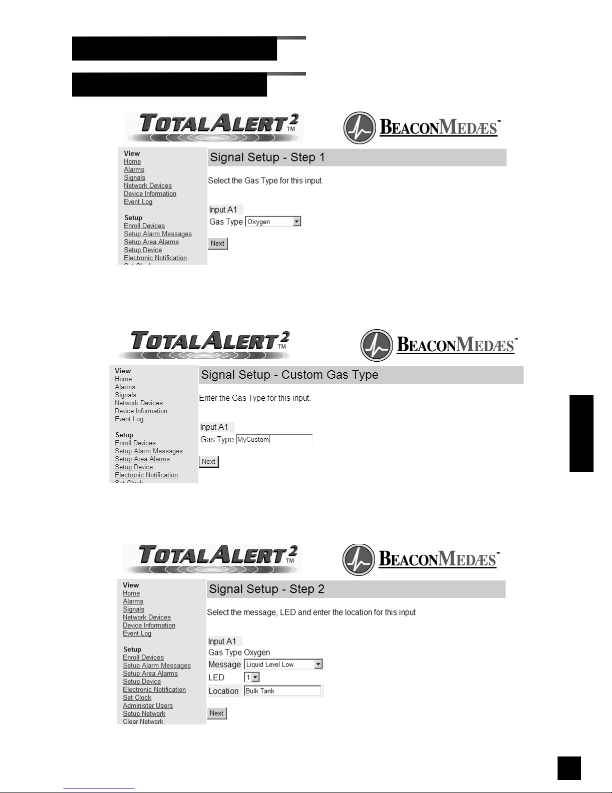
81
6-847718-00 Rev. B00
Setup Alarm Messages (Cont.)
Set-Up Using Web Pages (Cont.)
Operation
Figure 65: Signal Setup - Step 2
Figure 64: Signal Setup - Custom Gas Type
Figure 63: Signal Setup - Step 1
Page 84
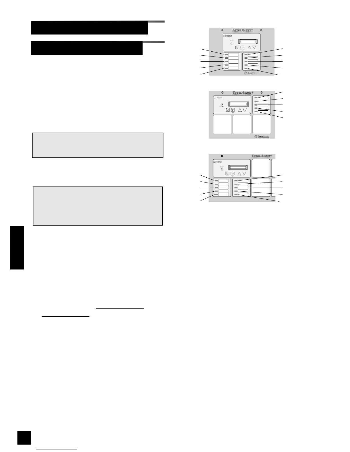
82
6-847718-00 Rev. B00
Draft 29 June 2007
5. If Custom gas type was selected, enter
the custom gas type and click next
(Figure 64).
6. The Signal Setup - Step 2 page will be
displayed (Figure 65).
7. Select the Message for the alarm input
from the drop-down menu.
8. Select the LED number for the alarm
input (Refer to Figure 66).
9. Enter the Location then click Next.
10.If Custom Message was selected, enter
the custom message and click Next
(Figure 67).
11. The Signal setup Summary page will be
displayed (Figure 68).
12.To return to the Alarm Message Setup
page click on the Return to
Alarm
Message Setup link.
NOTE:
Only one type of gas can be assigned to each
LED. After an LED has been assigned to a type
of gas, that LED number is available only for
that particular type of gas.
NOTE:
If a custom message is required, select Custom
Message from the Message drop-down menu.
Setup Alarm Messages (Cont.)
Set-Up Using Web Pages (Cont.)
Figure 66: LED Numbering
1
2
3
4
5
6
7
8
9
10
1
2
3
4
5
1
2
3
4
5
6
7
8
9
10
Master Alarm
Small Combo Alarm
Large Combo Alarm
Operation
Page 85
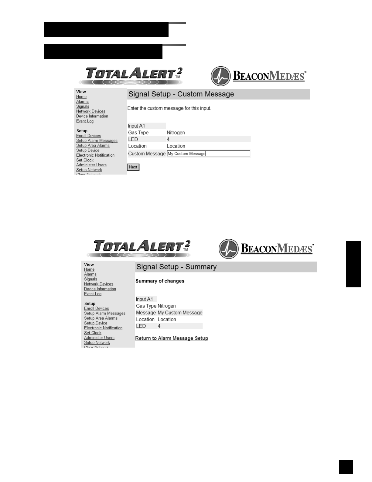
83
6-847718-00 Rev. B00
Setup Alarm Messages (Cont.)
Set-Up Using Web Pages (Cont.)
Figure 68: Signal Setup - Summary
Operation
Figure 67: Signal Setup - Custom Message
Page 86
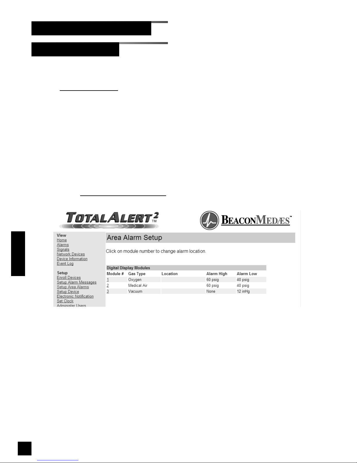
84
6-847718-00 Rev. B00
Setup Area Alarms
Set-Up Using Web Pages (Cont.)
Operation
This setup page is used to configure area
alarm locations.
1. Click Setup Area Alarms to access the
Area Alarm Setup page (Figure 69).
2. Click on the Module # link for the digital
display module to set up.
3. The Area Alarm Setup - Step 1 page
will be displayed (Figure 70).
4. Enter the location then click Next.
5. The Area Alarm Setup - Summary page
will be displayed (Figure 71).
6. To return to the Area Alarm Setup page
click on the Return to
Area Alarm Setup
link.
Figure 69: Area Alarm Setup
Page 87
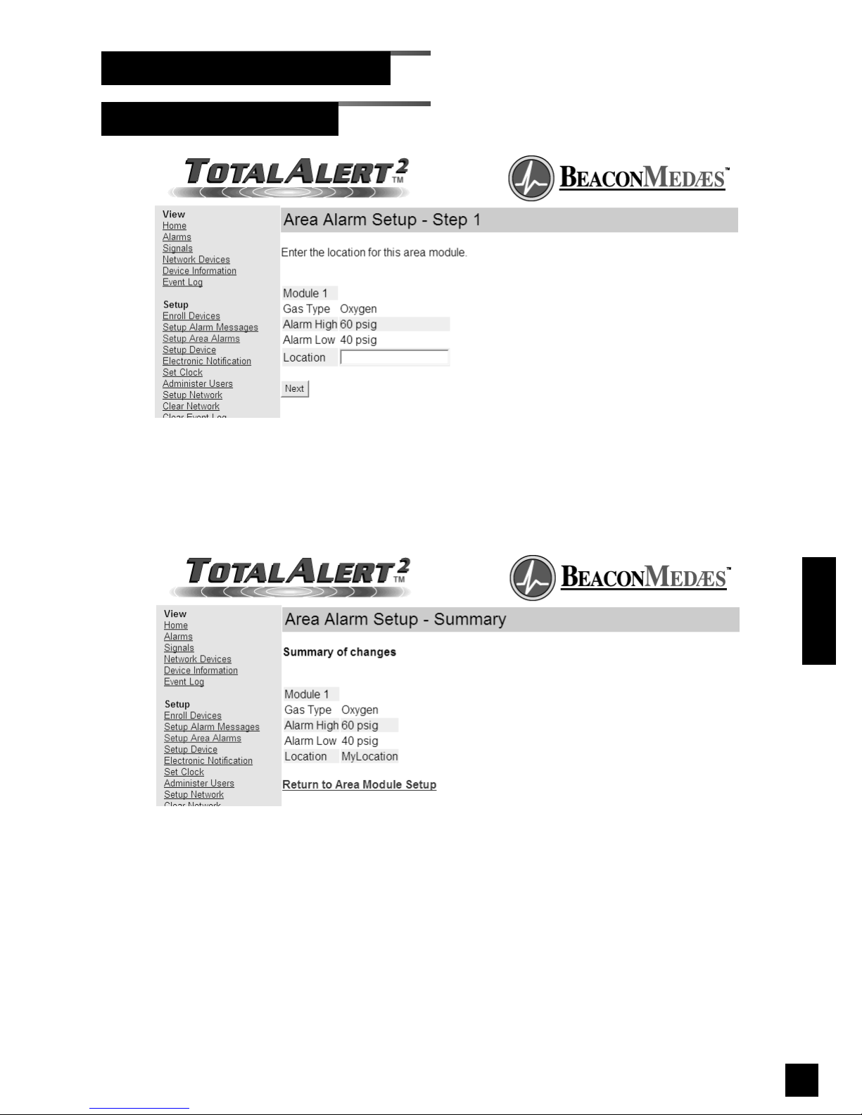
85
6-847718-00 Rev. B00
Setup Area Alarms (Cont.)
Set-Up Using Web Pages (Cont.)
Figure 71: Area Alarm Setup - Summary
Operation
Figure 70: Area Alarm Setup - Step 1
Page 88

86
6-847718-00 Rev. B00
Operation
Setup Device
Set-Up Using Web Pages (Cont.)
This setup page is used to configure alarm
panel name, location, N2 address, facility
description and contact information.
1. Click Setup Device
to access the Setup
Device page (Figure 72).
2. Enter the new device name.
To access the web pages by using the
name you have given it, NetBIOS
Name Service over TCP/IP must be
enabled on your computer (See Set-Up
Network Interface on page 72).
• Without the NetBIOS Name Service
enabled, the device must be
accessed by using its IP address.
• To learn a master or combo alarm’s
IP address, press and hold the
TEST button for 5s.
3. Enter the Location.
4. If the device will be connected to a
Johnson Controls Metasys® building
automation system, select the N2
address.
5. Enter the Facility Description.
6. Enter the Contact Information.
7. Click the Submit button.
8. The Device Setup Accepted page will
be displayed (Figure 73).
NOTE:
The information in these fields identify the alarm
panel that generated an alarm or an event. This
information is displayed on the event log and on
electronic notification messages.
Page 89
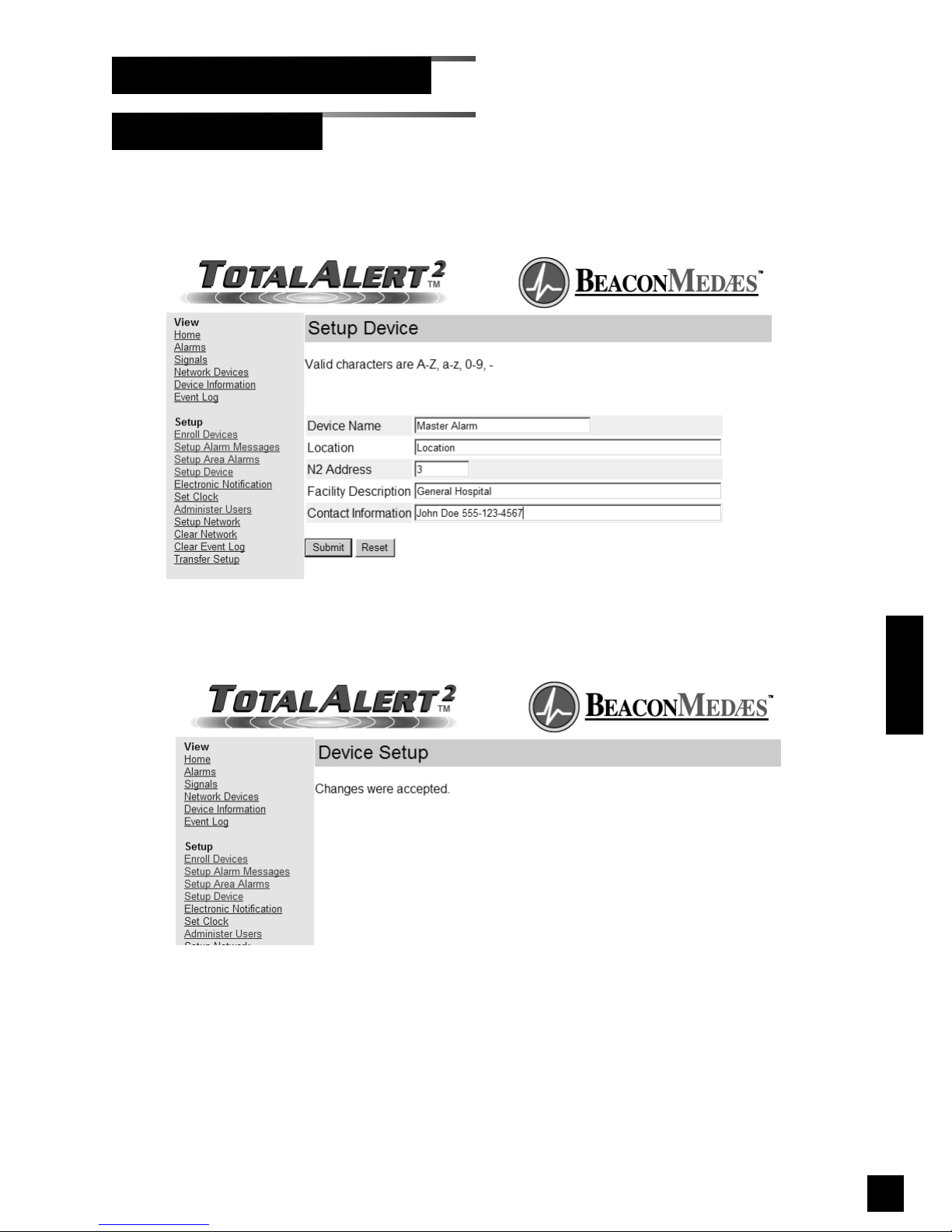
87
6-847718-00 Rev. B00
Operation
Figure 73: Device Setup Accepted
Figure 72: Setup Device
Setup Device (Cont.)
Set-Up Using Web Pages (Cont.)
Page 90
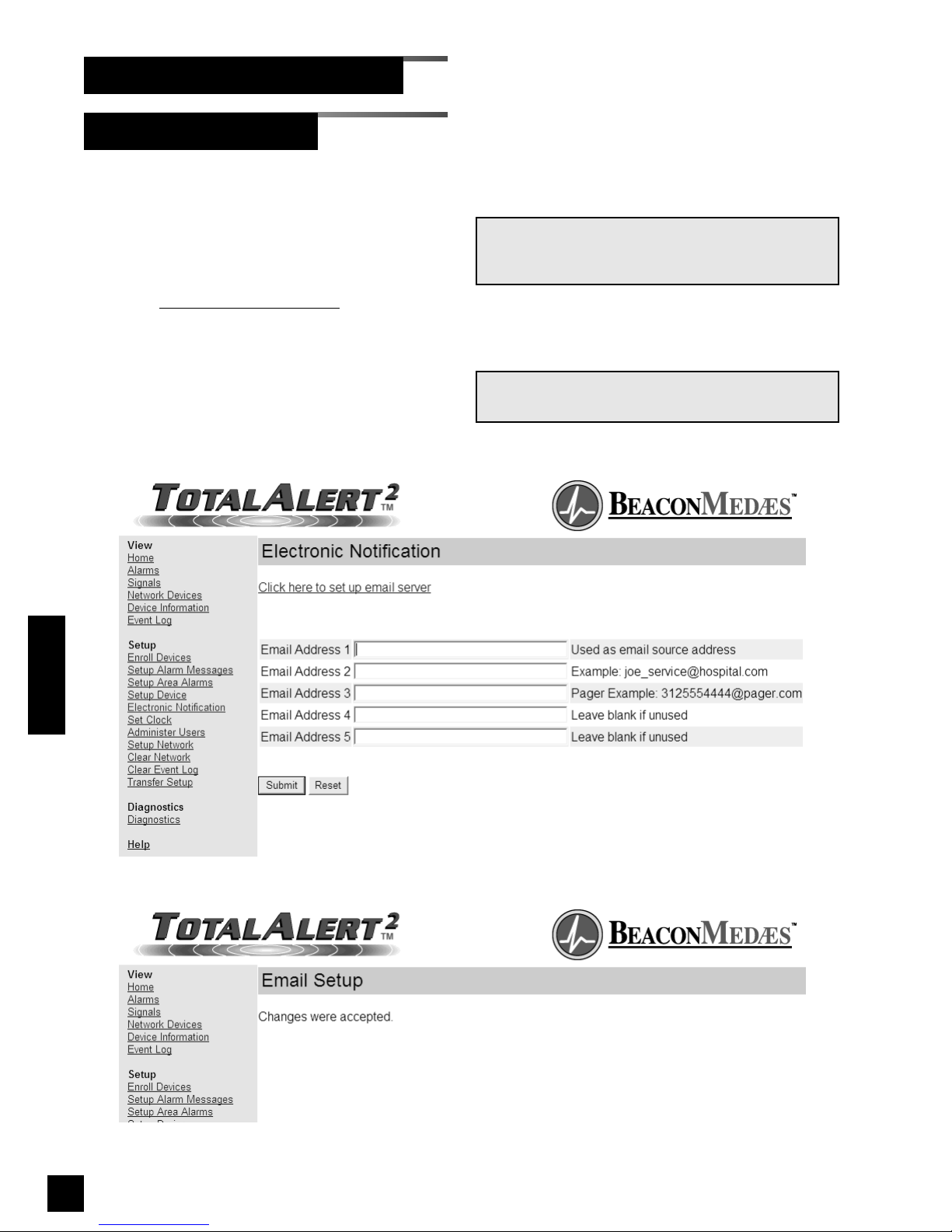
88
6-847718-00 Rev. B00
Electronic Notification
Set-Up Using Web Pages (Cont.)
This setup page is used to configure electronic notification (email, pager, phone text
message). The device acts as an SMTP
client. An SMTP server is required for
electronic notification to function.
1. Click Electronic Notification
to access
the Electronic notification page
(Figure 74).
2. Enter up to five email addresses then
click Submit.
3. The Email Setup Accepted page will be
displayed (Figure 75).
NOTE:
Email address 1 is also used as the email sender.
NOTE:
Refer to your mobile device provider for text
message email address format.
Figure 75: Email Setup Accepted
Operation
Figure 74: Electronic Notification
Page 91
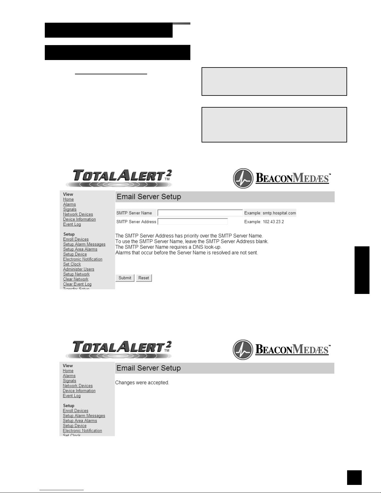
89
6-847718-00 Rev. B00
Electronic Notification - Server Setup
Set-Up Using Web Pages (Cont.)
1. Click Electronic Notification to access
the Electronic notification page
(Figure 74).
2. Click on the link to set up email server
(Figure 76).
3. Enter the SMTP server name or IP
address then click Submit.
4. The Email Server Setup Accepted page
will be displayed (Figure 77).
NOTE:
Obtain the SMTP server name or IP address from
the facility’s Information Systems department.
Figure 77: Email Server Setup Accepted
NOTE:
SMTP Server Address has priority over the SMTP
Server Name. To use the SMTP Server Name,
leave the SMTP Server Address blank.
Operation
Figure 76: Email Server Setup
Page 92
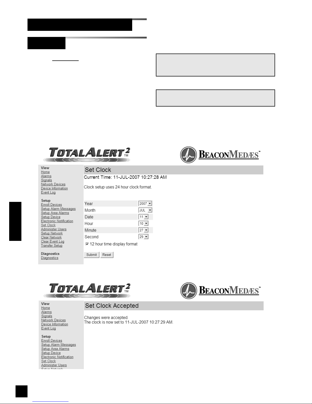
90
6-847718-00 Rev. B00
Set Clock
Set-Up Using Web Pages (Cont.)
1. Click Set Clock to access the Set Clock
page (Figure 78).
2. Select the current time and date from
the drop-down menus.
3. Click the check box if time information
should be displayed in 12 hour format.
4. Click Submit.
5. The Set Clock Accepted page will be
displayed (Figure 79).
NOTE:
Clock setup uses 24 hour clock format.
Figure 79: Set Clock Accepted
NOTE:
The clock is used to date/time stamp web pages
and event log entries.
Operation
Figure 78: Set Clock
Page 93
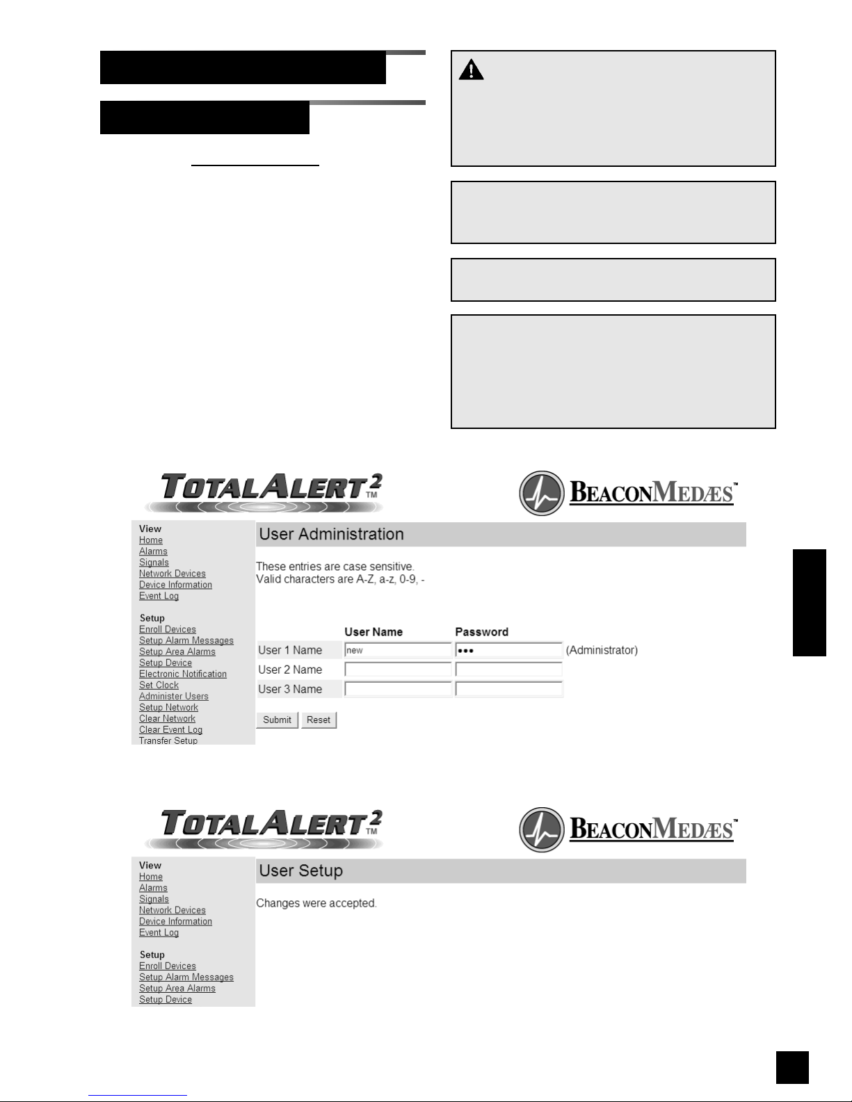
91
6-847718-00 Rev. B00
1. Click on Administer Users to access the
User Administration page (Figure 80).
2. Enter user names and passwords then
click Submit.
3. The User Setup Accepted page will be
displayed (Figure 81).
Administer Users
Set-Up Using Web Pages (Cont.)
WARNING:
Change the factory programmed password after
the first time you log in. Otherwise, inappropriate
personnel may change settings which could
endanger patient welfare.
NOTE:
For security reasons, only User 1 has access to
change user names and passwords.
NOTE:
User names and passwords are case sensitive.
NOTE:
If you forget your username or password, they
can be reset to factory defaults. For master and
combo alarms, refer to Reset Users on page 59.
For area alarms, refer to Reset Users and IP
Configuration on page 61.
Figure 81: User Setup Accepted
Operation
Figure 80: User Administration
Page 94
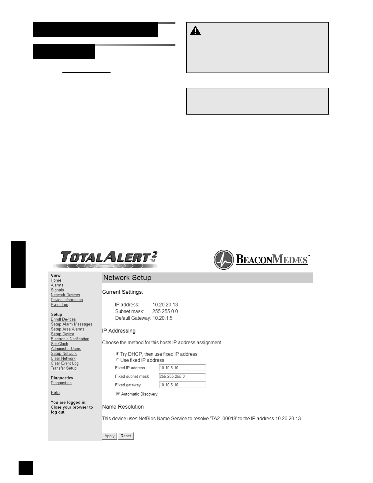
92
6-847718-00 Rev. B00
Setup Network
Set-Up Using Web Pages (Cont.)
1. Click Setup Network to access the
Network Setup page (Figure 82).
The current IP configuration is shown
under Current Settings.
2. Select the IP Addressing mode.
3. If Use fixed IP address is selected,
enter the Fixed IP address, Fixed
subnet mask and Fixed gateway.
4. To disable automatic discovery
broadcasts, uncheck the Automatic
Discovery check box.
5. Click Apply to save the new settings.
6. The Network Setup Accepted page will
be displayed (Figure 83).
Figure 82: Network Setup
Operation
NOTE:
To learn more about the network settings, refer to
Set up Network Interface on page 72.
CAUTION:
The Information Systems personnel should be
notified before changing any of the network settings. Changing the settings could keep the
equipment from working properly.
Page 95
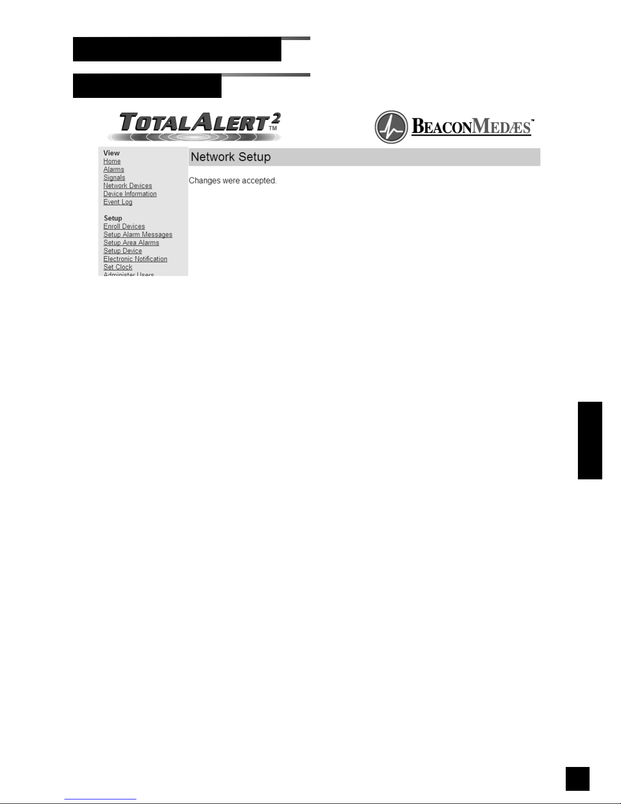
93
6-847718-00 Rev. B00
Setup Network (Cont.)
Set-Up Using Web Pages (Cont.)
Operation
Figure 83: Network Setup Accepted
Page 96
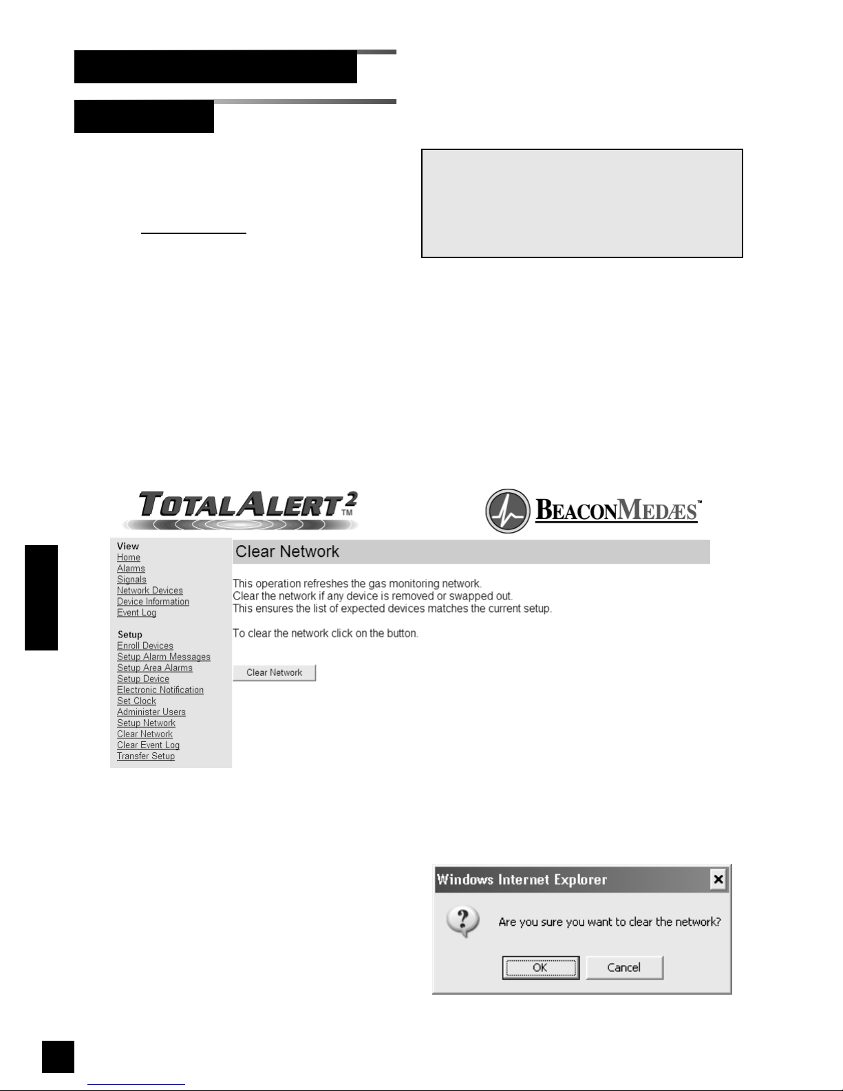
Clear Network clears and refreshes the
device list memory for all devices on the
alarm network.
1. Click Clear Network
to access the Clear
Network page (Figure 84).
2. Click Clear Network.
3. The confirm clear network dialog will be
displayed (Figure 85).
4. Click OK to clear the network.
5. The Clear Network Accepted page will
display (Figure 86)
94
6-847718-00 Rev. B00
Clear Network
Set-Up Using Web Pages (Cont.)
Operation
NOTE:
Clear network only refreshes devices on the same
subnet as the device that issued the clear
network command.
Manually enrolled devices are not refreshed by
clear network.
Figure 85: Confirm Clear Network
Figure 84: Clear Network
Page 97
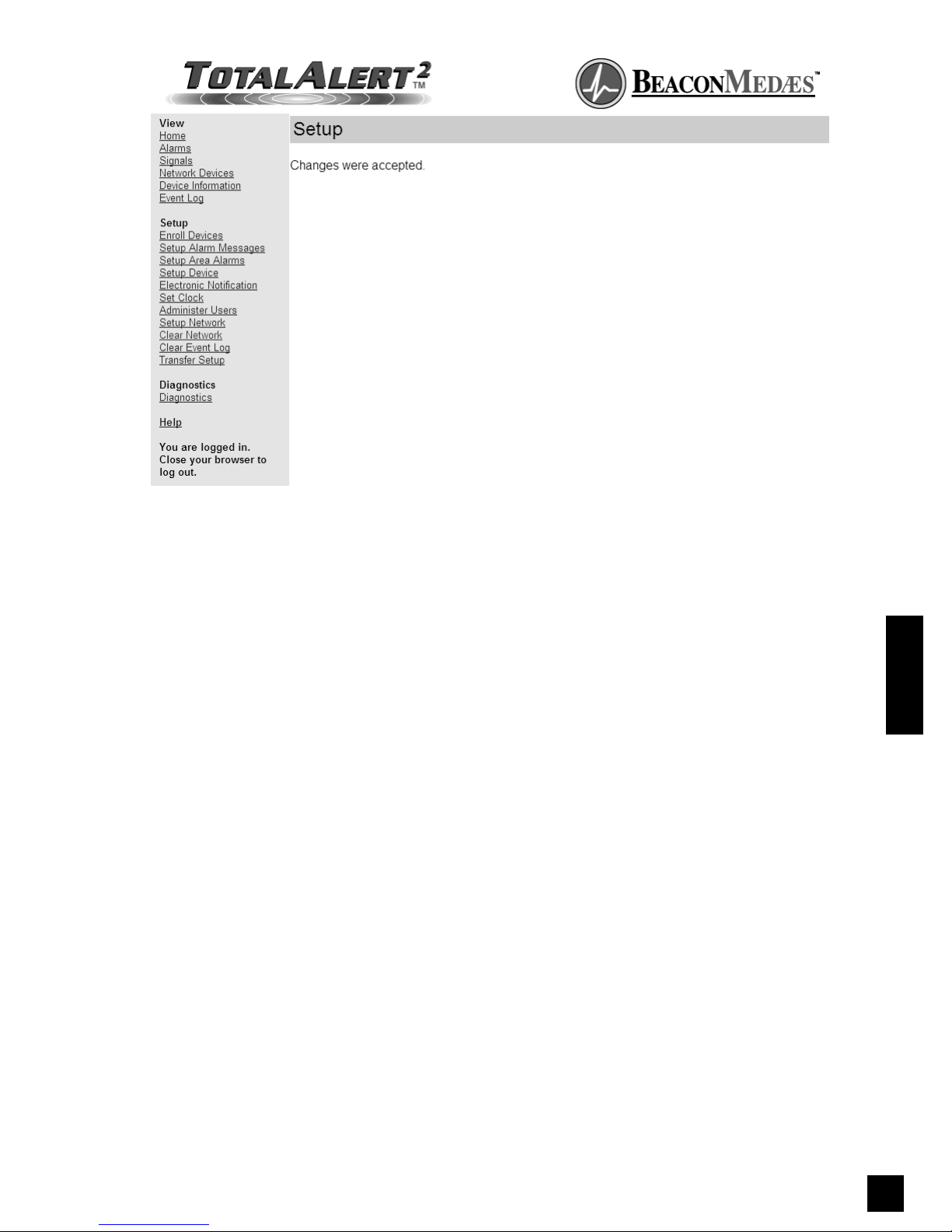
95
6-847718-00 Rev. B00
Figure 86: Clear Network Accepted
Operation
Page 98
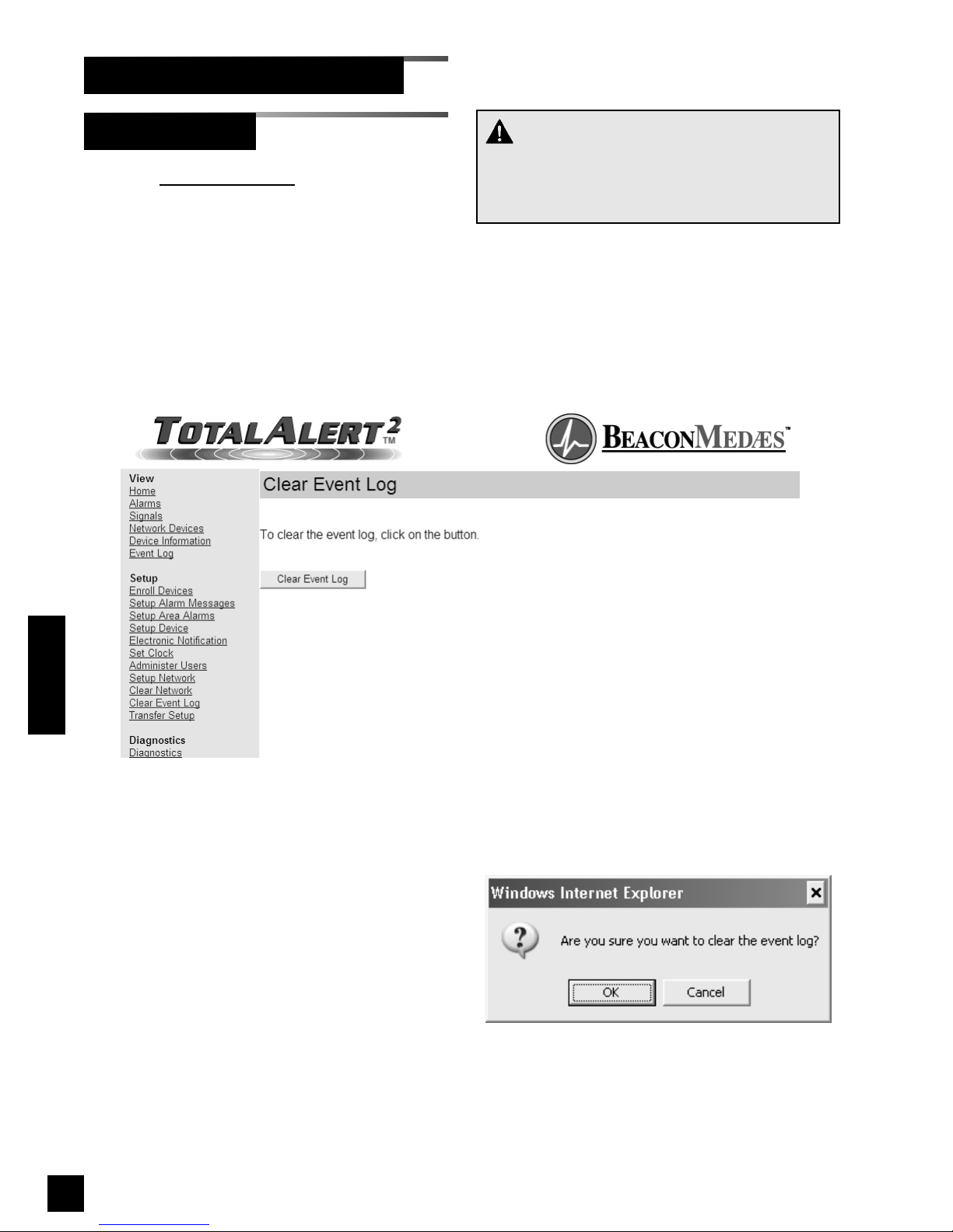
96
6-847718-00 Rev. B00
Clear Event Log
Set-Up Using Web Pages (Cont.)
1. Click Clear Event Log to access the
Clear Event Log page (Figure 87).
2. Click Clear Event Log.
3. The confirm clear event log dialog will
be displayed (Figure 88).
4. Click OK to clear the event log.
5. The Event Log page will display
(Figure 89)
Figure 88: Confirm Clear Event Log
CAUTION:
Be sure to save the event log prior to clearing it.
It is impossible to recover the event log after it is
cleared.
Operation
Figure 87: Clear Event Log
Page 99
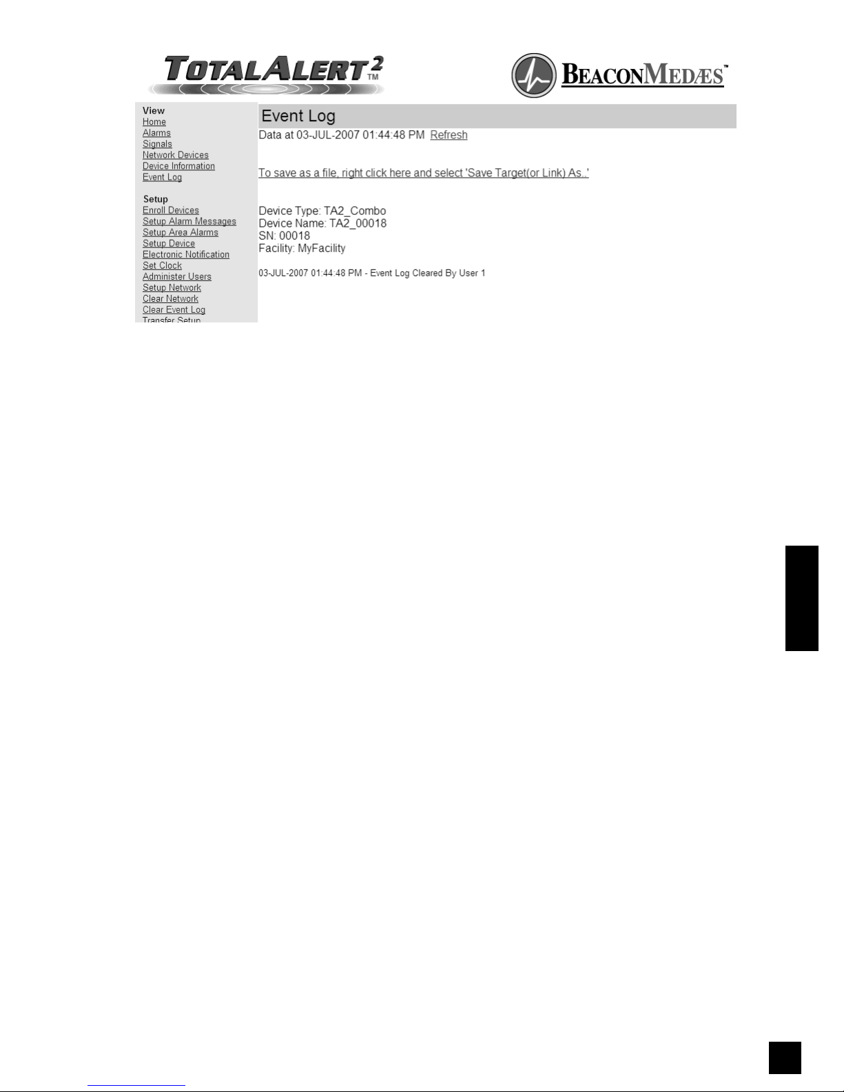
97
6-847718-00 Rev. B00
Operation
Figure 89: Event Log Cleared
Page 100
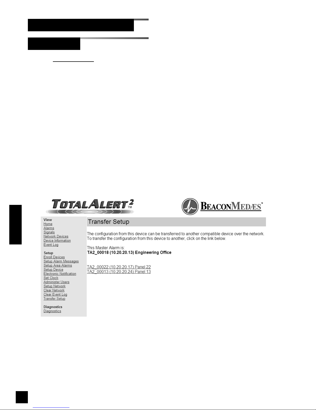
1. Click Transfer Setup to access the
Transfer Setup page (Figure 90).
2. A list of compatible master alarms will
be displayed.
3. Click on the link for the alarm that will
receive the settings.
4. Click Transfer Setup to transfer the
settings (Figure 91).
5. The Transfer Setup Complete page will
be displayed (Figure 92)
98
6-847718-00 Rev. B00
Transfer Setup
Set-Up Using Web Pages (Cont.)
Operation
Figure 90: Transfer Setup List
 Loading...