

Page 1

Installation, Operation and Maintenance Instructions
Andersen Medical Gas
12 Place Lafifitte
Madisonville, LA 70447
http://www.TheMedicalGas.com
1-866-288-3783
MEGA3 NFPA Medical Gas Notification System
Part number 4107 9016 59
Revision 03
August 27, 2015
Page 2

Page 3

Installation, Operation and Maintenance Manual
MEGA3 NFPA Medical Gas Notification System
This unit is purchased from:
Date purchased:
Model number:
Part number:
Option(s) included:
Any information, service or spare parts requests should be directed to:
BeaconMedæs
1800 Overview Drive
Rock Hill, SC 29730
Telephone: (888) 463-3427
Fax: (803) 817-5750
BeaconMedæs reserves the right to make changes and improvements to update products sold
previously without notice or obligation.
Part number 4107 9016 59
Revision 03
August 27, 2015
Page 4

Page 5

MEGA3 NFPA Medical Gas Notification System
Table of Contents
1.0 Introduction
1.1 Product Identification
1.2 User Interface Layout
1.2.1 MEGA3 Features
1.2.2 Master Alarm
1.2.3 Area Alarm
1.2.4 Combination Alarm
1.2.5 Boards
1.3 Definition of Statements
1.4 Definitions
1.5 Alarm Configurations
1.5.1 Master Alarms
1.5.2 Area Alarms
1.5.3 Gas Combination Alarms
1.6 MEGA3 Medical Gas Notification System Parent Model Number Chart
2.0 Installation Procedures
2.1 Alarm Panel Rough-In Box
2.2 Gas Sensor Installation
2.2.1 Local Sensors
2.2.2 Remotely Installed Sensors in Pipeline
2.2.3 Remotely Installed Sensors in Zone Valve Box
2.3 Wiring
2.3.1 General Requirements
2.3.2 Wire Type And Size
2.3.3 Determining Number Of Conductors
2.3.4 Power Supply
2.3.5 B60 Gas Input Board
2.3.6 B1X Signal Input Board
2.3.7 B4X Relay Output Board
2.3.8 B50 4-20mA Combination Board
2.3.9 General Fault Relay
2.3.10 Field Wiring Cable Shield Grounding
i
4107 9016 59.03
Page 6

MEGA3 NFPA Medical Gas Notification System
Table of Contents (continued)
2.4 Finish Assembly
2.4.1 Front Panel Mounting
2.4.2 Locally Installed Sensors
2.4.3 Remotely Installed Sensors in Pipeline
3.0 Wiring Schematics
3.1 NFPA Master Wiring Diagram
3.2 NFPA Area Wiring Diagram
3.3 NFPA Combination Wiring Diagram
4.0 Operation
4.1 Overview
4.1.1 Main Screen
4.1.2 Gas Badge
4.1.3 Source Signals
4.1.4 Toolbar
4.1.5 Fault Status
4.1.6 Display Screens
4.2 Alarm Configuration
4.3 Setting Up an Area Alarm
4.3.1 Configuring Gas ID Badges
4.3.2 Initial Setup of an Unconfigured Area Alarm
4.4 Setting Up a Master Alarm
4.4.1 Configuring Source Badges
4.4.2 Initial Setup of an Unconfigured Master Alarm
4.5 Setting Up a Combination Alarm
4.5.1 Configuring Source Badges
4.5.2 Configuring Gas ID Badges
4.5.3 Initial Setup of an Unconfigured Combination Alarm
4.5.4 Miscellaneous Tab
4 .6 Additional Components
4.6.1 4-20 mA Devices
4.6.2 Relay Output Board (B4X Board)
5.0 Retrofit
5.1 Retrofit of TotalAlert2 Area Alarm Panel (4-gas, 8-gas) and MEGA2 Alarms
5.1.1 Remove Components from Existing Alarm
5.1.2 Install New Power Supply
4107 9016 59.03
ii
Page 7

MEGA3 NFPA Medical Gas Notification System
5.1.3 Install New Components
5.1.4 Install Trim Plate
5.2 Retrofit of TotalAlert1 Alarm Panels
5.2.1 Remove Components from Existing Alarm
5.2.2 Install Gas-Specific Sensors (Area or Combination alarms only)
5.2.3 Install New Power Supply
5.2.4 Install New Components
5.2.5 Install Trim Plate
5.3 Retrofit of Other Alarm Panels
5.3.1 Remove Components from Existing Alarm
5.3.2 Determine Proper Placement of New Components
5.3.3 Install Gas-Specific Sensors (Area or Combination alarms only)
5.3.4 Install New Power Supply
5.3.5 Install I/O Modules
5.3.6 Install Trim Components
5.3.7 Install Front Panel
6.0 Maintenance
7.0 Troubleshooting
iii
4107 9016 59.03
Page 8

Page 9

MEGA3 NFPA Medical Gas Notification System
1.0 Introduction
1.1 Product Identification
Each alarm is identified by a Model number,
Part number, and Lot Code.
Installation procedures vary depending on
the alarm configuration.
The product ID label is located on the inside
of the alarm back box (Figure 1).
1.2 User Interface Layout
Home
Button
Mute Indicator LED
Power LED
Warning LED
Mute ButtonHorn
Figure 2: User Interface Layout
1.2.1 MEGA3 Features:
• 10.2” Touch Screen LCD display.
• Green alarm panel POWER LED indicator.
• Red alarm system WARNING LED
indicator.
• Red alarm MUTE INDICATOR LED.
• Audible alarm horn
• Heartbeat LED to indicate proper
operation on internal printed circuit
boards and gas sensor assemblies.
Figure 1: Product Identification Labels
1.2.2 Master Alarm
Features:
Monitors up to 40 normally closed dry-contact switch signals.
• Forty gas service indicators for normal
(green) or abnormal (red) conditions.
1-1
4107 9016 59.03
Page 10

MEGA3 NFPA Medical Gas Notification System
1.2.3 Area Alarm
Monitors up to 8 digital gas sensors.
Features:
• Digital pressure/vacuum read out with
Low/Normal/High indicators
• Rough-in box capable of holding 8 locally
mounted sensors.
• Customizable Gas ID labels with location
• General fault relay that activates on any
pressure/vacuum fault condition
1.2.4 Combination Alarm
Monitors a mix of normally closed dry-contact switch signals, 6 digital gas pressure/
vacuum signals, and provides dry-contact
relay outputs.
1.2.5 Boards
B06 Digital Gas Sensor Board
Features:
• Monitors the Pressure/Vacuum from the
pipeline, and provides a gas-specific digital signal for the alarm.
• Heartbeat indicator to indicate proper
operation.
• Embedded in gas sensor assembly.
NOTE:
I = 4-20mA Inputs
X = Source Signal Inputs
Y = Dry-Contact Relay Outputs
D = Digital Gas Sensor Inputs
B05 Power Supply Board
Features:
• Supplies 24VDC to all circuit boards in
the alarm
Figure 4: B06 Digital Gas Sensor Board
B10, B11 NFPA Signal Input Board
Features:
• Monitors up to 20 normally closed drycontact switch signals on each board
• Heartbeat indicator to signal proper operation.
Figure 3: B05 Power Board
4107 9016 59.03
Figure 5: B10, B11 Signal Input Board
1-2
Page 11

MEGA3 NFPA Medical Gas Notification System
B40, B41, B42, B43 Relay Output Board
Features:
• Provides 16 normally closed dry-contact
relay outputs for external monitoring.
• Heartbeat indicator to indicate proper
operation.
Figure 6: B40, B41, B42, B43 Relay Output Board
B50 4-20mA Combination Board
B60 Gas Input Board
Features:
• Monitors up to 8 Digital Gas Sensor
Boards. One normally closed dry-contact
relay output is available and opens when
any fault occurs.
• Heartbeat indicator to signal proper operation.
Figure 8: B60 Gas Input Board
B65 Gas Combination 3D, 10X, 6Y Board
Features:
• Monitors up to 4 4-20mA inputs, 7 normally closed dry-contact switch signals,
and provides 6 normally closed dry-contact relay outputs for external monitoring.
• Heartbeat indicator to indicate proper
operation.
Figure 7: B50 4-20 mA Combination Board
Features:
• 3 Gas Sensors, 10 inputs, 6 outputs
Figure 9: B65 Gas Combination 3D, 10X, 6Y Board
1-3
4107 9016 59.03
Page 12
MEGA3 NFPA Medical Gas Notification System
1.3 Definition of Statements
Statements in this manual preceded by the
following words are of special significance.
WARNING: Means there is a possibility
of injury or death to yourself or others.
CAUTION: Means there is a possibility of
damage to unit or other property.
SHOCK HAZARD: Means there is a
possibility of electric shock.
ATTENTION: Means precautions for handling electrostatic sensitive devices are
to be observed.
NOTE: Indicates points of particular interest
for more ecient and convenient operation.
1.4 Definitions
Address Resolution Protocol (ARP)
Protocol used by a device to learn the MAC
address of another device so it can send an
Ethernet packet.
Area Alarm Panel
Alarm panel that monitors medical gas and
vacuum systems serving a specific area.
Combination Alarm Panel
Alarm panel that combines features of a master alarm panel and an area alarm panel.
4-20 mA
Input which monitors a two or three wire
4-20mA transducer.
Crossover Cable
Network cable that swaps transmit and receive pairs so cable can be used to connect
two computers or devices without the use of
a hub or switch.
Domain Name Server (DNS)
A device that has a list of device names
matched to IP addresses. Browsers use this
resource to locate the IP address of a named
device. NetBIOS name service provides this
function on a local network.
Dry-Contact
Electrical contact isolated or unconnected
from any electrical source.
Dynamic Host Configuration Protocol
(DHCP)
A protocol used by a server to assign IP
addresses to devices and computers.
Electromagnetic Compatibility (EMC)
Verification that a product meets required
standards for emissions of and immunity
from electromagnetic energy in its intended
environment.
Ethernet
A standard high-speed network medium
specified by IEEE standard 802.3.
4107 9016 59.03
1-4
Page 13

MEGA3 NFPA Medical Gas Notification System
Ethernet Switch
A device that connects many Ethernet devices
together with optimization. Message destinations are examined and passed only to the
correct device.
Firewall
A computer or computer software that prevents unauthorized access to private data
from outside computer users.
Gateway
A computer or device that connects two computer networks together (such as a private
network and the Internet).
General Fault Relay
Single-pole single-throw dry-contact relay
output. Used to activate remote alarm or
building management system. Relay will
open whenever ANY audible alarm on panel
is in progress. General Fault Relay will deactivate only after alarm condition is corrected
and alarm panel resumes normal status.
HyperText Transfer Protocol (HTTP)
Protocol used to manage the request and
transfer of web pages to a computer.
Internet Protocol (IP) Address
Unique number that identifies a device on a
network.
LED
Light Emitting Diode
Local Sensors
Pressure / vacuum sensors mounted inside
alarm panel back box. Sensor assembly must
be piped to medical gas / vacuum pipelines.
Media Access Control (MAC) Address
A unique hardware address of a device on an
Ethernet.
NetBIOS Name Service
Local method of addressing a device by
name. This allows a web browser to reference
a device by name instead of an IP address,
such as 192.168.2.3.
Remote Sensors
Pressure / vacuum sensors mounted outside
of alarm panel back box. Sensor assembly
may be mounted separately or ganged together near pressure / vacuum pipelines.
Sensors must then be wired to alarm panel.
Simple Mail Transfer Protocol (SMTP)
Protocol for sending e-mail on a network.
Subnet Mask
A binary number used to separate the network portion from the host portion of a
network address.
SMTP Client
Computer or device that uses SMTP to send
e-mail by communicating with an SMTP
server. The MEGA3 alarm panel acts as an
SMTP client.
SMTP Server
Computer or device that uses SMTP to receive
email from an SMTP client and then transfer
it across the internet.
Transmission Control Protocol (TCP)
Protocol used to send data streams between
two devices. TCP guarantees reliable and in
order data from sender to receiver.
User Datagram Protocol (UDP)
Protocol used to send short messages between computers. UDP does not guarantee
reliable transmission (packets may be lost,
duplicated or out of order), but is faster and
more ecient than TCP.
Master Alarm Panel
Alarm panel that monitors medical gas and
vacuum source equipment and main pipelines.
1-5
4107 9016 59.03
Page 14

MEGA3 NFPA Medical Gas Notification System
1.5 Alarm Configurations
All MEGA3 alarm panels are factory pre- configured. Configuration of alarm panel varies
dependent upon customer’s requirements.
Three types of alarm panels are available.
• Master alarms
• Area alarms
• Combination alarms
1.5.1 Master Alarms
Master alarm panels include the following
modular components:
• Signal input boards (B10, B11) that can
accept 20 signals per board; maximum of
2 boards.
• Relay boards (B40, B41, B42, B43) that
can be used to control 16 dry-contact signals per board; maximum of 4 boards.
Master alarm panels can monitor 20 or 40
switched inputs.
1.5.2 Area Alarms
Area alarm panels include the following modular components:
• Gas Sensor input board (B60) that can be
used for up to 8 digital gas sensors.
• Digital gas sensor assembly, can be
mounted locally in the rough-in box, remotely on the gas pipeline, or in a compatible BeaconMedæs Zone Valve Box.
Maximum of 8 digital gas sensor assemblies per area alarm panel.
Area alarm panels may be configured for 1 to
8 gas inputs. If alarm is configured with gas
inputs, the sensors will be included for connection to pressure/vacuum pipeline.
Sensors may be located inside the alarm
rough-in (local sensors) utilizing the DISS
inlet tube assemblies provided for brazing to
the hospital pipelines.
Copper tubes
connect to
pressure/vacuum
pipelines
Inputs can be assigned to any gas service
indicators.
Model Number Scheme:
____ - ________ - __ -_____
Series - Configuration - Gas - Retrofit
See Model Number Chart in Section 1.6.
Example:
MEGA3 Master 40X 32Y
Example Model Number: M3-M22
Figure 10: Master Alarm Front Panel
Sensor modules are
mounted inside alarm
panel box
Figure 11: Local Sensors
Sensors may be located outside the alarm
rough-in (remote sensors) utilizing the DISS
inlet tube assembly or by an 1/4”NPT port.
4107 9016 59.03
1-6
Page 15

MEGA3 NFPA Medical Gas Notification System
Copper tubes
connect to pressure/
vacuum pipelines
Sensor modules are
mounted outside alarm
rough-in
Figure 12: Remote Sensors
Model Number Scheme:
____ - ________ - __ -_____
1.5.3 Gas Combination Alarms
Gas Combination alarms include the following modular components:
• B1X, B60 or B65 boards
• 4-20 mA Combination - Can be added to
any alarms (if room)
Combination alarms can monitor 30
switched inputs.
Optional dry contact relays are available for
all signals.
Combination alarms can also monitor up to 6
digital gas sensors.
Model Number Scheme:
____ - ________ - __ -_____
Series - Configuration - Gas - Retrofit
See Model Number Chart Section 1.6.
Example:
MEGA3 Area OAV
Example Model Number: M3-A10-OAV
Series - Configuration - Gas - Retrofit
See Model Number Chart on Section 1.6.
Example:
MEGA3 Combination
20X 16Y 8D OVOV
Example Model Number: M3-C21-OVOV
Figure 13: Area Alarm Front Panel
Figure 14: Combination Alarm Front Panel
1-7
4107 9016 59.03
Page 16
MEGA3 NFPA Medical Gas Notification System
1.6 MEGA3 Medical Gas Notification System Parent Model Number Chart
M3 - ___ - _
B C
Variable B
Alarm Type and Size
Allowable Value Description
M01 Master, 0 Inputs, 16 Relay Outputs
M10 Master, 20 Inputs
M11 Master, 20 Inputs, 16 Relay Outputs
M12 Master, 20 Inputs, 32 Relay Outputs
M13 Master, 20 Inputs, 48 Relay Outputs
M20 Master, 40 Inputs
M21 Master, 40 Inputs, 16 Relay Outputs
M22 Master, 40 Inputs, 32 Relay Outputs
A10 Area Alarm, Up to 8 Area Gases
C01
C10*
C11*
C12*
C40
C41*
C44*
Notes:
* Limitations on Combination Panels:
• C10, C11, C12 Combinations
x 0-10 source signal Inputs used, Display up to 6 Area gases
x 11-20 source signal Inputs used, Display up to 4 Area gases
• C41
x 0-20 source signal Inputs used, Display up to 4 4-20mA
devices
x 21-27 source signal Inputs used, Display up to two 4-20mA
devices
• C44
x Display up to 6 gas badges maximum, combination of
4-20mA and area gases, with maximum 4 4-20mA badges.
Combination, 10 Inputs, 6 Relay Outputs, Up to 3 Area Gases
Combination, 20 Inputs, Up to 6 Area
Gases
Combination, 20 Inputs, 16 Relay
Outputs, Up to 6 Area Gases
Combination, 20 Inputs, 32 Relay
Outputs, Up to 6 Area Gases
Combination, 7 Inputs, 6 Relay Outputs, 4 Inputs for 4-20mA devices
Combination, 27 Inputs, 6 Relay Outputs, 4 Inputs for 4-20mA devices
Combination, 7 Inputs, 6 Relay Outputs, 4 Inputs for 4-20mA devices, Up
to 6 Area Gases
Variable C
Gas Type (Area and Combination Only)
Allowable Value Description
O Oxygen
X Nitrous Oxide
A Medical Air
V Medical Vacuum
W WAGD
N Nitrogen
C Carbon Dioxide (CO2)
D Oxygen 100 psig
F Medical Air 100 psig
G Carbon Dioxide 100 psig
9 Instrument Air
1 CO2-O2 (CO2 over 7%)
2 O2-CO2 (CO2 not over 7%)
3 HE-O2 (HE over 80%)
4 O2-HE (HE not over 80%)
7 Laboratory Air
8 Laboratory Vacuum
H Helium
J Argon
S Surgical Air
B AGSS
E N2O-O2
M Mixed Gas
NOTE:
Standard configurations listed above. For
special configurations contact BeaconMedaes Customer Service (888) 463-3427.
4107 9016 59.03
1-8
Page 17

MEGA3 NFPA Medical Gas Notification System
2.0 Installation Procedures
2.1 Alarm Panel Rough-In Box
The rough-in box can be installed between
16” on center standard studs. Mounting
ears on either side of the rough-in box are
provided for attachment to studs, with depth
adjustment to accommodate dierent thicknesses of wall board.
Knock out plugs are provided in the top and
bottom of the box for routing of supply power, Ethernet CAT5 cable, gas sensor tubes, or
other necessary wiring.
DO NOT drill rough-in box.
1. Prepare rough wall opening large enough
to accommodate alarm rough-in box.
Alarm rough-in box must have rigid vertical members for support on both left and
right sides. Power to alarm panel shall enter through bottom left or top left conduit
hole in rough-in box.
2. Remove cardboard dust cover and DISS
tube assemblies (if included) and insert
alarm rough-in box into wall opening.
[Secure with fasteners suitable for vertical
supports (Figure 16)].
3. Mounting brackets on each side of roughin box are adjustable and factory preset
for 5/8” thick drywall. After drywall
installation, front edge of rough-in box
should be flush with finished surface
of wall. If needed, make any necessary
bracket adjustments at this time (Figure
16).
4. Reinstall cardboard dust cover to prevent
dust and debris from entering the roughin box.
13.50”
10”
4”
Figure 15: Alarm Panel Rough-In Box Dimensions
Loosen nuts to adjust
rough-in box depth
(same each side)
Figure 16: Mounting Bracket Adjustment
2-1
4107 9016 59.03
Page 18

MEGA3 NFPA Medical Gas Notification System
2.2 Gas Sensor Installation
2.2.1 Locally Installed Sensors
1. Locate copper adapter tube(s) packaged
inside the alarm rough-in box.
2. Install tube(s) into the top of the roughin box through the holes provided.
Notice the Gas ID labels and position
appropriately for connection to the
hospital piping. Apply Gas ID label
provided with tube adapter to the
inside of the rough-in box to identify
the ports after walls are closed in.
3. Braze copper adapter tube(s) to
appropriate pressure/vacuum piping
system drops (Figure 17). Braze
connections per procedures required
by NFPA 99 or CAN/CSA-Z7396.1-12.
Use appropriate measures to prevent
overheating.
4. Install the Gas Specific DISS check valve
into the appropriate tube adapter.
2.2.2 Remotely Installed Sensors in
Pipeline
1. Sensors can be installed onto the hospital
pipeline.
2. Braze copper adapter tube(s) to
appropriate pressure/vacuum piping
system connections (Figure 18).
3. Braze connections per procedures
required by NFPA 99 or CAN/
CSA-Z7396.1-12
4. Use appropriate measures to prevent
overheating.
5. Install the Gas Specific DISS check valve
into the appropriate tube adapter.
6. Perform standing pressure test and cross
connection tests as required by NFPA and
CSA.
Connection should
be made on top of
pipe
REMOTE SENSOR
5. Perform standing pressure test and cross
connection tests as required by NFPA and
CSA.
Connection should
be made on top of
pipe
LOCAL SENSOR
Figure 18: Remote Pipeline Installation
2.2.3 Remotely Installed Sensors in
Zone Valve Box
1. Remote sensors can be installed in a
compatible BeaconMedæs Zone Valve
Box. (NOTE: copper adapter tube not
needed for Zone Valve box installation
(Figure 19).
2. For Zone Valve Box mounting, an
additional Installation Kit is required, part
number 4107 4016 25 for each sensor.
Figure 17: Sensor Pipeline Connection
4107 9016 59.03
2-2
Page 19

MEGA3 NFPA Medical Gas Notification System
2.3.2 Wire Type and Size
All low voltage wiring must meet the following criteria:
• Copper wire no smaller than 22 AWG,
conductor insulation at least 0.010in
(0.25mm), jacket insulation at least
0.030in (0.76mm), rated for 300V and
60°C (140°F) minimum.
• Circuit length not to exceed 5000 feet.
• Cable must be twisted-pair shielded type.
Multi-pair cables within one common
Figure 19: Zone Valve Box Location
shield are acceptable.
2.3 Wiring
2.3.1 General Requirements
1. All alarms are to be powered from life
safety branch of emergency power system
as required by applicable standards.
2. Protect all wiring from physical damage
by raceways or conduit as required by applicable standards.
3. Wire alarm panels directly to switches or
sensors as required by applicable standards.
4. Wiring runs should be made with color
coded wire. Record color, signal, and
source of signal for each wiring lead to
aid in connection of alarm finish components.
5. Avoid installing alarm panels near radio
transmitters, electrical motors, or switch
gear.
2.3.3 Determining Number of
Conductors
The following rules along with references
to this manual’s schematics clarify wiring
requirements.
• Digital Gas Sensor Modules
Two conductor cables (must be twisted pair
type with shield) are required for each Gas
Sensor module to the Gas Input board.
Refer to NFPA Area Wiring Diagram (Section
3.2).
• Switched signal inputs
Two conductor cables (must be twisted pair
type with shield) are required for each signal
between the signal input terminals and the
source signal switch.
These signals can originate at source equipment or from pressure switches mounted on
main pressure / vacuum pipelines.
When two master alarms are required, the
same switch / relay contacts can be wired to
both alarm panels. (See CAUTION below).
Both pairs of wires should originate from
switch/relay contacts.
2-3
4107 9016 59.03
Page 20
MEGA3 NFPA Medical Gas Notification System
Refer to NFPA Master/Combination Wiring
Diagram (Section 3.1/3.3) for B1X, B50, B65
signal boards.
• Relay outputs
Two conductors are required for each signal
between relay output terminals and remote
device (such as a building automation system). Refer to the wiring requirements of the
connecting device when selecting the appropriate type of conductors to use (i.e.. wire
gauge, twisted or not, shielded or not.)
Refer to NFPA Master/Combination Wiring
Diagram (Section 3.1/3.3) for B4X, B50, B65
signal boards.
2.3.4 Power Supply
A power supply assembly is provided with
the alarm panel. The installer must use
18AWG copper supply wiring minimum
with an insulation of not less than 1/32 inch
(0.8mm) thick. Power supply shall be connected to a building installed circuit breaker.
Circuit breaker shall be a maximum of 15
amps and marked as disconnecting means for
the alarm panel. It is recommended that the
circuit breaker be in close proximity to the
alarm panel and properly selected according
to local and national regulations.
CAUTION:
Do not connect MEGA3 master/combination alarm to switch/relay contacts connected to any alarm panels other than those
listed below:
• TotalAlert Infinity
• TotalAlert 2
• MEGA3
• MEGA2
• MEGA
™
Holes are provided in the top and bottom of
the rough-in box for main power (Figure 20).
If power is entering from the top, it must be
routed under the cable raceway.
NO OTHER HOLES SHOULD BE PUNCHED
OR USED.
Several additional holes or knockouts are provided on the top panel and bottom for entrance of low voltage field wiring (Figure 20).
Contractor to install
UL rated strain relief or
conduit connector
Cable Raceway
Power Supply
Wire Entrance
for power cable
(alternate)
Figure 20: Wire Routing
NOTE:
All wiring shall be protected from physical damage
by raceways or conduit in accordance with NFPA 70,
National Electric Code.
Alarm panels require 100 to 250 VAC
0/60 Hz 250mA power. NFPA Area Wiring
Diagram (Section 3.2).
4107 9016 59.03
2-4
Page 21
MEGA3 NFPA Medical Gas Notification System
For NFPA 99 compliance, alarm panel must
be connected to life safety branch of the
emergency electrical system.
1. Remove four screws from plastic power
supply shield.
2. Remove plastic shield from power supply.
3. Connect incoming line and neutral wires
to the terminal block. Ground wire connects directly to the rough-in box (chassis)
at the green screw below the power supply (Figure 21).
4. DO NOT remove or alter the Green factory installed ground wire from the terminal
block to chassis.
5. Reinstall plastic power supply shield
while making sure all high voltage wires
are contained within plastic shield.
6. Secure plastic shield with four screws.
2.3.5 B60 Gas Input Board
An Area alarm has 8 Gas Inputs. Signals are
numbered D01 thru D08. There is a single
relay output for general gas fault notification.
1. Identify each pair of twisted gas sensor
wires inside the alarm rough-in box.
2. Route each pair of sensor wires as shown
(Figure 23) to appropriate terminals.
3. Connect each pair of sensor wires to
terminal blocks noting the correct polarity Red (+), Black (-). NFPA Area Wiring
Diagram (Section 3.2)
NOTE:
If gas sensor wires are landed on the terminal blocks
in the same order as defined by the model number
of the alarm panel, then initial setup will be easier
and gas sensor channels will not need to be reconfigured.” Example T3-A10-OAV means “O” Oxygen
is defaulted to D01, “A” Medical Air is defaulted to
D02, etc. See Section 1.6.
Line Voltage
Neutral
Ground
Figure 21: Supply Power Wiring
WARNING:
RISK OF ELECTRIC SHOCK
Disconnect power at the circuit breaker
before removing power supply shield.
Holes provided for
entrance of remote
wiring
2-5
Figure 22: Remote Sensor Wire Routing
4107 9016 59.03
Page 22
MEGA3 NFPA Medical Gas Notification System
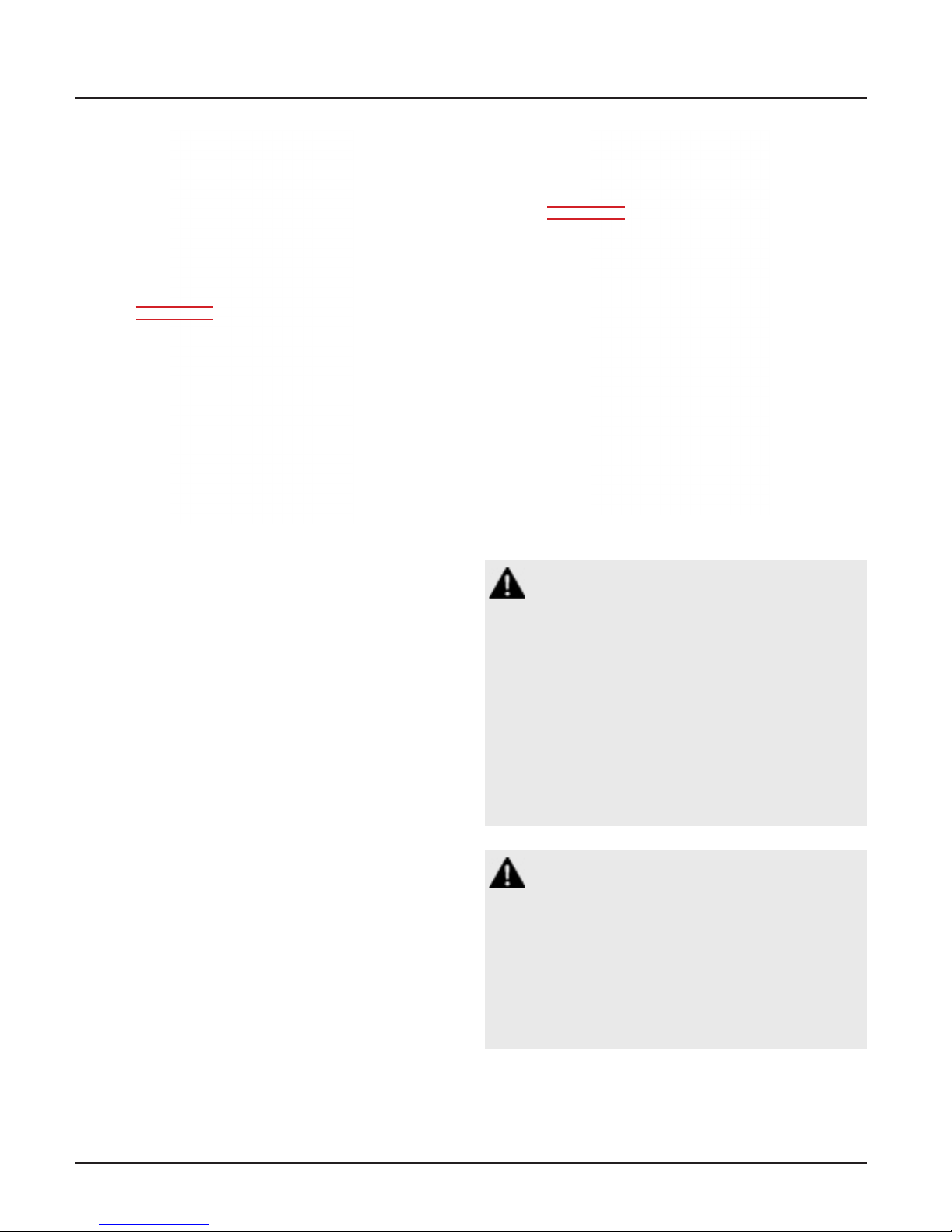
Figure 23: B60 Board Wire Routing
2.3.6 B1X Signal Board
A Master or Combination alarm panel can
contain multiple signal input boards; up to a
maximum of 2 boards or 40 signal inputs.
B10 and B11boards are labeled X01 thru
X20.
Identify each twisted pair of field installed
signal input signal wires inside the alarm
rough-in box.
Route each pair of signal input signal wires as
shown in Figure 24 to appropriate terminals
on input board(s).
Connect each pair of signal wires to terminal
blocks noting the correct polarity (+,-). Refer
to NFPA Master/Combination Wiring Dia-
gram (Section 3.1/3.3).
Figure 24: B1X Signal Board Wire Routing
CAUTION:
Do not connect MEGA3 master/combination alarm to switch/relay contacts connected to any alarm panels other than those
listed below:
• TotalAlert Infinity
™
• TotalAlert2
• MEGA3
• MEGA2
• MEGA
CAUTION:
Source equipment signal wires must be
connected to normally-closed, dry contacts. No electrical voltage can be present
and contacts must be closed during normal
equipment operation. When contacts open,
an alarm condition will be activated.
4107 9016 59.03
2-6
Page 23

MEGA3 NFPA Medical Gas Notification System
NOTE:
Each pair of terminals labeled on the signal
board connector is labeled “+” and “-”. Ensure
that when a source equipment dry contact is
wired to two master panels, the same side of
the dry contact is connected to the same terminal at both panels. For example, if the source
equipment’s normally closed contact is wired to
the “+” of the first master panel, ensure it is also
connected to the “+” terminal of the second
master panel.
2.3.7 B4X Relay Output Board
A Master or Combination alarm can contain
multiple relay output boards; up to a maximum of 4 boards with 16 relay outputs each.
The B4X boards (B40, B41, B42, B43) utilize
normally closed dry contact relay outputs.
Figure 25: B4X Board Wire Routing
The outputs on the B4X boards are labeled
Y01 through Y16.
Identify each pair of field installed relay
output signal wires inside the alarm rough-in
box. Route each pair of relay output wires as
shown in Figure 25 to the appropriate terminals on the relay board. Connect each pair of
signal wires to the terminal blocks, noting the
correct polarity (+,-). Refer to NFPA Mas-
ter/Combination Wiring Diagram (Section
3.1/3.3).
2-7
4107 9016 59.03
Page 24

MEGA3 NFPA Medical Gas Notification System
2.3.8 B50 4-20mA Combination
Board
A Combination alarm can contain a B50
board that contains four 4-20mA inputs that
can be used with a 2 or 3 wire transmitter.
The board also contains seven signal inputs,
which monitor normally closed signal inputs,
and six normally closed dry contact relay outputs. Each alarm panel can have a maximum
of one B50 board.
Identify each set of field installed 4-20mA
input signal wires (2 or 3 wires per set) inside
the alarm rough-in box. Route each set of input wires to the appropriate terminals on the
B50 board. Connect each set of signal wires
to the terminal blocks, noting the correct
polarity (Figure 26).
2.3.9 General Fault Relay
The B60 Gas Input board is supplied with an
alarm panel general fault output relay.
This relay has a set of dry contacts that is
wired normally closed.
The relay will activate when ANY alarm on
the ENTIRE alarm panel is activated. Relay
will remain activated as long as alarm condition is active, even if audible alarm is silenced
by MUTE button.
When alarm condition is corrected, relay will
deactivate. Relay contact ratings are 35A @
30VDC / 3A @ 250VAC. Refer to NFPA Area
Wiring Diagram (Section 3.2).
2.3.10 Field Wiring Cable Shield
Grounding
Figure 26: B50 Board Wire Routing
All field wiring cable shields must be grounded inside alarm panel rough-in box.
Holes are provided in the top and bottom of
the alarm rough-in box for grounding screws
(Figure 27).
Shields from several cables may be wrapped
together and crimped into one screw (by others).
4107 9016 59.03
Grounding Holes Provided
Figure 27: Cable Shield Grounding-Area
2-8
Page 25
MEGA3 NFPA Medical Gas Notification System
CAUTION:
Keep shield wires to ground screw as short
as possible so they can not touch front
panel circuit boards when front panel is
closed.
2.4 Finish Assembly
2.4.1 Front Panel Mounting
ATTENTION:
Observe Precautions for Handling
ELECTROSTATIC SENSITIVE DEVICES
Ground Lug
Figure 28: Front Panel Screws
1. Remove front panel assembly from packaging.
2. Remove front panel mounting screws from
alarm panel rough-in box assembly (Figures 28).
3. Remove lanyard mounting nut from alarm
panel back box assembly (Figure 28).
4. Attach front panel to alarm panel roughin box using screws removed in step 2
(Figure 29).
5. Attach lanyard to alarm panel back box
using screws removed in step 3.
6. Remove nut from front panel grounding
lug.
7. Install front panel grounding wire using
nut removed in step 6.
8. Connect the grey cable on the front panel
to the open power/communication port
on the power supply.
Figure 29: Attach Front Panel and Lanyard
NOTE:
Harness connector is keyed to prevent
incorrect orientation. However, use care to
ensure correct pin alignment.
2-9
4107 9016 59.03
Page 26

MEGA3 NFPA Medical Gas Notification System
2.4.2 Locally Installed Sensors
1. Remove sensor module from shipping
carton.
2. Connect sensor with DISS fitting to the
appropriate DISS check at the top of the
rough-in box. Verify Gas ID labels match
between the sensor and piping to ensure
no cross connections occur. Repeat this
process for all sensors within alarm panel.
3. Connect wires into input terminals of B60
board (See section 2.4.2).
2.4.3 Remotely Installed Sensors in
Pipeline
1. Remove sensor from shipping carton.
2. Connect sensor with DISS fitting to the
appropriate DISS Check on the hospital
pipeline or BeaconMedæs Zone Valve box.
Verify Gas ID labels match between the
sensor and piping to ensure no cross connections occur.
3. Wire nut pigtail to field installed wiring.
Note polarity of wiring and corresponding
field wiring color or number for later (See
section 2.3.5).
NOTE:
Do not ground shield drain wire at sensor.
Figure 30: Local Sensor Mounting
NOTE:
If gas sensor wires are landed on the terminal
blocks in the same order as defined by the
model number of the alarm panel, then initial
setup will be easier and gas sensor channels
will not need to be reconfigured.” Example
T3-A10-OAV means “O” Oxygen is defaulted to
D01, “A” Medical Air is defaulted to D02, etc.
See section 1.6.
4107 9016 59.03
Figure 31: Remote Sensor Module Connection
2-10
Page 27
MEGA3 NFPA Medical Gas Notification System
3.0 Wiring Schematics
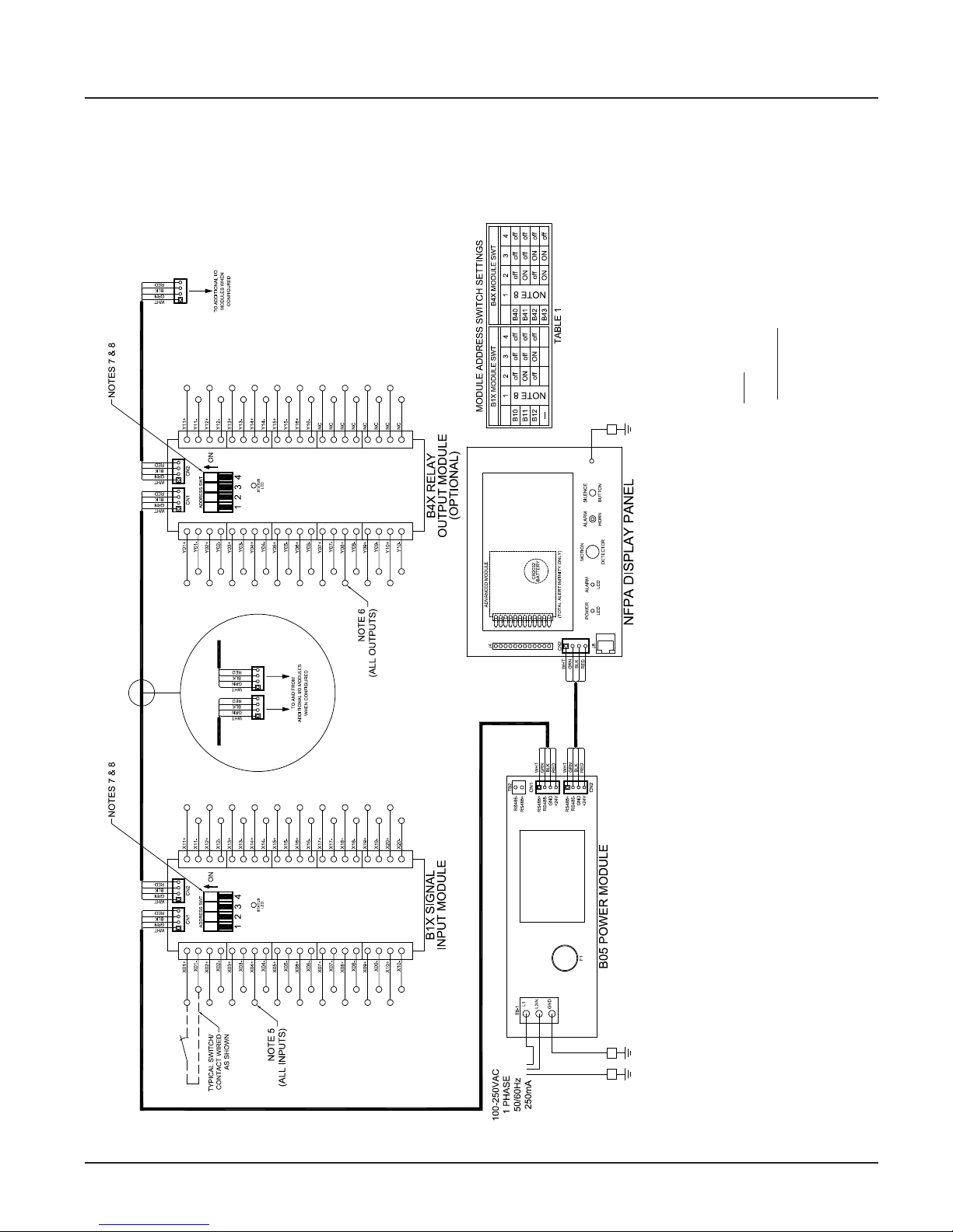
3.1 NFPA Master Wiring Diagram
MULTI-CONDUCTOR CABLE MUST BE TWISTED PAIR TYPE WITH SHIELD
Notes:
1. MAIN DISCONNECT PROVIDED BY OTHERS
2. FIELD POWER WIRING TO BE COPPER RATED FOR 75°C MINIMUM
3. FIELD SIGNAL WIRING TO BE MINIMUM 22AWG
TOTAL CIRCUIT LENGTH NOT TO EXCEED 10,000’ & MAX. 1K OHM
RESISTANCE
EQUIPMENT OR LINE PRESSURE SWITCHES.
VERIFY USING TABLE 1.
ONLY.
4. -- -- -- -- INDICATES FIELD WIRING OUTSIDE OF BOX.
5. INPUTS FROM DRY NORMALLY-CLOSED CONTACTS FROM SOURCE
6. RELAY OUTPUT CONTACTS RATED 3A / 30VDC MAX.
7. SEE MODULE LABEL TO SET MODULE ADDRESS (POSITIONS 2,3, & 4).
8. SET ADDRESS SWT POSITION 1 TO “ON” FOR LAST MODULE IN CHAIN
3-1
FACTORY WIRED
CHASSIS GROUND
ENCLOSURE
GROUND SCREW
Figure 32: Wiring Diagram for NFPA MEGA3 Master Alarm
4107 9016 59.02
Page 28
MEGA3 NFPA Medical Gas Notification System
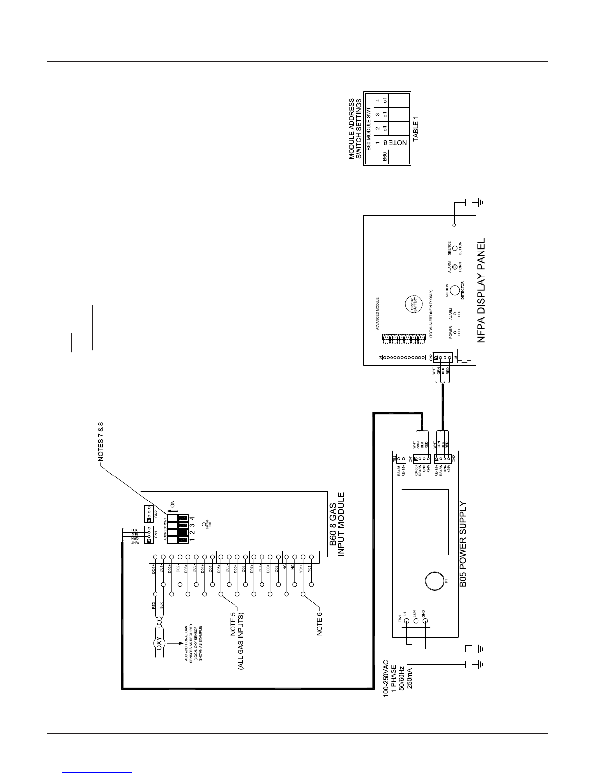
3.2 NFPA Area Wiring Diagram
MULTI-CONDUCTOR CABLE MUST BE TWISTED PAIR TYPE WITH SHIELD
Notes:
1. MAIN DISCONNECT PROVIDED BY OTHERS
2. FIELD POWER WIRING TO BE COPPER RATED FOR 75°C MINIMUM
3. FIELD SIGNAL WIRING TO BE MINIMUM 22AWG
TOTAL CIRCUIT LENGTH NOT TO EXCEED 10,000’ & MAX. 1K OHM RESIS-
TANCE
4. -- -- -- -- INDICATES FIELD WIRING OUTSIDE OF BOX.
5. SIGNAL INPUTS FROM GAS SENSOR MODULES.
6. RELAY OUTPUT CONTACT RATED 3A / 30VDC MAX.
USING TABLE 1.
7. SEE MODULE LABEL TO SET MODULE ADDRESS (POSITIONS 2,3, & 4). VERIFY
8. SET ADDRESS SWT POSITION 1 TO “ON” FOR LAST MODULE IN CHAIN ONLY.
FACTORY WIRED
CHASSIS GROUND
Figure 33: Wiring Diagram for NFPA MEGA3 Area Alarm
4107 9016 59.02
3-2
ENCLOSURE
GROUND SCREW
Page 29
MEGA3 NFPA Medical Gas Notification System
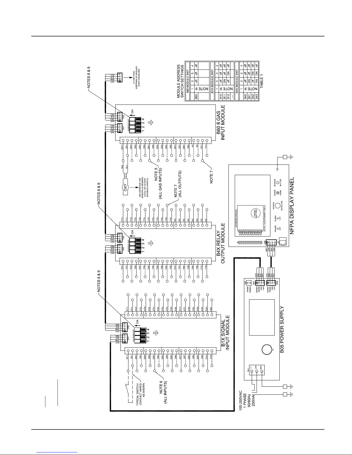
3.3 NFPA Combination Wiring Diagram
MULTI-CONDUCTOR CABLE MUST BE TWISTED PAIR TYPE WITH SHIELD
TOTAL CIRCUIT LENGTH NOT TO EXCEED 10,000’ & MAX. 1K OHM RESIS-
TANCE
EQUIPMENT OR LINE PRESSURE SWITCHES.
USING TABLE 1.
INPUT OR OUTPUT MODULES, OR BOTH.
Notes:
1. MAIN DISCONNECT PROVIDED BY OTHERS
2. FIELD POWER WIRING TO BE COPPER RATED FOR 75°C MINIMUM
3. FIELD SIGNAL WIRING TO BE MINIMUM 22AWG
4. -- -- -- -- INDICATES FIELD WIRING OUTSIDE OF BOX.
5. SIGNAL INPUTS (UP TO 8) FROM GAS SENSOR MODULES.
6. SINGAL INPUTS FROM DRY NORMALLY-CLOSED CONTACTS FROM SOURCE
7. RELAY OUTPUT CONTACT RATED 3A / 30VDC MAX.
8. SEE MODULE LABEL TO SET MODULE ADDRESS (POSITIONS 2,3, & 4). VERIFY
9. SET ADDRESS SWT POSITION 1 TO “ON” FOR LAST MODULE IN CHAIN ONLY.
10. ALARMS ARE CONFIGURATION DEPENDENT: AND MAY CONTAIN EITHER
3-3
Figure 34: Wiring Diagram for NFPA MEGA3 Combination Alarm
FACTORY WIRED
CHASSIS GROUND
ENCLOSURE
GROUND SCREW
4107 9016 59.02
Page 30

Page 31

MEGA3 NFPA Medical Gas Notification System
4.0 Operation
4.1 Overview
The MEGA3 Medical Gas Alarm is a touchscreen gas pressure and system monitoring
alarm created for ease of use.
For convenience, it is shipped from the factory as a configured unit.
4.1.2 Gas Badge
Every gas monitored by the alarm will have
a gas badge which will show the following
information:
• Gas being monitored
• Location where gas is being used
• Gas pressure value
• Gas pressure status (Low, Normal, or
High)
Figure 36: Gas Badge
Figure 35: MEGA3 Alarm Main Screen
4.1.1 Main Screen
The first screen that users see on a configured
unit is the MAIN screen. The MAIN screen
is the main view for the alarm and shows
the pressure status of all of the gases (area)
or source signals (master) the alarm is
monitoring.
NOTE:
The main screen will appear dierent depending on whether the alarm panel is configured as an area, master or combination.
An area alarm main screen will show gas
badges, a master alarm main screen will
show source signals, and a combination
alarm main screen will show both gas
badges and source signals.
4.1.3 Source Signals
Every source signal monitored by the alarm
will display the following information once
configured:
• Equipment being monitored
• Location of the source equipment
• Signal being monitored
• Source signal status Red (open - in alarm)
or Green (closed - normal).
The display can show the status of up to 40
signals. The hardware installed limits how
many of the 40 signals can be used.
4-1
Figure 37: Source Signals
4107 9016 59.03
Page 32

MEGA3 NFPA Medical Gas Notification System
5. History button. This icon button toggles
to the HISTORY screen. This screen is only
available after upgrading to a TotalAlert
Infinity™ series of alarms.
The button that corresponds to the screen
currently in use will be blue.
4.1.5 Fault Status
If a gas sensor is measuring above or below
Figure 38: Combination Alarm Main Screen
4.1.4 Toolbar
Running from left to right across the bottom
of the MAIN screen is the toolbar. The
Normal toolbar is available when the alarm is
operating in normal status and shows:
the alarm level, the high or low pressure indicator on the gas badge will flash for the gas
pressure out of range.
If a gas sensor becomes disconnected or
shorted, both high and low indicators for
that gas will flash and an error code and message will be displayed.
Home
Alarm Status (normal)
Button Location of Panel
Figure 39: Normal Toolbar
To switch to the Icon toolbar, touch the
HOME button.
Home Button Information Button
Alarm
Button
Configuration
Button
History Button
Figure 40: Icon Toolbar
Icons on the toolbar:
1. Home button. This icon button toggles to
the MAIN screen.
2. Alarm button. This icon button toggles to
the ACTIVE ALARM screen.
If a configured source signal becomes an
open circuit and the source badge and the
signal status will change from green to blinking red.
The Icon toolbar will appear, and the Alarm
button will be flashing red. By default the
screen will change to the Active Alarm
Screen.
Alarm Button (Red)
Figure 41: Fault Status
NOTE:
The Normal toolbar will automatically
reappear when all faults are resolved.
Users can touch any flashing red light to go to
the ACTIVE ALARM screen.
3. Configuration button. This icon button
toggles to the CONFIGURATION screen.
4. Information button. This icon button
toggles to the INFORMATION screen.
4107 9016 59.03
4-2
Page 33

MEGA3 NFPA Medical Gas Notification System
4.1.6 Display Screens
Active Alarm Screen
The ACTIVE ALARM screen provides detailed
information about pressures or signals that
are in alarm condition.
Gas LocationGas Type Gas Pressure
Area Alarm
Master Alarm
Figure 42: Active Alarm Screen
Configuration Screen
The CONFIGURATION screen is used to configure the alarm. The configuration screen is
only accessible with a password. It is divided
into three parts.
The top left section is the Display section. It
contains a small representative view of the
MAIN screen and buttons for configuring the
MAIN screen.
The top right section is the Settings section.
Tabs not accessible are grayed out.
Information Screen
The INFORMATION screen provides pertinent
information about the alarm — including high
and low alarm values and firmware details —
in one central place.
Figure 44: Information Screen
Version Tab
Touch the VERSION tab to view details about
the:
• Series, code, and style of the alarm
• Firmware version for the main display
board and additional boards
The bottom section is the Icon toolbar.
Display
Icon Toolbar
Figure 43: Configuration Screen
Settings
Figure 45: Version Tab
NOTE:
The version screens automatically scroll.
Touch the blinking up or down arrow in the
lower right to stop the automatic scroll and
start the manual scroll.
4-3
4107 9016 59.03
Page 34

MEGA3 NFPA Medical Gas Notification System
Touch the X button in the upper right to
close and return to the INFORMATION
screen.
Alarm Points Tab
Touch the ALARM POINTS tab for a quick
view of the alarm points—the low and high
set points—for each gas badge (area alarm) or
source signal configuration (master alarm).
Area Alarm
Test Alarm Tab
Touch the TEST ALARM tab to run a quick test
of the hardware.
The audible alarm will sound for one-to-two
seconds to test that the horn is working properly.
The LEDs on the front of the alarm will illuminate as well to show that they are still
functioning.
Warnings Tab
Touch the WARNINGS tab to view any possible active warnings that would include lost
network communication with manually enrolled devices, lost connection to a connected/initialized board, or when a master signal
input is wired, but not assigned/programmed
to an alarm sign.
Master Alarm
Figure 46: Alarm Points Tab
This screen provides a complete view of the
configuration and is a fast way to check items
such as:
• Location where the pressure sensors and
source signals are physically wired.
• Gases Monitored
• Areas Monitored
• Low and high pressure set points for area
signals
• Source Signals Monitored
Touch the X button in the upper right to
close and return to the INFORMATION
screen.
Figure 47: Warnings Tab
History Screen
NOTE:
This feature is only available in the
TotalAlert Infinity™ series of alarms.
4107 9016 59.03
Figure 48: History Screen
4-4
Page 35

MEGA3 NFPA Medical Gas Notification System
4.2 Alarm Configuration
To set up or change the configuration of an
alarm, start on the CONFIGURATION screen.
Users are always prompted to enter the password when accessing this screen.
Close
Clear all
entered
text
EnterBackspace
Figure 49: Password entry
Type the default password (121212), and
touch the Enter button. You will be prompted
to change the password if not done so previously (Figure 49).
Figure 51: Normal Status Message screen
Figure 50: Configuration Screen
The CONFIGURATION screen displays.
Normal Status Message/Panel ID Description
The MEGA3 alarm allows for customization of
certain labels and messages.
Normal Status Message
To change the message that is communicated
when the alarm is operating in normal status:
1. Touch the [A] button that is located to the
left of the configuration screen (Figure 50).
2. Touch the Erase button on the keyboard
to delete the existing message (Figure 51).
3. Enter the new word or message.
4. Touch the Save button.
4-5
4107 9016 59.03
Page 36

MEGA3 NFPA Medical Gas Notification System
Figure 52: Panel ID Description screen
Panel ID Description
Figure 53: Area Alarm User Interface
To change the description of the location of
the alarm panel:
1. Touch the [B] button that is located to the
right of the configuration screen (Figure
50).
2. Touch the Erase button on the keyboard
to delete the existing description (Figure
52).
3. Enter the new description.
4. Touch the Save button.
4.3 Setting Up an Area Alarm
4.3.1 Configuring Gas Badges
The MEGA3 area alarm is designed to allow
configuration of eight gas badges using the
B60 board.
To configure the first badge to custom settings, touch the [1] button on the configuration screen (Figure 50).
4107 9016 59.03
4-6
Page 37

MEGA3 NFPA Medical Gas Notification System
Eight tabs are used for configuration (Figure 54). Tabs are listed in alphabetical order.
A = [GAS INPUT]
B = GAS DESC
C = [GAS NAME]
D = AREA MONITORED
E = [UNITS OF MEASURE]
F = LOW ALARM SETTINGS
G = HIGH ALARM SETTINGS
H = ZERO OFFSET
To change which wired input should be shown on the badge
To change color codes based on standard and country
To label the gas
To edit the location label for a specific gas
To change the displayed unit of measure for the pressure/vacuum
To adjust the value that should indicate that the pressure is low
To adjust the value that should indicate that the pressure is high
To make small adjustments to the displayed pressure based on user
preference
B = Gas Desc Tab
Figure 54: Configuring Gas Badges
A = [Gas Input] Tab
Figure 55: Gas Input Tab
To change which wired sensor should be displayed on that badge:
1. Touch the tab for the appropriate wired
gas sensor.
Figure 56: Gas Desc Tab
To change color codes based on your standard and country:
1. Scroll through the codes using the right
and left arrows at the bottom of the
screen.
2. Touch the tab for the appropriate code.
3. Touch the Save button when you see a
check beside your selection.
Note: If the alarm default is correct, touch
the X button in the upper right to close the
screen.
2. Touch the Save button to close the screen.
4-7
4107 9016 59.03
Page 38

MEGA3 NFPA Medical Gas Notification System
C = [Gas Name] Tab
Figure 57: Gas Name Tab
Use the keyboard to change the gas name.
Touch the [<ÁÑ] to toggle to symbols and extended Latin Characters. Touch the [1AZ] key
to toggle back to letters and numbers.
D = Area Monitored Tab
E = [Units of Measure] Tab
Figure 59: Units of Measure Tab
To change the unit of measure:
1. Touch the tab for the appropriate unit of
measure.
2. Touch the Save button to close the screen.
F = Low Alarm Settings Tab
Figure 58: Area Monitored Tab
To add locations to be monitored:
1. Touch an unused location tab.
2. Using the keyboard, enter the name of the
location that you would like to monitor
(e.g., ROOM 1). Enter multiple locations
as needed (e.g., Room 1, Room 2, Room
5).
3. A check appears when the location is selected, the save button has to be pressed
if the selection is new.
To edit the location information, touch the
Pencil button.
4107 9016 59.03
Figure 60: Low Alarm Settings Tab
You can remove the low alarm set point or
customize the low alarm set point.
To remove the low alarm set point:
1. Touch the NONE tab.
2. Touch the check on the CONFIRM SETTINGS CHANGE screen.
To customize the low alarm set point:
1. Touch the ADJUST tab.
2. Enter the new set point.
3. Touch the Save button.
4-8
Page 39

MEGA3 NFPA Medical Gas Notification System
G = High Alarm Settings Tab
Figure 61: High Alarm Settings Tab
You can remove the high alarm set point or
customize the high alarm set point.
To remove the high alarm set point:
1. Touch the NONE tab.
2. Touch the check on the CONFIRM SETTINGS CHANGE screen.
To customize the high alarm set point:
H = Zero Oset Tab
Figure 62: Zero Oset Tab
In some cases, facility dial gauges may show
slightly dierent readings than the MEGA3
alarm (e.g., 46 PSI versus 44 PSI). To match
the MEGA3 alarm exactly to a facility dial
gauge:
1. Select the oset amount.
2. Touch the Save button to close the screen.
1. Touch the ADJUST tab.
2. Enter the new set point.
3. Touch the Save button.
Configuring Additional Gas Badges
Configure additional gas badges by touching
the number on the main configuration screen
that corresponds with the gas badge and
repeating the steps listed above.
4-9
4107 9016 59.03
Page 40

MEGA3 NFPA Medical Gas Notification System
4.3.2 Initial Setup for an Unconfigured Area Alarm
The SETUP INFORMATION screen is the first
screen that users will see on an unconfigured
alarm. (The MAIN screen is the first screen
that users will see on a configured alarm.)
Password Setup - Unconfigured Alarm
• Touch the Configuration button.
Configuration
Button
Figure 63: Setup Information Screen
Entering the Password
Note:
If you would like to change the password,
touch Change Password. Enter a 4-10 digit
password, and touch the Enter button. Confirm the new password. Touch the X button
in the upper right to close the SECURITY
PASSWORD screen.
Figure 65: Changing the Security Password
• The CONFIGURATION screen will display
as unconfigured and ready for setup.
The ENTER SECURITY PASSWORD screen appears.
Figure 64: Entering the Security Password
• Enter the security password. (The default
password is 121212.)
• Touch the Enter button.
• Touch Continue to advance to the
CONFIGURATION screen.
Figure 66: Unconfigured Configuration Screen
4107 9016 59.03
4-10
Page 41

MEGA3 NFPA Medical Gas Notification System
Primary Settings Tab
The PRIMARY SETTINGS tab allows you to
select the alarm type, initialize boards, and
select gas inputs.
• Touch the PRIMARY SETTINGS tab
Alarm Type Tab
The ALARM TYPE screen defines which type
of alarm will be displayed and drives later
setup functions.
Initialize Modules Tab
The PRIMARY SETTINGS screen will now
display with ALARM TYPE checked, INITIALIZE
MODULES active, and the other tabs grayed
out.
Figure 69: Initialize Modules Tab
• Touch the INITIALIZE MODULES tab.
The INITIALIZE MODULES screen is used to set
up the boards that are installed. The boards
function as the input/output hardware of the
alarm.
Figure 67: Alarm Type Tab
• Touch the ALARM TYPE tab.
• Choose a code style based on code requirements.
Save
Erase
Figure 68: Choosing Code and Alarm Styles
• Touch the AREA tab
• Touch the Save button when you see
checks beside your selections to save the
settings and return to the PRIMARY SETTINGS screen.
Note: To clear your selections, touch the
Erase button.
Figure 70: Initialize Modules Screen
4-11
4107 9016 59.03
Page 42

MEGA3 NFPA Medical Gas Notification System
At this point, you have two options:
1. Either touch the Scan button to prompt
the alarm to autofill the screen for you.
OR
2. Complete the screen by selecting the
boards installed in the alarm.
Figure 71: B60 board selected
Note:
• Touch the GAS SENSORS tab.
Figure 73: Gas Input Screen
Users may select up to eight dierent gases
on the GAS INPUT screen. These gases correspond to the digital gas sensors wired into
the GAS INPUT / B60 board (see section
2.4.2).
• To select the first gas, touch the D01 =
NONE/BLANK tab.
THE GAS INPUT / B60 board must be selected during the configuration of an area alarm.
• Touch the Save button when you see
checks beside your selections.
Gas Sensors Tab
The PRIMARY SETTINGS screen will now display with ALARM TYPE and INITIALIZE MODULES checked, GAS SENSORS active, and the
last tab grayed out.
Figure 74: Gas Sensors Screen
• Touch the right and left arrows at the
bottom of the screen to scroll through
additional gas choices, including options
to create custom mixes. Select the gas that
is wired into the D01 input on the GAS
INPUT / B60 board.
Figure 72: Gas Sensors Tab
4107 9016 59.03
4-12
Page 43

MEGA3 NFPA Medical Gas Notification System
4.4 Setting Up a Master Alarm
The master alarm monitors whether source
equipment is working properly. Two independent hard wired alarms are required per facility to meet the 24-hour monitoring requirement in the NFPA 99 standard.
The information for the signals connected in
the field needs to be entered into the alarm
using the touch screen interface.
Figure 75: Gas Choices
• Touch the Save button when you see a
check beside your selection.
• (If an alarm sounds, press the Mute button on the panel under the screen and
continue with setup.)
• Repeat to add additional gases.
• Touch the X button in the upper right to
close the GAS SENSORS screen and return
to the PRIMARY SETTINGS screen. The
alarm will retain your information.
• Touch the X button in the upper right to
close the PRIMARY SETTINGS screen. The
alarm will retain your information.
Figure 76: Master Alarm User Interface
To set up or change the configuration of an
alarm, follow the steps outlined in the initial
set-up for an unconfigured master alarm in
section 4.4.
4-13
4107 9016 59.03
Page 44
MEGA3 NFPA Medical Gas Notification System
4.4.1 Configuring Source Badges
The MEGA3 alarm is designed to allow
the setup and monitoring of 4 source
badges. Each source badge has room for
10 source signal inputs (A-K) (Figure 78).
Four tabs are used for the detailed configuration of each source signal input.
Note:
Maximum wired input signals allowed is 40.
1 = ALARM POINT
2 = GAS MONITORED
3 = SIGNAL SETTINGS
4 = LOCATION
To identify the location
where the wires are
landed
To choose the gas to be
monitored
To select source signal
description
To add a location for
the source signal
The four tabs for each source signal input are
grouped together and named alphabetically
(e.g., A1, A2, A3, A4 / B1, B2, B3, B4 / C1, C2,
C3, C4 / etc.).
Users can scroll to the first tab for each source
signal input by using the right and left arrows at the bottom of the screen. Or, to
jump quickly to the first tab, simply touch
the letter button on the grid on the left that
corresponds to the source signal input (A-K)
(Figure 78).
Figure 77: Configuration Screen
To configure alarm points in the first badge,
touch the [1] button in the numeric display.
Tabs used for configuration
of source signal input A
Source
signal
inputs
Figure 78: Configuration of alarm points
The first tab for each source signal input is
highlighted and the remainder grayed out
to ensure that users complete the setup in
the correct order. The other three tabs will
become available to you as you advance
through setup.
4107 9016 59.03
4-14
Page 45

MEGA3 NFPA Medical Gas Notification System
A1 = Alarm Point Tab
Figure 79: Alarm Point Tab
To identify the location where the wires are
landed:
1. Touch the tab for the appropriate board
and terminal block. Ex: B10 board, X01
Terminal Block
2. Touch the Save button when you see a
check beside your selection to go automatically to the GAS MONITORED screen.
A2 = Gas Monitored Tab
A3 = Signal Settings Tab
Figure 81: Signal Settings Tab
To select source signal input text:
1. Touch the NONE/BLANK tab.
2. Scroll through the options using the
right and left arrows at the bottom of the
screen.
3. Touch the tab for the appropriate option
4. Touch the Save button when you see a
check beside your selection to save the
selection and return to the SIGNAL SETTINGS screen.
Figure 80: Gas Monitored Tab
To choose the gas to be monitored:
1. Scroll through the codes using the right
and left arrows at the bottom of the
screen.
2. Touch the tab for the appropriate gas.
3. Touch the Save button when you see a
check beside your selection to go automatically to the SIGNAL SETTINGS screen.
5. Touch the X button in the upper right to
go automatically to the LOCATION screen.
4-15
4107 9016 59.03
Page 46

MEGA3 NFPA Medical Gas Notification System
A4 = Locations Tab
Figure 82: Locations Tab
To add source locations being monitored:
1. Touch a blank location tab.
2. Using the keyboard, enter the name of the
location for the source equipment being
monitored (e.g., ROOM 1). Enter multiple
locations as needed (e.g., Manifold Room,
Roof Top, Source Room).
4.4.2 Initial Setup of an Unconfigured Master Alarm
The SETUP INFORMATION screen is the first
screen that users will see on an unconfigured
alarm.
(The MAIN screen is the first screen that users
will see on a configured alarm).
Configuration
Button
Figure 83: Setup Information Screen
3. Touch the Save button to close the screen
and return to the SOURCE LOCATION
screen.
4. Make sure the location you selected is
highlighted in green, and touch the save
button in the upper right to save and return to the CONFIGURE (SOURCE) screen.
Note: To edit the location information, touch
the Pencil button.
Configuring Additional Source Badges
Configure alarm points on additional source
badges by touching the number on the
numeric display that corresponds with the
source badge and repeating the steps listed
above.
• Touch the Configuration button.
Entering the Password
The ENTER SECURITY PASSWORD screen appears.
Figure 84: Entering the Security Password
• Enter the security password. (The default
password is 121212.)
• Touch the Enter button.
• Touch Continue to advance to the
CONFIGURATION screen.
4107 9016 59.03
4-16
Page 47

MEGA3 NFPA Medical Gas Notification System
Note:
If you would like to change the password,
touch Change Password. Enter a 4-10 digit
password, and touch the Enter button. Confirm the new password. Touch the X button
in the upper right to close the SECURITY
PASSWORD screen.
Figure 85: Changing the Security Password
• The CONFIGURATION screen will display
as unconfigured and ready for setup
Alarm Type Tab
The ALARM TYPE screen defines which type
of alarm will be displayed and drives later
setup functions.
• Touch the ALARM TYPE tab.
Figure 86: Alarm Type Tab
• Choose a code style based on code requirements.
• Touch the MASTER tab.
Primary Settings Tab
The PRIMARY SETTINGS tab allows you to
select the alarm type and initialize boards.
• Touch the PRIMARY SETTINGS tab.
Save
Erase
Figure 87: Choosing Code and Alarm Styles
• Touch the Save button when you see
checks beside your selections to close the
screen and return to the PRIMARY SETTINGS screen.
Note: To clear your selections, touch the
Erase button.
4-17
4107 9016 59.03
Page 48

MEGA3 NFPA Medical Gas Notification System
Initialize Modules Tab
The PRIMARY SETTINGS screen will now display with ALARM TYPE checked and INITIALIZE MODULES active.
• Touch the INITIALIZE MODULES tab.
The INITIALIZE MODULES screen is used to set
up the boards that are installed. The boards
function as the input/output hardware of the
alarm.
4.5 Setting Up a Combination Alarm
The combination alarm combines the functionality of an area alarm and a master alarm.
It monitors two things:
• Gases and their pressures.
• Source equipment.
Two independent hard wired alarms monitor-
ing source equipment are required per facility
to meet the 24-hour monitoring requirement
in the NFPA 99 standard.
For convenience to the customer, the MEGA3
Medical Gas Alarm is shipped from the factory as a configured unit. However, the information for the signals connected in the field
need to be entered into the alarm using the
touch screen interface.
Figure 88: Initialize Modules Screen
At this point, you have two options:
1. Either touch the Scan button to prompt
the alarm to autofill the screen for you.
OR
2. Complete the screen by selecting the
boards installed in the alarm.
Touch the Save button when you see checks
beside your selections.
The PRIMARY SETTINGS screen will now display with ALARM TYPE and INITIALIZE MODULES highlighted and checked and the other
tabs grayed out.
• Touch the X button in the upper right to
close and return to the CONFIGURATION
screen.
Figure 89: Combination Alarm User Interface
4.5.1 Configuring Source Badges
• Follow the steps for configuring source
badges on a master alarm (section 4.4.1).
4.5.2 Configuring Gas Badges
• Follow the steps for configuring gas badges on an area alarm (section 4.3.1).
4107 9016 59.03
4-18
Page 49

MEGA3 NFPA Medical Gas Notification System
4.5.3 Initial Setup of an Unconfigured Combination Alarm
The SETUP INFORMATION screen is the first
screen that users will see on an unconfigured
alarm.
(The MAIN screen is the first screen that users
will see on a configured alarm).
Configuration
Button
Figure 90: Setup Information Screen
• Touch the Configuration button.
Entering the Password
The ENTER SECURITY PASSWORD screen appears.
Enter the security password. (The default
password is 121212.)
• Touch the Enter button.
• Touch Continue to advance to the
CONFIGURATION screen.
Figure 92: Changing the Security Password
Note:
If you would like to change the password,
touch Change Password. Enter a 4-10 digit
password, and touch the Enter button. Confirm the new password. Touch the X button
in the upper right to close the SECURITY
PASSWORD screen.
• The CONFIGURATION screen will display
as unconfigured and ready for setup.
Figure 91: Entering the Security Password
Primary Settings Tab
The PRIMARY SETTINGS tab allows you to
select the alarm type and initialize boards.
• Touch the PRIMARY SETTINGS tab.
4-19
4107 9016 59.03
Page 50

MEGA3 NFPA Medical Gas Notification System
Alarm Type Tab
The ALARM TYPE screen defines which type
of alarm will be displayed and drives later
setup functions.
• Touch the ALARM TYPE tab.
Figure 93: Alarm Type Tab
• Choose a code style based on code requirements.
• Touch the COMBO tab.
Initialize Modules Tab
The PRIMARY SETTINGS screen will now display with ALARM TYPE checked and INITIALIZE MODULES active.
• Touch the INITIALIZE MODULES tab.
The INITIALIZE MODULES screen is used to set
up the boards that are installed. The boards
function as the input/output hardware of the
alarm.
Save
Erase
Figure 94: Choosing Code and Alarm Styles
• Once the desired tabs are selected, touch
the Save button to save the selection an
go back to the PRIMARY SETTINGS screen.
Note: To clear your selections, touch the
Erase button.
Figure 95: Initialize Modules Screen
At this point, you have two options:
1. Either touch the Scan button to prompt
the alarm to autofill the screen for you.
OR
2. Complete the screen by selecting the
boards installed in the alarm.
Touch the Save button when you see checks
beside your selections.
4107 9016 59.03
4-20
Page 51

MEGA3 NFPA Medical Gas Notification System
Gas Sensors Tab
The PRIMARY SETTINGS screen will now display with ALARM TYPE and INITIALIZE MODULES checked, GAS SENSORS active, and the
last tab grayed out.
• Touch the GAS SENSORS tab
B60 Board
Users may select up to six dierent gases
on the GAS INPUT screen. These gases correspond to the digital gas sensors wired into
the GAS INPUT / B60 board.
Note: This setup accommodates:
• Three source badges (10 signals each)
and two gas badges = five total badges
• Two source badges (10 signals each) and
four gas badges = six total badges
• One source badge (10 signals) and six gas
badges = seven total badges
• Touch the Save button when you see a
check beside your selection. (If an alarm
sounds, press the Mute button on the
panel under the screen and continue with
setup).
• Repeat to add additional gases.
• Touch the X button in the upper right to
close the GAS SENSORS screen and return
to the PRIMARY SETTINGS screen. The
alarm will retain your information.
•
B65 Board
The GAS SENSORS screen defaults to the B60
board, so users will see a MODULE NOT INITIALIZED message.
• To select the first gas, touch the
D01=NONE/BLANK tab.
• Touch the right and left arrows at the
bottom of the screen to scroll through
additional gas choices, including options
to create custom mixes. Select the gas that
is wired into the D01 input on the GAS
INPUT / B60 board.
Figure 96: Gas Choices
Figure 97: B60 Module not initialized
• Touch the B65 tab to go to the GAS COMBO screen.
4-21
4107 9016 59.03
Page 52

MEGA3 NFPA Medical Gas Notification System
Users may select up to three dierent gases
on the GAS COMBINATION screen. These gases correspond to the digital gas sensors wired
into the GAS COMBINATION / B65 board.
Note: This setup accommodates:
• 10 Source Inputs
• 3 Gas Sensors
• 6 Relay Outputs
• To select the first gas, touch the
D01=NONE/BLANK tab.
• Use the right and left arrows at the bottom of the screen to scroll through additional gas choices, including options to
create custom mixes. Select the gas that
is wired into the D01 input on the GAS
COMBINATION / B65 board.
• Touch the Save button when you see a
check beside your selection. (If an alarm
sounds, press the Mute button on the
panel under the screen and continue with
setup).
• The GAS COMBINATION screen will now
display with the D01=[X] checked
4.5.4 Miscellaneous Tab
Users can customize certain aspects of the
MEGA3 Alarm’s appearance and functionality.
Aspects of functionality that can be adjusted
include the date and time settings.
• Touch the MISCELLANEOUS tab.
Figure 99: Miscellaneous Screen
Figure 98: B65 screen
• Repeat the above steps to select up to two
additional gases.
4107 9016 59.03
4-22
Page 53

MEGA3 NFPA Medical Gas Notification System
4.6 Additional Components
4.6.1 4-20mA Devices
To configure a 4-20mA device for monitoring,
start on the CONFIGURATION screen. Users
are always prompted to enter the password
when accessing this screen.
Type the password, and touch the Enter button.
The CONFIGURATION screen displays.
Figure 100: Configuration screen
The MEGA3 alarm is designed to allow configuration of four gas badges using the B50
board to monitor 4-20mA devices. The alarm
must be set as an Area panel or Combination
panel. See Alarm Type Tab in Section 4.3.2.
Press the “Scan” button to make sure the B50
board is set up, as it should turn green. Once
the B50 board is green, press the “Save” icon
to exit the screen. Exit the “Primary Settings”
screen.
Figure 102: initialize Modules screen
To configure the first badge to custom settings, touch the corresponding number button in the numeric display that represents
the badge to be configured. If a badge needs
to be added, press the “+” for additional
badges.
Eight tabs are used for configuration. Tabs are
listed in alphabetical order (Figure 103).
Figure 101: Primary Settings screen
After configuring the Alarm Type, the B50
board must be initialized. Select “Initialize
Modules” on the Primary Settings Screen.
Figure 103: Configure Area screen
A = [Gas Input] Tab
The B50 should be green and there should be
4 choices (I01, I02, I03, I04). Select the wired
input to be displayed on that badge:
Touch the tab for the appropriate wired gas
sensor.
4-23
4107 9016 59.03
Page 54

MEGA3 NFPA Medical Gas Notification System
Figure 104: B50 Tab, 4-20 mA
Touch the Save button to close the screen.
B = Gas Desc Tab
To assign a color code for the device:
1. Scroll through the codes using the right
and left arrows at the bottom of the
screen. Custom colors are located on
pages 7-8.
2. Touch the tab for the appropriate code.
3. Touch the Save button when you see a
check beside your selection.
Figure 106: Gas Text Keyboard
D = Area Monitored Tab
To add locations to be monitored:
1. Touch an unused location tab.
2. Using the keyboard, enter the name of the
location that you would like to monitor
(e.g., ROOM 1). Enter multiple locations
as needed (e.g., Room 1, Room 2, Room
5).
3. A check appears when the location is selected, the save button has to be pressed
if the selection is new.
To edit the location information, touch the
Pencil button.
Figure 105: Gas Color Code Tab
C = [Gas Name] Tab
Use the keyboard to assign a device name.
Type in the name of the device to be monitored. Touch the [<ÁÑ] to toggle to symbols
and extended Latin Characters. Touch the
[1AZ] key to toggle back to letters and numbers.
Touch the Save button when complete.
4107 9016 59.03
Figure 107: Source Location
E = [Units of Measure] Tab
To set up the 4-20mA device:
1. Touch the tab for “4MA=” to set the low
measurement point of the device (zero
for example) and press the save button to
exit.
4-24
Page 55

MEGA3 NFPA Medical Gas Notification System
1. Touch the tab for “20MA=” to set the high
measurement point of the device (100
for example) and press the save button to
exit.
2. Touch the tab for “Units=” to set the
method of measurement (percent for
example), type in the measurement type
and press the save button to exit.
3. Touch the X button in the upper right to
close the screen.
G = High Alarm Settings Tab
You can remove the high alarm set point or
customize the high alarm set point.
To remove the high alarm set point:
Figure 109: Low Alarm Settings
Figure 108: Units of Measure Tab
F = Low Alarm Settings Tab
You can remove the low alarm set point or
customize the low alarm set point.
To remove the low alarm set point:
1. Touch the NONE tab.
2. Touch the check on the CONFIRM SETTINGS CHANGE screen.
To customize the low alarm set point:
1. Touch the ADJUST tab.
2. Enter the new set point.
3. Touch the Save button.
1. Touch the NONE tab.
2. Touch the check on the CONFIRM SETTINGS CHANGE screen.
To customize the high alarm set point:
1. Touch the ADJUST tab.
2. Enter the new set point.
3. Touch the Save button.
Configuring Additional 4-20mA Devices
Configure additional 4-20mA devices by
touching the number on the numeric display
that corresponds with the gas badge and
repeating the steps listed above.
4-25
4107 9016 59.03
Page 56

MEGA3 NFPA Medical Gas Notification System
4.6.2 Relay Output Board (B4X
Board)
To configure a Relay Output, start on the
CONFIGURATION screen. Users are always
prompted to enter the password when accessing this screen.
Type the password, and touch the Enter button.
The CONFIGURATION screen displays.
The next step is to select the “Relay Outputs”
from the menu on the Configuration Screen.
The B40 board should be highlighted in
Green (or other Relay Output board installed
in the rough-in box).
Select the signal that corresponds to the
output wires on the relay board (Y01 for
example).
Figure 112: Relay Outputs Screen
Figure 110: Configuration Screen
The B40 (or B41, B42, B43) board must be
initialized. Touch Primary Settings from the
right side menu, then select “Initialize Modules”. Press the “Scan” button to make sure
the B40 board is set up, as it should turn
green. Once the B40 board is green, press the
“Save” icon to exit the screen. Exit the “Primary Settings” screen.
After selecting the signal, you will need to
assign it to an alarm signal to send. Select
“Wired” on the Relay Output screen if the
signal to be relayed is wired into the rough-in
box.
Figure 113: Relay Output Signal
There are four choices for the relay output
signal.
Figure 111: Initialize Modules Screen
4107 9016 59.03
4-26
Page 57

MEGA3 NFPA Medical Gas Notification System
3. “Many Signals” allows the user to group
multiple signals on a single relay output.
If any of the signals goes into alarm condition, the relay output will report an alarm
condition. Press “Many Signals” to move
to the Relay Output screen and select
from 1 to 10 signals to group together.
Select the number 01 to start, then select
the first signal to be grouped by pressing
the corresponding number on the Relay
Output (such as X01 from the B10 board).
Figure 114: Relay Output Signals Screen
1. A single “Any Fault” which will report a
general alarm fault if any of the alarm
signals on the alarm go into alarm condition. To select “Any Fault”, press the blue
“Any Fault” to change it to green with the
check mark. Then press Save to return
to Relay Outputs and set up additional
outputs.
Press Save to return to the Many Signal Relay Output screen. Next select 02 to capture the second signal to be monitored.
Repeat up to a grouping of 10 signals.
2. “One Signal” reports a single signal
through the relay output. When pressing
“One Signal,” the next step is to assign
the signal to be transmitted. On the Relay
Output screen, select the Input Signal to
be transmitted (X01 from the B10 board
for example). Press Save to return to the
Relay Outputs screen.
Figure 115: Relay Output One Signal
Figure 116: Relay Output Many Signals
4. “Gas Sensor Alarm Fault” allows the user
to report a fault condition based on a gas
sensor through the relay output. When
choosing Gas Sensor Alarm Fault, select
the gas sensor to be monitored from the
list. Press Save to return to the Relay Outputs screen.
4-27
Figure 117: Gas Sensor Alarm Fault
4107 9016 59.03
Page 58

Page 59
MEGA3 NFPA Medical Gas Notification System
5.0 Retrofit
Retrofit Kits Include:
Figure 118: TA2/MEGA2/Others 8-Gas Trim Kit
4107 2206 15 Contents
Qty Description
1 Trim Plate Retrofit 16x27
1 Adapter Bracket, Power Supply
2-Position
4 Hardware #6-32 x 1/4” long Pan Head Ma-
chine screw
5.1 Retrofit of TotalAlert2 Area Alarm
Panel (4-gas, 8-gas) and MEGA2
Alarms
NOTE: The existing Digital Gas Sensors will
be reused for the new alarm.
5.1.1 Remove Components from
Existing Alarm
1. Open old alarm panel to be retrofitted
and ensure that the retrofit kit to be installed is correct according to the number
of Signal Inputs, Relay outputs, and/or
Gas Sensor signals (See Appendix A).
2. Ensure that you have the additional trim
kit if retrofitting a TotalAlert2/MEGA2,
8-Gas alarm (4107220615).
3. Test Master alarm signals to validate wiring and document all signal wires coming
into the box with alarm type and locations prior to disconnecting the front
panel. This information will be required
to setup the new alarm.
4. Turn o the supply power to the alarm.
Figure 119: TotalAlert1 Trim Kit
4107 2206 16 Contents
Qty Description
1 Trim Plate Retrofit TotalAlert1 Single
1
1 Trim Plate Retrofit TotalAlert
1 Adapter Bracket, Power Supply
1 Adapter Bracket, I/O Modules
4 Hardware #6-32 x 1/4” long Pan Head Ma-
chine screw
NOTE: Due to the nature of retrofit installations,
you will have parts left over when finished.
Double
CAUTION: Verify that power has been
turned o prior to working on the alarm.
5. Remove and discard the front panel from
the existing alarm.
6. Remove the old power supply
5-1
4107 9016 59.03
Page 60

MEGA3 NFPA Medical Gas Notification System
5.1.2 Install New Power Supply
Mega Master / Area 4 Gas
a. Install the metal stando bracket that
is included with the retrofit kit onto the
studs the power supply was removed
from.
b. Mount the new Power Supply (B05)
to the bracket using the nuts provided
(Figure 120).
Power
Supply
Additional
I/O Module
Figure 120: Power Supply, Module Mounting
Power
Supply
Mounting
Bracket
TA2/MEGA2 Area 8 Gas
a. Install the 2 position metal stando
bracket that is included with the additional trim kit onto the studs the power
supply was removed from (Figure 121).
b. Mount the new Power Supply (B05)
and the B60 gas input board to the
bracket using the nuts provided with
the modules.
B60
Module
Figure 121: Power Supply, Module Mounting
Mounting
Bracket
1. Locate the Ground cable attached to the
power supply and connect the ring terminal end to the rough-in box for chassis
ground. Use the self-drilling screw provided.
2. Remove the 4 corner screws from the
power supply cover and remove the cover.
3. Connect the supply power Line and Neutral wires to the terminal block.
4. Connect the supply power Ground wire
directly to the rough-in box.
5. Replace the power supply cover and
screws.
4107 9016 59.03
5-2
Page 61

MEGA3 NFPA Medical Gas Notification System
5.1.3 Install New Components
1. Determine the best placement of the remaining I/O modules inside of the roughin box.
NOTE: I/O Modules and Power Supply will
need to be daisy chain connected via the
grey cables supplied with each I/O module.
2. Mount the I/O Modules inside the rough-
in box using the supplied hardware.
3. Connect the grey cable(s) provided; from
the power supply to the white sockets on
the I/O modules in a daisy chain manner
(Figure 122).
Figure 122: Daisy Chain of Power Supply
4. The last module in the chain needs to
have the #1 DIP switch set to “ON” (Figure 123). Refer to the module ID label.
5.1.4 Install Trim Plate
MEGA Master / Area 4 Gas
a. Install trim plate assembly to rough-in
box using the provided screws and/or
drywall anchors. Slots in the trim plate
will align with existing holes in the
rough-in box flanges (Figure 124).
NOTE: Trim ring portion can be removed
from the trim plate if the surrounding wall
area is in good condition. Mounting of the
trim ring only to the rough-in box will result
in a cleaner retrofit installation.
TA2/MEGA2 Area 8 Gas
a. Remove the trim ring from the standard
trim plate and install the wide 27” wide
x 16” tall trim plate from retrofit option
kit (4107220615). Screws are provided
in the option kit for attaching the trim
ring to the trim plate (Figure 124).
b. Install trim plate assembly to rough-in
box using the provided screws and/or
drywall anchors. Slots in the trim plate
will align with existing holes in the
rough-in box flanges.
Trim Plate
Figure 123: DIP Switch Setting
5. Connect all input signal / output signal /
gas sensor wiring to their respective modules. Refer to the wiring diagram on the
Quick Setup Guide for instructions.
5-3
Trim Ring
Figure 124: Retrofit Area Trim Panel
4107 9016 59.03
Page 62

MEGA3 NFPA Medical Gas Notification System
1. Mount the Front Panel assembly to the
trim ring using the countersink sheet
metal screws provided on the trim ring
(Figure 125).
2. Connect the lanyard to the threaded extension on the right side of the trim ring.
3. Connect the grey cable from the Front
Panel to the other white socket on the
Power Supply board.
4. Connect the ground cable from the Front
Panel to the rough-in box using the provided self-drilling screw.
5. Turn on the supply power to the alarm
and wait for the alarm to boot up.
6. Setup the new alarm by referring to the
Quick Setup guide.
5.2 Retrofit of TotalAlert1 Alarm
Panels
5.2.1 Remove Components from Existing Alarm
1. Open old alarm panel to be retrofitted
and ensure that the retrofit kit to be installed is correct according to the number
of Signal Inputs, Relay outputs, and/or
Gas Sensor signals (See Appendix A).
2. Ensure that you have the additional trim
kit for retrofitting a TotalAlert1 Single or
Double alarm panel (4107220616).
3. Test Master alarm signals to validate wiring and document all signal wires coming
into the box with alarm type and locations
prior to disconnecting the front panel.
This information will be required to setup
the new alarm.
4. Turn o the supply power to the alarm.
Figure 125: Front Panel Assembly Mounting
CAUTION: Verify that power has been
turned o prior to working on the alarm.
5. Remove and discard the front panel from
the existing alarm. For TotalAlert1 Double,
remove the door from the hinges, remove
the lock set and set aside, and discard the
door.
NOTE: For TotalAlert1 alarms, all internal
components will need to be removed and
replaced with new components.
6. Remove and discard of all the components
from the alarm rough-in box.
7. Ensure that no low voltage signal wiring is
pulled through the input power knockouts
inside of the rough-in box.
8. Mount new power supply adapter
bracket (small bracket included with kit
4107220616) reusing the hardware and
location from the old power supply (Figure 126).
4107 9016 59.03
5-4
Page 63

MEGA3 NFPA Medical Gas Notification System
CAUTION: Ensure that the pressure on the
pipeline in the alarm area has been released
Power
Supply
I/O
Modules
Figure 126: MEGA3™ Adapter Bracket Mounting
Single
9. Snap the I/O module adapter bracket (large bracket included with kit
4107220616) onto the standos at the
rear of the rough-in box (Figure 127).
Power
Supply
before removing any components from the
pipeline connection.
2. Remove any existing fittings or adapters
from the gas tube in the rough-in box.
3. Install the gas specific DISS demand check
valve from the supplied tubing package
into the appropriate gas tube. To prevent
gas leaks, wrap Teflon tape a minimum
of three times around the fitting pipe
threads.
4. Tighten the adapter until you feel resistance; then turn the fitting 2 full turns.
NOTE: If the gas transducer needs to be
repositioned in the rough-in box or thread
size / fitting style is not compatible; use the
included fitting kits to adapt or relocate as
needed. Fitting/adapter kit needs to be installed upstream from the DISS connection
at the gas sensor.
I/O
Modules
Figure 127: MEGA3™ Double Adaptor
Bracket Mounting
5.2.2 Install Gas-Specific Sensors
(Area or Combination alarms only)
Local Sensors
1. Install the MEGA3™ gas specific transducers following your records from the disassembly.
NOTE: If a DISS demand check valve is not
in place then one will need to be installed
to comply with NFPA 99.
5. Install the gas specific transducer.
6. Tighten the DISS nut until you feel resistance.
7. Repeat steps 2-6 until all of the gas specific transducers are installed.
8. Verify that the gas specific transducers are
in the appropriate places by referring to
your records from the disassembly.
9. Return pressure to each gas sensor, one
gas at a time and check for leaks. Make
any adjustments or corrections as needed.
Remote Sensors
1. Sensors are packaged loose so they can
easily be installed remotely.
2. Remote sensors are installed directly to
the pipeline outside of the rough-in box.
Pipeline connections are to be made to
the top of the pipe.
NOTE: If a DISS demand check valve is not
in place then one will need to be installed
to comply with NFPA 99.
5-5
4107 9016 59.03
Page 64

MEGA3 NFPA Medical Gas Notification System
CAUTION: Ensure that the pressure on the
pipeline in the alarm area has been released
before removing any components from the
pipeline connection.
3. Remove any existing fittings or adapters
from the gas tube.
4. Install the gas specific DISS demand check
valve from the supplied tubing package
into the appropriate tube. To prevent
gas leaks, wrap Teflon tape a minimum
of three times around the fitting pipe
threads.
5. Tighten the adapter until you feel resistance; then turn the fitting 2 full turns.
NOTE: If the DISS demand check thread size
is not compatible with the existing tubing
connection; use the included fitting kits to
adapt as needed. Fitting/adapter kit needs
to be installed upstream from the DISS connection at the gas sensor.
5.2.3 Install New Power Supply
1. Mount the new Power Supply (B05) to the
adapter bracket using the nuts provided
(Figures 126 - 129).
2. Locate the Ground cable attached to the
power supply and connect the ring terminal end to the rough-in box for chassis
ground. Use the self-drilling screw provided.
3. Remove the 4 corner screws from the
Power Supply cover and remove the cover.
4. Connect the supply power Line and Neutral wires to the terminal block.
5. Connect the supply power Ground wire to
the rough-in box.
6. Replace the power supply cover and
screws.
6. Install the gas specific transducer.
7. Tighten the DISS nut until you feel resistance.
8. Repeat steps 3-7 until all of the gas specific transducers are installed.
9. Verify that the gas specific transducers are
in the appropriate places by referring to
your records from the disassembly.
10. Return pressure to each gas sensor, one
gas at a time and check for leaks. Make
any adjustments or corrections as needed.
NOTE: Remote sensors can also be installed in compatible BeaconMedæs Zone
Valve boxes with additional adapter kit
(4107401625). One required for each sensor.
Power
Supply
I/O Modules
Figure 128: MEGA3
Single Module Positions
Power
Supply
4107 9016 59.03
I/O Modules
Figure 129: Double Module Positions
5-6
Page 65

MEGA3 NFPA Medical Gas Notification System
5.2.4 Install New Components
1. Mount the I/O Modules to the large
adapter bracket using the nuts provided.
NOTE: I/O Modules and Power Supply will
need to be daisy chain connected via the
grey cables supplied with each I/O module
(See figure 122).
2. Connect the grey cable(s) provided; from
the power supply to the white sockets on
the I/O modules in a daisy chain manner.
3. The last module in the chain needs to
have the #1 DIP switch set to “ON” (See
Figure 123). Refer to the module ID label.
4. If alarm is an Area or Combination with
local sensors, consider the position and
placement of the pressure transducers
before drilling or mounting any components. Use the sensor adapter kits provided to relocate the sensors if required.
5. Connect all input signal / output signal /
gas sensor wiring to their respective modules. Refer to the wiring diagram on the
Quick Setup Guide for instructions.
Figure 130: MEGA3™ Single
Trim Plate Installation
5.2.5 Install Trim Plate
1. Remove the trim ring from the standard
trim plate and install the corresponding trim plate from retrofit option kit
(4107220616) (Figures 130 & 131).
Screws are provided in the option kit for
attaching the trim ring to the trim plate.
TotalAlert1 Double also requires switching over the door lock set to the new trim
plate.
2. Install trim plate assembly to the roughin box using the holes that align to the
rough-in box flanges (TotalAlert1 Single),
or attach trim plate assembly to the existing hinges (TotalAlert1 Double).
Door Lock
Figure 131: MEGA3™ Double
Trim Plate Installation
3. Mount the Front Panel assembly hinge to
the trim ring using the countersink sheet
metal screws provided on the trim ring
(Figures 132 - 134).
4. Connect the lanyard to the threaded extension on the right side of the trim ring.
5. Connect the grey cable from the Front
Panel to the white socket on the Power
Supply board.
6. Connect the Ground cable from the Front
Panel to the rough-in box.
7. Turn on the supply power to the alarm
and wait for the alarm to boot up.
8. Setup the new alarm by referring to the
Quick Setup guide.
5-7
4107 9016 59.03
Page 66

MEGA3 NFPA Medical Gas Notification System
5.3 Retrofit of Other Alarm Panels
5.3.1 Remove Components from Existing Alarm
1. Open old alarm panel to be retrofitted
and ensure that the retrofit kit to be installed is correct according to the number
of Signal Inputs, Relay outputs, and/or gas
sensor signals (See Appendix A).
2. If alarm to be retrofit has a rough-in box
greater than 20 inches wide, you will need
the optional trim kit (4107220615) to
cover the existing box.
3. Test Master alarm signals to validate wiring and document all signal wires coming
Figure 132: MEGA3™ Single
Mount Front Panel Assembly
into the box with alarm type and locations prior to disconnecting the front
panel. This information will be required to
setup the new alarm.
4. Turn o the supply power to the alarm.
Figure 133: MEGA3™ Double
Mount Front Panel Assembly
CAUTION: Verify that power has been
turned o prior to working on the alarm.
5. Remove and discard the front panel from
the existing alarm.
6. Remove and discard of all the components from the alarm rough-in box.
7. Ensure that no low voltage signal wiring
is pulled through the input power knockouts inside of the rough-in box.
8. Remove any studs and screws flush with
the rough-in box.
9. Remove all sharp edges and burrs from
open knockouts and from the inside of the
rough-in box.
10. Remove all existing regulatory compliance
labels from the inside of the rough-in box.
11. Clean the inside of the rough-in box to
remove all of the metal shavings and dirt.
Figure 134: MEGA3™ Double
Mount Front Panel Assembly
4107 9016 59.03
5-8
Page 67

MEGA3 NFPA Medical Gas Notification System
5.3.2 Determine Proper Placement of
New Components
1. Determine the proper placement of the
MEGA3™ Retrofit Alarm components
inside of the rough-in box. Refer to Appendix A and illustrations for recommended
placement.
NOTE: I/O Modules and Power Supply will
need to be daisy chain connected via the
grey cables supplied with each I/O module
(See Figure 122) The last module in the
chain needs to have the #1 DIP switch set
to “ON” (See Figure 123).
2. If alarm is an Area or Combination with
local sensors, consider the position and
placement of the pressure transducers
before drilling or mounting any components. Use the sensor adapter kits provided to relocate the sensors if required.
5.3.3 Install Gas-Specific Sensors
(Area or Combination alarms only)
Local Sensors
1. Install the MEGA3™ gas specific transducers following your records from the disassembly.
NOTE: If a DISS demand check valve is not
in place then one will need to be installed
to comply with NFPA 99.
CAUTION: Ensure that the pressure on the
pipeline in the alarm area has been released
before removing any components from the
pipeline connection.
2. Remove any existing fittings or adapters
from the gas tube in the rough-in box.
3. Install the gas specific DISS demand check
valve from the supplied tubing package
into the appropriate gas tube. To prevent
gas leaks, wrap Teflon tape a minimum
of three times around the fitting pipe
threads.
4. Tighten the adapter until you feel resistance; then turn the fitting 2 full turns.
NOTE: If the gas transducer needs to be
repositioned in the rough-in box or thread
size / fitting style is not compatible; use the
included fitting kits to adapt or relocate as
needed. Fitting/adapter kit needs to be installed upstream from the DISS connection
at the gas sensor.
5. Install the gas specific transducer.
6. Tighten the DISS nut until you feel resistance.
7. Repeat steps 2-6 until all of the gas specific transducers are installed.
8. Verify that the gas specific transducers are
in the appropriate places by referring to
your records from the disassembly.
9. Return pressure to each gas sensor, one
gas at a time and check for leaks. Make
any adjustments or corrections as needed.
Remote Sensors
1. Sensors are packaged loose so they can
easily be installed remotely.
2. Remote sensors are installed directly to
the pipeline outside of the rough-in box.
Pipeline connections are to be made to
the top of the pipe.
NOTE: If a DISS demand check valve is not
in place then one will need to be installed
to comply with NFPA 99.
CAUTION: Ensure that the pressure on the
pipeline in the alarm area has been released
before removing any components from the
pipeline connection.
3. Remove any existing fittings or adapters
from the gas tube.
4. Install the gas specific DISS demand check
valve from the supplied tubing package
into the appropriate tube. To prevent
gas leaks, wrap Teflon tape a minimum
of three times around the fitting pipe
threads.
5. Tighten the adapter until you feel resistance; then turn the fitting 2 full turns.
5-9
4107 9016 59.03
Page 68

MEGA3 NFPA Medical Gas Notification System
NOTE: If the DISS demand check thread size
is not compatible with the existing tubing
connection; use the included fitting kits to
adapt as needed. Fitting/adapter kit needs
to be installed upstream from the DISS connection at the gas sensor.
6. Install the gas specific transducer.
7. Tighten the DISS nut until you feel resistance.
8. Repeat steps 3-7 until all of the gas specific transducers are installed.
9. Verify that the gas specific transducers are
in the appropriate places by referring to
your records from the disassembly.
10. Return pressure to each gas sensor, one
gas at a time and check for leaks. Make
any adjustments or corrections as needed.
NOTE: Remote sensors can also be installed in compatible BeaconMedæs Zone
Valve boxes with additional adapter kit
(4107401625). One required for each sensor.
5.3.4 Install Power Supply
NOTE: Alarm panels require 100 to 250 VAC
50/60Hz power. Refer to wiring schematics
located on the quick setup guide included.
For NFPA 99 compliance, alarm panel must
be connected to the life safety branch of the
emergency electrical system.
1. Position the power supply module in
the rough-in box to verify the fit prior to
installation.
2. Mount the power supply using the provided nuts or self-drilling screws
3. Locate the Ground cable attached to the
power supply and connect the ring terminal end to the rough-in box using the
provided self-drilling screw.
4. Remove the 4 corner screws from the
power supply cover and remove the cover.
5. Connect the supply power Line and Neutral wires to the terminal block.
6. Connect the supply power Ground wire
to the rough-in box.
7. Replace the power supply cover and
screws.
5.3.5 Install I/O Modules
1. Position the Input/Output modules in
the rough-in box to verify the fit prior to
installation.
2. Mount each I/O module using the provided nuts or self-drilling screws.
3. Connect the grey cable(s) provided; from
the Power Supply to the white sockets on
the I/O modules in a daisy chain manner
(See Figure 122).
4. The last module in the chain needs to
have the #1 DIP switch set to “ON” (See
Figure 123). Refer to the module ID label.
5. Connect all input signal / output signal /
gas sensor wiring to their respective modules. Refer to the wiring diagram on the
Quick Setup Guide for instructions.
4107 9016 59.03
5-10
Page 69

MEGA3 NFPA Medical Gas Notification System
5.3.6 Install Trim Components
The standard retrofit alarm kit comes with
a 20” x 16” trim plate assembly which will
work for most of the typical installations (Figure 135). In some cases the trim plate is not
needed and the existing rough-in box / wall
opening can be covered by using the trim
ring alone; in that case, remove the 20” x 16”
trim plate prior to installing the trim ring to
the wall/rough-in box.
For retrofitting of larger 8-gas rough-in panels
(up to 24” wide), an optional trim plate kit
is required (4107220615) to cover the larger
wall opening (Figure 136). If this is required,
remove the 20” x 16” trim plate from the trim
ring and install the 27” x 16” trim plate prior
to installing the trim assembly to the wall/
rough-in box. *Note the orientation of the
square notches on the trim ring and plate.
1. Position the trim plate over the roughin box and determine the best mounting method for your case. Use a level to
check that the trim plate is plumb.
2. Mark the mounting locations on the drywall using the trim plate as your guide.
3. Install the drywall anchors provided as
needed.
4. Reposition the trim plate and install the
screws provided into the anchors and/or
directly into the rough-in box.
Figure 136: Optional Retrofit Area Trim Panel
5.3.7 Install Front Panel
1. Mount the Front Panel assembly to the
trim ring using the countersink sheet
metal screws provided on the trim ring.
2. Connect the lanyard to the threaded
extension on the right side of the trim ring
(Figure 137).
3. Connect the grey cable from the Front
Panel to the white socket on the Power
Supply board.
4. Connect the Ground cable on the Front
panel to the rough-in box using the provided self-drilling screw.
5. Turn on the supply power to the alarm
and wait for the alarm to boot up.
6. Setup the new alarm by referring to the
Quick Setup guide.
Trim Plate
Trim Ring
Figure 135: Standard Trim Plate Assembly
5-11
Figure 137: Front Panel Installation
4107 9016 59.03
Page 70
MEGA3 NFPA Medical Gas Notification System
Appendix A:
Variable A
Alarm Type and Size
Allowable Value Description
A10 Area Alarm, Up to 8 Area Gases
M01 Master, 0 Inputs, 16 Relay Outputs
M10 Master, 20 Inputs
M11 Master, 20 Inputs, 16 Relay Outputs
M12 Master, 20 Inputs, 32 Relay Outputs
M13 Master, 20 Inputs, 48 Relay Outputs
M20 Master, 40 Inputs
M21 Master, 40 Inputs, 16 Relay Outputs
M22 Master, 40 Inputs, 32 Relay Outputs
C01 Combination, 10 Inputs, 6 Relay Outputs, Up to 3
C10 Combination, 20 Inputs, Display up to 6 Area Gases
C11 Combination, 20 Inputs, 16 Relay Outputs, Display up
C12 Combination, 20 Inputs, 32 Relay Outputs, Display up
C40 Combination, 7 Inputs, 6 Relay Outputs, 4 Inputs for
C41 Combination, 27 Inputs, 6 Relay Outputs, 4 Inputs for
C44 Combination, 7 Inputs, 6 Relay Outputs, 4 Inputs
Notes:
* Limitations on Combination Panels:
• C10, C11, C12 Combinations
x 0-10 source signal Inputs used, Display up to 6 Area gases
x 11-20 source signal Inputs used, Display up to 4 Area gases
• C41
x 0-20 source signal Inputs used, Display up to 4 4-20mA devices
x 21-27 source signal Inputs used, Display up to 2 4-20mA devices
• C44
x Display up to 6 gas badges maximum, combination of 4-20mA and
area gases, with maximum 4 4-20mA badges.
Area Gases
to 6 Area Gases
to 6 Area Gases
4-20mA devices
4-20mA devices
for 4-20mA devices, Up to 6 Area Gases (maximum
display of 6 gas badges, in combination of 4-20mA
and gas sensors)
Retrofit Alarm Models
M3- ___ - ___ - R
A
NOTE: For Area Alarm panels, sensor assemblies are not specific to
"Remote" or "Local" installations. It is not necessary to designate
the installation type in the model numbering.
Gas Type (Area and Combination Only)
Allowable Value Description
O Oxygen
X Nitrous Oxide
A Medical Air
V Medical Vacuum
W WAGD
N Nitrogen
C Carbon Dioxide (CO2)
D Oxygen 100 psig
F Medical Air 100 psig
G Carbon Dioxide 100 psig
9 Instrument Air
1 CO2-O2 (CO2 over 7%)
2 O2-CO2 (CO2 not over 7%)
3 HE-O2 (HE over 80%)
4 O2-HE (HE not over 80%)
7 Laboratory Air
8 Laboratory Vacuum
H Helium
J Argon
S Surgical Air
B AGSS
E N2O-O2
M Mixed Gas
Example: MEGA3™ Master Alarm Retrofit with 40 Inputs and 32
Relay Outputs
Example Model Number: M3-M22-R
B
Variable B
4107 9016 59.03
Example: MEGA3™ Retrofit AREA Alarm with 4 gases - Oxygen, Ni-
trous Oxide, Medical Air, and Vacuum
Example Model Number: M3-A10-OXAV-R
Example: MEGA3™ Combination Retrofit Alarm with 10 Inputs,
6 Relay Outputs, and 3 gases - Oxygen, Medical Air, and Medical
Vacuum
Example Model Number: M3-C01-OAV-R
5-12
Page 71
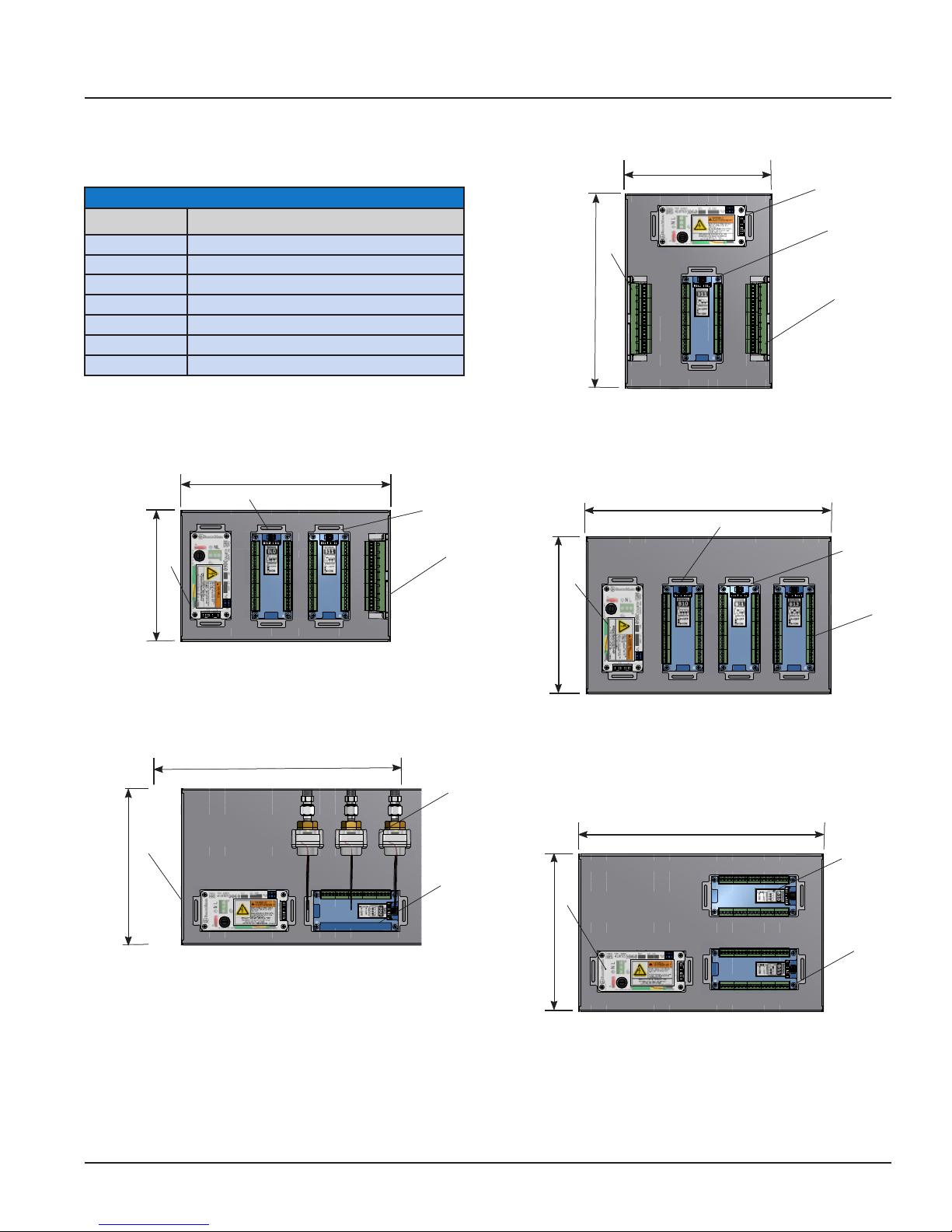
MEGA3 NFPA Medical Gas Notification System
Layout-2
Layout-3
1
2
3
4
5
6
7
Layout-3
1
2
3
4
5
1
2
3
Layout-2
Layout-3
Layout-5A
1
2
3
4
5
Layout-3
1
2
Typical Retrofit Layouts
(Recommended Installation)
Module Components
Letter Designator Description
A B05 Power Supply
B B10-B12 Module (Signals, 20 Inputs)
C B20 Module (TotalAlert2 Retrofit only, 64 Inputs)
D B40-B43 Module (16 Relay Out)
E B50 Module (4-20mA, 4 devices, 7 inputs, 6 outputs)
F B60 Module (Gas Input, 8 gases, 1 output)
G B65 Module (Combination, 3 gases, 10 inputs, 6 outputs)
Dimensions
12.00in
(30.5cm)
B
7.50in
A
(19.1cm)
Digital I and II Alarm from Chemetron
Layout-2
8.38in
(21.3cm)
A
B
B
11.13in
(28.3cm)
Multi-Signal Alarm from Medaes, Ohmeda, or Ohio
Layout-1
B
14.00in
(35.6cm)
B
B
B
B
A
9.00in
B
(22.9cm)
9.00in
(22.9cm)
14.00in
(35.6cm)
A
Layout-5
MedPlus Medical Gas Alarm from Hill-Rom
or Medaes or Alert1 and 2 Series Alarm from
Amico
GAS SENSOR
F
(22.9cm)
9.00in
MedPlus Medical Gas Alarm from Hill-Rom
or Medaes or Alert1 and 2 Series Alarm from
Amico
Layout-3
14.00in
(35.6cm)
A
MedPlus Medical Gas Alarm from Hill-Rom
or Medaes or Alert1 and 2 Series Alarm from
Amico
Layout-5A
B
B
5-13
4107 9016 59.03
Page 72

MEGA3 NFPA Medical Gas Notification System
7.50in
(19.1cm)
8.38in
(21.3cm)
12.00in
(30.5cm)
GAS SENSOR
8.38in
(21.3cm)
A
A
F
11.13in
F
(28.3cm)
Digital I and II Alarm from Chemetron
8.38in
(21.3cm)
A
F
Line Pressure Alarms from Medaes,
Ohmeda, or Ohio
8.38in
GAS SENSOR
(21.3cm)
A
15.00in
(38.1cm)
Line Pressure Alarms from Medaes,
Ohmeda, or Ohio
12.00in
(30.5cm)
TA1 Master Retrofit
F
B
GAS SENSOR
A
B
F
14.44in
(36.7cm)
GAS SENSOR
Line Pressure Alarms from BeaconMedaes, Medaes,
Ohmeda, or Ohio
4107 9016 59.03
5-14
Page 73

MEGA3 NFPA Medical Gas Notification System
18.00in
(45.7cm)
7.50in
(19.1cm)
GAS SENSOR
7.50in
(19.1cm)
A
Digital I and II Alarm from Chemetron
F
21.00in
(53.4cm)
GAS SENSOR
A
Line Pressure Alarms from Medaes, Ohmeda, or Ohio
F
24.00in
(61.0cm)
9.00in
(22.3cm)
A
MedPlus Medical Gas Alarm from Hill-Rom or
Medaes or Alert 1 and 2 Series Alarm from Amico
5-15
GAS SENSOR
F
4107 9016 59.03
Page 74

Page 75

MEGA3 NFPA Medical Gas Notification System
6.0 Maintenance
Power/Sensor
Hole Plug
Part # 836836-00
Alarm Panel Box
(Part# 4107 6538 30)
Gas Sensor
Module**
See Table 1
Front Panel Assembly
(Part# 4107 2129 01)
Power Supply
(Part# 4107 2130 05)
I/O Board*
See Table 2 for complete list
Figure 138: Maintenance
6-1
4107 9016 59.03
Page 76
MEGA3 NFPA Medical Gas Notification System
*Table 1: Gas Sensor Module Options
(Service replacement only)
Part Number Gas Sensor Assembly
4107 4016 54 O2 Sensor Assembly
4107 4016 55 N2O Sensor Assembly
4107 4016 56 MedAir Sensor Assembly
4107 4016 57 Vac Sensor Assembly
4107 4016 58 N2 Sensor Assembly
4107 4016 59 IAIR Sensor Assembly
4107 4016 60 WAGD Sensor Assembly
4107 4016 61 CO2 Sensor Assembly
4107 4016 62 CO2-O2 Sensor Assembly
4107 4016 63 O2-CO2 Sensor Assembly
4107 4016 64 HE-O2 Sensor Assembly
4107 4016 65 O2-HE Sensor Assembly
4107 4016 66 HE Sensor Assembly
4107 4016 67 LAB-AIR Sensor Assembly
4107 4016 68 LAB-VAC Sensor Assembly
4107 4016 69 O2-100 Sensor Assembly
4107 4016 70 MedAir-100 Sensor Assembly
4107 4016 71 CO2-100 Sensor Assembly
4107 4016 72 AR Sensor Assembly
4107 4016 73 AGSS Sensor Assembly
4107 4016 74 O2-N2O Sensor Assembly
**Table 2: I/O Boards
Part Number I/O Boards Description
4107 4016 37 B05 Power Module Power supply
4107 4016 38 B1X (Signal Input
Board)
4107 4016 41 B4X (Relay Board) 16 Relay
4107 4016 42 B50 (4-20mA Com-
bination Board)
4107 4016 43 B60 (Gas Input
Board)
4107 4016 44 B65
(Gas Combination
Board)
20 Inputs
Outputs
4 Inputs
for 4-20mA
Signals
8 Gases
3 Gases, 7 Inputs, 6 Relay
Outputs
Cleaning:
Use clean dry microfiber cloth or soft lintfree cloth to remove any smudges located on
the touchscreen. Make sure not to apply too
much pressure on the screen when cleaning
it. Never use paper towels or tissue paper
which contain wood fibers that will scratch
any plastic surface.
4107 9016 59.03
Periodic Maintenance:
Inspect the alarm periodically and perform
a self test (see Section 4.1.6 - Information
Screen). This ensures proper operation of the
alarm. Any damaged components inside the
alarm should be replaced by a authorized
BeaconMedæs service technician.
6-2
Page 77
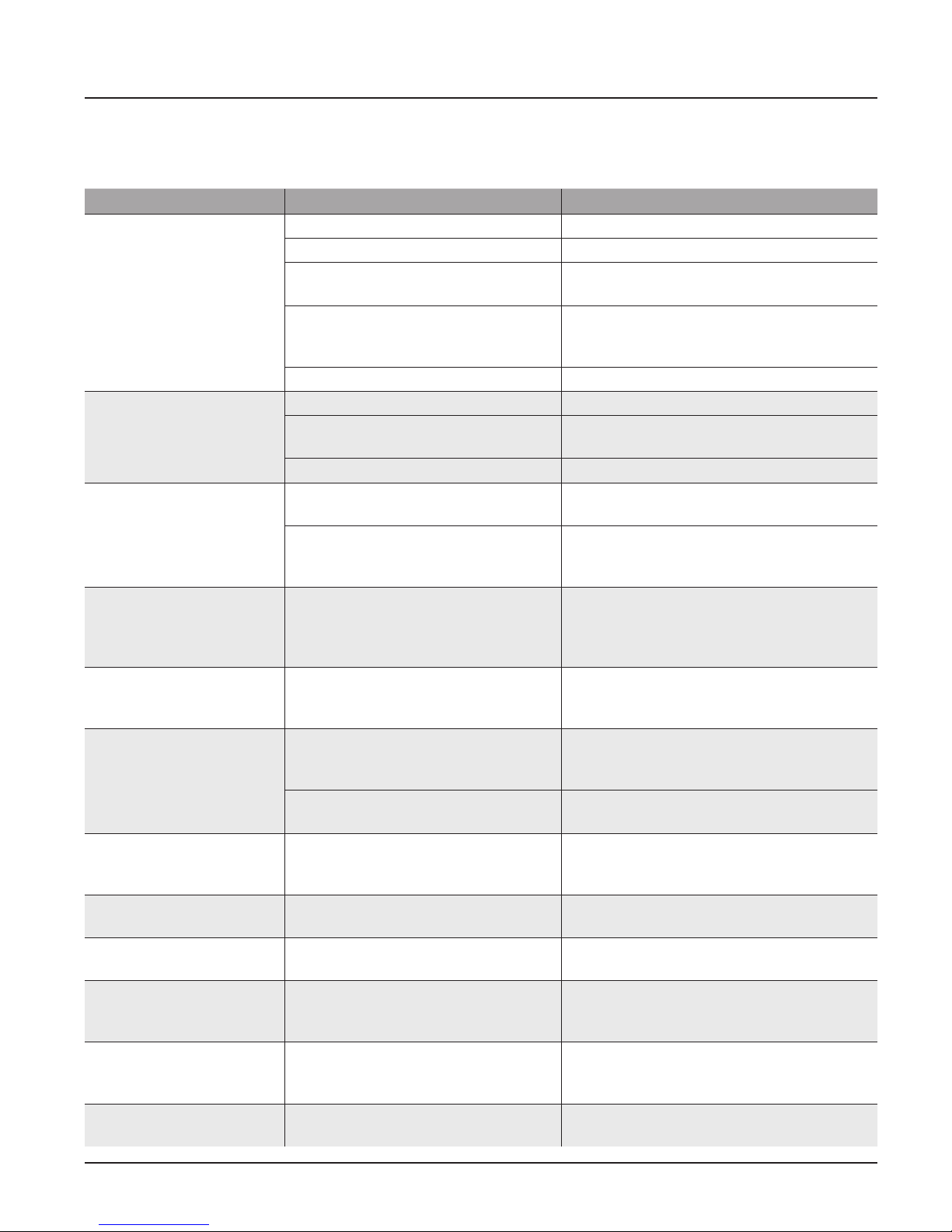
MEGA3 NFPA Medical Gas Notification System
7.0 Troubleshooting
Symptom Possible Cause Corrective Action
No LED power indicator
illuminated on alarm
front panel
No green “heartbeat”
power indicator is illuminated on connected
boards
No green “heartbeat”
power indicator is illuminated on gas sensor
Fast green "heartbeat"
power indicator is illuminated on gas sensor (2
beats per second)
Red LED illuminated
above warning indicator
( ! ).
Lost Connection
Warning
Input active and
Unassigned Warning
Sensor active and
Unassigned Warning
F1 displayed on Area
badge
F2 displayed on Area
badge
F3 displayed on Area
Badge
F4 displayed on Area
Badge
AC power is not turned on Check AC power source.
Blown power supply fuse Replace fuse.
AC power wiring is not connected Check AC entrance wiring at power supply
terminals.
Power supply DC wire harness is not
connected properly between the
power supply and the main board
Faulty power supply assembly Replace power supply
Board has not been initialized Initialize board per instructions in manual.
Board dip switches are not set cor-
rectly.
Cable not connected correctly Check cable connections between boards.
Sensor not connected to the Gas
Input Board.
Gas Input Board does not have power
(no “heartbeat”)
Sensor is reading out of range Verify gas pressure in pipeline. If normal,
Active warning Navigate to the warning screen by press-
Alarm has lost network communication with manually enrolled device
The alarm has lost connection to a
connected/ initialized board.
Master signal input is wired, but not
assigned/programmed to an alarm
signal
Sensor is wired to the sensor input
board, but not assigned/programmed
Gas sensor is not connected or has
shorted.
Gas sensor is reading below range
(fault low).
Gas sensor is reading above range
(fault high).
Gas sensor connected is wrong type
of gas.
Check connections on each end including
orientation of cable connectors. Reconnect
if necessary.
Set dip switches per diagram on board
label.
Verify correct sensor connection to Gas
Input Board.
Verify that Gas Input Board has been initialized and that dip switches are set correctly.
See item 2 above.
replace sensor.
ing the Information button, then selecting
Warnings.
Correct communication problem with
networked device or remove the enrolled
device from the Enrolled Devices list.
Check connections and cable to board.
Assign the wired input to a valid alarm
signal.
Assign the wired gas sensor to a valid gas
input.
Check gas sensor connection. If connection
is good, replace sensor.
Verify gas sensor connections and pipeline
pressure. If connection and pressure are
good, replace sensor.
Verify gas sensor connections and pipeline
pressure. If connection and pressure are
good, replace sensor.
Connect the correct type gas sensor.
7-1
4107 9016 59.03
Page 78
MEGA3 NFPA Medical Gas Notification System
Troubleshooting (continued)
Symptom Possible Cause Corrective Action
Area Display pressure/
vacuum reading not
matching pipeline.
High or Low alarm, with
normal pressure displaying on Area display
Screen is blank, power on
LED is illuminated
Audible alarm reactivates
a short period of time
after Silence button has
been pressed
Bad gauge on pipeline Verify gauge used on pipeline
Incorrect unit of measure Check unit of measure, if incorrect, repro-
gram unit of measure.
Gas sensor out of calibration Adjust Zero Oset to correct reading.
(Note: there is a max of 3 psi / 3 “hg oset
adjustment). If sensor cannot be adjusted
enough, replace sensor.
Alarm set points have been changed. Verify / correct alarm set points.
Screen backlight will time out and
shut o. Motion sensor will awaken
screen when motion is sensed within
5 ft of screen.
A new alarm condition has occurred. If alarm condition previously silenced,
If screen does not awaken when approaching alarm, touch screen to awaken. Possible
bad motion sensor.
self corrects and then reactivates again,
the alarm panel treats this as a new alarm
condition.
4107 9016 59.03
7-2
Page 79

Blank Page
Page 80

1800 Overview Drive Rock Hill, SC 29730
Andersen Medical Gas
12 Place Lafifitte
Madisonville, LA 70447
http://www.TheMedicalGas.com
1-866-288-3783
(888) 4-MEDGAS (888) 463-3427
Fax (803) 817-5750
www.beaconmedaes.com
 Loading...