

Page 1
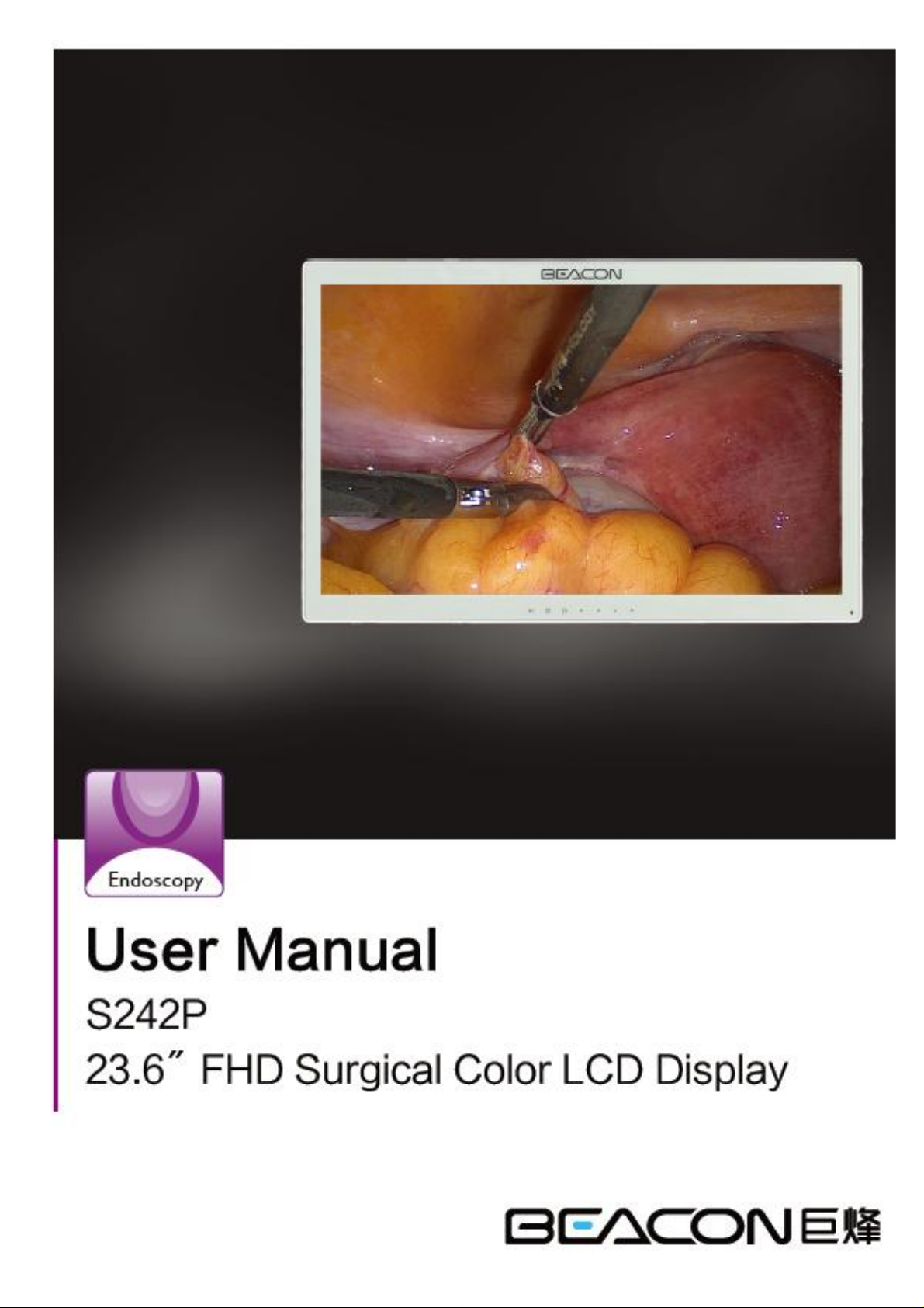
S242P User Manual
1
Page 2

S242P User Manual
TABLE OF CONTENTS
1. SAFETY SYMBOLS & PRECAUTIONS ................................................................................................ 3
1.1 SAFETY SYMBOLS ............................................................................................................... 3
1.2 PRECAUTIONS ...................................................................................................................... 3
2. INTRODUCTION ..................................................................................................................................... 7
2.1 CONTROL AND CONNECTOR ............................................................................................ 7
3. QUICKLY STARTING .............................................................................................................................. 8
3.1 CONNECTING THE CABLES .............................................................................................. 8
3.2 STARTING UP........................................................................................................................ 8
4. OSD MENU .............................................................................................................................................. 9
4.1 OSD MENU INTRODUCTION...................................................................................................... 10
5. TROUBLESHOOTING .......................................................................................................................... 11
6. CLEANING ............................................................................................................................................. 12
7. PRODUCT PACKAGING AND ACCESSORIES ................................................................................. 13
8. SPECIFICATION .................................................................................................................................... 14
8.1 SPECIFICATION ............................................................................................................................ 14
8.2 D-SUB 15 PIN CONNECTOR ........................................................................................................ 15
8.3 DVI-D CONNECTOR ..................................................................................................................... 15
8.4 CVBS CONNECTOR ..................................................................................................................... 15
8.5 S-Video CONNECTOR ................................................................................................................... 15
8.6 YPbPr/RGB CONNECTOR ............................................................................................................ 16
8.7 PRESET TIMING ........................................................................................................................... 16
9. DECLARATION OF CONFORMITY .................................................................................................... 17
2
Page 3
S242P User Manual
l SAFETY SYMBOLS & PRECAUTIONS
l SAFETY SYMBOLS
Medical displays are mainly used to provide trained medical staff with professional digital images, thus for
the professional reading and analysis.
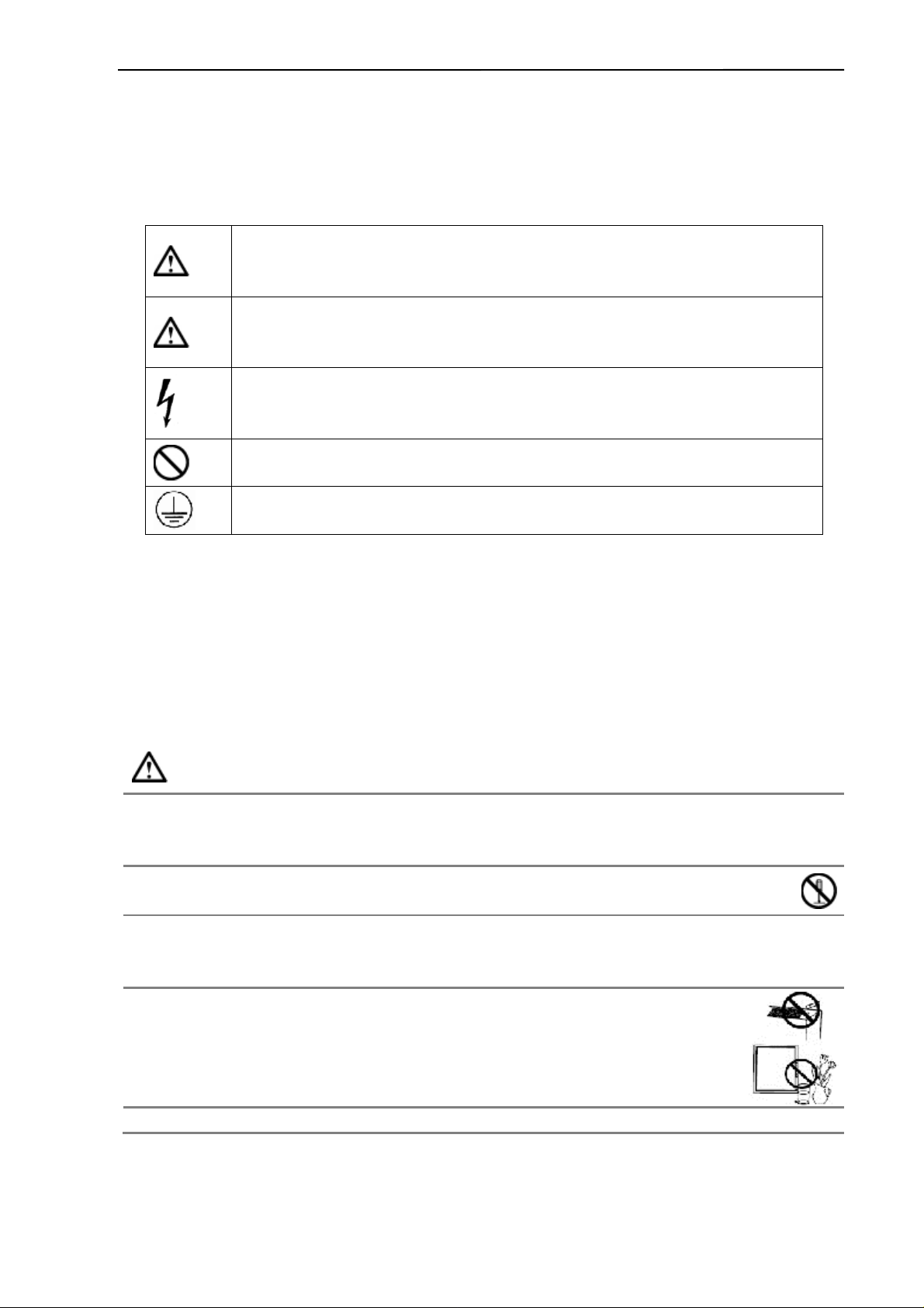
This manual uses the safety symbols below. They denote critical information. Please read them carefully.
WARNING
Failure to abide by the information in a WARNING may result in serious injury and can be
life threatening.
CAUTION
Failure to abide by the information in a CAUTION may result in moderate injury and/or
property or product damage.
Alert electrical hazard.
To prevent fire or shock hazard, do not expose the device in rain or in wet environments. This monitor is
completely safe for the patients. This device is not recommended to connect household equipments.
Although every effort to ensure the latest information provided in this manual. please note that monitor
specifications are subject to change without notice.
Indicates a prohibited action.
Indicates to ground for safety.
l PRECAUTIONS
To ensure personal safety and proper maintenance, please read this section and the caution statements on
the unit.
WARNING
If the unit begins to emit smoke, smells like something is burning, or makes strange noises, disconnect all
power connections immediately and contact your dealer for advice.
Attempting to use a malfunctioning unit may result in fire, electric shock, or equipment damage.
Do not open the cabinet or modify the unit.
Opening the cabinet or modifying the unit may result in fire, electric shock, or burn.
Refer all servicing to qualified service personnel.
Do not attempt to service this product yourself as opening or removing covers may result in fire, electric shock,
or equipment damage.
small objects or liquids away from the unit.
Small objects accidentally falling through the ventilation slots into the cabinet or spillage into
the cabinet may result in fire, electric shock, or equipment damage. If an object or liquid
falls/spills into the cabinet, unplug the unit immediately. Have the unit checked by a qualified
service engineer before using it again.
This monitor can be a long boot, but the life will be reduced.
3
Page 4

S242P User Manual
Place the device on a solid and stable surface.
If the unit is placed on an inadequate surface may occur fall and result in personal injury or
equipment damage. If the unit falls, disconnect the power immediately and ask dealer for
help. Please do not continue to use damaged equipment. Using a damaged unit may result in
fire or electric shock.
Set the unit in an appropriate location.
Not doing so may result in fire, electric shock, or equipment damage.
l Do not place outdoors.
l Do not place in the transportation system (ship, aircraft, trains, automobiles,
etc.
l Do not place in a dusty or humid environment.
l Do not place in a location where the steam comes directly on the screen.
l Do not place near heat generating devices or a humidifier.
l Do not place in an inflammable gas environment.
To avoid danger of suffocation, keep the plastic packing bags away from babies and children.。
Use the enclosed power cord and connect to the standard power outlet of your country.
Be sure to remain within the rated voltage of the power cord. Not doing so may result in fire or electric shock.
To disconnect the power cord, grasp the plug firmly and pull.
Tugging on the cord may damage and result in fire or electric shock.
The equipment must be connected to a grounded main outlet.
Not doing so may result in fire or electric shock.
Use the correct voltage.
l The unit is designed for use with a specific voltage only. Connection to another voltage than specified
in this User’s Manual may cause fire, electric shock, or equipment damage.
l Do not overload your power circuit, as this may result in fire or electric shock.
Handle the power cord with care.
l The unit is designed for use with a specific voltage only. Connection to another
voltage than specified in this User’s Manual may cause fire, electric shock, or
equipment damage.
l Do not overload your power circuit, as this may result in fire or electric shock.
Never touch the plug and power cord if it begins to thunder.
Touching them may result in electric shock.
Do not touch a damaged LCD panel directly with bare hands.
The liquid crystal that may leak from the panel is poisonous if it enters the eyes or mouth. If any part of the
skin or body comes in direct contact with the panel, please wash thoroughly. If some physical symptoms result,
please consult your doctor.
Follow local regulation or laws for safe disposal.
CAUTION
4
Page 5
S242P User Manual
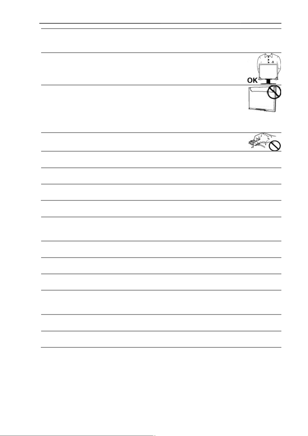
Handle with care when carrying the unit.
Disconnect the power cord and signal cables and remove the optional unit. Moving the unit with the cord or the
option attached is dangerous. It may result in injury.
When handling the unit, grip the bottom of the unit firmly with both hands ensuring the
panel faces outward before lifting.
Dropping the unit may result in injury or equipment damage.
Do not block the ventilation slots on the cabinet.
l Do not place any objects on the ventilation slots.
l Do not install the unit in a closed space.
l Do not use the unit laid down or upside down.
Blocking the ventilation slots prevents proper airflow and may result in fire, electric shock, or equipment
damage.
Do not touch the plug with wet hands.
Doing so may result in electric shock.
Periodically clean the area around the plug.
Dust, water, or oil on the plug may result in fire.
Unplug the unit before cleaning it.
Cleaning the unit while it is plugged into a power outlet may result in electric shock.
If you plan to leave the unit unused for an extended period, disconnect the power cord from the wall
socket after turning off the power switch for the safety and the power conservation.
LCD PANEL
When the monitor is cold and brought into a room or the room temperature goes up quickly, dew condensation
may occur inside and outside the monitor. In that case, do not turn the monitor on and wait until dew
condensation disappears, otherwise it may cause some damages to it.
In order to suppress the luminosity change by long-term use and to maintain the stable luminosity, please use the
monitor with the lower brightness.
The screen may have defective pixels. These pixels may appear as slightly light or dark area on the screen. This
is due to the characteristics of the panel itself, and not the product.
The backlight of the LCD panel has a fixed life span. When the screen becomes dark or begins to flicker, please
contact your dealer.
Do not press on the panel or edge of the frame strongly, as this may result in damage to the screen. There will be
prints left on the screen if the pressed image is dark or black. If pressure is repeatedly applied to the screen, it
may deteriorate or damage your LCD panel. Leave the screen white to decrease the prints.
Do not scratch or press on the panel with any sharp objects, such as a pencil or pen as this may result in damage
to the panel. Do not attempt to brush with tissues as this may scratch the LCD panel.
When the screen image is changed after displaying the same image for extended periods of time, an afterimage
may appear. Use the screen saver or timer to avoid displaying the same image for extended periods of time.
5
Page 6
S242P User Manual
FCC Warning:
This device complies with Part 15 of the FCC Rules. Operation is subject to the following two
conditions: (1) this device may not cause harmful interference, and (2) this device must accept any
interference received, including interference that may cause undesired operation.
Changes or modifications not expressly approved by the party responsible for compliance
could void the user's authority to operate the equipment.
NOTE: This equipment has been tested and found to comply with the limits for a
Class B digital device, pursuant to Part 15 of the FCC Rules. These limits are
designed to provide reasonable protection against harmful interference in a
residential installation. This equipment generates, uses and can radiate radio
frequency energy and, if not installed and used in accordance with the
instructions, may cause harmful interference to radio communications. However,
there is no guarantee that interference will not occur in a particular installation.
If this equipment does cause harmful interference to radio or television reception,
which can be determined by turning the equipment off and on, the user is
encouraged to try to correct the interference by one or more of the following
measures:
-- Reorient or relocate the receiving antenna.
-- Increase the separation between the equipment and receiver.
-- Connect the equipment into an outlet on a circuit different
from that to which the receiver is connected.
-- Consult the dealer or an experienced radio/TV technician for help.
6
Page 7

S242P User Manual
l INTRODUCTION
S242P is a professional full HD surgery medical image display used in the operating room with the
characteristic such as high definition and high brightness.
This product is with precise calibration and completely compliant with standard of medical imaging, it uses the
latest generation of LED backlight panel, supports resolution 1920 x1080, provides HD display for the output of
surgery, endoscope and etc. With built-in brightness stabilization control circuit and 12 bit image processing
technology, make sure the product meet the demand of high precision medical imaging. With a variety of
interfaces, it is suitable for a variety of digital operating equipment signals. The products comply with
IEC60601-1, IEC 60601-1-2 safety and EMC standards and CCC safety certification
l CONTROL AND CONNECTOR
a. The front side of the monitor
b. The back side of the monitor
7
Page 8

l QUICKLY STARTING
Note: Be sure that the power switches of both the computer and the monitor are OFF.
l CONNECTING THE CABLES
Put the signal cable into the back of the monitor connector, then plug the other end into the
computer's display interface. As shown in the figure below.
After connecting, tighten the screws.
l STARTING UP
Put the power cord into the back of the monitor power connector, then plug the other end into a power
outlet. Turn on the switch of the monitor, meanwhile, the power indicate LED will be light (blue
color).Then start the computer or the device.
Set the display mode as bellow: Resolution: 1920x1080, Refresh ratio: 60Hz.
If no image shown in the screen, please refer to the "failure analysis" to get help.
S242P User Manual
WARNING
Please use the enclosed power cord to connect the standard power outlet.
Please ensure that the monitor's power plug can be fully inserted into the socket. Make sure the power cord used
within the rated voltage. Or it may result in fire or electric shock.
Equipment must be connected to a outlet that grounded good.
Or it may result in fire or electric shock.
Please turn on the monitor and then computer power.
The monitor's power indicator will light (green). If the image does not appear, refer to the "failure analysis" for
help. After each use, turn off the computer and the monitor.
Note:
This monitor can run for a long time, but life will be reduced. Recommended 10-minute break every hour.
8
Page 9

l OSD MENU
l SIGNAL INDICATOR
Color Display mode
Blue Operating mode
Orange Standby mode
None Power off mode
l SHORTCUTS
S242P User Manual
Key Function
Left
Right
Up
Down
l KEY FUNCTION
Reduce brightness values
Increase brightness values
Reduce contrast values
Increase contrast values
Keys Function
Signal switching Signal switching
Menu/Confirm
EXIT Exit menu/Automatic adjust displays
Left Move to the left column
Right Move to the right column
Enable the menu and moved to the next entry
column/confirm the choice
Up Move to the last column or reduce values
Down Move to the next column or increase values
9
Page 10

4.1 OSD MENU INTRODUCTION
Main Menu Sub Menu Reference
Main Input VGA/DVI /CVBS /S-VIDEO/YPbPr/ RGB/SDI
Input
PIP Mode Large pip, Side-by-side, Off
Brightness Brightness adjust
S242P User Manual
Image
Setup
Contrast
Sharpness
Aspect Ratio
Mode Select
Color Temp 5500K/6500K/7500K/8500K/9300K/10000K/User
Gamma DICOM/ 2.4/2.3/2.2/ 2.1/ 2.0/ 1.8
RGB/ YPbPr
RGB/ YPbPr SEL
OSD Position
OSD Language English /Chinese
Auto Scan Input On off
Factory Reset Restore the factory default parameters
Auto Adjust
Contrast adjust
Sharpness adjust
5:4/ 4:3/ Full/ Full Aspect/ Native/ User
Overlapping mode selection(According to different input
signal to select different suitable overlapping mode.
RGB/YPbPr signal select
Center/Top Left/Top Right
Bottom Left/Bottom Right
H-position
VGA
Lock Key Lock Lock or unlock the touch-key shortcut functions
Status
V-position
Clock
Phase
FW version Software version information
Main Input The input information of main signal source
Main Format The input signal format of main singnal source
Automatic adjust displays,Detailed to see 5.2-5.4.
10
Page 11

S242P User Manual
l TROUBLESHOOTING
If a problem persists even after applying the suggested remedies, contact a dealer.
Problems Points to check with Possible Solutions
1. No picture
Indicator status: Off
Indicator status: Green Check the <Backlight> shortcut key setting.
Indicator status: Orange Try pressing the keys on the computer keyboard or clicking the mouse。
2.Display position is incorrect.
3.Vertical bars of distortion
appear.
4.Horizontal bars of distortion
appear.
Check that the power cord is correctly connected. If the problem persists,
turn off the monitor power for a few minutes, then turn it back on and try
again.
Adjust the image position by using the <H-Position> and <V-Position>.
If the problem persists, use the graphics board's utility software to change
the display position if available.
Decrease the horizontal bars by using the <Clock>.
Decrease the horizontal bars by using the <Phase>.
5.The screen is too bright or too
dark.
6.After image phenomena
appear
7.The screen has defective pixels
8.Shiatsu traces left on the
screen
Adjust <Backlight>shortcut key (The backlight of the LCD monitor has a
fixed life span. When the screen becomes dark or begins to flicker, please
contact your dealer.)
l Make sure that whether you have used the screen saver or timer
when displaying the same image for extended periods of time
or not.
l Afterimages are particular to LCD monitors. Avoid displaying
the same image for extended periods of time.
This is due to the characteristics of the panel itself, and not the LCD
product.
Keep the screen background white can solve this problem.
11
Page 12

S242P User Manual
l CLEANING
Periodic cleaning is recommended to keep the outlook of monitor clean and prolong the life time.
Note: Never use thinner, benzene, alcohol (ethanol, methanol or isopropyl alcohol), abrasive cleaners or other
solvents before the solubility, as they may damage the cabinet or LCD screen.
Cabinet
To remove stains, use a soft cloth lightly moistened with a mild detergent solution.
Do not spray wax or cleaner directly into the cabinet. (For details, refer to the manual of the PC.)
LCD Panel
The LCD surface can be cleaned with a soft cloth, such as cotton or lens paper.
If necessary, use part of damp cloth ( to improve its cleaning ability ) to remove Stubborn stains.
12
Page 13

l PRODUCT PACKAGING AND ACCESSORIES
LCD monitor
Power cable
DVI signal cable
BNC signal cable
S-VIDEO signal cable
User manual
Power adapter
S242P User Manual
13
Page 14

l SPECIFICATION
8.1 SPECIFICATION
LCD panel 23.6”, TFT color LCD, AG, Hard coating
Brightness(Typ.) 400 cd/m2
Contrast 1000:1
response speed 15ms
Viewing angle Horizontal&Vertical:178°atΦ=0°,90°,180°,270° CR >10
Pixel pitch 0.2715 mm x 0.2715 mm
Horizontal
scanning frequency
Vertical
scanning frequency
Resolution 1920 x 1080
Support color 1.07 Billion
Power supply DC:24V(4.2A)
Power consumption Max:45 W
Input interface VGA 15 pin D-sub,0.7 Vp-p,separate sync
31~80 kHz
50~76 Hz
DVI 24pin, DVI-D,TDMS signal
SDI BNC,75Ohm terminated
CVBS
BNC, 75Ohm terminated ( Support : PAL/
NTSC/SECAM)
S242P User Manual
S-VIDEO DIN-4, 1VppY-signal, +/-300mV C-signal
YPbPr/RG
B
Output interface CVBS, YPbPr, S-VIDEO, DVI, SDI
Service interface RS232 D-SUB 9PIN
Plug and Play VESA DDC 2B
Weight 6.0kg
Temperature Operating:0°C ~ 40°C
Store:-20°C ~ 60°C
Humidity 30%~80% R.H. non-condensing
BNC, 1Vpp Y signal, +/-350mV Pb,Pr signal
14
Page 15

S242P User Manual
8.2 D-SUB 15 PIN CONNECTOR
Pin Signal Pin Signal Pin Signal
1 Red video 6 Red ground 11 Ground Shorted
2 Green video 7 Green ground 12 Data (SDA)
3 Blue video 8 Blue ground 13 H. Sync
4 Ground 9 5V 14 V. Sync
5 GND 10 Ground Shorted 15 Clock (SCL)
8.3 DVI-D CONNECTOR
Pin Signal Pin Signal Pin Signal
1 TMDS Data 2- 9 TMDS Data 1- 17 TMDS Data 02 TMDS Data 2+ 10 TMDS Data 1+ 18 TMDS Data 0+
3 TMDS Data 2/4 Shield 11 TMDS Data 1/3 Shield 19 TMDS Data 0/5 Shield
4 TMDS Data 4- 12 TMDS Data 3- 20 TMDS Data 55 TMDS Data 4+ 13 TMDS Data 3+ 21 TMDS Data 5+
6 DDC Clock (SCL) 14 +5V Power 22 TMDS Clock shield
7 DDC Data (SDA) 15 Ground (For +5V) 23 TMDS Clock+
8 NC 16 Hot Plug Detect 24 TMDS Clock-
(*NC:No connection)
8.4 CVBS CONNECTOR
Pin signal
1 CVBS
2 GND
8.5 S-Video CONNECTOR
Pin signal
1 GND
2 GND
3 Y
4 C
15
Page 16

S242P User Manual
8.6 YPbPr/RGB CONNECTOR
Y/G Pb/B Pr/R
Pin Signal
1 Y/G Pb/B Pr/R
2 GND GND GND
8.7 PRESET TIMING
l VGA/DVI preset timing
Formats Horizontal Frequency (kHz) Vertical Frequency (Hz) Pixel Clock (MHz)
720 x 400 31.5 70.1 28.3
640 x 480 31.5 59.9 25.2
800 x 600 37.9 60.3 40.0
1024 x 768 48.4 60.0 65.0
1280 x 1024 64.0 60.0 108.0
1600 x 1200 75.0 60.0 162.0
1920 x 1080 66.6 59.9 138.50
1920 x 1080 67.0 60.0 172.750
l RGB/YPbPr preset timing
Video Formats Horizontal Frequency (kHz) Vertical Frequency (Hz) Pixel Clock (MHz)
752 x 582i/50Hz 15.625 50.0 14.1875
480i/60Hz 15.734 59.940 13.5
576i/50Hz 15.625 50.0 13.5
480p/60Hz 31.469 59.940 27.0
576p/50Hz 31.25 50.0 27.0
720p/50Hz 37.50 50.0 74.250
720p/60Hz 45.00 60.0 74.250
1080i/50Hz 28.125 50.0 74.250
1080i/60Hz 33.750 60.0 74.250
1080p/50Hz 56.250 50.0 148.50
1080p/60Hz 67.500 60.0 148.50
l CVBS, S-VIDEO preset timing
Video Formats Horizontal Frequency(kHz) Vertical Frequency (Hz) Pixel Clock (MHz)
PAL(576i) 15.625 50.0 13.50
NTSC(480i) 15.734 59.940 13.50
16
Page 17

S242P User Manual
l SDI input preset timing
Video Formats Horizontal Frequency (kHz) Vertical Frequency (Hz) Pixel Clock (MHz)
480i/60Hz 15.734 59.940 13.50
576i/50Hz 15.625 50.0 13.50
720p/50Hz 37.50 50.0 74.250
720p/60Hz 45.00 60.0 74.250
1080i/50Hz 28.125 50.0 74.250
1080i/60Hz 33.750 60.0 74.250
l DECLARATION OF CONFORMITY
This equipment is in conformity with the provisions of the CCC, CE, IEC60601-1 standard.
This equipment satisfies the following two conditions:
l The device will not bring dangerous interference;
l The device will not be influenced by outer interference and cause unpredictable results.
l To avoid interference with radio or TV receiving, please use the power adapter and cable matched; Use
other cable and power adapter may interfere the other electronic equipment;
l This equipment has passed the standards of CCC; the device will have a wireless electromagnetic wave,
incorrect installation and using will cause interference with wireless communication systems.
l Please do the following steps if there is interference to the other devices when running this equipment:
l Adjust the angle and position of the radio or the television reception antenna;
l Increase the distance between this equipment and the radio or the television reception antenna;
l This equipment doesn’t share the same the power input circuit with the radio or the television reception
antenna;
l Please consult the professional person if any problem.
17
 Loading...