

Page 1
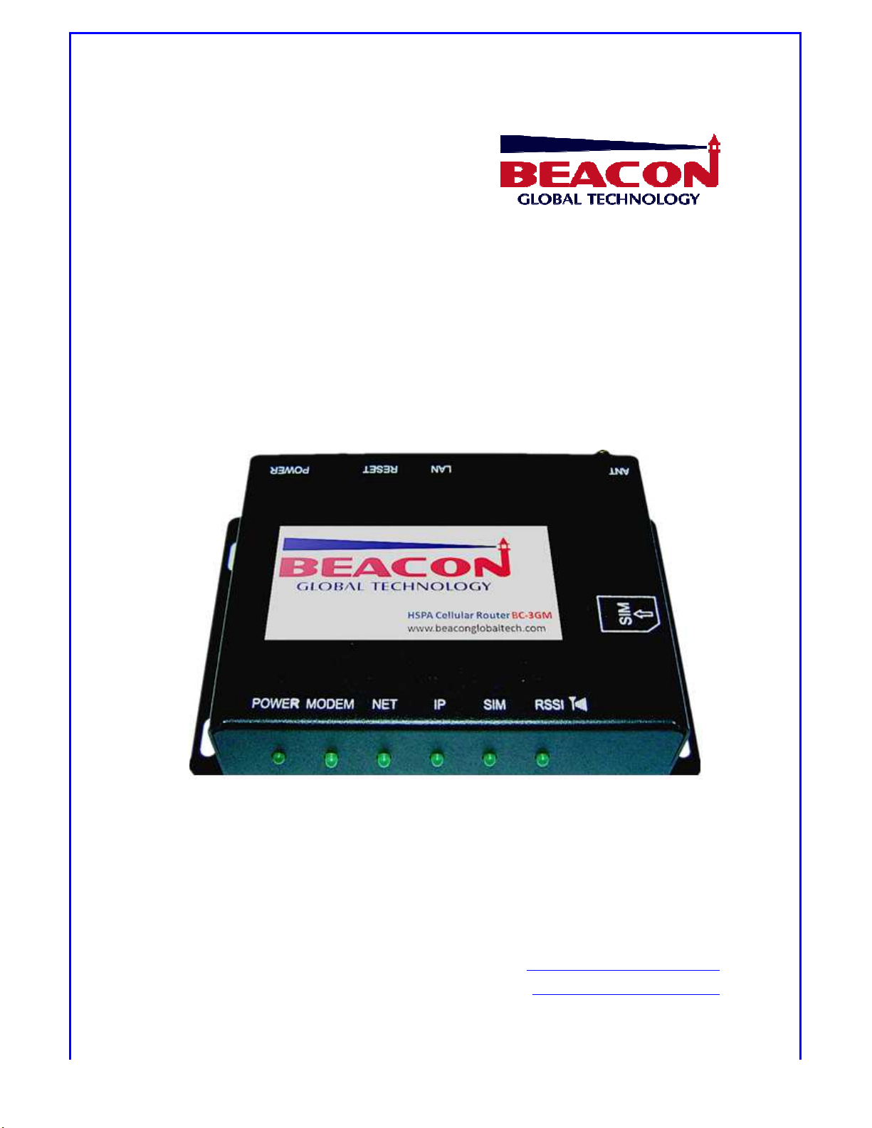
Cellular Router
Wireless
ith secure HTTPS
BEACON GLOBAL TECHNOLOGY
Page
anual
@beacon
lobal
BC-3GM User Manual
HSPA
3G
w
BC-3GM User M
Internet Access Device via HSPA
environment
1 of 39
VERSION: v1.1.49
Technical Support: tech.support
For more information: www.beacong
gt.com
tech.com
Page 2

BC-3GM User Manual Page 2 of 39
Table of Contents
Copyright ............................................................................................................................. 3
Purpose ................................................................................................................................ 3
Revision History ................................................................................................................ 3
Trademarks ......................................................................................................................... 3
Headquarter ....................................................................................................................... 3
1. INTRODUCTION ............................................................................................................ 4
1.1.
OVERVIEW ..................................................................................................... 4
1.2.
MAIN FEATURE ............................................................................................ 5
2.
BRIEF INFORMATION ....................................................................................... 6
2.1.
APPEARANCE ................................................................................................ 6
2.2.
COMPONENT ................................................................................................. 6
2.3.
PACKAGES ..................................................................................................... 8
2.4.
SOFTWARE COMPOSITION ...................................................................... 9
2.4.1. Web-based configuration page ....................................................... 9
2.4.2. Firmware ................................................................................................ 9
3.
BEFORE USAGE .................................................................................................... 9
3.1.
Installation ................................................................................................. 10
3.2.
Checking Device ........................................................................................ 10
3.3.
Understanding Modem Router Mode .................................................. 11
4.
SETTING UP YOUR PC ENVIRONMENT ...................................................... 12
4.1.
Setting up host PC .................................................................................... 12
5.
ACCESSING WSU (WEB-BASED SETTING UTILITY) .............................. 14
5.1.
How to access WSU .................................................................................. 14
5.2.
How to configure WSU ............................................................................ 15
6.
CONFIGURATION OF INTERNET CONNECTION ...................................... 15
6.1.
Setting up your cellular environment ................................................ 15
6.1.1. Accessing WSU ................................................................................... 15
7.
CONFIGURATION GUIDE ............................................................................... 29
7.1.
Rockwell/Allen-Bradley PLC Configuration ...................................... 29
7.1.1. Configuration Guide .......................................................................... 29
7.2.
MODBUS TCP SMS .................................................................................... 37
8.
INFORMATION OF SMS FUNCTION IN HSPA ROUTER .......................... 39
8.1.
DSR.REBOOT ............................................................................................... 39
8.2. DSR. NETINFO ............................................................................................... 39
8.3.
DSR.PPP = (ON or OFF) ........................................................................ 39
Page 3

BC-3GM User Manual Page 3 of 39
Copyright
This user manual describes features, especially usage of BC-3GM including
hardware and software. BEACON GLOBAL TECHNOLOGY has made best effort to
ensure that the information contained in this document is accurate and reliable.
This document is the property of BEACON GLOBAL TECHNOLOGY and implies no
license under patents, copyrights, trade secrets. No part of this publication should
be copied, reproduced, stored in a retrieval system, or transmitted, in any form or
by any means (electronic, mechanical, photographic, or otherwise) without the
prior permission of BEACON GLOBAL TECHNOLOGY.
Purpose
This manual includes how to use and configure the BC-3GM (Model name).
Revision History
This user manual is based on firmware version v1.1.49
Trademarks
All other products or technologies are the trademarks or registered trademarks of
their respective companies.
Headquarter
Beacon Global Technology Inc.
1812 Delacorte Dr.,Bakersfield,CA 93311
Page 4

BC-3GM User Manual Page 4 of 39
1. INTRODUCTION
1.1. OVERVIEW
BC-3GM is a 3G wireless internet access device with Ethernet interface, it
performs wireless internet service between PC and wireless WAN via HSPA
Cellular station.
BC-3GM integrates a HSPA modem, a 32-bit MCU, system memories, a
10/100 Ethernet, Embedded OS, various network protocols for wireless
internet.
BC-3GM has some additional functionalities which include Always On-line;
HTTP Log-On for security environment; IP Filtering and MAC filtering for
high security application.
BC-3GM also supports configuration change whenever/wherever
necessary through Internet.
BC-3GM supports Keep-Alive function to ensure 7*24 hours online service.
BC-3GM is the best choice for industrial application.
Page 5

BC-3GM User Manual Page 5 of 39
1.2. MAIN FEATURE
3G Wireless internet access device
Integrated 3G wireless HSPA modem
A 10/100Mbps Ethernet interface
Embedded Operating System
User friendly Web-based Management Tool
6-Status LED indicates real-time status of the device
An external power switch
Support various Network Protocols
Support sending both English and Chinese SMS messages through
EtherNet/IP services from Rockwell Automation devices
Support sending both English and Chinese SMS messages through
Modbus TCP command
DHCP Server
NAT(Network Address Translation)
Configuration change whenever/wherever necessary through Internet
HTTPS security access to avoid hackers attack
IP filtering, MAC filtering to ensure access for high security
Keep-Alive function to make sure system are 7*24 hours on-line.
Allow up to 3 registered cellular phones to send SMS messages to reboot
router and change settings.
Page 6
BC-3GM User Manual Page 6 of 39
2. BRIEF INFORMATION
2.1. APPEARANCE
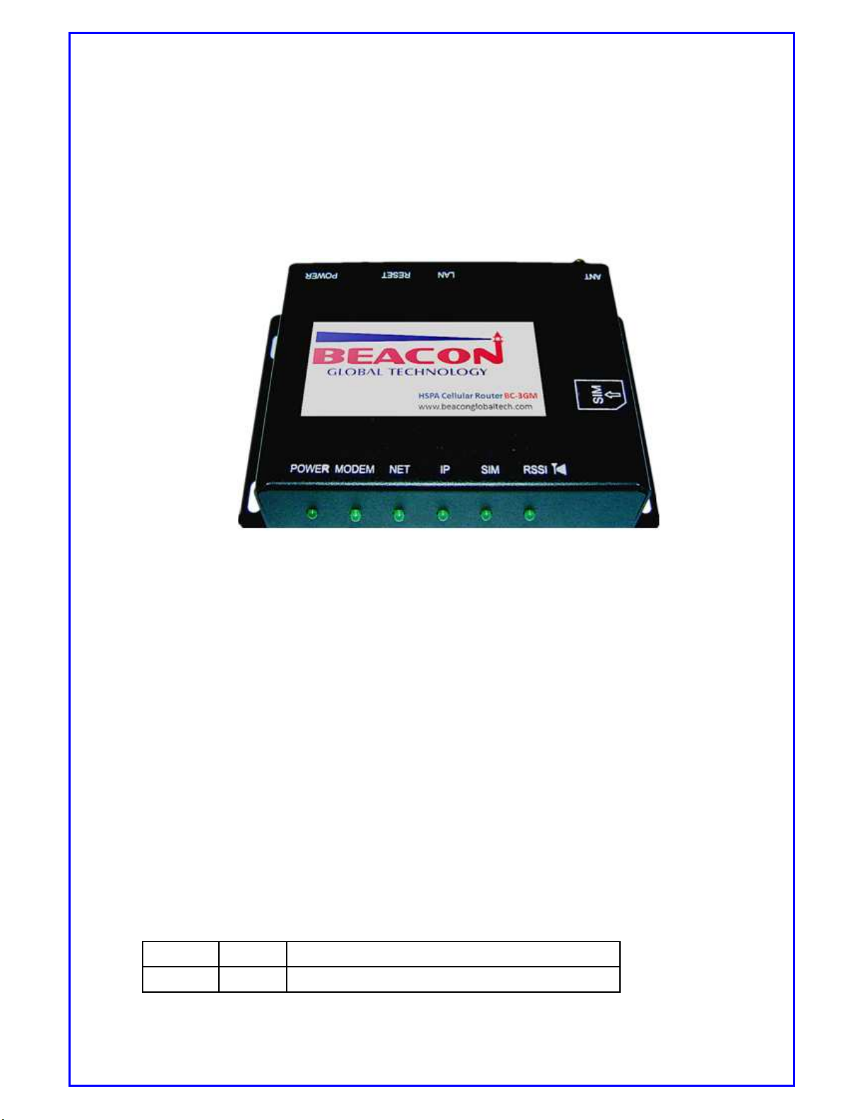
Below picture shows the appearance and structure of BC-3GM.
[Picture 2.1: BC-3GM Appearance ]
2.2. COMPONENT
2.2.1. MiniDCJack
Must connect the given power adapter DC 12V/1.5A on this jack.It can accept wide
range 6V-30VDC for industrial purpose.
2.2.2. Power S/W
Turn the power on or off.
2.2.3. Reset S/W
Reset the BC-3GM.
2.2.4. LAN
LED State Description
Green ON Indicates that 10Mbps LAN is connected.
Page 7
BC-3GM User Manual Page 7 of 39
Orange
BLINK Indicates that data exists via 10Mbps LAN.
OFF Indicates that 10M LAN is disconnected.
ON Indicates that 100Mbps LAN is connected.
BLINK Indicates that data exists via 100Mbps LAN.
OFF Indicates that 100M LAN is disconnected.
[Table 2.1 : LED indicator description on LAN port]
User can connect BC-3GM with Host PC, HUB, Router etc, via 10/100 LAN port. The
RJ-45 connector (LAN port) has two Link-LED. Table below lists out description for
each LED indicator.
2.2.5. Console
This port is for manufacturer use only. The console is designed mainly for diagnostic
data reading. Normally this port is for debugging.
2.2.6. Antenna Connector
This connector should be connected to an antenna.
2.2.7. HSPA Module
This Router supports 3G 800/850/900/1700/1900/2100MHz with upload 384Kbps,
downlink 21.1Mbps and uplink 7.2Mbps. 2G 850/900/1800/1900MHz
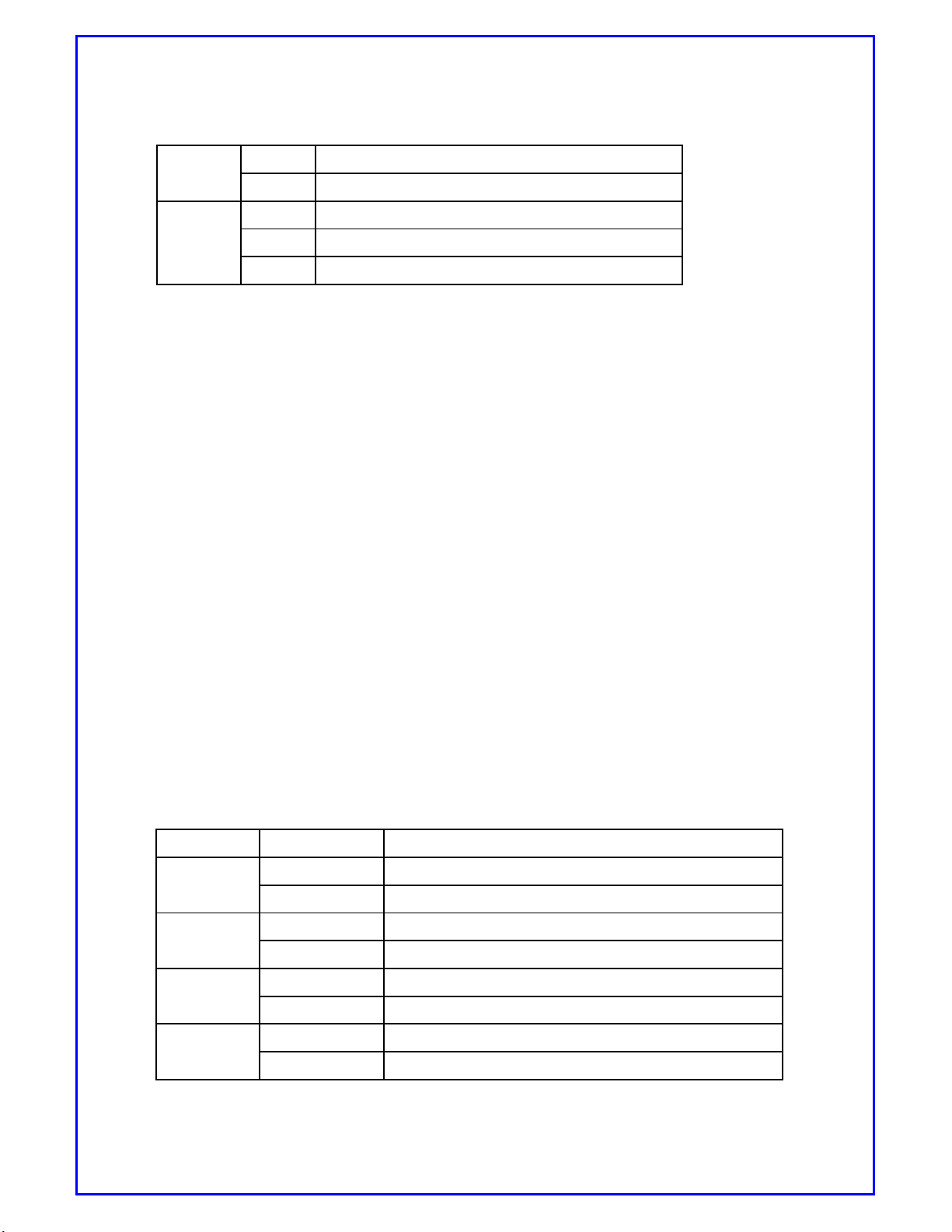
2.2.8. 6-Status LED
BC-3GM has 6-Status LED to indicate real-time status.
* The LED position are from left to right on top view
LED Display Description
Power
Modem
Net
IP
ON Indicates that main power is on
OFF Indicates that main power is off
ON Recognizes the HSPA modem
OFF Does not recognize the HSPA modem.
BLINK Indicates that data exists on 3G wireless network
OFF Indicates that data does not exist on 3G wireless network
ON Indicates that cellular IP is received from ISP
OFF Indicates that cellular IP is not achieved from ISP.
Page 8
BC-3GM User Manual Page 8 of 39
SIM
RSSI
[Table 2.2: 6-Status LED indication]
ON Indicates that U-SIM card is ready
OFF Indicates that U-SIM card is not ready
ON Indicates that RF signal sensitivity is perfect (Over 30)
RF signal sensitivity has low, fair, good, excellent
Excellent: RSSI >= -79dbm On Off with 0.25s
Good:-90dBM <= RSSI <= -80dBm Off 1.5s On 0.25s
Fair:-103dBM <= RSSI <= -91dBm Off 1s On 0.25s
Low and None:RSSI< -103dBm Off 0.5s On 0.25s
BLINK
OFF Indicates that RF signal sensitivity is poor.
This is based on CSQ level
None (99)
Low(from 0 to 4)
Fair(from 5 to 7)
Good(from 8 to 11)
Excellent(from 12 to 31)
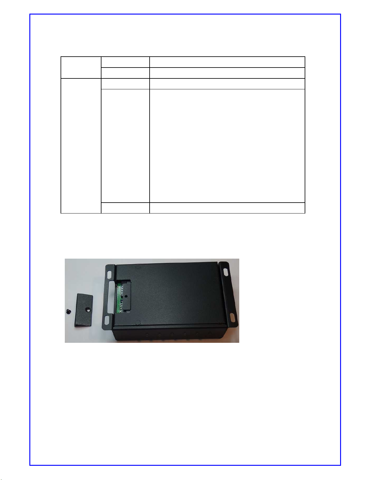
2.2.9. U-SIM Socket
For metal housing, it shows location of SIM card on the CASE.
[Picture 2.2: 6-Status LED indication]
2.3. PACKAGES
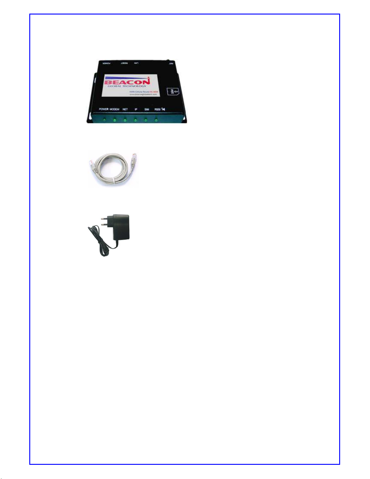
BC-3GM full package includes:
1. BC-3GM
Page 9
BC-3GM User Manual Page 9 of 39
2. UTP Cable (Direct)
3. DC 12V/1.5A Adapter
2.4. SOFTWARE COMPOSITION
BC-3GM software includes:
2.4.1. Web-based configuration page
BC-3GM has a web-based configuration page that user can access and
make changes on configurations.
2.4.2. Firmware
Firmware is the program operating the BC-3GM.
Firmware: Version BC-3GM- v1.1.49*
*
This version name will be changed whenever this is updated.
3.
PREPARE DEVICE
Page 10
BC-3GM User Manual Page 10 of 39
3.1. Installation
BC-3GM is a 3G wireless internet access device with PC or other LAN devices
via HSPA mobile station.
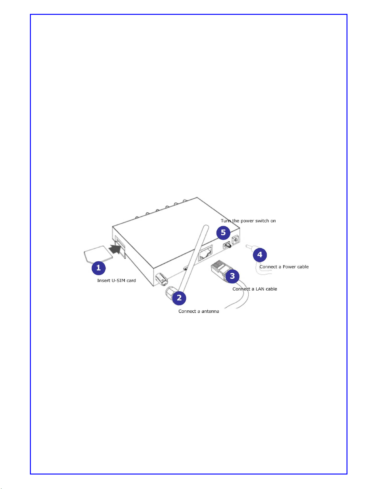
To install this device, please follow 5 steps below (corresponding position is
marked in picture 3) to complete installation.
1. Insert U-SIM card into the slot named “SIM”
2. Connect the proper antenna.
3. Connect the LAN cable between PC and LAN port of this device.
4. Connect the power adapter.
5. Turn on the power switch.
3.2. Checking Device
[Picture 3.1: Installation of BC-3GM]
Page 11

BC-3GM User Manual Page 11 of 39
BC-3GM initial status is set as PPP (NAT Router) and Always On-line mode.
When you get this device for the first time, it is suggested to perform device
check following below steps.
1. Install BC-3GM referring to “3.1 Installation.”
* Be sure the LAN cable must be connected between PC and BC-3GM.
2. When you turn on the power switch, the LED named “POWER” is on.
3. The LED named “MODEM” is on.
* You would see this LED on in 20 seconds. Should you met any problems please contact us
4. The LED named “SIM” is on.
* If this “SIM” LED is not on in 60 seconds, please check the whether the U-SIM card is
correctly inserted.
5. The LED named “NET” is asynchronously blinking.
* Whenever data are transferred or received from/to 3G wireless network, this “NET” LED will
be blinking asynchronously.
6. The LED named “RSSI” is on or blinking.
* When this “RSSI” LED is off, please check whether the antenna is correctly connected
7. The LED named “IP” is on.
* When you use wireless internet, this “IP” LED must be on. It might take a little while to get
cellular IP because it depends on the current mobile network status. If this LED is not on,
please check the configuration of [WAN] menu.
(Refer to “6.1.1 Accessing WSU, 3) Select [Network] page then Click [WAN] menu.” for
more details)
3.3. Understanding Modem Router Mode
On Modem router mode, BC-3GM gets an IP from ISP (Internet Service Provider)
then BC-3GM keeps the IP and shares the IP with connected Host PC via NAT.
Page 12
BC-3GM User Manual Page 12 of 39
The main feature is that BC-3GM gets the mobile IP from ISP and your PC
connected with BC-3GM has a private IP from DHCP of BC-3GM.
On Modem Router mode, there are two kinds of options, one is always On-line and
the other one is Demand On-line under Manual mode. For these options, please
refer to [WAN] settings.
4. SETTING UP YOUR PC ENVIRONMENT
4.1. Setting up host PC
BC-3GM initial status is set as Modem router mode/Always On-line for the first
time. Therefore the first step is to connect a LAN cable (Direct) between your
PC and LAN port of BC-3GM. Set the network environment of your PC as
automatically.
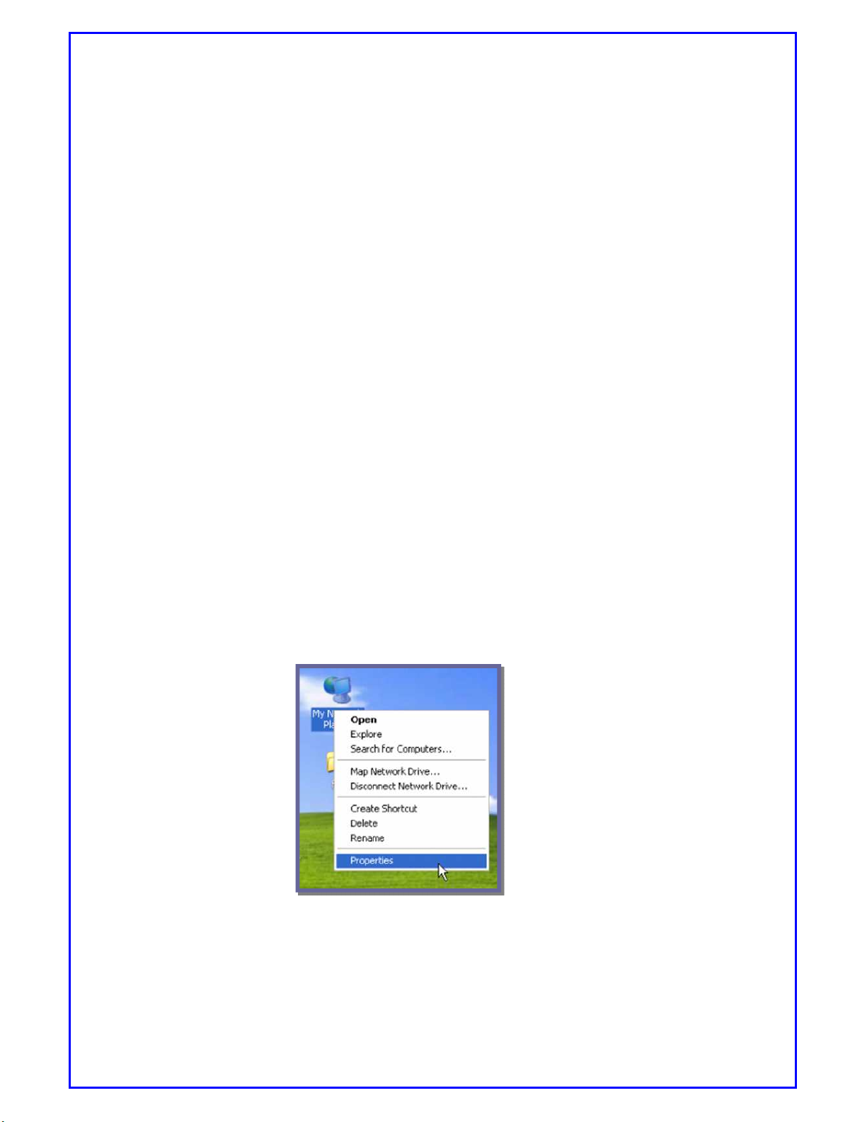
1. Take Windows XP as an example, to connect between PC and BC-3GM, point
cursor over “My Network Places” and click right button on your mouse, then
select [properties] in the menu.
[Picture 4.1: Step 1 of setting up your PC’s network environment]
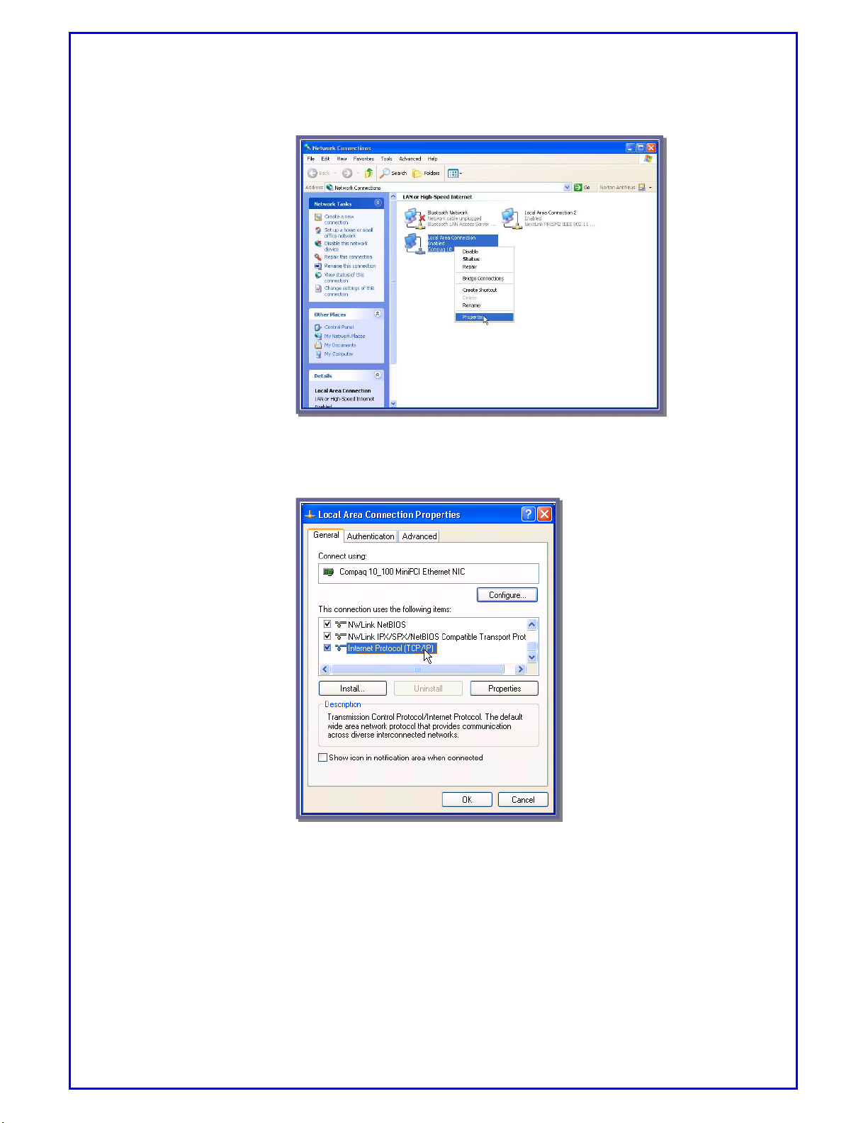
2. Check the “Local Area Connection” then click the right button on your mouse
then select [Properties] in the menu.
Page 13
BC-3GM User Manual Page 13 of 39
[Picture 4.2: Step 2 of setting up your PC’s network environment]
3. Go to “General” Tab, scroll down the right hand side bar until you see “Internet
Protocol [TCP/IP]”, then double click it.
[Picture4.3: Step 3 of setting up your PC’s network environment]
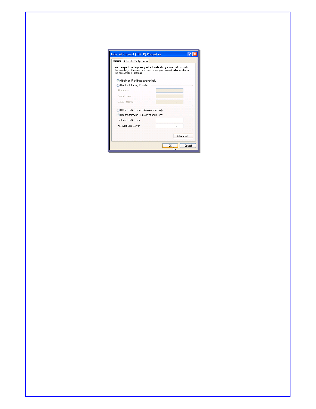
4. Check “Obtain an IP address automatically” then click the [OK] button.
Page 14
BC-3GM User Manual Page 14 of 39
[Picture 4.4: Step 4 of setting up your PC’s network environment]
5. After setting up Host PC, please connect a LAN cable between PC and BC-3GM,
then connect power cable between BC-3GM to power supply. Turn the power
switch on then you will be able to see LED “IP” is on soon.
5. ACCESSING WSU (WEB-BASED SETTING UTILITY)
5.1. How to access WSU
WSU (Web-based Setting Utility) will provide a web-based interface for users to
access and make configuration. This web-based configuration page just needs a
couple simple steps to setup.
1) Set up your PC’s network environment as automatically referring to “4.
SETTING UP YOUR PC ENVIRONMENT”
2) Connect the LAN and power cable on BC-3GM.
3) Launch the web browser on your PC then write IP address, https://192.168.0.1:
443/home.asp (Set by default). This router is designed for Security HTTP env
ironments. Port 443 accepts IE, Opera, Firebox.etc to access data under sec
ure environment.
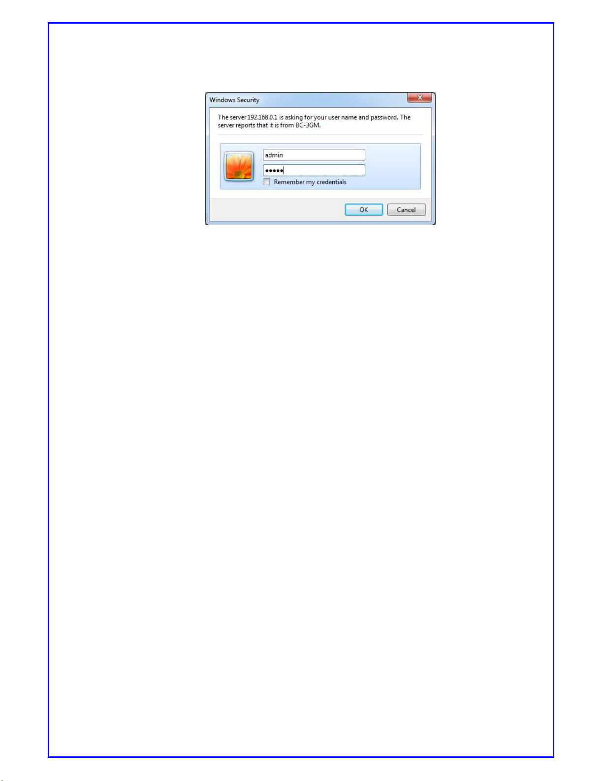
4) The pop-up window of login page appears.
Page 15
BC-3GM User Manual Page 15 of 39
[Picture5.1: Log-in window]
* Default setting is
User name: admin
Password: admin
You can change this option on [System config] .1page ->[SYSTEM]menu.
5) When you enter the correct information, you will access WSU.
5.2. How to configure WSU
When you finish configuration please click [Apply Changes] button, then
please reboot BC-3GM to make new setting effective.
Rebooting BC-3GM is a must. Click [REBOOT] menu, which will make new
settings effective.
6. CONFIGURATION OF INTERNET CONNECTION
6.1. Setting up your cellular environment
6.1.1. Accessing WSU
1) Access WSU referring to 5.1.1 How to access WSU
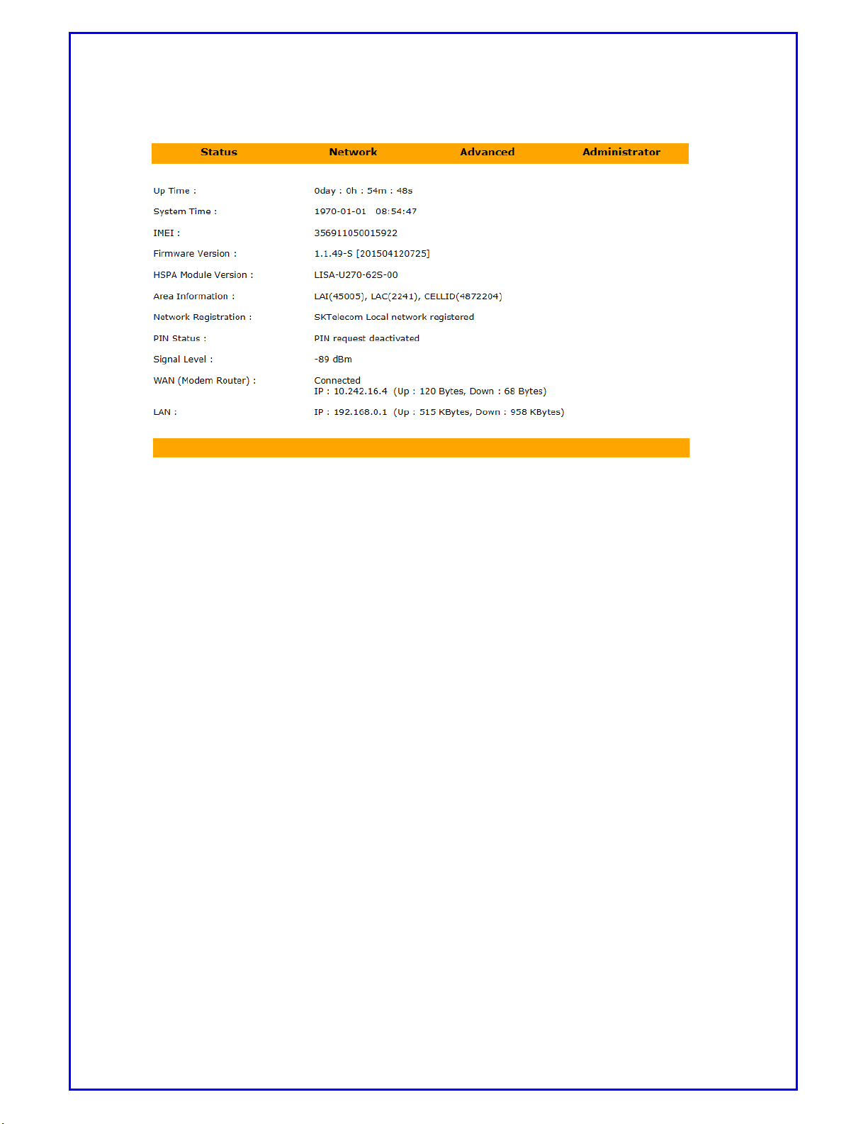
2) [Home] page will be shown as below picture.
Page 16
BC-3GM User Manual Page 16 of 39
[Picture 6.1: Home page of WSU]
Up Time: The time period that router has been ON.
IMEI: ID Number of router.
Firmware version: It shows which firmware version that router is running.
Area Information: It shows to which cell station that router is connecting.
PIN Status: It shows PIN status.
Signal level: This shows the signal strength. The higher value shows stronger
signal. For example -65dbM is better than -80dbm.
WAN: It indicates whether router is connected to network. If connected, it will
show IP address that has been assigned to this router. It also associates with
volume of data that has been uploaded or downloaded.
LAN: It shows IP address of this router within local network.
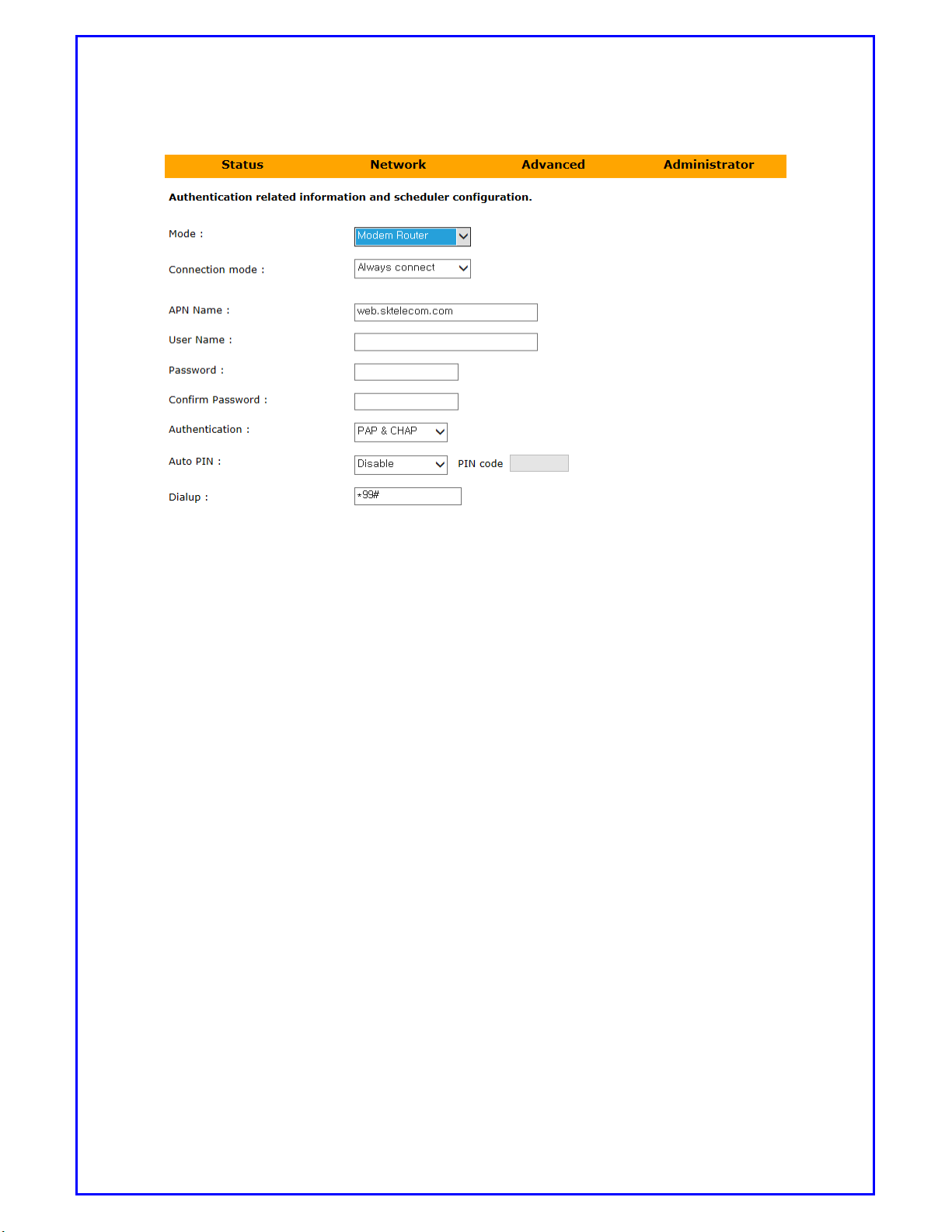
3) Select [Network] page then click the [WAN] menu.
Page 17
BC-3GM User Manual Page 17 of 39
[Picture6.2: Setting up WAN menu]
Mode: Modem router and Disabled are available to select. Default value
is Modem router
APN Name: It is provided by service provider to link to internet. For example,
in Australia, Telstra has a few different APN names. Please use correct one for
your service. Default value will be set as “internet”
Username: Username for your account if any.
Password: Password for your account if any.
Authentication: To choose PAP or CHAP or PAP & CHAP. Default is PAP &
CHAP.
Page 18
BC-3GM User Manual Page 18 of 39
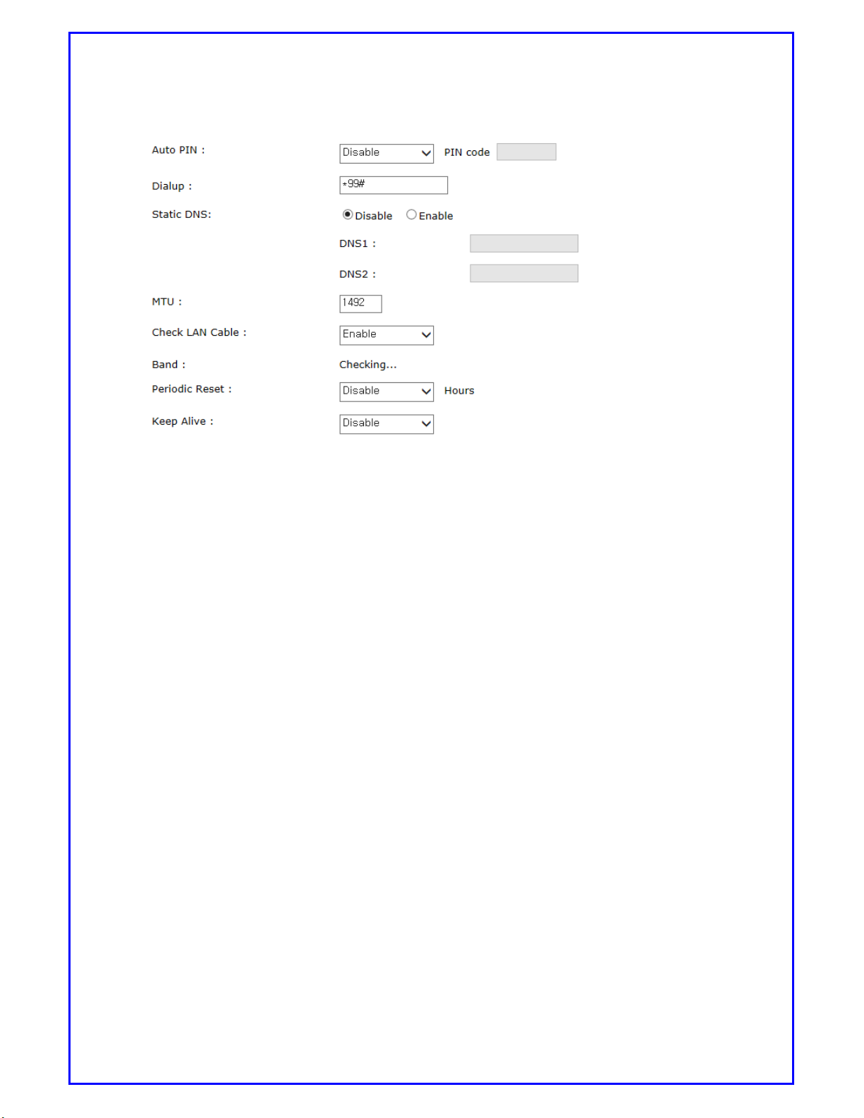
[Picture 6.3: Setting up WAN menu]
Auto PIN: To choose from Disable or enable. If you choose enable, Router
will enter PIN code automatically each time router is powered on.
Please keep your PIN code in safe place. If wrong code is entered for
3 times, SIM card will be locked by user. By this case, you will need to
ask service provider to provide PUK code to unlock your SIM.
Periodic Reset: Router will be reset according to preset timer. Value is from
1-24 hours. Default is Disable.
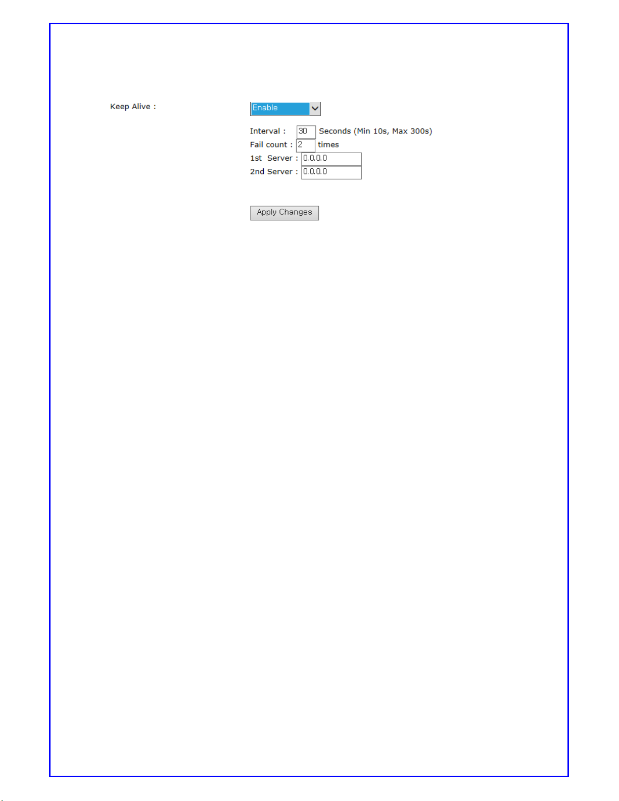
Keep Alive: This is to make sure that router is on-line all the time. If enable
is chosen, router will ping to private server with interval time and IP set by
user on 1st or 2nd or both server. When it fails, it will be counted as 1 time. If
count reaches preset times, router will be reset and re-connect again.
Page 19
BC-3GM User Manual Page 19 of 39
[Picture 6.4: Keep alive menu]
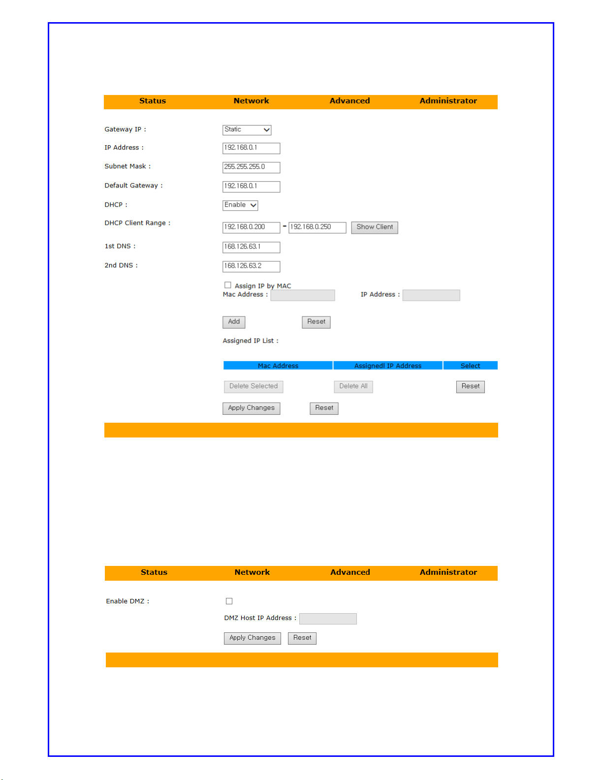
4) Select [LAN]
Gateway IP: Choose from Static or DHCP Client. If Static is chose, Router
will use static IP address shown on “IP address”. If choose DHCP Client,
Router IP address will be assigned by connecting host. Default to static.
IP Address: To assign IP address for Router. Default to 192.168.0.1
Subnet Mask: Default to 255.255.255.0
DHCP Client Range: This is the range that Router will assign IP address to
device which connects to this router. Default is 192.168.0.200-
192.168.0.250
1st DNS: To set up DNS address. Default is 168.126.63.1
2ndDNS: To set up DNS address. Default is 168.126.63.2
Assign IP by MAC: This is to prevent that devices link to router which may
be assigned by different IP address every time router power on or reboot. It
can be added up to 10 MAC address. The same MAC address cannot be assign
to different IP address.You can enter MAC address format as both 00-00-00-
00-00-00 and 00:00:00:00:00:00. And if router has entered MAC address
format as 00:00:00:00:00:00, it will change format to 00-00-00-00-00-00.
So you can see format as 00-00-00-00-00-00 only in list.
When you finish this setting, you must click [Apply change] button
Page 20
BC-3GM User Manual Page 20 of 39
[Picture 6.5: Setting up LAN menu]
5) Click [Advanced] then [DMZ]
This is to enable or disable DMZ function. If DMZ is Enabled, please enter DMZ
Host IP address. Default is disabled.
[Picture 6.6: Setting up DMZ menu]
Page 21
BC-3GM User Manual Page 21 of 39
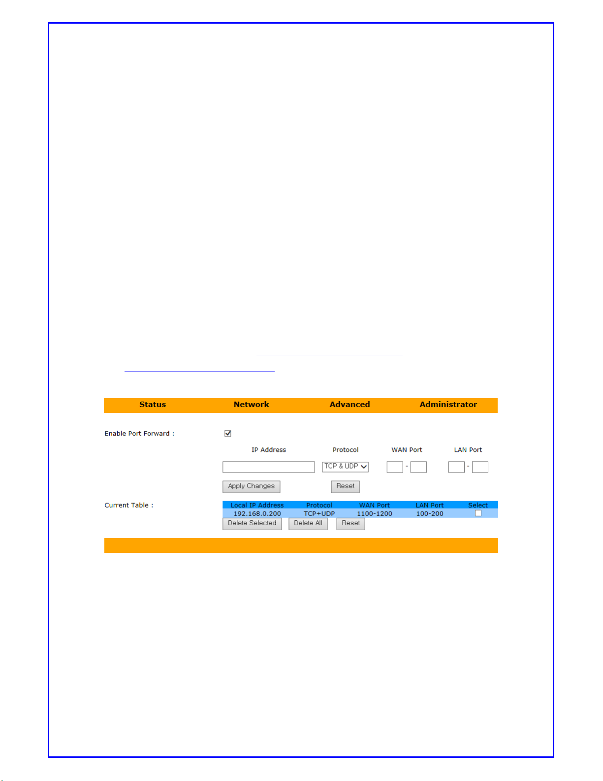
6) Click [Advanced] then [Port Forwarding]
If Port Forwarding is enabled, user can connect to device through Router.
For example, there are 2 pieces of network devices, Device A with IP address 1
92.168.0.200 with port 2010 and device B with IP address 192.168.0.211.
It can be set as picture below.
IP address: Type in device IP address.
Protocol: To choose from TCP, UDP or both.
Port Range: To enter port number or range.
Apply Changes: After Apply Changes is clicked, the setting will be added to Cu
rrent Port Forwarding Table.
After setup is done, since user is offering Dynamic IP most of the time, if you have
DDNS service, for example http://bc3gm.dyndns.org:1110 to see device A
and http://bc3gm.dyndns.com:1111 to see device B, you also can check
the Select checkbox then click Delete Selected or Delete All.
[Picture 6.7: Setting port Forwarding menu]
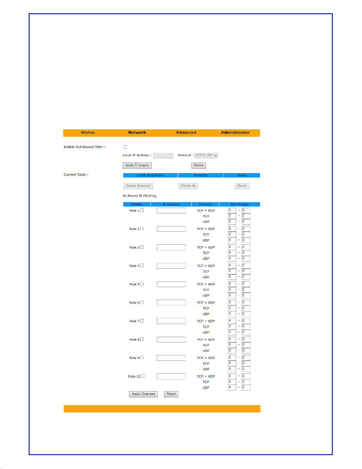
7) Click [Advanced] then [IP Filter].
IP filtering is to block un-wanted user either from local or remote side.
Out-bound IP Filtering: Enable this function will block all registered IP
address on Local network.
Page 22
BC-3GM User Manual Page 22 of 39
In-Bound IP Filtering: Enable this function will block all unregistered IP
address to send in packet. Only registered IP address can send in packet
under rule’s restriction.
Rule: If Rule is click, the IP address can send it packet.
Protocol: It can define to allow TCP, UDP or both to communicate.
Port Range: It specifies port number or range to accept.
Page 23
BC-3GM User Manual Page 23 of 39
[Picture 6.8: Setting up IP filtering menu]
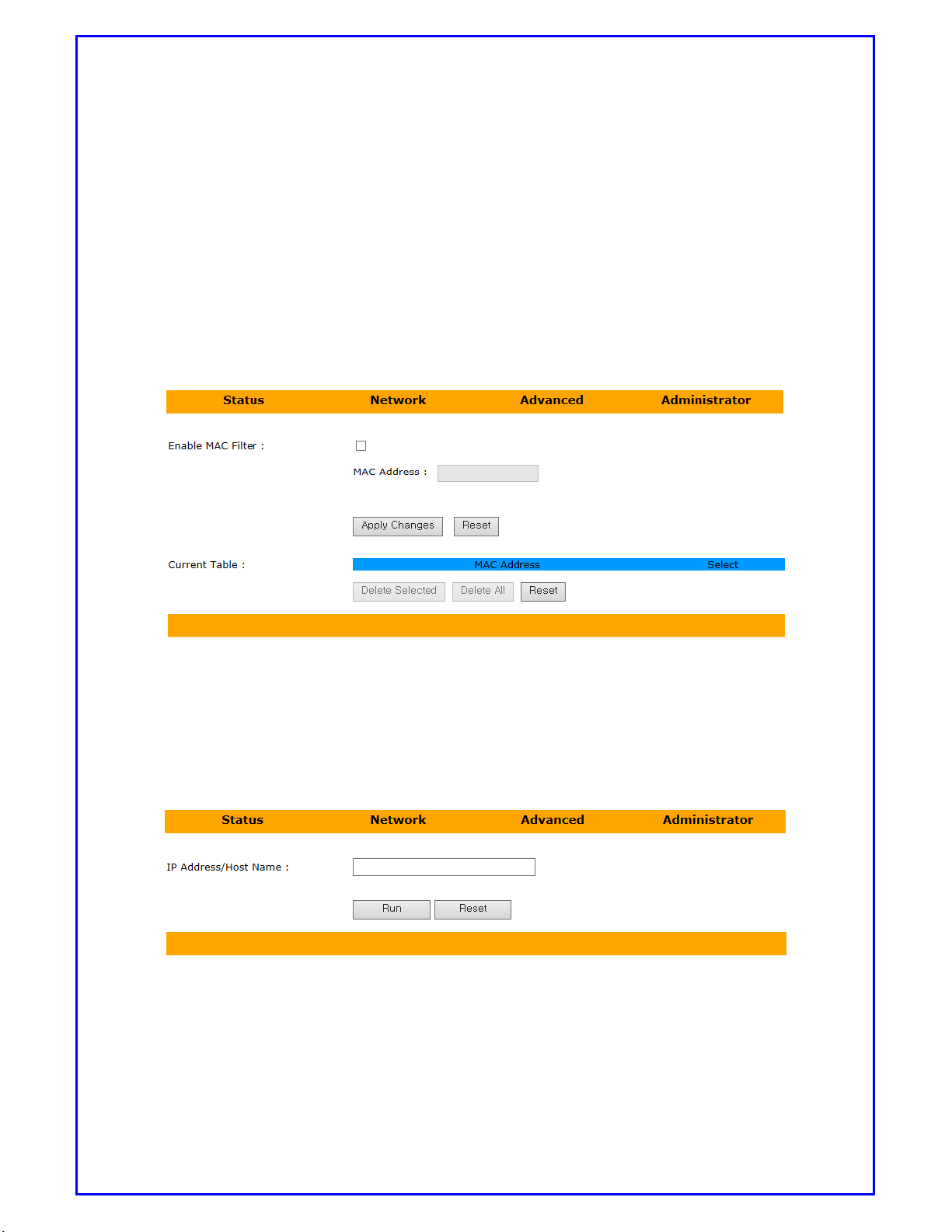
8) Click [Advanced] then [MAC Filter].
MAC Filtering: This is to block all un-wanted user if their equipment’s MAC
address is not registered.
If MAC Filtering is enabled, please enter MAC address and apply changes.
Only registered MAC address can access to this router.
[Picture 6.9: Setting up MAC Filtering menu]
9) Click [Advanced] then [Ping].
Ping: Enter IP address and click [Run], Router will ping this IP address and
show result.
[Picture6.10: Setting up Ping menu]
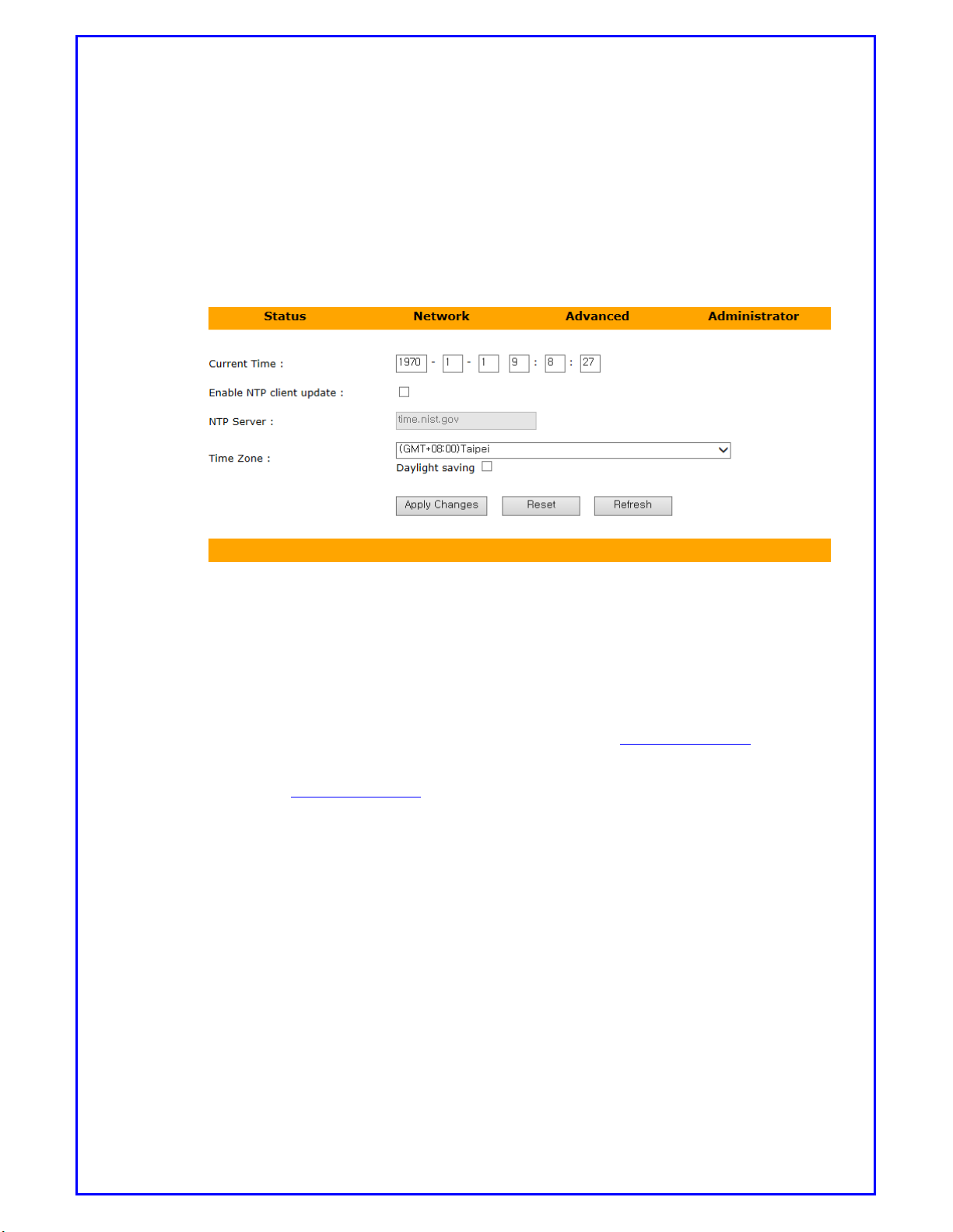
10) Click [Advanced] then [NTP].
This is to synchronize router timer with public time server.
Page 24
BC-3GM User Manual Page 24 of 39
Enter current time in the text box.
Enable NTP client update will synchronize to public time server. When router
is power on, it will link to NTP server and update the timer.
Time zone: To selection which time zone to use.
Daylight saving: Click if Daylight saving is in use.
[Picture6.11: Setting up NTP menu]
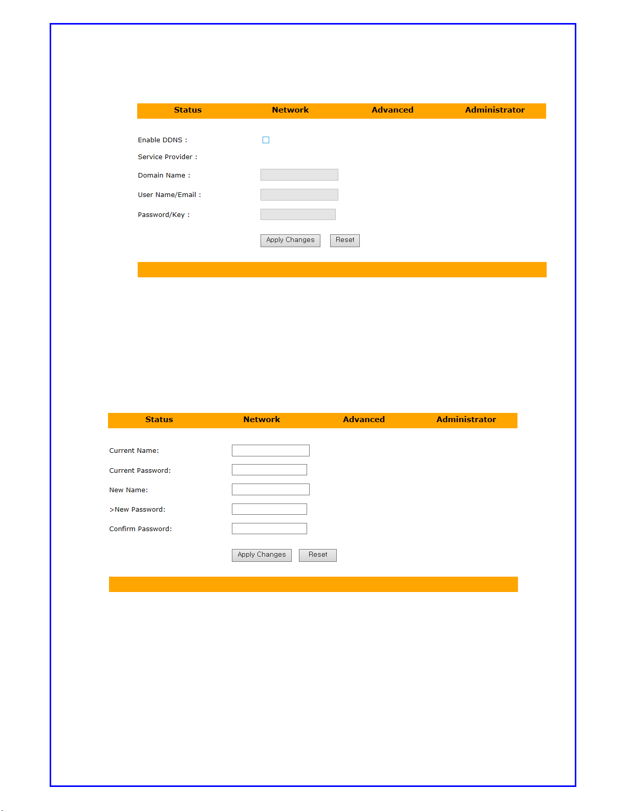
11) Click [Advanced] then [DDNS].
In most of case, user will assign Dynamic IP address to Router after it is connected.
This IP address changes all the time. To avoid tracing IP, Router can link to DDNS
service. For example, if you have applied a service from www.dyndns.com and
registered address is bc3gm.dyndns.com. Then each time when Router powers on,
it will register to www.dyndns.com. All you need is to type-in bc3gm.dyndns.com to
login this router.
When DDNS is enabled:
Domain name: Enter the name has been applied.
Username/E-mail: Enter user name or e-mail. This depends on your DDNS
service requirement. If it needs e-mail to login, then type-in e-mail address
only.
Password/key: Enter password or key
Page 25
BC-3GM User Manual Page 25 of 39
[Picture6.12: Setting up DDNS menu]
12) Click [Administrator] then [Password].
This section is for you to change name and password. When you login to Router,
you need to enter exactly the same information as you have entered.
[Picture 6.13: Setting up Password menu]
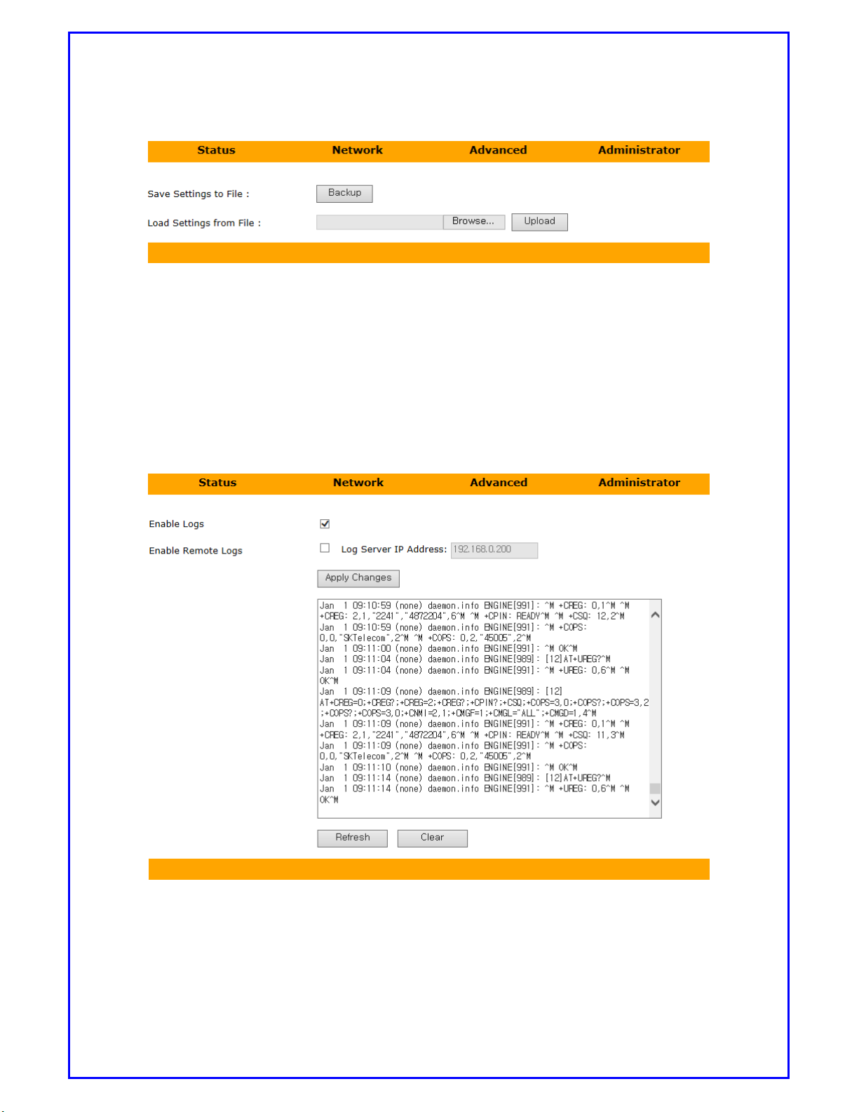
13) Click [Administrator] then [Password].
Save: Click Save, it will save current setting as file.
Load settings from File: Point to file location, click upload will load the
settings which has been saved
Page 26
BC-3GM User Manual Page 26 of 39
[Picture 6.14: Setting up Backup menu]
14) Click [Administrator] then [System Logs].
Enable log: Log file will shows on log screen.
Enable Remote Logs: Log file will send to remote address which shows on
Log Server IP Address.
[Picture6.15: System Logs menu]
The logs will be kept in flash but the maximum size is 1MB. If log file exceeds
maximum size, router will write a new log after deleting the old one.
Page 27
BC-3GM User Manual Page 27 of 39
You can see the old log in the system log page. If you enable remote log
You can see logs on the PC for remote troubleshooting or administration.
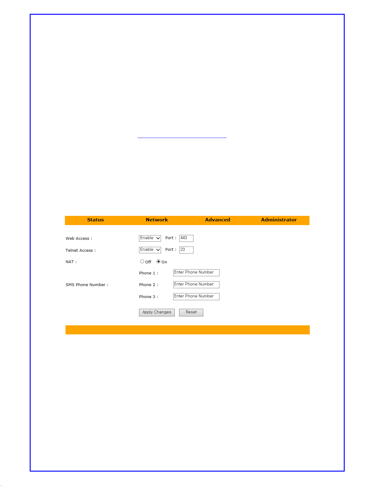
15) Click [Administrator] then [System].
This section is to setup Router system.
Web Access: Enable web access on port 443. When user needs to login,
Web address should be https://192.168.0.1/home.asp
Telnet Access: If Telnet Access is enabled, please specify which port is used
for Telnet. Default is port 23.
NAT: It is default as NAT router.
SMS Phone Number: If router received SMS “REBOOT” from registered phone
Numbers, Router will make reboot. It allows to register 3
different cellular phone numbers.
[Picture 6.16: Setting up System menu]
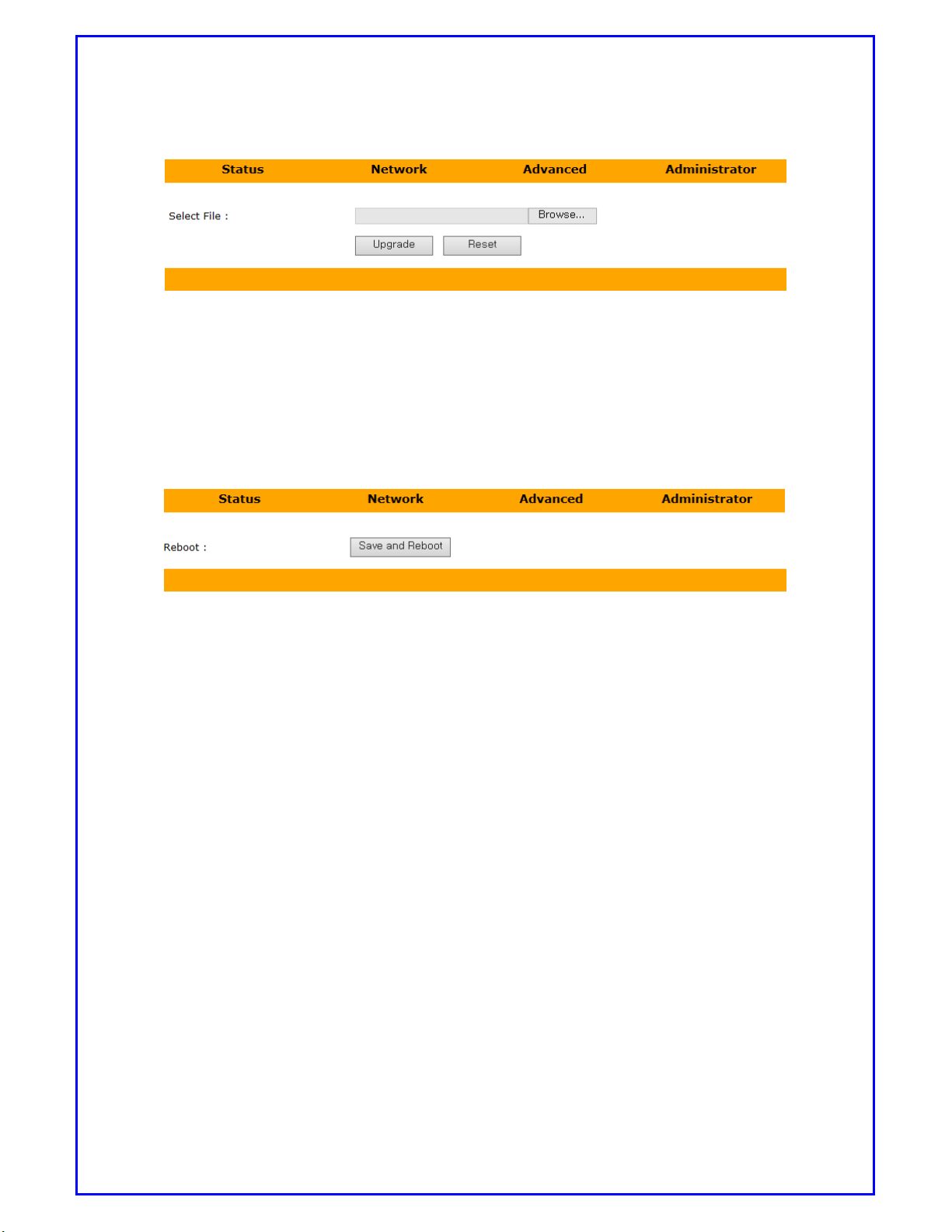
16) Click [Administrator] then [Upgrade].
Router can be updated either from local network or remote PC.
Select file: Point to new firmware location, then click [Upgrade].
Router will upgrade to new firmware. During upgrade procedure, please remain
power on all the time until upgrade is complete finished.
Page 28
BC-3GM User Manual Page 28 of 39
[Picture 6.17: Setting up Update menu]
17) Click [Reboot].
Reboot: When Reboot is clicked, it will pops up a dialog box for Save current
setting and reboot. Click OK, router will save settings and reboot.
[Picture 6.18: Setting up Update menu]
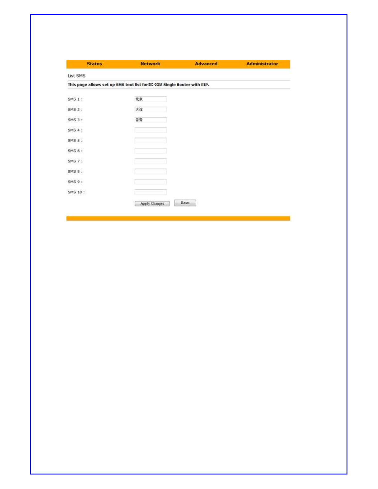
18) Click [Administrator] then select [EtherNet/IP SMS].You can define up to
30 SMS messages in Chinese on this web page. These predefined SMS
messages can be sent to the specified phone number through EtherNet/IP
service or Modbus TCP command. This chapter will describe how to configure
EtherNet/IP parameters and RSLogix5000 tags for SMS text messaging.
Page 29
BC-3GM User Manual Page 29 of 39
[Picture 6.19: EIP SMS configuration menu]
*Please be noted that each Chinese SMS messages contains up to 80 Chinese
characters, each English SMS messages contains up to 160 ASCII characters.
7.
CONFIGURATION GUIDE For PLC
7.1. Rockwell/Allen-Bradley PLC Configuration
7.1.1. Configuration Guide
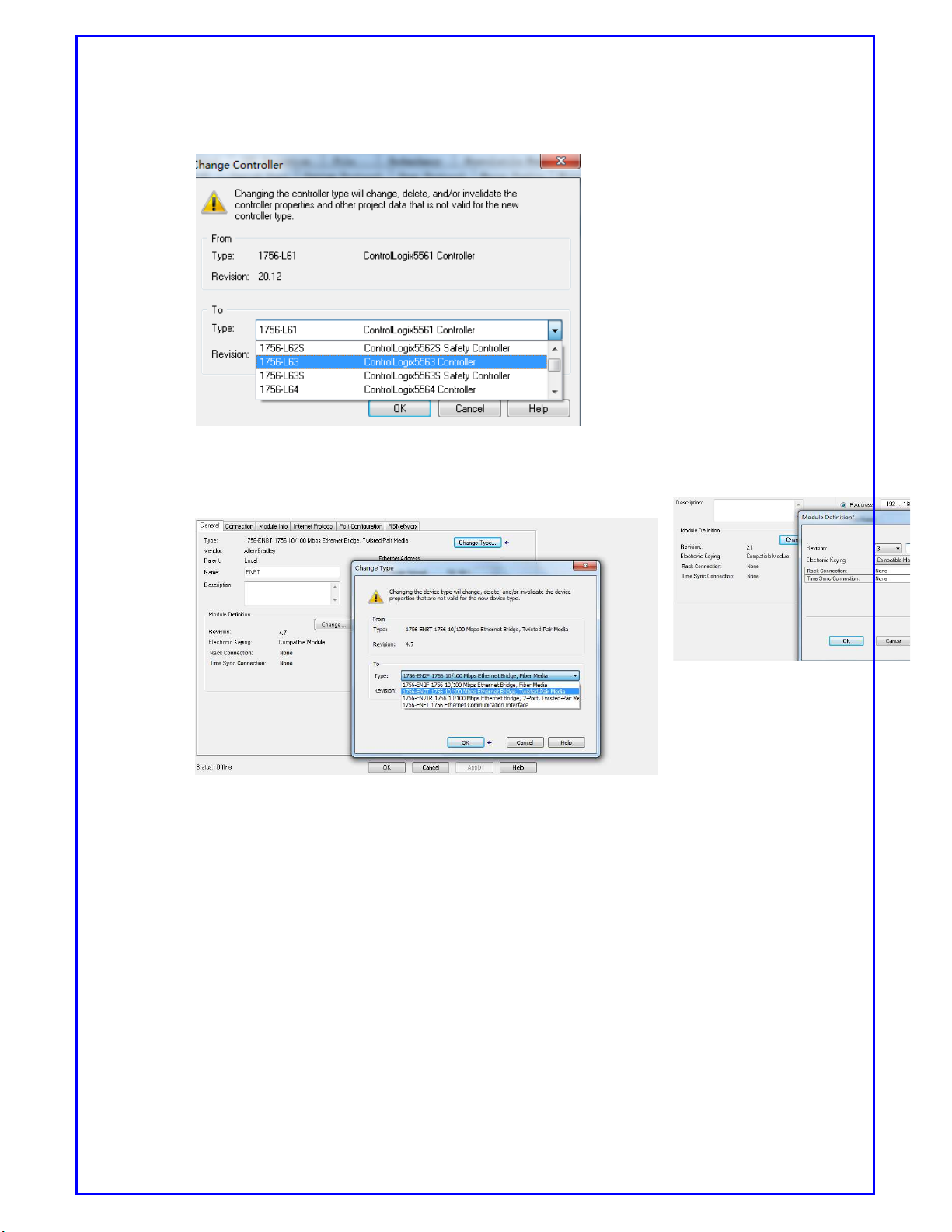
1) Create a new RSLogix5000 project, select controller type from drop-down list.
Page 30
BC-3GM User Manual Page 30 of 39
[Picture7.1: Change Controller]
2) Create an Ethernet module and edit device type and revision information.
[Picture7.2:Change
device type and
revision]
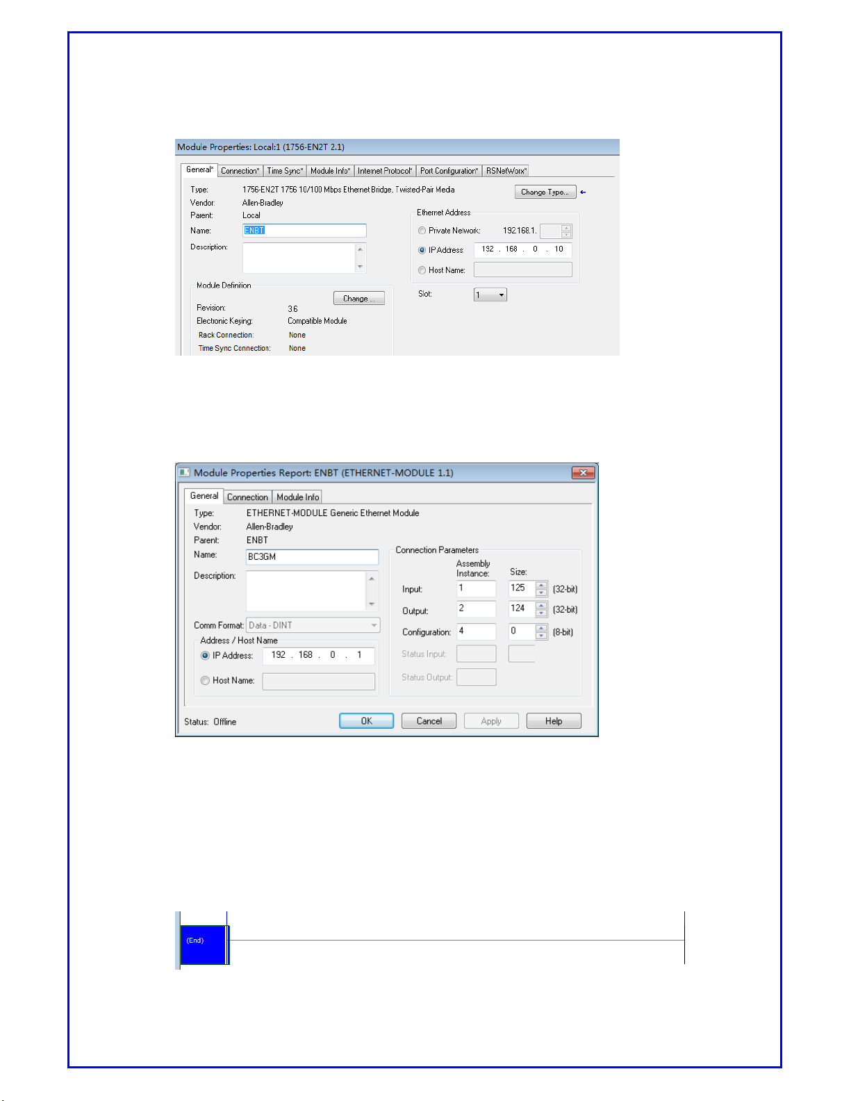
3) Under Module Properties, General tab, change IP Address as shown below.
Page 31
BC-3GM User Manual Page 31 of 39
[Picture7.3: Change IP Address]
4) Create a module named BC-3GM,select module type as Ethernet-Module Gen
eric Ethernet Module, modify IP address as 192.168.0.1。
[Picture7.4: Create BC-3GM module]
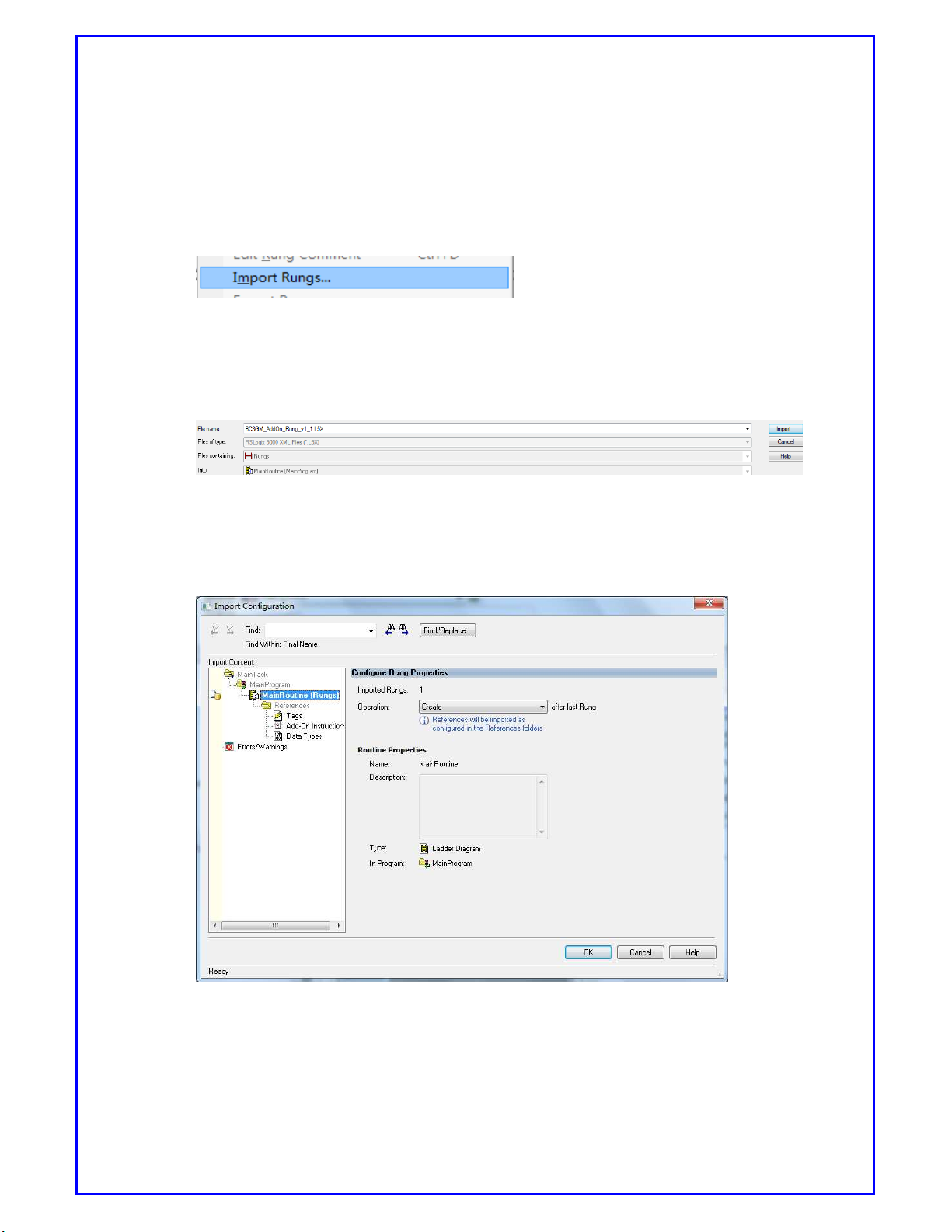
5) Import an Add-on program for BC-3GM_AddOn_Rung_v1_1.L5X
a) In the Controller Organization window, expand the Tasksfolder and subfolde
r until you reach the MainProgram folder.
b) In the MainProgram folder, double-click to open the MainRoutine folder.
Page 32
BC-3GM User Manual Page 32 of 39
[Picture7.5: Open MainRoutine folder]
c) Select an empty rung in the routine, and right click to open a shortcut me
nu. On the shortcut menu, choose Import Rungs.
[Picture7.6: Import Rungs]
d) Navigate to the location where you save the BC-3GM_AddOn_Rung_v1_1.L
5X, select it and click Import.
[Picture7.7: Locate rungs]
e) Click OK to confirm the import.
[Picture7.8: Complete the configuration]
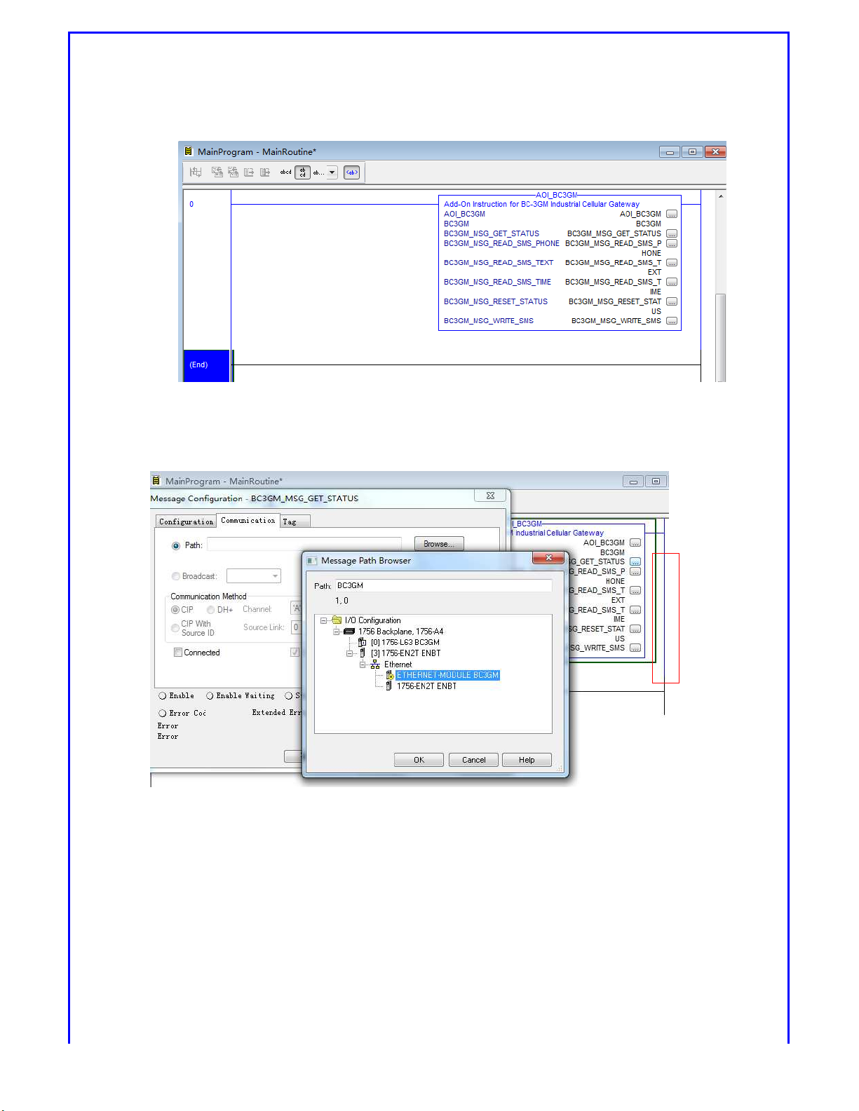
6) Modify pointer for all M SG (except AOI_BC 3GM) as il lustrated belo w.
Page 33
BC-3GM User Manual Page 33 of 39
[Picture7.8: Modify Pointer]
* Please be noted that ETHERNET-MODULE BC3GM is the BC-3GM module.
[Picture7.9: Ethernet Module BC3GM]
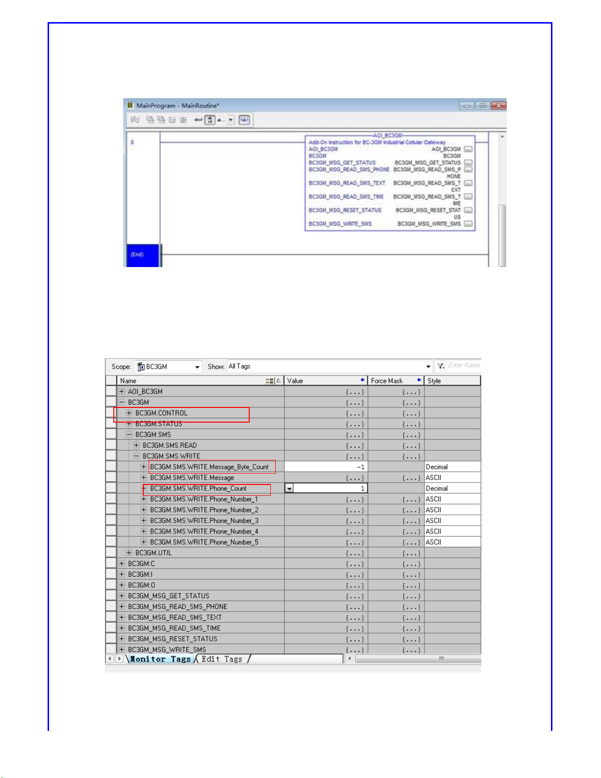
7) Setup the communication paths for the AOI_BC3GM instruction after imp
ort the sample rungs. The AOI_BC3GM instruction implements 6 function
s. Setup the communication path for each function by clicking the button
'...' of the AOI_BC3GM instruction.
Page 34
BC-3GM User Manual Page 34 of 39
[Picture7.10: Message Configuration]
8) Set up the number of phones to receive SMS messages by writing a value t
o the tag BC3GM.SMS.WRITE.Phone_Count. The default value is 1. The maxi
mum value is 5.
[Picture7.11: Setup cellphone count]
Page 35
BC-3GM User Manual Page 35 of 39
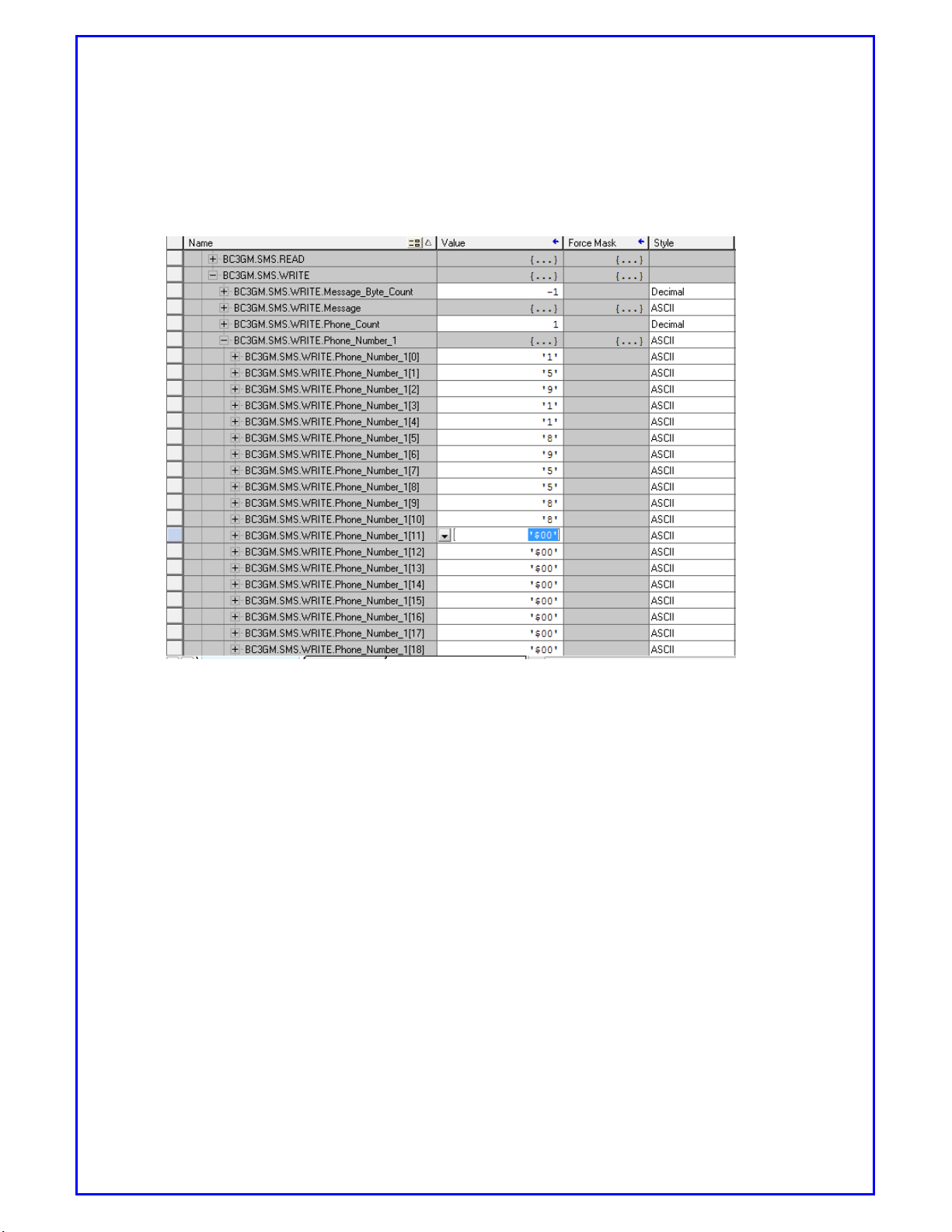
9) Set up the cellphone number in the tag BC3GM.SMS.WRITE.Phone_Number_x,
ended by R$00.P
[Picture7.12: Setup cellphone number]
10) Send SMS text in Chinese using EtherNet/IP
Below are the steps how to send the predefined SMS messages.
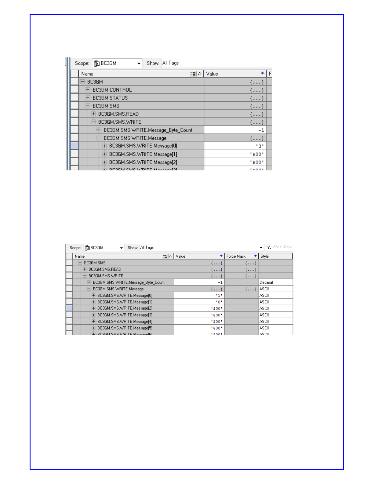
Set BC3GM.SMS.Write.Message_Byte_Count as -1.
Fill BC3GM.SMS.Write.Message with the sequence number of
predefine SMS messages. The sequence number is stored as a
null-terminated string format. a null-terminated string is a
character string stored as an array containing the characters and
terminated with a null character (‘$00’).
Page 36
BC-3GM User Manual Page 36 of 39
[Picture7.13: Predefine SMS messages]
11) If you would like to send the predefined SMS 10, the data of the BC3GM.S
MS.Write.Message tag will be filled with a null-terminated string “10” (BC3G
M.SMS.Write.Message[0] = ‘1’, BC3GM.SMS.Write.Message[1] = ‘0’, BC3GM.S
MS.Write.Message[2] = ‘$00’)
[Picture7.14: Send predefine SMS messages]
12) Send English SMS text using EtherNet/IP
If you would like to send an English SMS message directly, please write the
message content into the BC3GM.SMS.Write.Message tag and set the
tagBC3GM.SMS.Write.Message_Byte_Count as the SMS message length.
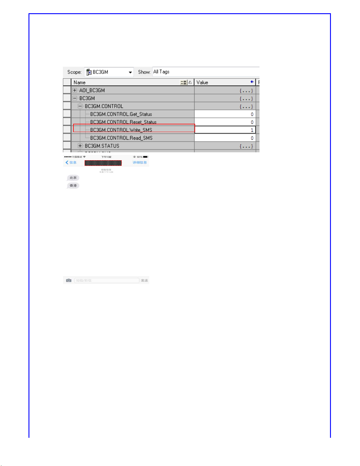
13) Set CONTROL.WIRTE_SMS as 1, message will be sent to targeted cellphone.
Page 37
BC-3GM User Manual Page 37 of 39
[Picture7.15: Send predefine SMS messages]
7.2. Using MODBUS TCP command Send SMS
7.2.1. Overview
This port is for manufacturer use only. The console is designed mainly for diagnostic
data reading. Normally this port is for debugging.
The BC-3GM supports 5 concurrent Modbus TCP/IP connections to
read/write radio diagnostic and generic SMS data.
BC-3GM supports sending both English and Chinese SMS messages
through MODBUS TCP command to specified phone number
BC-3GM supports Modbus function FC6 and FC16 used by Siemens and
Schneider users to send 142 SMS transit messages, however totally 2
Page 38

BC-3GM User Manual Page 38 of 39
commands FC16 will be necessary to complete this since Modbus itself
allows the data access to up to 125 registers for each command.
7.2.2. SMS message parameter
The Modbus TCP server listens to 502 port and 2000 port. It can
support the following Modbus functions.
FC6= Preset (Write) Single Register (4X)
FC16= Preset(Write) Multiple Register(4X)
SMS Message Parameters
Name Data Type Access
Modbus
Register
Out_Str_Size INT Read/Write 40011
Num_To Send INT Read/Write 40012
40013-
Output_Str SINT[160] Read/Write
40092
40093-
Ph_Number_1 SINT[24] Read/Write
40104
40105-
Ph_Number_2 SINT[24] Read/Write
40116
40117-
Ph_Number_3 SINT[24] Read/Write
40128
40129-
Ph_Number_4 SINT[24] Read/Write
40140
40141-
Ph_Number_5 SINT[24] Read/Write
40152
Description
Number of bytes in the Output
String
Number of phone numbers that
the SMS will be sent to
Message to be transmitted (Max
160 Bytes)
full number including prefixes
country code etc..
full number including prefixes
country code etc..
full number including prefixes
country code etc..
full number including prefixes
country code etc..
full number including prefixes
country code etc..
[Table7.1: Modbus TCP SMS message parameters]
Please be noted that it is very critical to predefine Chinese SMS messages ahead to
enable sending Chinese SMS messages. In this brochure, Page28, it describes how
to setup up to 30 Chinese SMS messages and each text message contains up to 80
characters. The predefined content will be the final received message in cellphone.
Output_Str parameter sent by Modbus command is actually the sequence number
Page 39

BC-3GM User Manual Page 39 of 39
of predefined Chinese SMS messages.
8. INFORMATION OF SMS FUNCTION IN HSPA ROUTER
8.1. DSR.REBOOT
If router receives this message D S R .REBO OT, router will reboot and display
"Router will reboot now. Please wait…”.
8.2. DSR. NETINFO
If router receives this message DSR.NETINFO, router will display network
information following format as:
<SIM No.><IP>,<APN>,<ID>,<Password>,<Authentication>,<Signal>
Example:
Received Message: DSR.NETINFO
Responded Message: SIM:1,192.168.0.1,internet,meter,meter,
PAP and CHAP,55
8.3. DSR.PPP = (ON or OFF)
If router receives this message DSR.PPP = (ON or OFF), it will get router get
online or offline. "SMS connection" option must be enabled in WAN page before
using PPP connection
Example 1 Send Message: DSR.PPP=ON
Receive Message: PPP Connection: Trying to make a PPP
connection
Example 2 Send Message: DSR.PPP=OFF
Receive Message: PPP Connection: Disconnected
 Loading...