

Specications
Input Level MIC setting: -36 dBu ideal
LINE setting: -10 to +4 dBu ideal
Output Level Nominal MIC levels
Frequency Response 20 Hz to 20 kHz (+/- 3dB)
Phantom Power Dual regulated 48 volt power supplies
Current to 14 mA (direct short)
Level Meter Calibrated from -54 dBu to -33 dB
Battery Type One 9 volt alkaline battery
Battery Duration 3 hours typical with both phantom
switches enabled
No power required to pass signal
Dimensions 6” x 3” x 1.7” (L x W x H)
(152 mm x 75 mm x 43 mm)
Weight 16 oz (0.45 kg)
Limited Two Year Warranty
This warranty covers any defects or malfunction in your new BeachTek adapter
for two years from date of purchase.
BeachTek will replace or repair any defective or malfunctioning adapter, within
the warranty period, at no charge. The warranty does not cover damage
resulting from accident, alteration, misuse or abuse. The device must be sent to
our service center at your expense.
Should you require service please contact us rst before returning the unit to
us. Return instructions can be found on our website at www.beachtek.com
under the Support option.
Upon receiving the returned adapter it will be inspected and replaced or
repaired if found defective. The unit will be shipped back to you within ve
business days at our expense.
BeachTek Inc.
1855 Kirschner Rd. Suite 230
Kelowna, British Columbia
Canada V1Y 4N7
tel (416) 690-9457
email info@beachtek.com
web www.beachtek.com
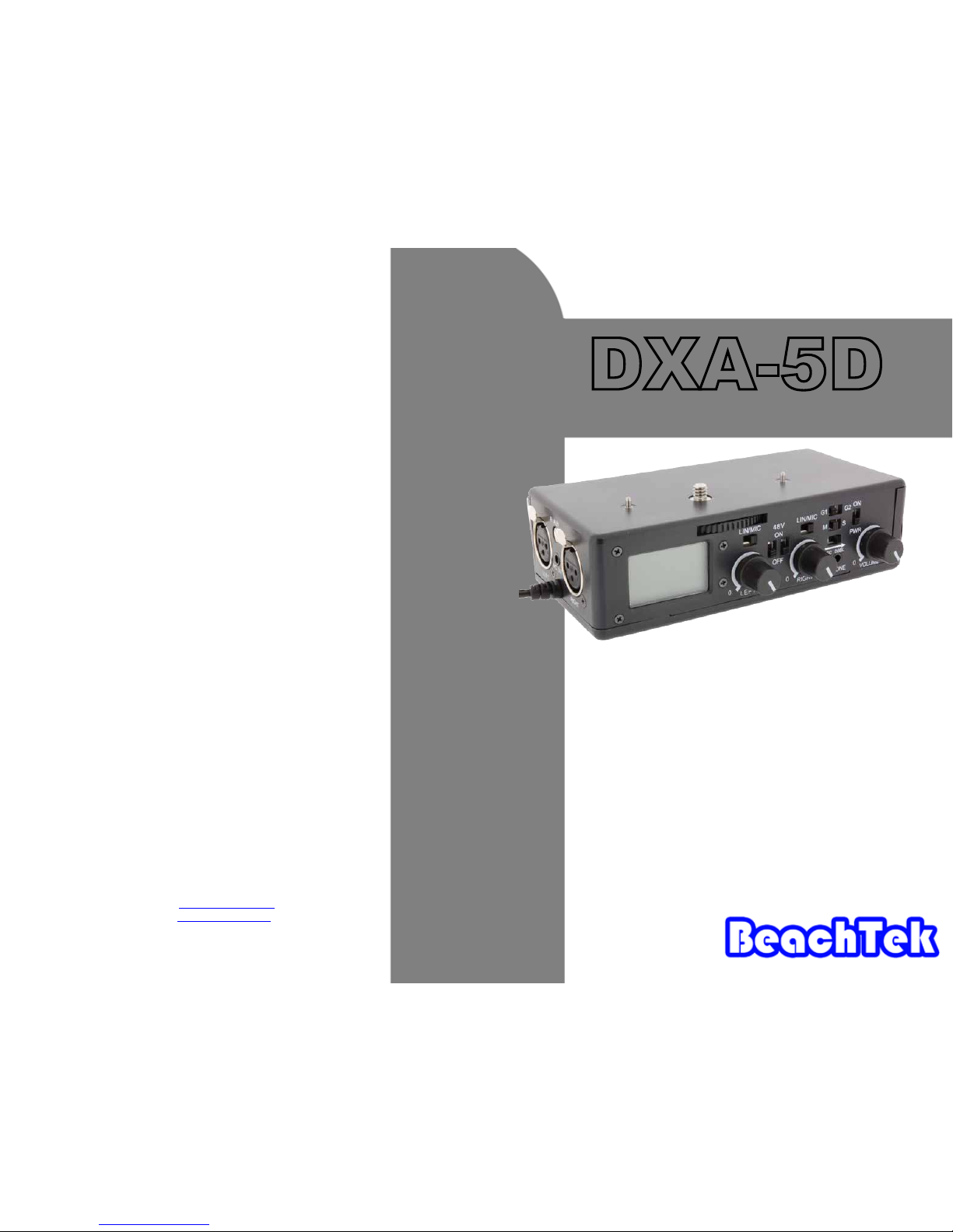
DXA-5D
Operating Instructions for the DXA-5D Adapter
• Before using this high quality device, please read this
operating manual thoroughly to obtain the highest performance.
• Please contact us if you have any problems or questions.
The BeachTek DXA-5D is a two-channel, transformer balanced XLR
adapter for attaching external microphones and other audio gear to
the Canon 5D Mark II camera. It can also be used with any camcorder or other audio recording device that has a built-in mic jack.
The DXA-5D is very easy to set up and use. It allows you to connect
a wide variety of audio devices including professional condenser
microphones that require 48 volt phantom power to operate. The
built-in level meters show the input signal strength at a glance while
the trim controls allow you to adjust the input level for optimum
recording. The headphone jack lets you monitor the audio that is
coming out of the adapter. The DXA-5D uses high quality balancing
transformers, which are completely noise free for superb audio.
The adapter mounts to the bottom of the camera and can also be
mounted to any standard tripod.
©2009 BeachTek Inc.

Using the AGC DSBL Feature
This switch is a means to disable the wild swings of the Auto Gain Control in the camera. It activates
an inaudible tone of 20 kHz to the left channel (when set to STEREO operation) that prevents the Auto
Gain Control from increasing the gain to its maximum level. This reduces the hiss that normally occurs
when the camera is recording audio during quiet moments. The tone is recorded by the camera but can
be easily ltered out if necessary. You can still use the left channel for recording normal audio at the
same time as the AGC DSBL feature is active.
You may also want to record audio only on the right channel and leave the left channel unused for the
AGC control signal if this tone presents a problem down the line. In this case, you should set the M/S
switch to S for stereo to keep the AGC signal separated from the recorded signal. Again, it is important
that you do a test recording and play back the audio to see if it is acceptable.
The AGC DSBL feature will lower the gain on the camera, which will require a sensitive microphone for
best results.
Before You Begin
1) These instructions refer to the use of this adapter with the Canon 5D Mark II camera
unless otherwise noted.
2) It is important that you use a sensitive microphone with the adapter to get the best
performance when recording audio on the Canon 5D Mark II.
3) Do a few test recordings and check playback on the camera to be sure that the audio is
captured as expected. Since there is no output audio jack on the camera, there is no way to
ensure that what you are monitoring is being recorded by the camera.
4) The audio that you hear from headphones connected to the phone jack on the
adapter is not exactly the same as the audio you will hear on play back from the camera.
5) Note that you cannot monitor audio on playback through this device.
6) Please read and understand the use of the AGC DSBL feature before using this function.
Setup Guide
Battery Installation
1.) The DXA-5D operates on one 9 volt battery. We recommend that you
use either an alkaline or lithium for longest operating time.
2.) The adapter only requires battery power for supplying phantom power and operating the LCD panel
AGC disable feature and headphone amplier. No power is required to pass the audio signal.
3.) To install the battery simply open the cover by pushing on the end of the cover to unclip it.
Insert the battery with the “+” positive terminal lined up with the “+” indicator on the battery
compartment. Replace the battery cover.
Mounting the Adapter on the Camera
1.) Line up the locating pins on top of the adapter to the holes on the underside of the Canon
5D Mark II camera. Carefully turn the top mounting knob to the right to screw the adapter
squarely into the camera. If you are using this adapter on another camcorder, you can
remove the top two locating pins.
2.) Connect the output cable to the camera’s MIC jack.
3.) You can also mount the adapter to any standard tripod.
Initial Setup
1.) Connect your microphones or other audio gear to the adapter via the XLR inputs or AUX
mini-plug input.
2.) Set the LIN/MIC switch to either MIC when connecting microphones or most wireless
receivers, or to LIN when taking a line level feed from a mixing board.
3.) Set the G1/G2 switch to G1. You may have to change this to the G2 setting if you
encounter any ground loop noise when attached to a mixing board. You will need to do a test
recording and playback to determine the best position for your setup.
4.) Set the M/S switch to M for mono when using one microphone. Set the unused channel
trim control fully clockwise so that it does not interfere with the working channel. When using two
microphones, you should normally set the switch to S for stereo to keep each channel separated.
5.) Set the AGC DSBL switch to the left so that it is deactivated.
6.) Set the LEFT and RIGHT trim controls about half way to start.
7.) Plug your headphones into the PHONES jack to monitor the audio. Be sure that the VOLUME
control is set low to avoid excessively loud audio from damaging your hearing.
8.) Turn on the PWR switch on the DXA-5D.
9.)Activate the 48V phantom power switch for only those microphones that
require 48 volt phantom power to operate.
Basic Operation
After following the above Initial Setup, you should be ready to start recording.
1.) Use the level meters on the adapter to monitor the signal levels from your sound source.
2.) Adjust the LEFT and RIGHT trim controls to give you a peak reading of -36 dBu on the
level meter. This is the “sweet spot” for getting the highest signal to noise ratio from the
camera. The closer you are able to get to this reading, the less hiss you will get from the
camera preampliers. If you are not able to reach this level, then you should try moving
the microphone closer to the sound source or switch microphones to a more sensitive model
for better results. Normally, you will simply leave both trim controls at full clockwise or
maximum position for no attenuation.
3.) Adjust the VOLUME control for the headphones to a comfortable listening level.
4.) Do a test recording and play back the audio to determine if the captured audio is acceptable. Note
you will not be able to monitor the playback audio from the adapter.
5.) The Auto Gain Control (AGC) in the camera will vary the amount of gain depending upon the input
signal level. During quiet moments, the AGC will increase the gain, which will also increase the amount
of hiss from the camera preampliers. See “Using the AGC DSBL Feature” to reduce this problem.
Adapter Controls
PWR
Provides power to the phantom power supplies, LCD meter, AGC disable feature and headphone
amplier. Power is not required to pass the audio signal.
48V
If your microphone requires 48 volt phantom power to operate, rst connect the microphone to the
adapter. Activate the PWR ON switch and then the 48V switch for the channel it is connected to. Do
not activate phantom power for dynamic microphones, condenser microphones that do not operate on
phantom power, wireless receivers, mixing boards or any unbalanced device as it may cause damage to
both the adapter and connecting device.
LIN/MIC Switches
When connecting a microphone to either channel of the DXA-5D, set the corresponding LIN/MIC switch
to MIC. When connecting a line level output from a mixing board or sound board set the switch to LIN to
activate a 40 dB pad. This attenuates the line level signal to the proper level so that it does not overdrive
the input of the camera.
LEFT and RIGHT Controls
Each channel has a trim control that attenuates the input signal from unity to no output. Adjust each trim
control to give you a maximum reading of -36 dBu on the level meter of the adapter. This will give you
the ideal recording level for best signal to noise ratio.
M/S Switch
The M (MONO) setting mixes both channels together and sends the audio to both the right and left
channels, which is ideal when only one microphone is being used. Be sure to keep the trim control
for the unused channel fully clockwise so that it does not interfere with the working channel. The S
(STEREO) setting keeps both channels separated and should normally be used when two microphones
are connected. This provides two discrete channels of audio.
Volume Control
This adjusts the headphone volume level for monitoring the audio. Be sure to adjust the control for a
comfortable listening level to avoid hearing damage.
PHONES
This jack lets you connect headphones to monitor the audio coming out of the adapter. Note that it does
not monitor the audio coming out of the camera. Audio is only heard during recording – it will not allow
you to listen to the playback audio.
G1/G2 Switch
Set the G1/G2 ground switch to the position that gives you the least amount of noise. This should
normally be set to G1 for use with the Canon 5D Mark II. This switch allows the input and output grounds
to be isolated to reduce ground loops when connected to AC powered mixing boards. A record and
playback test should be done to determine the best setting for your setup.
LEFT and RIGHT XLR Inputs
The two balanced XLR inputs attach to professional microphones or other audio gear such as mixers
and sound boards.
R AUX Input
The unbalanced input is ideal for connecting to a wireless receiver that has a mini-plug output cable.
This sends the signal to the right channel. Be sure to disconnect any cables plugged into the right XLR
input when using the AUX input.
Output Cable
The attached shielded cable terminates in a gold plated, stereo mini-plug connector. Plug this into the
microphone jack on your camera.
MIC OUT
This stereo output jack is ideal for connecting an auxiliary audio recording device. The output level is a
nominal MIC level.
AGC DSBL
This switch provides a xed high frequency tone of about 20 kHz into the left channel of the camera to
tame the wild swings of the Auto Gain Control in the camera. This reduces the hiss from the camera
preampliers that occur during quiet moments of the recording. This tone is recorded by the camera, but
is inaudible and can also be easily ltered out.
LCD Display
The back lit display shows the level meters, battery indicator and position of the various switches on the
adapter.
 Loading...