

Page 1
DESCRIPTION
SPECIAL
FEATURES
TECHNICAL
SPECIFICATIONS
FUNCTIONNAL
DESCRIPTION
This interface system has been developed to be the link between a programmable controller and a 16
Microcell-type beam. This system simplifies the wiring of the beams and reduces the number of
connections to the controller by using an RS485 intelligent communication. The control of the beams
being entirely in the hands of the interface system, the controller is free for other duties.
MULTIBEAM USER'S GUIDE
The product is composed of two modules: one controlling the emitters, the other controlling the
receivers and the communication. The decentralized connection between the emitters and the
receivers simplifies the heads wiring.
Easy connection between the product and the controller : 4 wires are enough for the power supply
and the communication ;
Half Duplex RS485 communication port well adapted to industrial environments ;
Transmission speed selection : 9600 or 19.200 bps ;
Possibility to choose between ASCII bus mode or quick mode ;
Possibility to connect up to 4 interface systems on the same communication bus ;
Response time of the beams without frame transfer time : < 20 ms ;
Detection of short-circuit on the receivers (only possible on quick mode) ;
Control LED on the emitting module ;
Status of the beams visualized by red LEDs on the receiving module ;
Low current consumption : <100 mA under 12 to 24 Vdc ;
3.5mm pitch Plug connector to make the pre-wiring and the maintenance easier ;
Extruded profile aluminum housing, solid and easy to install ;
Each beam is fit out with a plug connector to make the pre-wiring easier ;
Product complying with the EC norms in force ;
Possibility to increase the beam range up to 6 meters on request.
Microcell
Technology :Active infrared + microprocessor
Maximum range : 1.5m
Distance between beams : 20cm minimum
Beam aperture half-angle : 8°
Sunlight immunity :
• 75.000 lux at an angle of 8°
• 20.000 lux in the axis
Temperature range : -20°C à +55°C
Detection head sealing : IP65(DIN40050)
Dimensions cylindrical heads :
•••• body : 10mm (embedded Length)
12.4mm (diameter)
• collar : 15.6mm
Housing colour :ABS black.
Weight of a single head :2 g
Heads cable colours :
• emitter : grey / blue (or yellow / black) ;
• receiver : black / blue (or green / black).
Cable colours :
• emitter : grey (or yellow) ;
• receiver : black (or green).
Control boxes
Technology : RISC microprocessor
Supply voltage :12 - 24 VDC +/-10%
This product has been developed to control 16 Microcell-type IR beams.
This interface is divided into 2 modules : one for the control of the 16 emitters and the other for the
control of the 16 receivers.
This system must be used with a programmable controller fit out with a communication terminal. The
controller supplies the 24 VDC voltage to the interface system. A 5 wires cable links the two control
modules.
Max. current consumption :<100mA at24Vdc
Number of strut up Microcells :16
Way of multiplexing : 4x4 active heads at a time
Response time (without communication) ::<20mS
Max length of the heads cable (2 wires):
• 5 m twisted ;
• 10 m shielded.
Max length of cable between modules :
• 2 m ;
• 5 m shielded.
Communication type :RS485 (half duplex)
Baud rate (selection by dip switch):
9600 or19200bps
Communication mode :
unidirectional or bidirectional
Maximum address number :4
Global time in bus mode :
• 33ms min @ 19200Bps
• 45ms min @ 9600Bps
LEDS :16 red LEDS
Dimensions of the emitting module :
150mm x 81mm x 32mm
Weight of the emitting module :230g
Dimensions of the receiving module :
200mm x 81mm x32mm
Weight of the receiving module : 300g
Page 2
FUNCTIONNAL
Address 1
and supply
Receivers
Address 2
Receivers
Status LED
+24V
RS485+
RS485
-
GND
1--
- 5
1--
-- 5
GND IN
OUT
GND
DESCRIPTION
WIRING AND
INSTALLATION
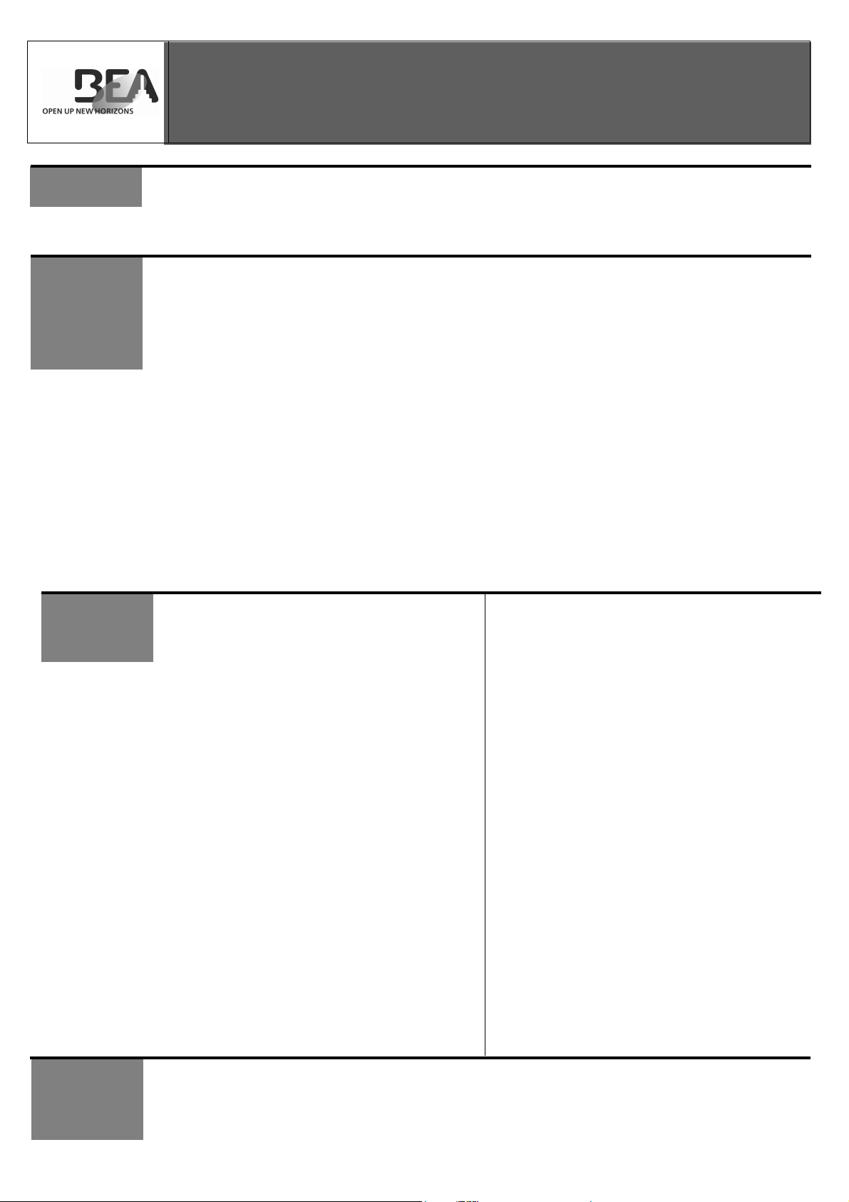
Functional wiring structure:
5 wires
Controller
Receiving module
Emitting module
Communication
16 times
Emitters
Receiving module
Emitting module
16 times
Emitters
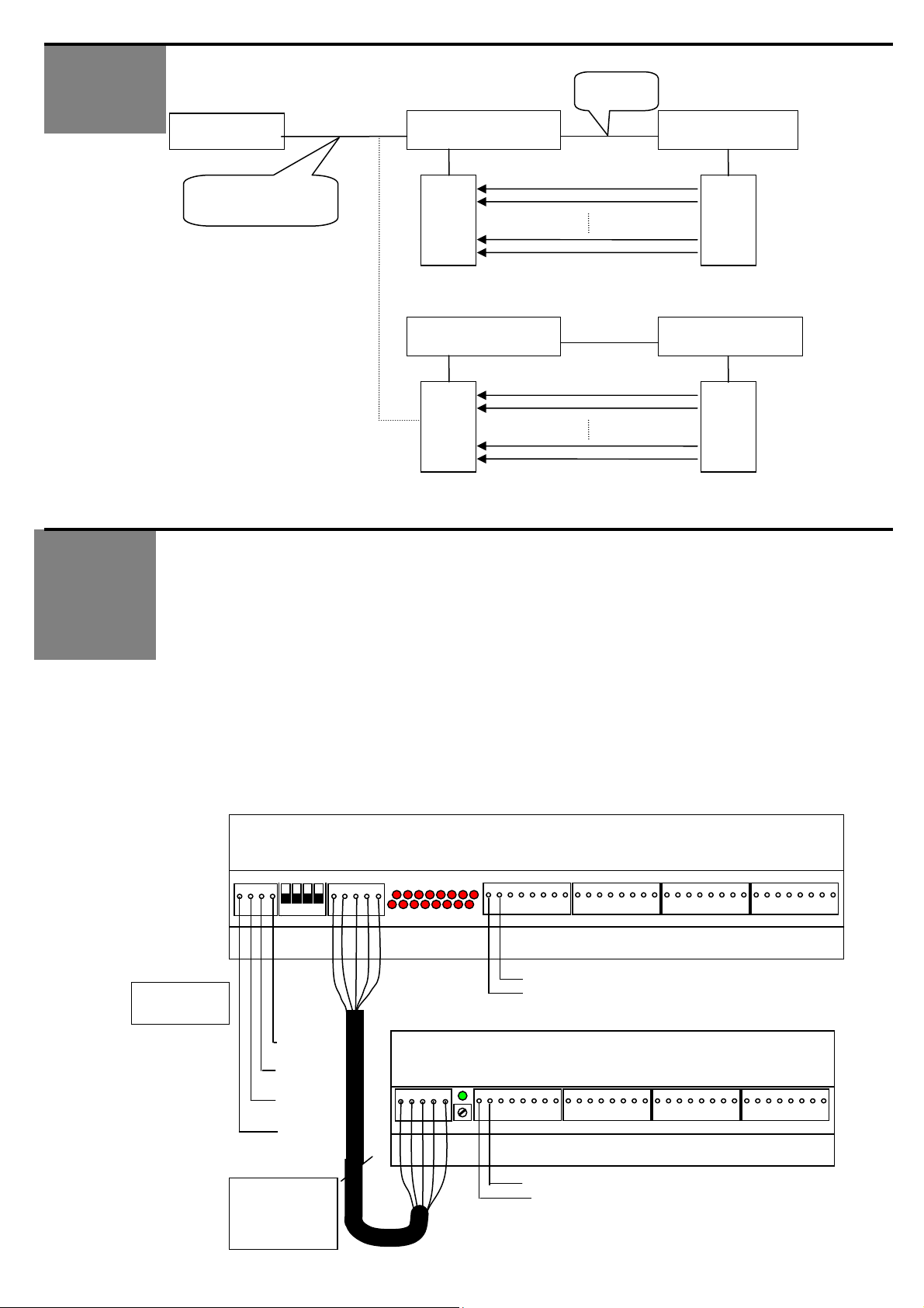
On the receiving module 16 red LEDs show the status of each beam. Plug connectors with 3.5 mm
pitch are used. The 2 twisted wires enable the connection of each head to the controller. The wires
must be between 0.5 m and 5 m long. Thanks to the multiplexing of the heads, there is no interference
between two heads.
The status information of the beams are transmitted to the controller via a RS485 communication. It is
possible to connect other terminals (maximum 32) on this bus.
The 2 modules composing the system are housed in aluminum profiles that can be fixed with screws or
with double-side adhesive.
A green LED on the emitting module indicates if the module is on. If the link between the 2 modules is
not correct, the LED will remain off and the MULTIBEAM will not work properly.
A potentiometer on the emitting module allows to adjust them emission power in order to reduce the
influence of one module to an other module in close proximity (turn clockwise = increase emission
power).
The receiver has a green cable and the emitter a yellow cable.
Wiring Diagram:
receiving and communication module
P1 SW1 P2 LEDS 16 Receiver head connectors
4 wires cable
to controller
Emitting module
P2 Potentiometer 16 emitter head conectors
First receiver head wiring
5 wires cable
between the 2
modules
Lmax = 5m
First emitter head wiring
Page 3

COMMUNICA –
TION STUCTURE
1. Hardware :
The communication module uses the standard RS485, the driver is a low EMI 250 Kbits-type,
protected against electrostatic discharges.
Up to 32 terminals may be connected on the same BUS line.
The twin-wire communication enables the Half Duplex operating mode.
A dip-switch enables you to choose the operating mode of the MULTIBEAM. Be aware to always
make an “on/off” operation on the MULTIBEAM after each modification to the dip-switches in order to
activate this modification.
SW mode
rate)
SW3 et SW4
(address)
OFF ASCII bus mode
ON quick mode
(House)
OFF 9600bps SW2 (baud
ON 19200bps
OFF,OFF address 0
OFF,ON address 1
ON,OFF address 2
ON,ON address 3
2. Software :
Dip switches enable you to choose between bus or quick mode.
With the dip-switch you can choose the baud-rate : 9600 or 19200 Bps.
2.1. ASCII BUS mode
The communication and the processing of head signals are asynchronous. The controller leads the
communication and sequentially questions the terminals on the BUS.
Each terminal has a different address. This address can be fixed between 0 and 3 thanks to the two
dip-switches, which can be found on the MULTIBEAM receiving module. The controller interrogation
speed can vary from 33ms to endless time without troubling the process of the module.
In case of communication interruption, the beams keep on working as well as the visualization LEDs.
A delay of 1,5 ms before the MULTIBEAM sends its answer has been added in order to avoid any
trouble on the RS485 line.
Structure of the byte for the ASCII BUS mode
Start bit, 7 data bits, 1 bit of even parity
and 1 stop bit.
Structure of the controller frame to the MULTIBEAM
Header ‘ :’
Address from 0 to 3 (for example '0' '1')
Function ‘0’ ‘0’
Checksum ‘F’ ‘F’ 2's complement (adress + function)
CRLF carriage return et linefeed 0x0d 0x0a
Total : 9 bytes
Structure of the MULTIBEAM frame to the controller
Header ‘ :’
Address from 0 to 3 (for example '0' '1')
Function ‘0’ ‘0’
low detection ’0’ ‘0’ (first 8 beams)
high detection ’0’ ‘0’ (last 8 beams)
Checksum ‘F’ ‘F’ 2's complement (address + function + low detection + high detection)
CRLF carriage return et linefeed 0x0d 0x0a
Total : 13 bytes
The response will be sent 1.5 ms after receiving the demand.
Page 4

COMMUNICA –
TION STUCTURE
Calculating the time of a cycle
Beams process time : 20.000ms
Transfer time of the frame to the MB at 9600 bps : 9.75ms
Waiting time between interrogation and answer : 1.50ms
Transfer time of the answer from the MB at 9600 bps : 13.54ms
Total time of a 9600 bps cycle : 44.8 ms
Beams process time : 20.000ms
Transfer time of the frame to the MB at 19200 bps : 4.69ms
Waiting time between interrogation and answer : 1.50ms
Transfer time of the answer from the MB at 19200 bps : 6.77ms
Total time of a 19200 bps cycle : 33 ms
2.2. Quick mode
It is a lightened communication mode adapted to a high speed use of the MULTIBEAM. The
configuration of this mode is the same as for the BUS mode, except that the controller interrogation
speed can vary from 26 ms to endless time without troubling the process of the module.
Byte structure for the quick mode Hexa:
start bit, 8 data bits and 1 stop bit, no parity.
Structure of the door controller frame to the MULTIBEAM
STX header value 2
Address of the interrogated control box of 00H, 01H, 02H or 03H (depends of the position of the dipswitches)
Checksum (STX + address) AND 127
ETX End of frame value 3
Total : 4 bytes
Structure of the MULTIBEAM frame to the door controller
STX header value 2
Module Address of 00H, 01H, 02H or 03H (depends on the position of the dip-switches)
Byte1 8 bits that match with the first 8 beams (Bit on 1 = detection)
Byte2 8 bits that match with the last 8 beams (Bit on 1 = detection)
Checksum (STX + Address + Byte1 + Byte2) AND 127
ETX End of frame value 3
Total : 6 bytes
The MSB of the checksum is on 1 if one of the receiving heads is shortcut. This function is not
available on BUS mode.
The working rhythm of the beams is independent of the communication.
Calculating the time of a cycle:
Beams process time : 20.000ms
Transfer time of the frame to the MB at 9600 bps : 4.17ms
Waiting time between interrogation and answer : 1ms
Transfer time of the answer from the MB at 9600 bps : 6.25ms
Total time of a 9600 bps cycle : 31.42ms
Beams process time : 20.0ms
Transfer time of the frame to the MB at 19200 bps : 2.09ms
Waiting time between interrogation and answer : 1ms
Transfer time of the answer from the MB at 19200 bps: 3.125ms
42.0567 / V1 – 01/07
Total time of a 19200 bps cycle : 26.215 ms
BEA S.A. - LIEGE Science Park – Allée des Noisetiers 5 – B-4031 Angleur - Tel: +3243616565 – Fax: +3243612858 – info@bea.be - www.bea.be
 Loading...