

Page 1
BOLLARD MOUNTING POST
USER’S GUIDE
MOUNTING POST FOR PUSHPLATES
1 Description
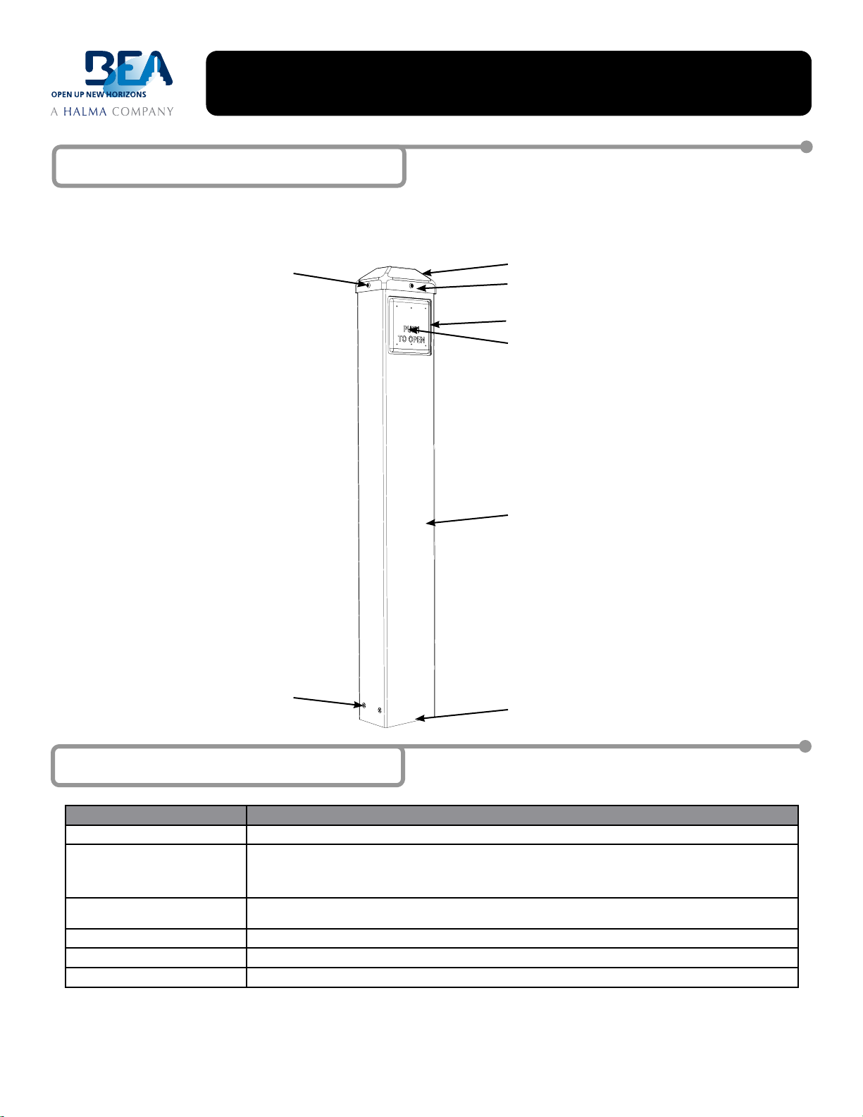
The Bollard (Black-10BOLLARDBLK, Bronze-10BOLLARDBRZ & Silver-10BOLLARDSLV) is used for mounting pushplates that activate automatic
doors. It will accept BEA’s 4 ½” Square Pushplate, 4 ¾” Square Pushplate, 4 ¾” Panther Pushplate, Dual Vestibule Pushplate and 4 ½” Round
Pushplate. The post is made of durable carbon steel and the mounting bracket is made of stainless steel for strength. It can be mounted on either
existing concrete or newly poured concrete.
CAP MOUNTING SCREWS (3)
PLASTIC CAP
TRANSMITTER MOUNTING TRAY (HIDDEN)
NOT USED WITH PANTHER APPLICATION
PUSHPLATE MOUNTING BOX (HIDDEN)
PUSHPLATE (NOT INCLUDED)
WILL ACCEPT:
4 1/2” SQUARE PUSHPLATE
(10PBS45X)
4 3/4” SQUARE PUSHPLATE
(10PBS, 10PBS1, 10PBS10)
4 3/4” SQUARE PANTHER PUSHPLATE
(10EMSQ475X)
DUAL VESTIBULE PUSHPLATE
(10PBDGP1)
4 1/2” ROUND PUSHPLATE
(10PBR45X)
POST ASSEMBLY
POST MOUNTING SCREWS (4)
POST MOUNTING BRACKET (HIDDEN)
2 Specications
DESCRIPTION SPECIFICATION
Dimensions (with cap attached) 41 ½”H x 6 ¼” W x 4 ¼”D
Material
• Post
• Cap
• Mounting Bracket
Pushplate Options 4 ½” Square Pushplate, 4 ¾” Square Pushplate, 4 ¾” Square Panther Pushplate, Dual Vestibule Pushplate
Weight 35 lbs (16 kilos)
Color Black, Bronze, Silver
Mounting Hardware L-anchor, Expansion Anchor, Split Washer and Nut (Included)
75.0131.05 20080606 Page 1 of 4
Powder-Coated (Inside and Out) Carbon Steel
UV-Resistant ABS Plastic
Stainless Steel
and 4 ½” Round Pushplate
Page 2
3 Precautions
2.19 in
55.58 mm
1/4-20
53.95 mm
2.12 in
3.65 in
25.40 mm
143.51 mm
5.65 in
0.44 in
11.11 mm
92.71 mm
1.00 in
39.37 mm
1.55 in
3.55 in
92.10 mm
Shut off all power before attempting any wiring procedures.
Maintain a clean & safe environment when working in public areas.
Constantly be aware of pedestrian trafc around the door area.
Always stop pedestrian trafc through the doorway when performing tests that may result in unexpected reactions by the door.
Always check placement of all wiring before powering up to insure moving door parts will not catch any wires and cause
damage to equipment.
Ensure compliance with all applicable safety standards (i.e. ANSI A156.19 / A156.10) upon completion of installation.
DO NOT attempt any internal repair of the sensor. All repairs and/or component replacements must be performed by BEA, Inc.
Unauthorized disassembly or repair:
1. May jeopardize personal safety and may expose one to the risk of electrical shock.
2. May adversely affect the safe and reliable performance of the product resulting in a voided warranty.
4 Pre Installation Check
1. When preparing to wire multiple devices together for a ‘system’ conguration, it is best to ensure the correct operation of each device
independently before starting to help reduce troubleshooting time later in the event of a discrepancy.
2. Prior to installing any equipment, ensure correct line voltage and stability. When applying equipment on a new installation utilizing new
electrical supply circuits, always ensure correct line voltage exists and is stable. Remember to shut the power back off after this is checked
and before performing any wiring to the system.
5 Installation
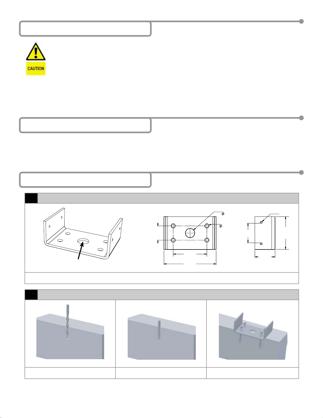
Hardwire Bracket - Optional
1
FOR HARDWIRING RUN WIRE
THROUGH 1” DIAMETER HOLE
1. The Bollard is designed to house a pushplate used to activate a door by either a remote controlled transmitter or hardwired directly to the
door control. If the door is hardwired, pass the wire through the 1 inch diameter hole in the mounting bracket.
Attach Mounting Bracket Using Expansion Anchors - Existing Concrete
2
1. Mark and drill 3/8” diameter hole in four
locations.
Page 2 of 4 75.0131.05 20080606
2. Hammer in and set anchor in four hole
locations.
3. Install and tighten nuts to secure mounting
bracket.
Page 3

5 Installation (Continued)
Attach Mounting Bracket Using ‘L’ Shaped Anchors - New Concrete
3
1” EXPOSED
6”
1. Pour concrete at least 6 inches deep. 2. Insert anchors into curing concrete. Leave
Attach Post to Mounting Bracket
4
1. Align post to mounting bracket and attach post to mounting bracket with four post mounting screws.
Install Pushplate
5
at least 1 inch exposed.
3. Once concrete has cured attach anchor and
tighten nuts onto mounting bracket.
PUSHPLATE INSTALLATION DUAL PUSHPLATE INSTALLATION PANTHER PUSHPLATE INSTALLATION
1. Thread the pushplate screws into the mounting box leaving a majority of the screw exposed. Attach the pushplate to the mounting screws,
then use the hex key provided to fully tighten the screws. Refer to the appropriate Pushplate User’s Guide for detailed installation and setup
instructions.
75.0131.05 20080606 Page 3 of 4
Page 4

5 Installation (Continued)
Attach Transmitter
6
TRANSMITTER MOUNTING TRAY
ATTACH TO PUSHPLATE
NOTE: PANTHER PUSHPLATES DO NOT
REQUIRE A TRANSMITTER.
ATTACH
TRANSMITTER
HERE
CAUTION: IF THE TRANSMITTER IS ALLOWED TO HANG DOWN INSIDE THE BOLLARD, ERRATIC OPERATION MAY OCCUR.
1. If using the transmitter for this application, attach transmitter to mounting tray with velcro pad included in the package. Hardwired systems do
not require this step.
2. Attach plastic cap to top of the post with three cap mounting screws. Tighten screws with hex key included in the pushplate package.
6 Company Contact
Do not leave problems unresolved. If a satisfactory solution cannot be achieved after troubleshooting a problem, please
call BEA, Inc. If you must wait for the following workday to call BEA, leave the door inoperable until satisfactory repairs
can be made. Never sacrice the safe operation of the automatic door or gate for an incomplete solution.
The following numbers can be called 24 hours a day, 7 days a week. For more information visit www.beasensors.com.
West:
South-East:
US and Canada:
1-888-419-2564
1-800-407-4545
1-866-249-7937
Mid-West:
North-East:
Canada:
1-888-308-8843
1-866-836-1863
1-866-836-1863
Page 4 of 4 75.0131.05 20080606
 Loading...