

BE I2000L Operation Manual
INVERTER
GENERATOR
I2000L
Operation Manual

TABLE OF CONTENTS TABLE OF CONTENTS
Safety
4 Introduction
5 Safety Warnings
6 Safety Information
Description
10 Description
11 Control Panel
Control Function
12 3 in 1 switch knob
12 Oil warning light (red)
13 Overload indicator light (red)
13 AC pilot light (green)
14 DC protector
14 Engine smart control (ESC)
15 Fuel tank cap
15 Fuel tank cap air vent knob
15 Ground (Earth) terminal
Preparation
16 Fuel
16 Engine oil
17 Pre-operation check
Operation
18 Operation
19 Staring the engine
20 Stopping the engine
21 Alternating Current (AC) connection
21 Battery Charging
23 Application range
Maintenance
25 Maintenance
27 Spark plug inspection
28 Carburetor adjustment
28 Engine oil replacement
29 Air filter
30 Muffler screen and spark Arrester
31 Fuel tank filter
31 Fuel filter
Storage
32 Drain the fuel
32 Engine
Troubleshooting
32 Engine won’t start
34 Generator won’t produce power
34 Specifications
35 Wiring Diagram
Parallel Function
36 Parallel function instructions
2
3
INTRODUCTION SAFETY
Attention: Read through the complete manual
prior to the initial use of your generator.
Using the Operator’s manual
The operating manual is an important part of your generator. It should
be read thoroughly before initial use, and referred to often to make sure
adequate safety and service concerns are being addressed.
Reading the owner’s manual thoroughly will help avoid any personal injury
or damage to your machine. By knowing how best to operate this
machine you will be better positioned to show others who may also
operate the unit.
This manual contains information for the complete range of BE
generators, and was written to take you from the safety requirements
to the operating functions of your machine. You can refer back to the
manual at any time to help troubleshoot any specific operating functions,
so store it with the machine at all times.
Save these Instructions
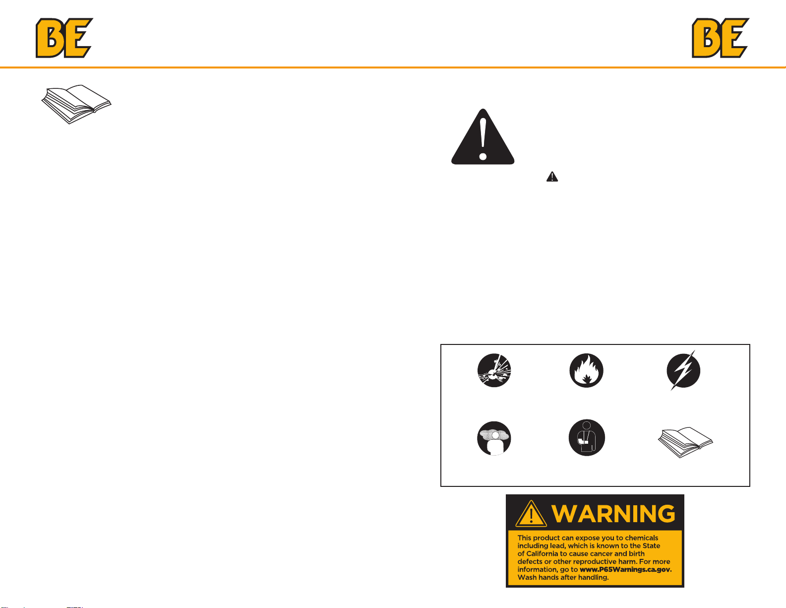
Safety Warnings
This is the safety alert symbol. It is used to alert
you to potential personal injury hazards. Obey
all safety messages that follow this symbol to
avoid possible injury or death.
The safety alert symbol ( ) is used with a signal word (DANGER,
CAUTION, WARNING), a pictorial and/or a safety message to alert
you to hazards.
DANGER you WILL be KILLED or SERIOUSLY HURT if you don’t
follow instructions.
WARNING you CAN be KILLED or SERIOUSLY HURT if you don’t
follow instructions.
CAUTION you CAN be HURT if you don’t follow instructions
NOTICE your generator or other property could be damaged if you
don’t follow instructions.
Hazard Symbols and Meanings
explosion
toxic fumes
4
fire electric shock
kickback read manual
5
SAFETY SAFETY
1. SAFETY INFORMATION
Read and understand this owner’s manual before operating your
generator. It will help you avoid accidents if you get familiar with your
generator’s safe operation procedures.
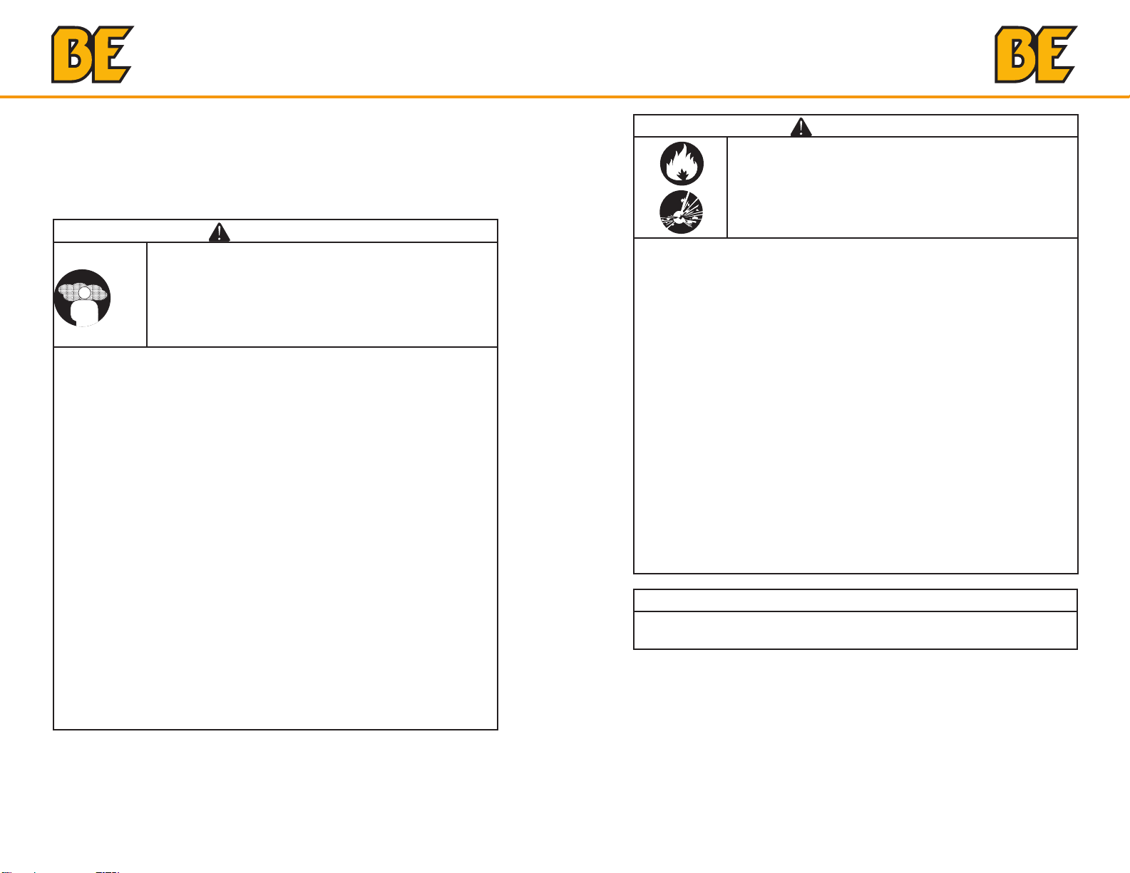
WARNING
Generator exhaust contains carbon monoxide, a
poisonous gas that can kill you.
You CANNOT smell or see this gas.
• Use the generator outdoors, away from open windows, vents, or
doors that could allow the carbon monoxide gas to come indoors.
Keep the generator at least 1 meter (3 feet) away from any structure
or building during use.
• NEVER use a generator indoors, including in homes, garages,
basements, crawl spaces, and other enclosed or partially-enclosed
areas, even with ventilation. Opening doors and windows or using
fans will not prevent carbon monoxide build-up in the home.
• NEVER use a generator in enclosed or partially-enclosed spaces.
Generators can produce high levels of carbon monoxide very quickly.
When you use a portable generator, remember that you cannot smell
or see carbon monoxide. Even if you can’t smell exhaust fumes, you
may still be exposed to carbon monoxide.
• NEVER operate the generator in an explosive atmosphere, near
combustible materials or where ventilation is not sufficient to carry
away exhaust fumes. Exhaust fumes can cause serious injury or death.
• If you start to feel sick, dizzy, or weak while using a generator, get
to fresh air RIGHT AWAY. DO NOT DELAY. The carbon monoxide
from generators can rapidly lead to full incapacitation and death.
• If you experience serious symptoms, get medical attention
immediately. Inform medical staff that carbon monoxide poisoning
is suspected. If you experienced symptoms while indoors, have
someone call the fire department to determine when it is safe to
re-enter the building.
WARNING
Fuel and its vapors are extremely flammable and
explosive.
Fire or explosion can cause severe burns or death.
When Adding or Draining Fuel
• Observe all safety regulations for the safe handling of fuel. Handle
fuel in safety containers. If the container does not have a spout, use
a funnel.
• Do not overfill the fuel tank, leave room for the fuel to expand.
• Do not refill fuel tank while the engine is running. Before refueling the
generator, turn it off and let it cool down. Gasoline spilled on hot
engine parts could ignite.
• Fill the tank only on an area of bare ground. While fueling the tank,
keep heat, sparks and open flame away. Carefully clean up any spilled
fuel before starting engine.
• Always fill fuel tank in an area with plenty of ventilation to avoid
inhaling dangerous fumes.
• NEVER store fuel for your generator in the home. Gasoline, propane,
kerosene, and other flammable liquids should be stored outside of
living areas in properly-labeled, non-glass safety containers. Do not
store them near a fuel-burning appliance, such as a natural gas water
heater in a garage. If the fuel is spilled or the container is not sealed
properly, invisible vapors from the fuel can travel along the ground and
can be ignited by the appliance’s pilot light or by arcing from electric
switches in the appliance.
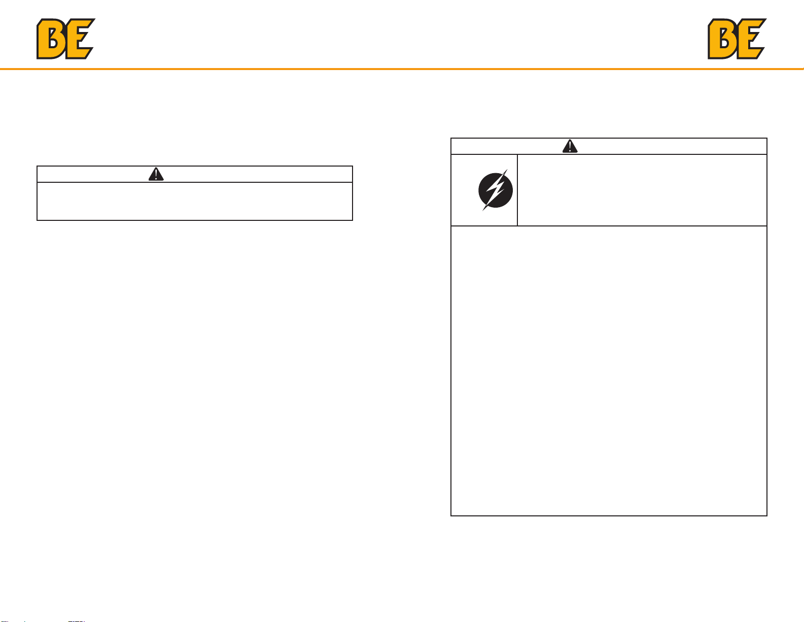
WARNING
THERE IS A PERMANENT CONDUCTOR BETWEEN THE
GENERATOR (STATOR WINDING) AND THE FRAME.
6
7
SAFETY SAFETY
Ground Fault Circuit Interrupter Protection
These generators are equipped with a GFCI (Ground Fault Circuit
Interrupters) 120V duplex receptacles for protection against the hazards
of electrical shock from defective attachments such as tools, cords,
and cables.
WARNING
• The GFCI may not function unless the generator is properly
grounded. Follow the correct procedure specified in the section
labeled GROUNDING INSTRUCTIONS.
A GFCI is a device that interrupts electricity from either the utility or
generator by means of a special type of circuit breaker that determines if
a current flow to the ground occurs.
A GFCI can be used only with generators that have the neutral wire
internally bonded to the frame, and the frame properly grounded to the
earth. A GFCI will not work on generators that do not have the neutral
wire bonded to the frame, or on generators which have not been properly
grounded. All BE generators have internally bonded ground wires.
This product has been designed with internal grounding or floating
bonded neutral. If it should malfunction or breakdown, grounding
provides a path of least resistance for electric current to reduce the risk
of electric shock.
DANGER
Improper grounding can result in a risk of electrocution.
Check with a qualified electrician for your local
requirements if you are in doubt as to whether the unit
is properly grounded.
• This generator is equipped with a grounding terminal for added
protection. Using the ground path from the generator to an external
ground source as instructed in the section labeled “Grounding
Instructions” in the Preparation section of this manual can be
necessary. Please consult a qualified electrician for local regulations.
• The generator is a potential source of electrical shock if not kept dry.
Keep the generator dry and do not use in rain or wet conditions. To
protect from moisture, operate it on a dry surface under an open,
canopy-like structure. Dry your hands if wet before touching the
generator.
• Plug appliances directly into the generator. Or, use a heavy duty,
outdoor-rated extension cord that is rated (in watts or amps) at least
equal to the sum of the connected appliance loads. Check that the
entire cord is free of cuts or tears and that the plug has all three
prongs,especially a grounding pin.
• NEVER try to power the house wiring by plugging the generator into
a wall outlet, a practice known as “back feeding”. This is an extremely
dangerous practice that presents an electrocution risk to utility
workers and neighbors served by the same utility transformer. It also
bypasses some of the built-in household circuit protection devices.
• If you must connect the generator to the house wiring to power
appliances, have a qualified electrician install the appropriate
equipment in accordance with local electrical codes.
8
9
DESCRIPTION DESCRIPTION
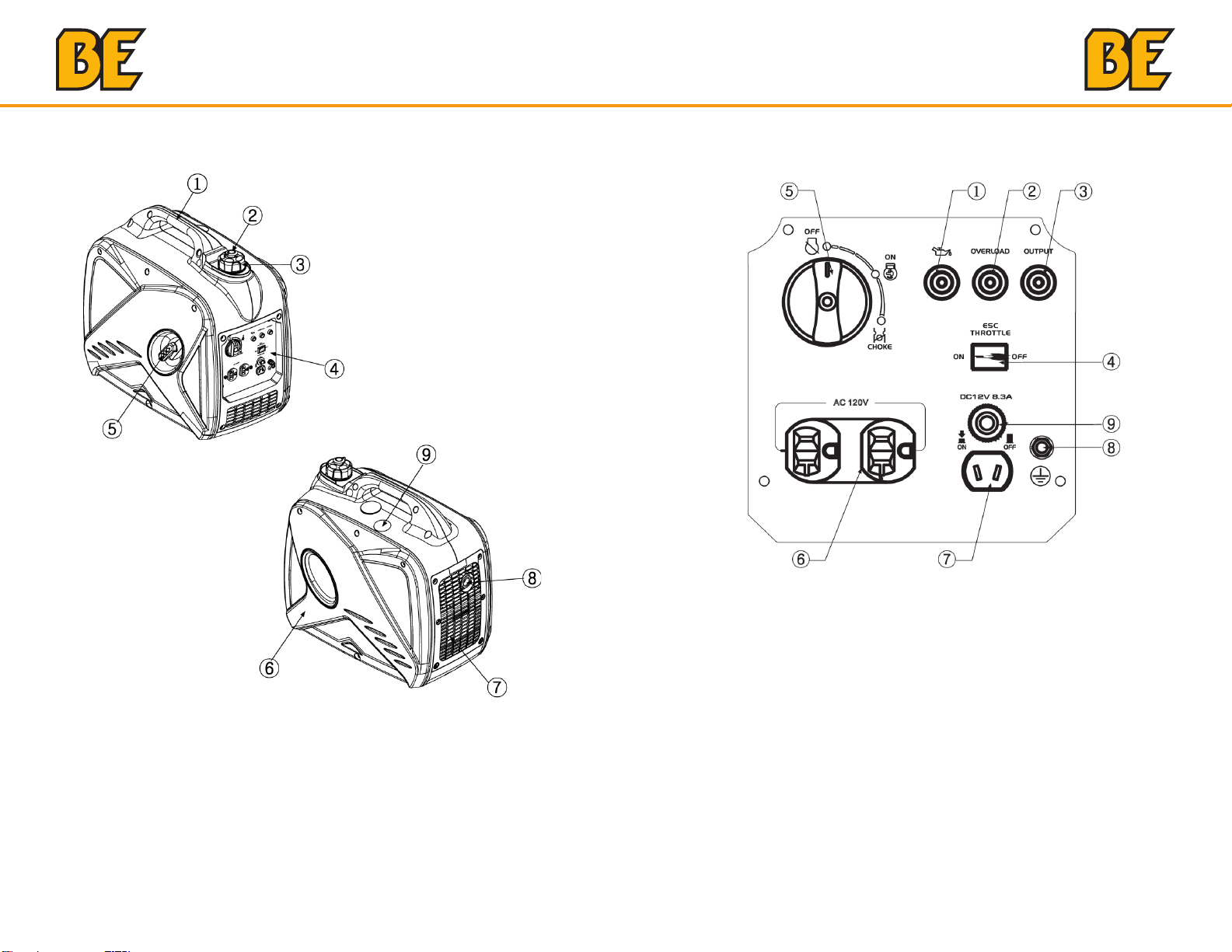
3. DESCRIPTION
3.1 Control Panel
1. Carrying handle
2. Fuel tank cap air vent knob
3. Fuel tank cap
4. Control panel
5. Recoil starter
6. Oil filler cap
7. Louver
8. Muffler
9. Spark plug maintenance cover
10
1. Oil warning light
2. Overload indicator light
3. AC pilot light
4. ESC (Engine Smart Control)
5. 3 in 1 switch knob (including start/stop switch, fuel valve and choke)
6. AC receptacle
7. DC receptacle
8. Ground (earth) terminal
9. DC protector
11
CONTROL FUNCTION CONTROL FUNCTION
4. CONTROL FUNCTION
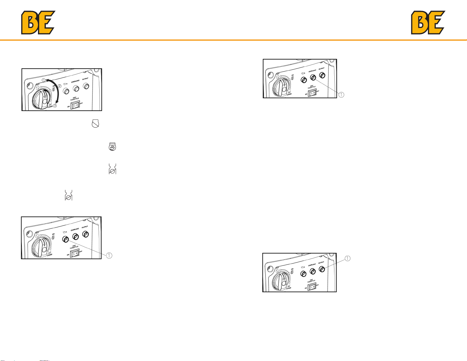
4.1 3 in 1 switch knob
(1) Engine switch\fuel valve “OFF”;
Ignition circuit is switched off. Fuel is switched off.
The engine will not run.
(2) Engine switch\fuel valve\choke “ON”;
Ignition circuit is switched on. Fuel is switched on. Choke is switched
on. The engine can be running.
(3) Engine switch\fuel valve\choke “CHOKE”;
Ignition circuit is switched on. Fuel is switched on. Choke is switched
off. The engine can be started.
TIP: The choke “ ” is not required to start a warm engine.
4.2 Oil warning light (red)
4.3 Overload indicator light (red)
The overload indicator light (1) comes on when an overload of a
connected electrical device is detected, the inverter control unit
overheats, or the AC output voltage rises. Then, the AC protector will
trip, stopping power generation in order to protect the generator and any
connected electric devices. The AC pilot light (Green) will go off and the
overload indicator light (Red) will stay on, but the engine will not stop
running.
When the overload indicator light comes on and power generation stops,
proceed as follows:
1. Turn off any connected electric devices and stop the engine.
2. Reduce the total wattage of connected electric devices within the
rated output.
3. Check for blockages in the cooling air inlet and around the control
unit. If any blockages are found, remove.
4. After checking, restart the engine.
TIP: The overload indicator light may come on for a few seconds at first
when using electric devices that require a large starting current, such as
a compressor or a submergible pump. However, this is not a malfunction.
When the oil level falls below the lower level, the oil warning light (1)
comes on and then the engine stops automatically. Unless you refill with
oil, the engine will not start again.
TIP: If the engine stalls or does not start, turn the engine switch to “ON”
and then pull the recoil starter. If the oil warning light flickers for a few
seconds, the engine oil is insufficient. Add oil and restart.
12
4.4 AC pilot light (green)
The AC pilot light (1) comes on when the engine starts and produces
power.
13
CONTROL FUNCTION CONTROL FUNCTION
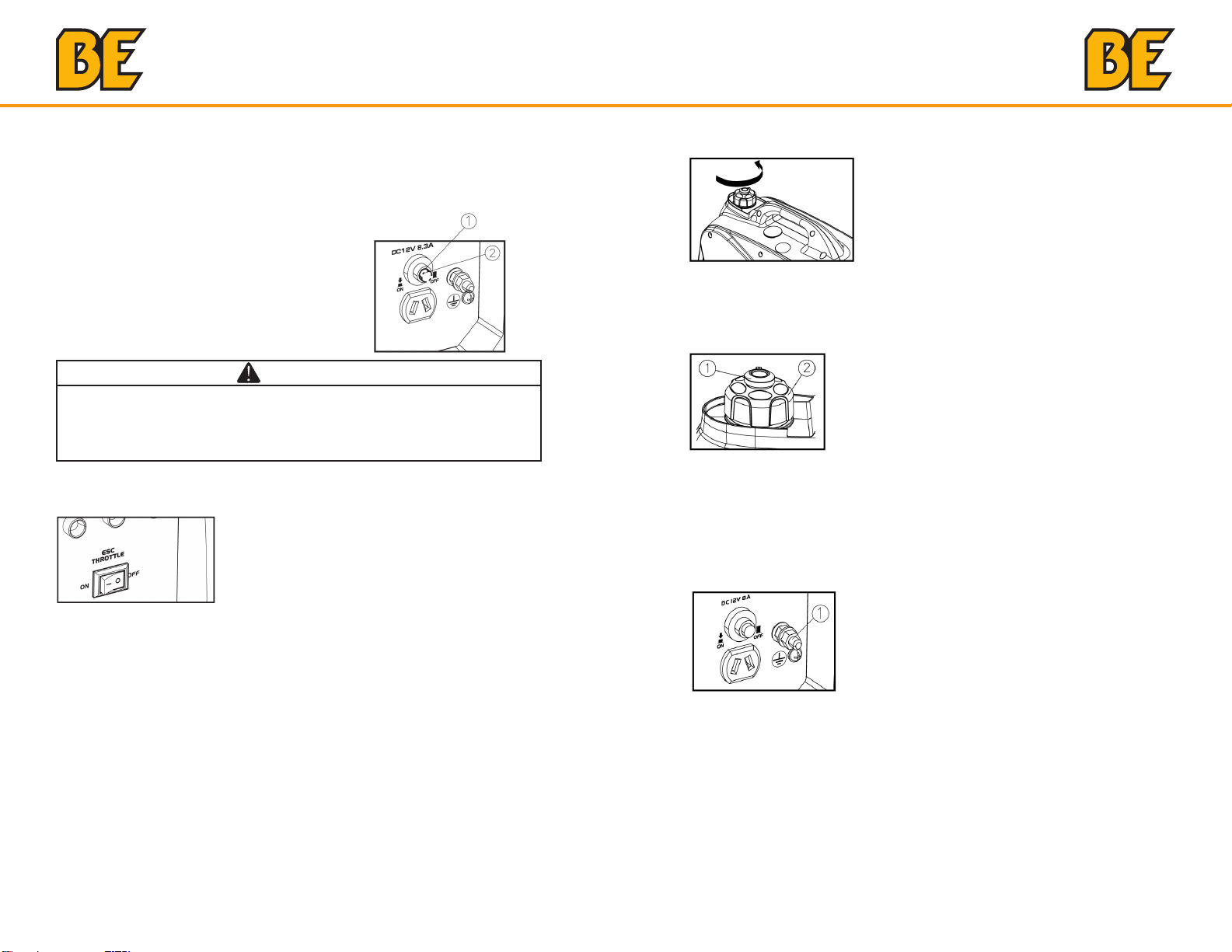
4.5 DC protector
The DC protector turns to “OFF” (2) automatically when electric device
being connected to the generator is operating and current above the
rated flows. To use this equipment again, turn on DC protector by
pressing its button to “ON” (1)
(1) “ON”
Direct current is output.
(2) “OFF”
Direct current is not output.
CAUTION
• Reduce the load of the connected electric device below the specified
rated output of the generator if the DC protector turns off. If the DC
protector turns off again, stop using the device immediately and
consult our company authorized dealer.
4.6 Engine smart control (ESC)
①
4.7 Fuel tank cap
Remove the fuel tank cap by turning it counterclockwise.
4.8 Fuel tank cap air vent knob
The fuel tank cap (2) is provided with an air vent knob to (1) stop fuel
flow. The air vent knob must be turned to “ON”. This will allow fuel to flow
to the carburetor and the engine to run. When the engine is not in use,
turn the air vent knob to “OFF” to stop fuel flow.
4.9 Ground (Earth) terminal
(1) “ON”
When the ESC switch is turned to “ON”, the economy control unit
controls the engine speed according to the connected load. The results
are better fuel consumption and less noise.
(2) “OFF”
When the ESC switch is turned to“OFF”, the engine runs at the rated
r/min(4500r/min) regard-less of whether is a load connected or not.
TIP: The ESC must be turned to“OFF”when using electric devices that
require a large starting current, such as a compressor of a submergible
pump.
14
Ground (Earth) terminal (1) connects the earth line for prevention of
electric shock. When the electric device is grounded, always the ground
the generator.
15
PREPARATION PREPARATION
5. PREPARATION
5.1 Fuel
DANGER
• Fuel is highly flammable and poisonous. Check
“SAFETY INFORMATION” carefully before filling.
• Do not overfill the fuel tank, otherwise it may
overflow when the fuel warms up and expands.
• After filling, make sure the fuel tank cap is
tightened securely.
NOTICE
• Immediately wipe off spilled fuel with a clean, dry, soft cloth, since fuel
may deteriorate painted surfaces or plastic parts.
• Use only unleaded gasoline. The use of leaded gasoline will cause
severe damage to internal engine parts.
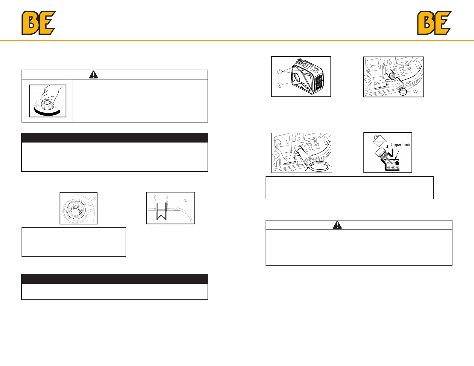
Remove the fuel tank cap and fill the fuel into the tank up to the red level.
(1) Red line (2) Fuel level
3. Remove the oil filler cap (3).
4. Fill the specified amount of the recommended engine oil, and then
install and tighten the oil filler cap.
5. Install the cover and tighten the screws.
Recommended engine oil: SAE SJ 15W-40
Recommended engine oil grade: API Service SE type or higher
Engine oil quantity: 0.35 L
5.3 Pre-Operation check
Recommended fuel:
Unleaded gasoline
Fuel tank capacity:
Total: 4.0L (1.06 US gal, 0.88 lmp gal)
5.2 Engine oil
NOTICE
• The generator has been shipped without engine oil. Do not start the
engine without filling with the sufficient engine oil.
1. Place the generator on a level surface.
2. Remove the screws (1), and then remove the cover (2).
16
WARNING
• If any item in the Pre-operation check is not working properly, have it
inspected and repaired before operating the generator.
• The condition of a generator is the owner’s responsibility. Vital
components can start to deteriorate quickly and unexpectedly, even if
the generator unused.
TIP: Pre-operation checks should be made each time the generator is
used.
Pre-operation check
Fuel (See page 16)
• Check fuel level in fuel tank.
• Refuel if necessary.
Engine oil (See page 17)
• Check oil level in engine.
• If necessary, add recommended oil to specified level.
• Check generator for oil leakage.
17
PREPARATION OPERATION
6. OPERATION
WARNING
• Never operate the engine in a closed area or it may cause
unconsciousness and death within a short time. Operate the engine
in a well ventilated area.
• Before starting the engine, do not connect any electric devices.
NOTICE
• The generator has been shipped without engine oil. Do not start the
engine till fill with the sufficient engine oil.
• Do not tilt the generator when adding engine oil. This could result in
overfilling and damage to the engine.
TIP: The generator can be used with the rated output load at standard
atmospheric conditions.
“Standard atmospheric conditions”
Ambient temperature 25°
Barometric pressure 100kPa
Relative humidity 30%
The output of the generator varies due to change temperature, altitude
(lower air pressure at higher altitude) and humidity.
The output of the generator is reduced when the temperature, the
humidity and the altitude are higher than standard atmospheric
conditions.
Additionally, the load must be reduced when using in a confined area, as
generator cooling is affected.
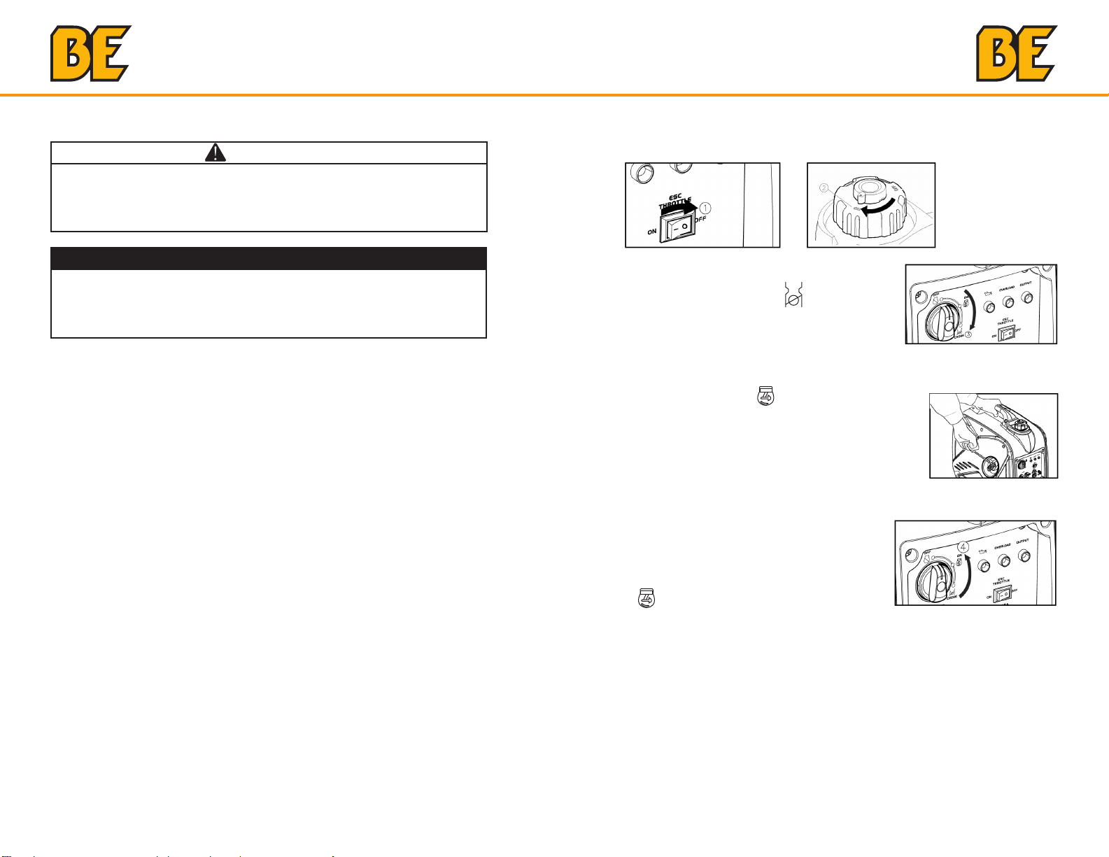
6.1 Starting the engine
1. Turn the ESC switch to “OFF” (1).
2. Turn the air vent knob to “ON” (2).
3. Turn the 3 in 1 switch to “CHOKE” (3),
a. Ignition circuit is switched on.
b. Fuel is switched on.
c. Choke is switched off
TIP: The choke is not required to start a warm engine. Push the choke
knob in to the position “ON”.
4. Pull slowly on the recoil starter until
it is engaged, then pull it briskly.
TIP: Grasp the carrying handle firmly to prevent the generator from falling
over when pulling the recoil starter.
5. After the engine starts, warm up the
engine until the engine does not stop
when the choke knob is returned to the
“ON” position (4).
18
TIP: When starting the engine, with the ESC “ON”, and there is no load
on the generator:
• In ambient temperature below 0°C (32°F), the engine will run at the
rated r/min (4500r/min) for 5 minutes to warm up the engine.
• In ambient temperature below 5°C (41°F), the engine will run at the
rated r/min (4500r/min) for 3 minutes to warm up the engine.
• The ESC unit operates normally after the above time period, while the
ESC is “ON”.
19

OPERATION OPERATION
6.2 Stopping the engine
TIP: Turn off any electric devices.
1. Turn the ESC to “OFF” (1).
2. Disconnect any electric devices.
3. Turn the 3 in 1 switch to “OFF” (2),
a. Ignition circuit is switched off.
b. Fuel is switched off.
6.3 Alternating Current (AC) connection
WARNING
• Be sure any electric devices are turned off before plugging them in.
NOTICE
• Be sure all electric devices including the lines and plug connections
are in good condition before connection to the generator.
• Be sure the total load is within generator rated output.
• Be sure the receptacle load current is within receptacle rated current.
• The generator (STATOR WINDING) is isolated from the AC receptacle ground pin.
• Electrical devices that require a grounded receptacle pin connection
will not function if the receptacle ground pin is not functional.
TIP: Make sure to ground (Earth) the generator. When the electrical
device is grounded, the generator must also be grounded.
1. Start the engine.
2. Turn the ESC to “ON”.
3. Plug in to AC receptacle.
4. Make sure the AC pilot light is on.
5. Turn on any electric devices.
TIP: The ESC must be turned to “OFF” to increase engine speed to
rated rpm. If the generator is connected to multiple loads or electricity
consumers, please remember to first connect the one with the highest
starting current and last connect the one with the lowest starting current.
4. Turn the fuel tank cap air vent knob to “OFF” (3) after the engine has
completely cooled down.
20
6.4 Battery Charging
TIP:
• The generator DC rated voltage is 12V.
• Start the engine first, and then connect the generator to the battery for
charging.
• Before starting to charge the battery, make sure that the DC protector is
turned on.
1. Start the engine.
2. Connect the red battery charger lead to the positive (+) battery
terminal.
3. Connect the black battery charger lead to the negative (-) battery
terminal.
4. Turn the ESC “off” to start battery charging.
21
OPERATION OPERATION
NOTICE
• Be sure the ESC is turned off while charging the battery.
• Be sure to connect the red battery charger lead to the positive (+)
battery terminal ,and connect the black lead to the negative (-) battery
terminal. Do not reverse these positions.
• Connect the battery charger leads to the battery terminals securely
so that they are not disconnected due to engine vibration or other
disturbances.
• Charge the battery in the correct procedure by following instructions
in the owner’s manual for the battery.
• The DC protector turns off automatically if current above the rated
flows during battery charging. To restart charging the battery, turn the
DC protector on by pressing its button to “ON”. If the DC protector
turns off again, top charge the battery immediately and consult our
company authorized dealer.
TIP:
• Follow instructions in the owner’s manual for the battery to determine
the end of battery charging.
• Measure the specific gravity of electrolyte to determine if the battery is
fully charged. At full charge, the electrolyte specific gravity is between
1.26 and 1.28.
• It is advisable to check the specific gravity of the electrolyte at least
once every hour to prevent overcharging the battery.
WARNING
• Never smoke or make and break connections at the battery while
charging. Sparks may ignite the battery gas.
• Battery electrolyte is poisonous and dangerous, causing severe
burns, etc. contains sulfuric (sulphuric) acid. Avoid contact with skin,
eyes or clothing.
• Antidote:
EXTERNAL: Flush with water.
INTERNAL: Drink large quantities of water or milk. Follow with milk of
magnesia, beaten egg or vegetable oil . Call physician immediately.
EYES: Flush with water for 15 minutes and get prompt medical
attention.
• Batteries produce explosive gases. Keep sparks, flame, cigarettes,
etc., away. Ventilate when charging or using in closed space. Always
cover eyes when working near batteries.
• Keep out of reach of children.
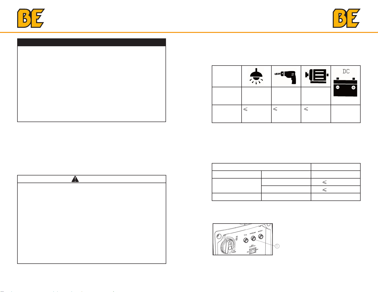
6.5 Application range
When using the generator, make sure the total load is within rated output
of a generator. Otherwise, generator damage may occur.
AC
Power
Factor
Rated
output
power
TIP:
• Application wattage indicates when each device is used by itself.
• The simultaneous usage of AC and DC power is possible but total
wattage should not exceed the rated output.
EX:
Frequency Power factor
The overload indicator (1) comes on when total wattage exceeds the
application range. (See page 11 for more details.)
1 0.8-0.95 0.4-0.75
(Efficiency
0.85)
1,600W 1,280W 544W Rated
voltage 12V
Generator rated output 1,600W
1.0 1,600W
AC
DC --- 96W (12V/8.3A)
0.8 1,280W
22
23
 Loading...