

Page 1
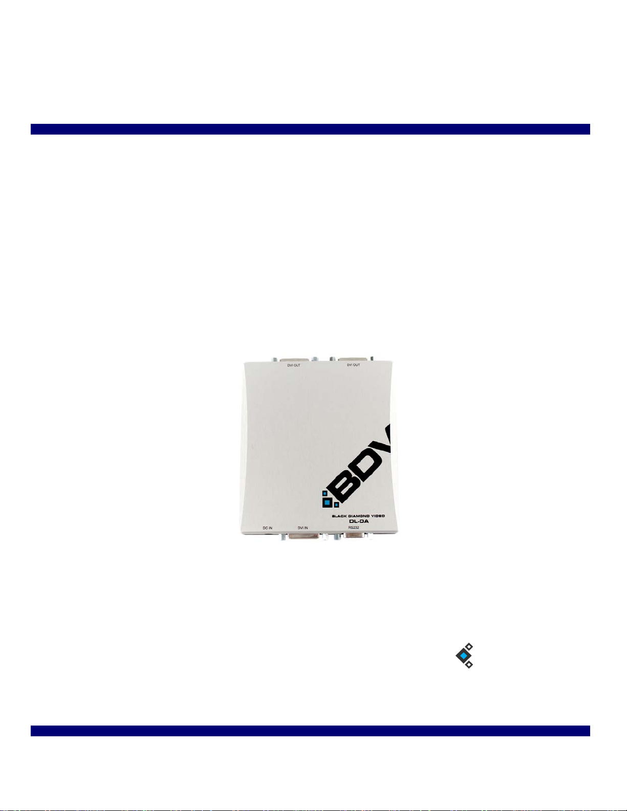
DVI DL-DA S plitter
BDV
BLACK DIAMOND VIDEO
Installation & Operation Guide
Edition 1.01
August 3, 2011
Page 2

Edition 1.01 DVI DL-DA Splitter: Installation & Operation Guide
Page 3

. . . . .
. . . . . . . . . . . . . . . . . . . . . . . . . . . . . . . . . . .
Contents
Chapter 1 Product Information 1
About the DVI DL-DA Splitter 1
Key Features & Specifications 1
Output Panel Detail 2
Video Input Detail 3
Customer Service and Support 4
Chapter 2 Installation Instructions 5
DVI DL-DA Splitter Installation 5
Establishing RS-232 Control 6
Appendix A RS-232 Protocol 7
DVI DL-DA Splitter Command Set 7
DVI DL-DA Splitter: Installation & Operation Guide Edition 1.01 Contents i
Page 4

ii Contents Edition 1.03 DVI DL-DA Splitter: Installation & Operation Guide
Page 5
. . . . .
. . . . . . . . . . . . . . . . . . . . . . . . . . . . . . . . . . .
P
. . . . . . . . . . . . . . . . . . . . . . . . . . . . . . . . . . . . . . . . . . . . . . . . . . . .
. . . . . . . . . . . . . . . . . . . . . . . . . . . . . . . . . . . . . . . . . . . . . . . . . . . .
RODUCT INFORMATION
ABOUT THE DVI DL-DA SPLITTER
Black Diamond Video’s compact DVI DL-DA Splitter provides single-link or dual-link
DVI distribution amplification. The DVI DL-DA Splitter can route DVI signals from one
signal source to up to two DVI display devices.
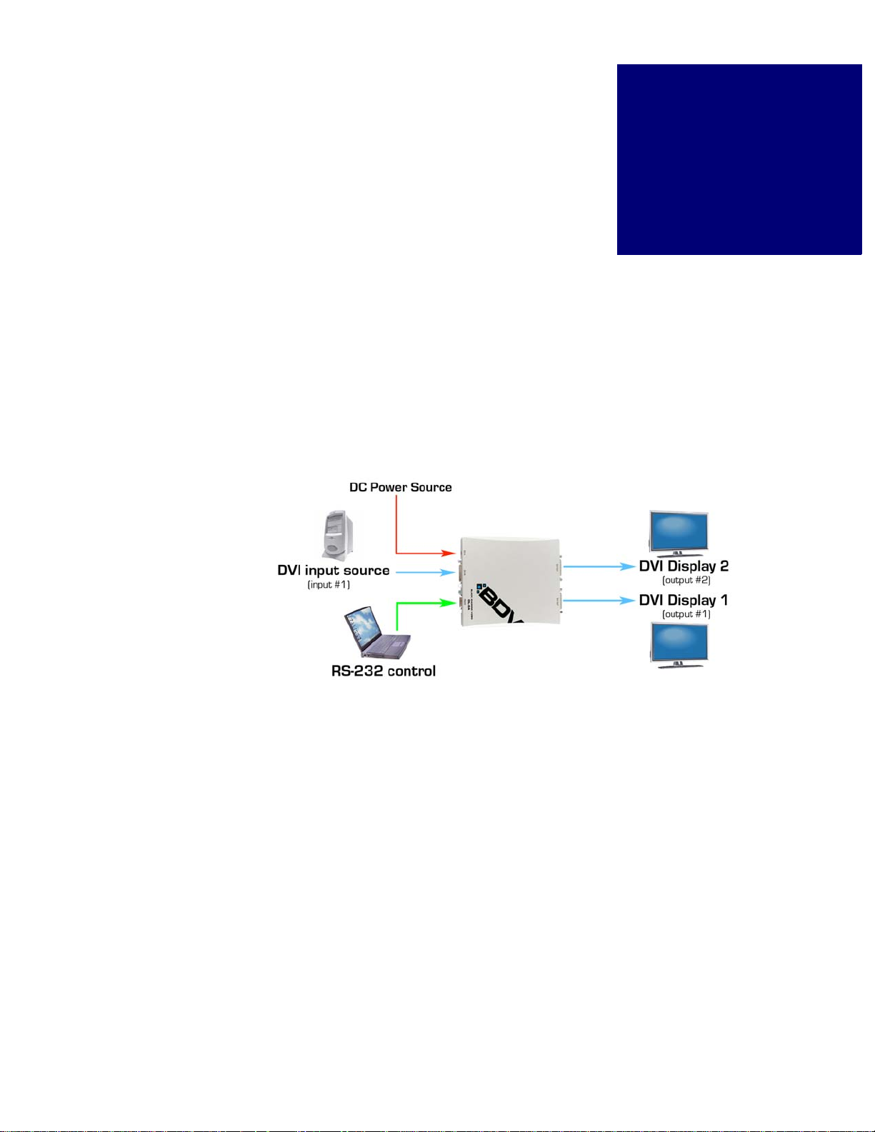
The system diagram (Figure 1) illustrates the simple installation of the DVI DL-DA
Splitter.
1
FIGURE 1. DVI DL-DA System Diagram
KEY FEATURES & SPECIFICATIONS
Features and specifications include the following:
VIDEO INPUT
• One DVI dual-link input, DVI 1.0.
VIDEO OUTPUT
• Two DVI dual-link outputs, DVI 1.0
MAXIMUM DATA RATE
• 3 Gbps.
DVI DL-DA Splitter: Installation & Operation Guide Edition 1.01 Introduction 1
Page 6
PRODUCT INFORMATION
. . . . . . . . . . . . . . . . . . . . . . . . . . . . . . . . . . . . . . . . . . . . . . . . . . . .
LQ PP
LQ
PP
LQ PP LQ PP
Output Panel Detail
DUAL LINK RANGE
• 3840 x 2400
CONTROL
• RS-232 serial control. Connector: RJ11. An R J11 to DB9 female serial cable is included
with the DVI DL-DA Splitter.
POWER
• The DVI DL-DA Splitter is equipped with a +5V DC adapter.
EDID MANAGEMENT
• EDID management, copy, custom or force for over 200 host timing values.
For a list of related commands, see Appendix A, “RS-232 Protocol.”
DIMENSIONS
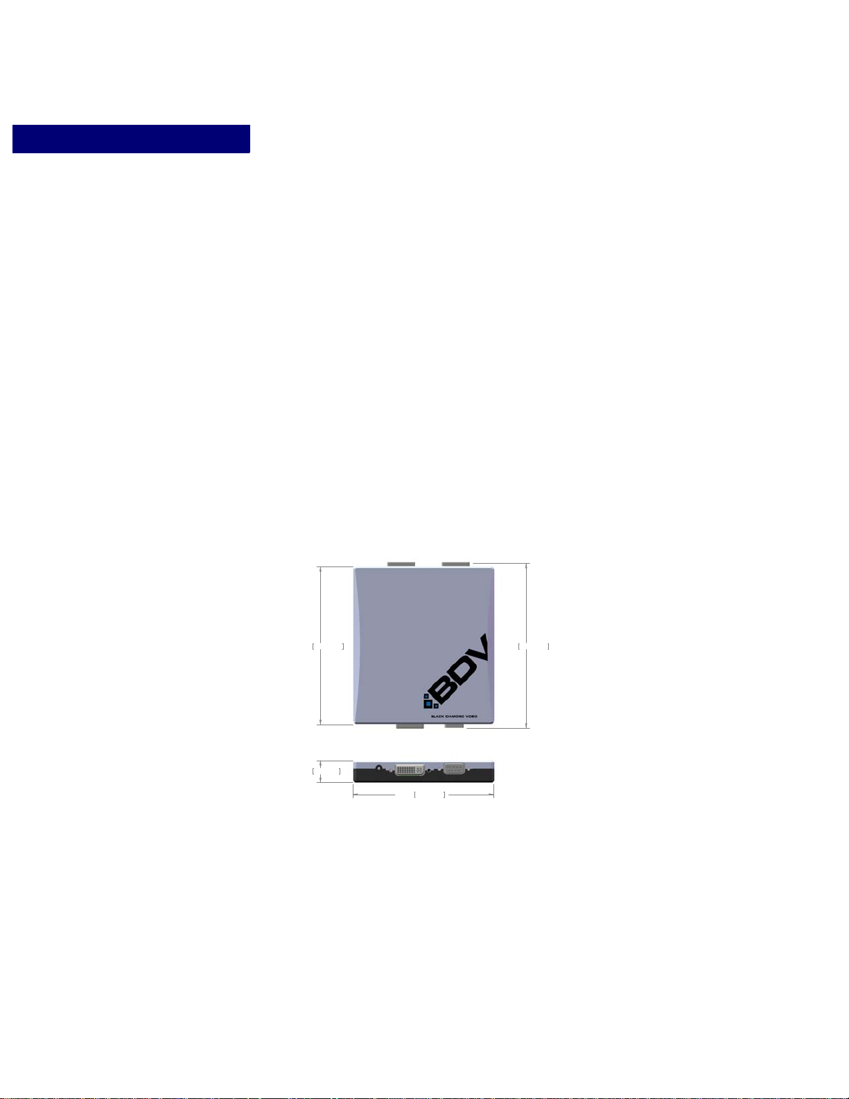
• 5.95” length x 4.7” width x 0.98” height (Figure 2)
2 Introduction Edition 1.01 DVI DL-DA Splitter: Installation & Operation Guide
FIGURE 2. DVI DL-DA Splitter dimensions
OUTPUT PANEL DETAIL
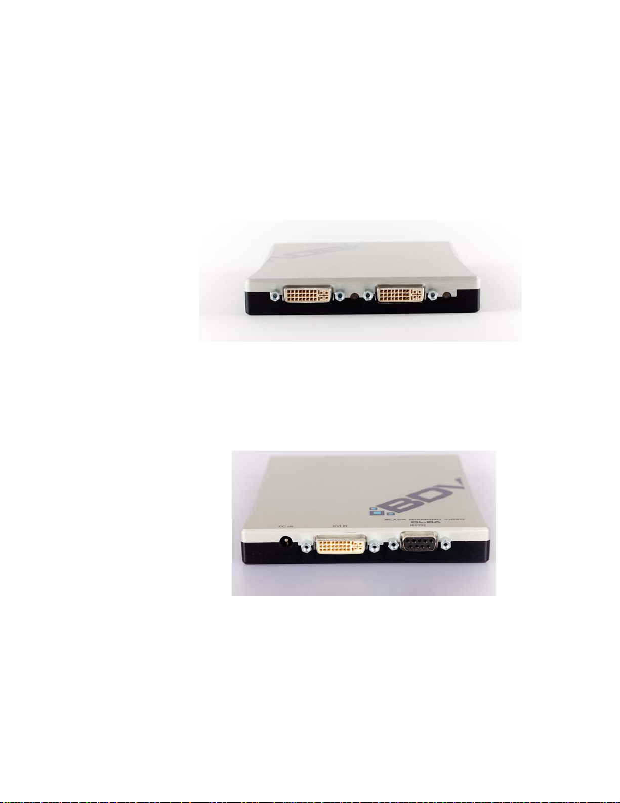
Figure 3 details the DVI output panel of the DVI DL-DA Splitter. This panel contains 2
DVI outputs and 2 Link status LED lights, one next to each DVI output. The Link status
Page 7
PRODUCT INFORMATION
. . . . . . . . . . . . . . . . . . . . . . . . . . . . . . . . . . . . . . . . . . . . . . . . . . . .
Video Input Detail
LEDs illuminate green when an active connection to the Splitter is established, and red to
indicate that an active video input connection exists.
FIGURE 3. DVI output panel of the DVI DL-DL Splitter
. . . . .
VIDEO INPUT DETAIL
Figure 4 details the video input panel of the DVI DL-DA Splitter. This panel also contains
the RS-232 serial port and the DC power input connector.
FIGURE 4. DVI input panel of the DVI DL-DL Splitter
DVI DL-DA Splitter: Installation & Operation Guide Edition 1.01 Introduction 3
Page 8

PRODUCT INFORMATION
. . . . . . . . . . . . . . . . . . . . . . . . . . . . . . . . . . . . . . . . . . . . . . . . . . . .
Customer Service and Support
CUSTOMER SERVICE AND SUPPORT
For technical support and service, contact Black Diamond Video at:
Black Diamond Video
503 Canal Blvd.
Point Richmond, California, 94804
Phone: (510) 439-4500
Fax: (510) 439-4599
Visit us on the web at www.blackdiamondvideo.com.
4 Introduction Edition 1.01 DVI DL-DA Splitter: Installation & Operation Guide
Page 9
. . . . .
. . . . . . . . . . . . . . . . . . . . . . . . . . . . . . . . . . .
I
. . . . . . . . . . . . . . . . . . . . . . . . . . . . . . . . . . . . . . . . . . . . . . . . . . . .
NSTALLATION
I
NSTRUCTIONS
This chapter tells you how to install your DVI DL-DA Splitter and establish RS-232
control.
IMPORTANT!
DVI DL-DA SPLITTER INSTALLATION
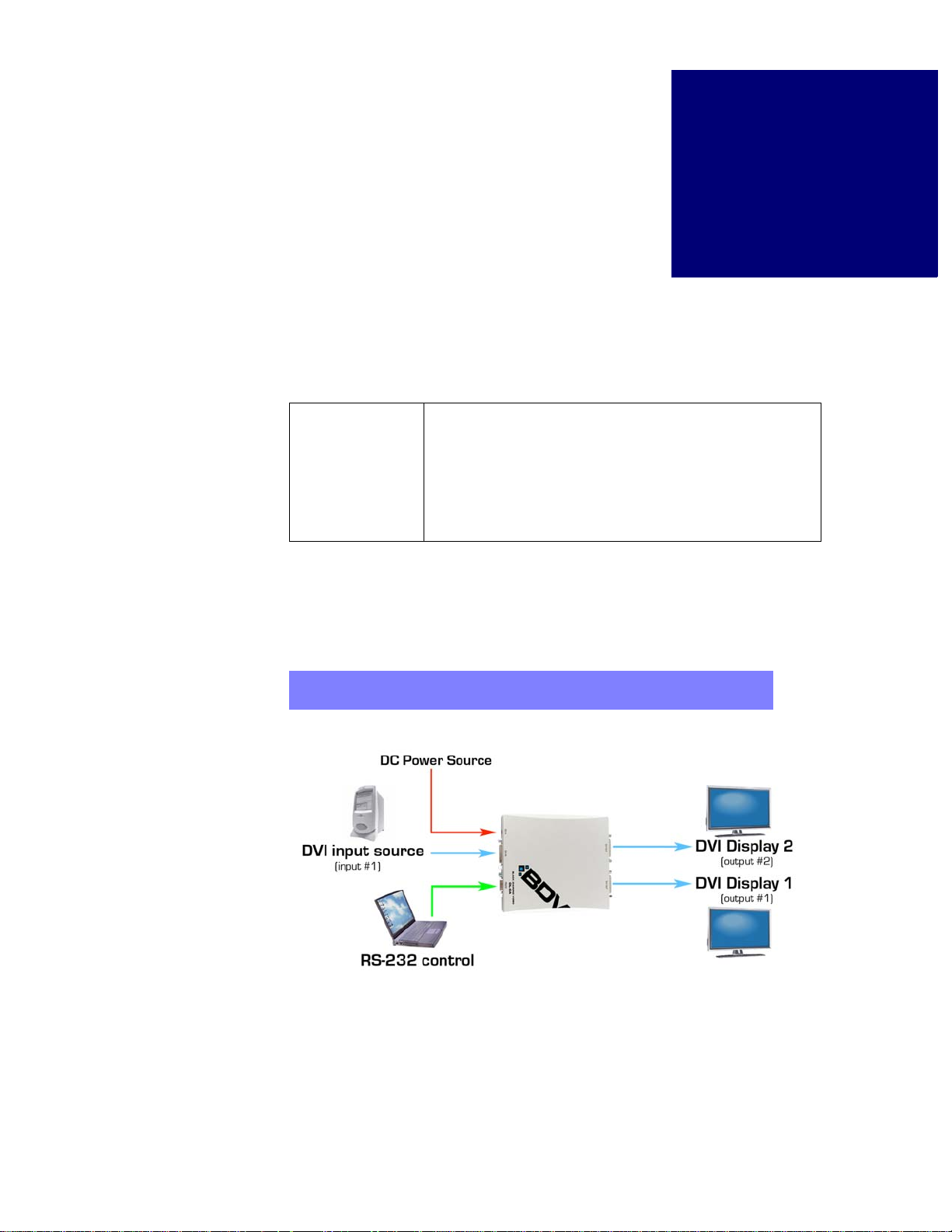
Figure 5 illustrates the installation of the DVI DL-DA Splitter. The following procedure
describes the installation process.
2
This product must be tested with the intended equipment
before being permanently installed. Failure to do so voids any
warranty and limited liability. Although Black Diamond V ideo
tests the product to its fullest extent, situations may arise
giving marginal results or potential compatibility issues when
used with digital video display devices that are non-compliant
or incompatible.
NOTE:
DVI DL-DA Splitter: Installation & Operation Guide Edition 1.01 Installation 5
The DVI DL-DA Splitter should be connected as close to the video source
as possible to minimize cable problems such as noise and attenuation.
FIGURE 5.
DVI DL-DA Splitter installation
Page 10

INSTALLATION INSTRUCTIONS
. . . . . . . . . . . . . . . . . . . . . . . . . . . . . . . . . . . . . . . . . . . . . . . . . . . .
Establishing RS-232 Control
To Install the DVI DL-DA Splitter
1 Before installing the DVI DL-DA Splitter, connect the supplied power adapter to the unit
and plug it into a DC power source. Black Diamond Video recommends the use of a
surge protector.
2 Connect your transformer to the Splitter.
3 Connect a DVI video source to the DVI input connector.
4 Connect up to 2 DVI display devices to the Splitter’s DVI output connectors using Black
Diamond Video-tested DVI cable.
Alternatively, connect the other end of the DVI cable directly to the Black Diamond Video digi-
tal video processing equipment in your installation, such as the Phantom 800 or CXPS.
5 The Link LED indicators on the DVI DL-DA Splitter flash green when an active
connection to the DL-DA Splitter is established.
Installation of the DVI DL-DA Splitter is complete.
ESTABLISHING RS-232 CONTROL
Setup of the DVI DL-DA Splitter should be done using RS-232 control. The following
procedure details how to establish RS-232 serial control of the DVI DL-DA Splitter.
1 Connect the supplied RJ11 to DB9 cable to the DVI DL-DA Splitter.
2 Connect the control computer to the RS-232 DB9 connector on the supplied cable.
3 Open up a serial port terminal on the control computer.
On Microsoft Windows, you can use HyperTerminal for serial communications.
4 Configure the port settings as follows:
• Baud: 9600
• Data bits: 8
• Parity: None
• Stop bits: 1
• Flow control: None
The RS-232 connection to the DVI DL-DA Splitter is established and the Splitter can be con-
trolled using the RS-232 command set found in Appendix A, “RS-232 Protocol.”
NOTE:
To avoid recreating the connection parameters each time you reestablish
RS-232 connection to the CXPS, you can save the connection for
subsequent control sessions.
6 Installation Edition 1.01 DVI DL-DA Splitter: Installation & Operation Guide
Page 11
. . . . .
. . . . . . . . . . . . . . . . . . . . . . . . . . . . . . . . . . .
RS-232 P
. . . . . . . . . . . . . . . . . . . . . . . . . . . . . . . . . . . . . . . . . . . . . . . . . . . .
ROTOCOL
A
DVI DL-DA SPLITTER COMMAND SET
The DVI DL-DA Splitter is controlled by using RS-232 protocol. Commonly used
commands are presented and defined in the following tables covering image control, input
and host timing control, and general system commands.
Arguments in [square brackets] are optional. Arguments in <angle brackets> are required.
For example, typing hlist by itself displays all host timing values. Typing hlist 501
returns the host timing for host 501. Typing inputsave with no arguments returns an
error because the inputsave command requires the <inputnum> argument.
Commands can be entered using either the full command name or the abbreviated syntax.
For example, to restore default settings, you could type either restoredefault or
rfd.
NOTE:
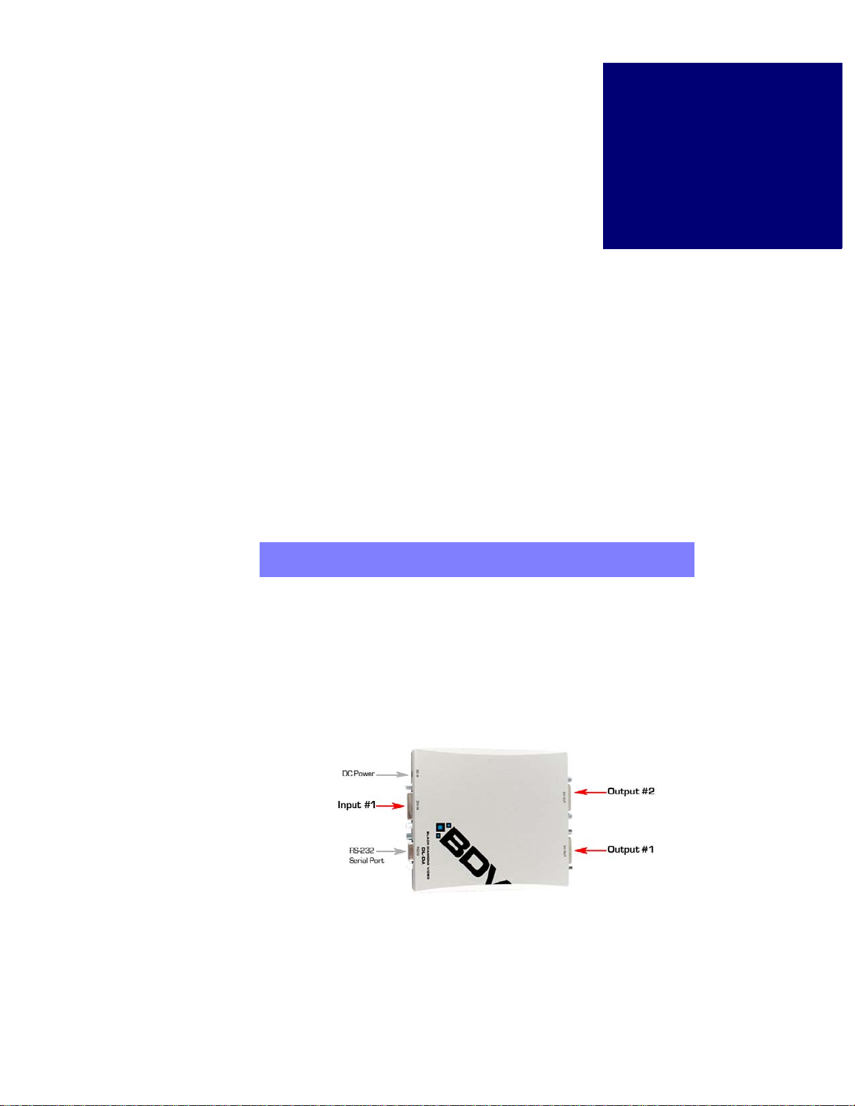
INPUT AND OUTPUT NUMBER ASSIGNMENT
Some commands require the number of the involved input and/or output. Input and output
numbers are assigned as follows (Figure 6):
• The input is considered Input 1.
• The output across from the input is Output 2.
• The output across from the serial port is Output 1.
RS-232 commands are not case-sensitive. Capitalization of either the
commands or the parameters does not matter.
FIGURE 6.
DVI DL-DA I/O Arrangement
DVI DL-DA Splitter - Installation & Operation Guide Edition 1.01 Reference 7
Page 12

RS-232 PROTOCOL
. . . . . . . . . . . . . . . . .
. . . . . . . . . . . . . . . . . . . . . .
. . . . . . . . . . . . . . . . . . . . . .
. . . . . . . . . . . . . . . . .
. . . . . . . . . . . . . . . . . . . . . .
. . . . . . . . . . . . . . . . . . . . . .
. . . . . . . . . . . . . . . . .
. . . . . . . . . . . . . . . . . . . . . .
. . . . . . . . . . . . . . . . . . . . . .
DVI DL-DA Splitter Command Set
HOST COMMANDS
Command Abbreviated Command Syntax Action
CREATEOUTPUTHOST COUTHOST <host> <name>
HOSTLIST HLIST [host] Displays one or all default input hosts.
OUTPUTLIST OUTLIST [host] Displays one or all local output hosts.
OUTPUTLISTDEL OUTLISTDEL <host> Deletes a local output host.
OUTPUTNAME OUTN <HOST> <HOSTNAME> Names a local host.
OUTPUTSAVE OUTS <HOST> Saves to a local host.
INPUT AND OUTPUT COMMANDS
Command Abbreviated Command Syntax Action
GETDVIINTIMING GDIT Returns the timing at the DVI input
INPUTTIMING INT Returns the input timing. If a valid input
<hfp> <hs> <hbp> <hact>
<vfp> <vs> <vbp> <vact>
<hfreq> <sync> <phase>
<vpol> <hpol> <interlace>
Creates an output host timing with the
specified parameters.
<host> is a value from 501 to 540.
<name> is limited to 16 characters.
<hfreq> in Hz.
<sync> is 3,4, or 5 wire.
<vpol> is vertical sync polarity; 1 =
positive, 0 = negative.
<hpol> is horizontal sync polarity.
<interlace> is 1 = interlaced, 0 =
non-interlaced.
channel.
signal is not present, no values are
returned.
SYSTEM COMMANDS
Command Abbreviated Command Syntax Action
CUSTOMEDID CEDID <input #> <host #> Sets the EDID timing from the host table.
COPYEDID CPEDID <output #> <input #> Copies the EDID from the output to the
8 Reference Edition 1.01 DVI DL-DA Splitter - Installation & Operation Guide
Use when you know the host number.
<input #> is 1.
input. NOTE: Before issuing this
command, disconnect the input from the
DVI source.
<input #> is 1.
<output #> is 1 or 2.
Page 13

SYSTEM COMMANDS
. . . . . . . . . . . . . . . . .
. . . . . . . . . . . . . . . . . . . . . .
. . . . . . . . . . . . . . . . . . . . . .
Command Abbreviated Command Syntax Action
RS-232 PROTOCOL
DVI DL-DA Splitter Command Set
. . . . .
GETEDID GEDID <output #> Returns the EDID data from the display
HELP help Lists all user commands.
ID id Returns system information: model,
OVERRIDE override <dl/sl/off> Forces dual link (dl), single link (sl), or
PROGEDID PROGEDID <sl/dl> Sets input EDID to default for
RDINEDID RDINEDID Displays the EDID on the input.
RESTOREDEFAULT rfd Restores the factory defaults.
device connected to the selected output
channel (1 or 2).
manufacturing date, serial number, and
firmware version.
no override.
single/dual link.
NOTE: This deletes all stored hosts.
DVI DL-DA Splitter - Installation & Operation Guide Edition 1.01 Reference 9
Page 14

RS-232 PROTOCOL
DVI DL-DA Splitter Command Set
10 Reference Edition 1.01 DVI DL-DA Splitter - Installation & Operation Guide
 Loading...