

Page 1
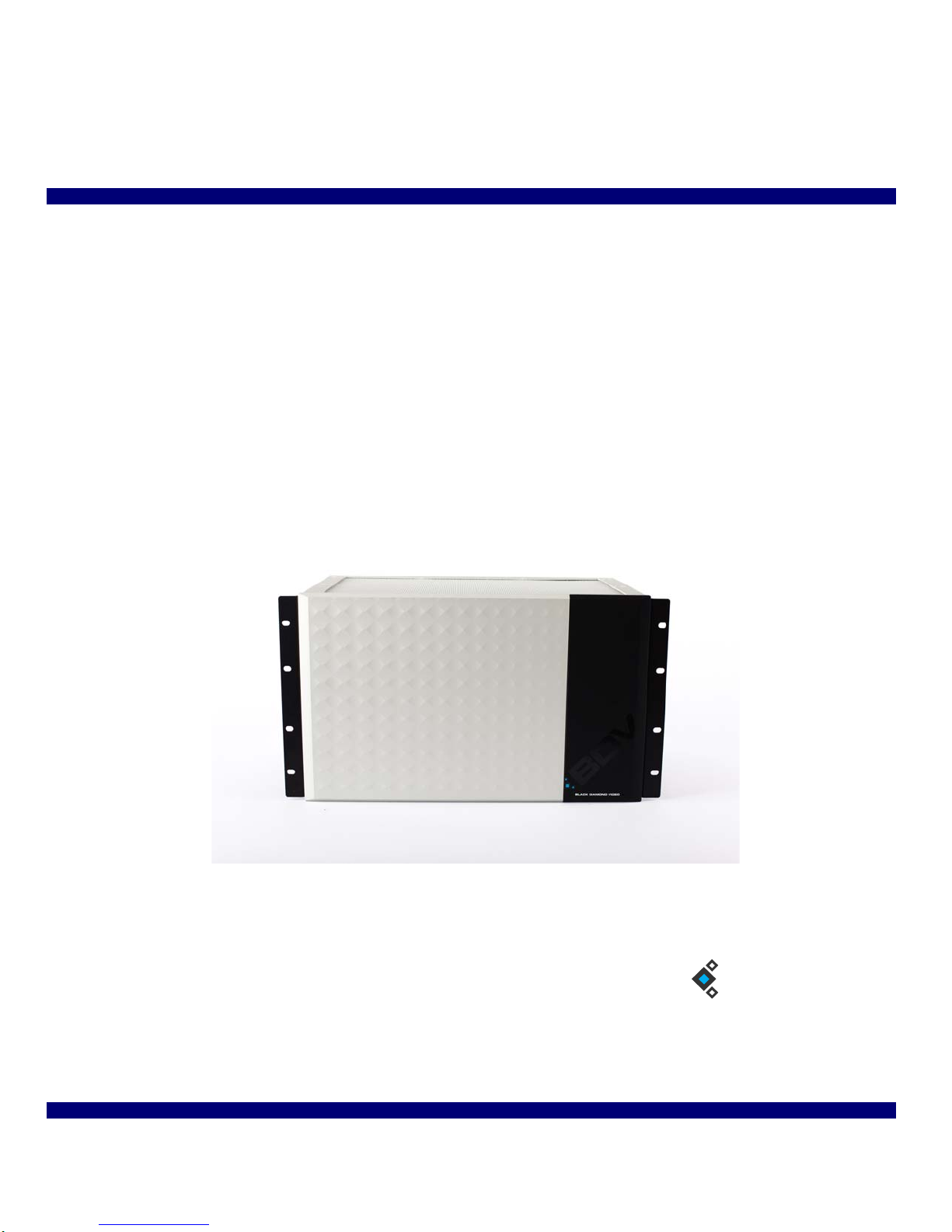
CXPS Manual
BDV
BLACK DIAMOND VIDEO
Edition 1.07
August 10, 2011
Page 2

Trademarks
The Black Diamond Video logo and CXPS are registered trademarks of Black Diamond Video, Inc.
Warranty
Warranty and Warranty Disclaimer: Black Diamond Video warrants to the original purchaser ("Buyer") that the products
delivered by Black Diamond Video that accompany this manual ("Products") will be in accordance with Black Diamond
Video’s published specifications under normal use and service for a period of one (1) year from delivery. Deviations from
published specifications which do not materially affect performance of Products covered hereby shall not be deemed to
constitute defects of material or workmanship or a failure of Products to comply with such specifications. Warranty claims
and the return of Products under warranty shall be subject to, and governed by, Black Diamond Video’s return material
authorization (RMA) policy. This warranty shall not apply to any Product that has been subject to misuse or neglect or
damaged by weather or accident (including, without limitation, damage due to fall, fire, exposure to water and abnormal
electrical exposure), or that has been modified by anyone other than Black Diamond Video. The warranties contained herein
shall extend only to Buyer and shall not apply to Buyer’s affiliates or customers or subsequent purchasers. SELLER’S
ENTIRE LIABILITY, AND BUYER'S SOLE AND EXCLUSIVE REMEDY, SHALL BE LIMITED SOLELY TO
SELLER, AT ITS OPTION AND ELECTION, REPAIRING OR REPLACING THE DEFECTIVE PRODUCT.
WARRANTY CLAIMS MUST BE MADE WITHIN THE WARRANTY PERIOD OR ARE FOREVER WAIVED.
EXCEPT FOR THE EXPRESS WARRANTY MADE IN THIS PARAGRAPH, BLACK DIAMOND VIDEO
EXPRESSLY DISCLAIMS AND EXCLUDES ALL WARRANTIES, WHETHER STATUTORY, EXPRESS OR
IMPLIED, INCLUDING, BUT NOT LIMITED TO, THE IMPLIED WARRANTIES OF MERCHANTABILITY,
FITNESS FOR A PARTICULAR PURPOSE AND NON-INFRINGEMENT OF THIRD PARTY RIGHTS WITH
RESPECT TO THE PRODUCTS FURNISHED BY BLACK DIAMOND VIDEO HEREUNDER AND ALL
WARRANTIES WHICH, BUT FOR THIS PROVISION, MIGHT ARISE FROM COURSE OF DEALING, CUST OM OR
TRADE OR THAT ARE OTHERWISE IMPLIED BY LAW. Certain jurisdictions do not permit the disclaimer of certain
warranties, so this limitation may not apply to Buyer.
Limitation of Liability. IN NO EVENT SHALL BLACK DIAMOND VIDEO BE LIABLE FOR ANY
CONSEQUENTIAL, INCIDENTAL, INDIRECT, EXEMPLARY, PUNITIVE OR SPECIAL DAMAGES
WHATSOEVER ARISING OUT OF, IN CONNECTION WITH OR RESULTING FROM THE FURNISHING,
PERFORMANCE OR USE OF THE PRODUCTS, WHETHER DUE TO BREACH OF CONTRACT, BREACH OF
WARRANTY, STRICT LIABILITY, PRODUCT LIABILITY, THE NEGLIGENCE OF SELLER OR OTHERWISE. IN
NO EVENT SHALL SELLER’S LIABILITY EXCEED THE U.S. DOLLAR AMOUNT EQUAL TO THE AMOUNT
PAID BY BUYER FOR THE APPLICABLE PRODUCT. THE DAMAGE LIMITATIONS PROVIDED AND THE
REMEDIES STATED HEREIN SHALL BE EXCLUSIVE AND SHALL BE BUYER’S SOLE REMEDY. THESE
LIMIT ATIONS SHALL SURVIVE FAILURE OF ANY ESSENTIAL PURPOSE. Certain jurisdictions do not permit the
limitation of certain types of liability, so this limitation may not apply to Buyer.
Edition 1.07 CXPS Manual
Page 3

. . . . .
. . . . . . . . . . . . . . . . . . . . . . . . . . . . . . . . . . .
Contents
Chapter 1 Welcome ...................................................1
About this Manual....................................................... 1
Safety Information and Instructions ........................ 1
Customer Service and Support.................................... 2
Chapter 2 Product Information ................................3
Introducing the CXPS ..............................................3
Key Features ............................................................ 4
Front Panel Detail ................................................... .5
Rear Panel Detail ..................................................... 6
Options .................................................................... 8
Product Specifications ............................................. 8
Chapter 3 Configuration Options ...........................11
Video Options ........................................................ 11
USB Options .......................................................... 14
Chapter 4 Getting Ready to Install .........................15
Overview of the Installation Process ..................... 15
System Test Installation Overview ........................ 15
Final System Installation Overview ...................... 17
Using DVI Converters ........................................... 18
Using Black Diamond Cable and Cable Kits ........ 18
Chapter 5 Installation Instructions ........................21
System Test Installation ........................................ 21
Final System Installation ....................................... 25
System Reset .........................................................34
Changing I/O Card Configuration............................. 34
CXPS Manual Edition 1.07 Contents iii
Page 4

Startup Macro............................................................35
Chapter 6 About the Web-Server GUI.......................37
Accessing the GUI..................................................... 37
Appearance and Functions of the GUI...................... 38
Chapter 7 Matrix Switching ....................................41
About Matrix Switching ........................................ 41
Matrix Switching Control: GUI ............................. 41
Matrix-Switching Control: RS-232 and Telnet......... 43
Chapter 8 Video Scaling .........................................47
About Video Scaling .............................................47
Auto-Resolution Display ....................................... 47
Preset Video Positioning ....................................... 48
Custom Video Positioning ..................................... 51
Pan and Zoom ................................................ .... ....51
Advanced Video Scaling Operations ..................... 53
Chapter 9 Video Windowing ......................................55
About Video Windowing .......................................... 55
Output Timing Synchronization................................57
Standard Window Function....................................... 59
Picture-In-Picture ...................................................... 60
Turning a Window On/Off........................................ 62
Window Identity........................................................ 62
Window Priority........................................................62
Window Position and Size.........................................64
Zooming and Panning Within a Window.................. 71
Cropping.................................................................... 73
Chapter 10 Dissolve and Force Effects ......................77
About Dissolve And Force........................................ 77
Output Timing Synchronization................................78
Dissolve and Force.................................................... 81
iv Contents Edition 1.07 CXPS Manual
Page 5

Chapter 11 Wall Processing.........................................89
About Wall Processing.............................................. 89
Wall Display Output Arrangement............................ 89
Output Timing Synchronization................................90
Wall Processing Function.......................................... 91
Adjusting Wall Position ............................................ 93
Switching Input Sources............................................ 94
Appendix A RS-232 and 10/100T Protocol...................97
CXPS Command Set ............................................. 97
Using an External Controller ............................... 114
RS-232 Pinout .....................................................117
Appendix B Upgrading Firmware ...............................119
. . . . .
CXPS Manual Edition 1.07 Contents v
Page 6

vi Contents Edition 1.07 CXPS Manual
Page 7

. . . . .
. . . . . . . . . . . . . . . . . . . . . . . . . . . . . . . . . . .
W
. . . . . . . . . . . . . . . . . . . . . . . . . . . . . . . . . . . . . . . . . . . . . . . . . . . .
. . . . . . . . . . . . . . . . . . . . . . . . . . . . . . . . . . . . . . . . . . . . . . . . . . . .
. . . . . . . . . .
. . . . . . . . . . . . . . . . . . . . . . . . .
. . . . . . . . . . . . . . . . . . . . . . . . . . . . . .
ELCOME
ABOUT THIS MANUAL
This manual contains information about the CXPS digital video matrix switcher and video
processor. Material is presented under the following sections:
Section Chapters Description
1
Introduction Chapter 1, “Welcome.”
Chapter 2, “Product Information.”
Configuration Chapter 3, “Configuration Options.” Use this section to understand your product configuration
Installation Chapter 4, “Getting Ready to Install.”
Chapter 5, “Installation Instructions.”
Operation Chapter 6, “About the Web-Server GUI.”
Chapter 7, “Matrix Switching.”
Chapter 8, “Video Scaling.”
Chapter 9, “Video Windowing.”
Chapter 10, “Dissolve and Force Effects.”
Chapter 11, “Wall Processing.”
Reference AppendixA, “RS-232 and 10/100T Protocol.”
Appendix B, “Upgrading Firmware.”
Use this section to get to know this product manual,
understand key safety measures, and learn about the key
features and functionality of the CXPS.
options before you purchase, as well as learn about the
video signal handling and remote control capabilities. The
CXPS is a highly-configurable device and this section
details the available product options for video input and
output, and for CPU board and USB ports.
Use this section to learn about installing the CXPS.
Included in this section are both an overview of the
installation process, and detailed, step-by-step installation
instructions.
Use this section to learn about the digital video processing
capabilities of the CXPS. Get an introduction to the webserver GUI and detailed instructions on how to use the
matrix switching, video scaling, video windowing,
dissolve and force, and wall processing features.
Use this section to refer to detailed remote control
command set information, RS-232 pinout information,
and firmware upgrade information and instructions.
SAFETY INFORMATION AND INSTRUCTIONS
The following safety instructions are to ensure the safety of personnel using this equipment
and to protect this device and working environment from potential damage.
CAUTION!
1 ELECTRIC SHOCK HAZARD. DO NOT OPEN.
2 REMOVAL OF COVER MAY RESULT IN ELECTRIC SHOCK. There are no user-
serviceable parts inside. Contact Black Diamond Video for authorized repair service.
CXPS Manual Edition 1.07 Introduction 1
Page 8

WELCOME
. . . . . . . . . . . . . . . . . . . . . . . . . . . . . . . . . . . . . . . . . . . . . . . . . . . .
Customer Service and Support
IMPORTANT SAFETY INFORMATION:
• Read and follow all instructions – Read all safety and operating instructions before
operating this equipment. Follow all operating instructions in this manual and adhere to
all warnings on the equipment and in this manual.
• Keep all documentation – Retain the User’s Manual and accompanying safety
instructions for future reference.
• Maintain proper ventilation – This equipment should be maintained in a well-ventilated
room with adequate air flow. Do not obstruct the ventilation slots on the device.
• Keep away from heat – Do not place this device near a heat source . Fa ilure to comply
could result in overheating and damage to the equipment.
• Keep away from water and moisture – Do not place this equipment near areas of running
water or dense condensation.
• Cleaning – Unplug the device before cleaning. The device can then be wiped with a
water-dampened soft cloth.
• Proper electrical grounding – This device must be plugged into a properly grounded
outlet in order to avoid electric shock. Do not bypass the grounding features of the power
cable or plug. When using an extension cord, make sure the cord is designed for
grounded plugs.
CUSTOMER SERVICE AND SUPPORT
For technical support and service, contact Black Diamond Video at:
Black Diamond Video
1000 Atlantic A ve, Suite 114
Alameda, California, 94501
Phone: (510) 769-2959
Fax: (510) 769-2949
Visit us on the web at www.blackdiamondvideo.com.
2 Introduction Edition 1.07 CXPS Manual
Page 9
. . . . .
. . . . . . . . . . . . . . . . . . . . . . . . . . . . . . . . . . .
P
. . . . . . . . . . . . . . . . . . . . . . . . . . . . . . . . . . . . . . . . . . . . . . . . . . . .
RODUCT INFORMATION
INTRODUCING THE CXPS
The CXPS is an all-digital DVI processor that integrates seamless 36 x 36 DVI matrix
switching, post-output scaling, and video windowing into a single unit. When combined
with Black Diamond Video's DVI converters, the CXPS provides the same level of
switching, scaling, and windowing for any analog, SDI, or HD-SDI signal source
eliminating the need for multi-format switches and cables.
The CXPS supports DVI operation at the maximum TMDS rate of 1.65 Gb/s. The CXPS
works seamlessly with Black Diamond Video's DVI X-treme Cable Kits, allowing the
transmission of DVI signals over 60 meters of copper on both the input and output sides of
the processor.
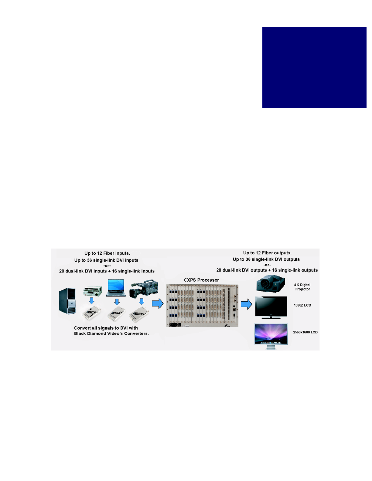
The CXPS system diagram (Figure 1) illustrates the full functionality of this DVI proce ssor
when combined with Black Diamond Video's DVI Converters and DVI X-treme Cable Kits.
2
FIGURE 1. CXPS System Diagram
CXPS Manual Edition 1.07 Introduction 3
Page 10

PRODUCT INFORMATION
. . . . . . . . . . . . . . . . . . . . . . . . . . . . . . . . . . . . . . . . . . . . . . . . . . . .
Key Features
KEY FEATURES
Features include the following:
SWITCHING
• Seamless, non-blocking 36 x 36 DVI matrix switching.
• Supports dual-link DVI matrix switching at the maximum TMDS rate of 2 x 1.65 Gb/s.
• Supports single-link DVI matrix switching at the maximum TMDS rate of 1.65 Gb/s.
• Input and output rates from 640 x 480 up to 3840 x 2400, interlaced or progressive.
IMAGE PROCESSING - VIDEO SCALING
• Output slots 1, 3, 5, 7 and 9 can be populated with one Quad Dual Link Scaler (QDLSC)
video processing card, for up to five cards.
• Auto-resolution display so that any video input will be displayed at its maximum
resolution and proper aspect ratio on any video monitor.
• Image controls include pan, zoom, position, contrast, brightness, and programmable
LUTS.
• Frame latency < 1.5 frames.
IMAGE PROCESSING - WINDOWING
• Each QDLSC video processing card can be equipped with video windowing
functionality.
• Windows can be arbitrarily sized, positioned, and prioritized smoothly, in real time.
• Transitional effects supported: alpha blending, wipe, and chroma keying.
• Chroma keying supported across multiple windows.
• QDLSC windowing cards can be used for a maximum of 36 windows, 4 windows per
card.
PHANTOM-POWER AND CONVERTER CONTROLS
• Phantom-power to Black Diamond Video’s DVI X-treme Cable Kits.
• Phantom-power and control for Black Diamond Video’s DVI Converters.
CONTROLS
• RS-232 serial
• 10/100T Ethernet
4 Introduction Edition 1.07 CXPS Manual
Page 11
GENERAL
. . . . . . . . . . . . . . . . . . . . . . . . . . . . . . . . . . . . . . . . . . . . . . . . . . . .
• 6U high, rack mountable
• Remote diagnostic capability
FRONT PANEL DETAIL
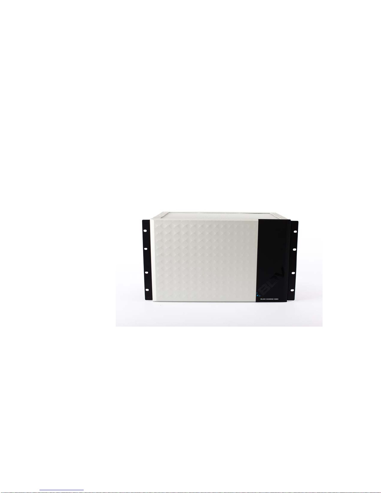
Figure 2 details the CXPS front panel.
PRODUCT INFORMATION
Front Panel Detail
. . . . .
FIGURE 2. CXPS Front Panel
CXPS Manual Edition 1.07 Introduction 5
Page 12
PRODUCT INFORMATION
. . . . . . . . . . . . . . . . . . . . . . . . . . . . . . . . . . . . . . . . . . . . . . . . . . . .
(3)
(4)
(8)
(7)
(6)
(5)
(1) (2)
(9)
(10)
Rear Panel Detail
REAR PANEL DETAIL
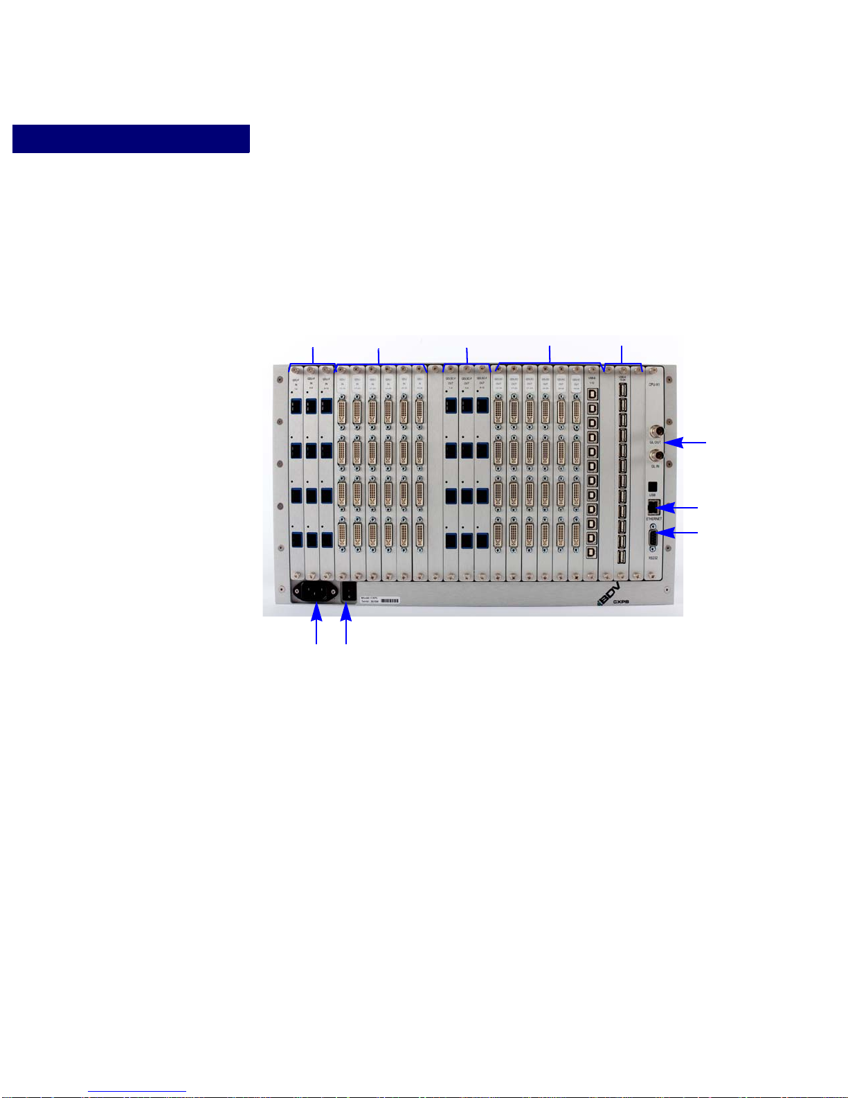
Figure 3 details a fully-equipped CXPS. Your device may be configured with fewer
connections.
FIGURE 3. CXPS Rear Panel Diagram
1 - AC POWER IN
AC input power connection (120/240 VAC).
2 - POWER SWITCH ON/OFF
The power switch is used to turn the unit on or off. The system status light on the front panel
indicates when the unit is powered on.
3 - DVI-I INPUT CONNECTIONS
The DVI-I input connectors are used to connect a video source to the CXPS. If the input
source is a DVI source, it can be connected directly to the device. If the input source is an
analog or SDI source, the signal must first be converted to DVI using a Black Diamond
Video DVI co nverter before connecting it to the CXPS.
6 Introduction Edition 1.07 CXPS Manual
Page 13

PRODUCT INFORMATION
Rear Panel Detail
On a fully-configured CXPS, Dual-Link DVI is supported on the following input
connectors: 1-4, 9-12, 17-20, 25-28, 33-36. Single-Link DVI is supported on all input
connectors.
For cable distances greater than seven meters, Black Diamond Video certified DVI cable
should be used. Black Diamond Video certified DVI cable is factory tested and guaranteed
for distances up to 60 meters. A DVI X-treme conditioner is not required on the input side
of the CXPS.
4 - DVI-O OUTPUT CONNECTIONS
The DVI-O output connectors are digital DVI outputs used to connect to a digital display
device. On a fully-configured CXPS, Dual-Link DVI is supported on the following output
connectors: 1-4, 9-12, 17-20, 25-28, 33-36. Single-Link DVI is supported on all output
connectors.
When connecting to a display device more than seven meters from the CXPS, a DVI Xtreme Cable Kit should be used with the DVI X-treme conditioner placed on the display side
of the cable.
. . . . .
5 - RS-232 SERIAL INTERFACE
The RS-232 interface is a DCE type used to control the CXPS by an external host over a
serial port or alternate RS-232 controller. A direct connect type RS-232 cable should be
used to connect the CXPS to a PC.
6 - 10/100T ETHERNET PORT
The 10/100T Ethernet port is used for controlling the CXPS from a remote location. This
port is also used for firmware upgrades in the field. The 10/100T Ethernet port can control
the CXPS through commands similar to the RS-232 port.
7 - GENLOCK INPUT/OUTPUT
The genlock I/O is used as an alternative external genlock source for the output scaler and
windowing cards. It is a general purpose +3.3V or +5V level genlock source.
8 - USB MATRIX SLOTS
Each USB matrix slot can accept a USB type B (input) or type A (output) card. Each card
supports 12 USB connectors.
9 - FIBER-I INPUT CONNECTIONS
The Fiber-I input connectors are used to connect a fiber video source to the CXPS.
10 - FIBER-O OUTPUT CONNECTIONS
The Fiber-O output connectors are fiber outputs used to connect to a fiber display device.
CXPS Manual Edition 1.07 Introduction 7
Page 14

PRODUCT INFORMATION
. . . . . . . . . . . . . . . . . . . . . . . . . . . . . . . . . . . . . . . . . . . . . . . . . . . .
. . . . . . . . . . . . . . . . . . . . . . . . . . . . . . . . . . . . . . . . . . . . . . . . . . . .
Options
OPTIONS
The following external options are available for the CXPS:
• DVI X-treme Cable and Cable Kits are phantom-powered and allow DVI signals to be
transmitted up to 60 meters on both the input and output sides of the switch for a
cumulative distance of 120 meters. Output cable kits are available in both single-link and
dual-link DVI format. These kits contain output cable and a DVI signal conditioner and
are used when the distance between the CXPS and the display device exceeds seven
meters. The dual-link DVI signal conditioner can accept both single-link and dual-link
DVI signals. The single-link DVI signal conditioner can only accept single-link DVI.
• Fiber Cable is required for use over distances exceeding 60 meters. Fiber optic cable
can be used in conjunction with DVI-Fiber and Fiber-DVI converters.
• SD-DVI Converter converts any standard-definition analog signal (NTSC, PAL) to
DVI. This converter is phantom-powered and is controlled and integrates seamlessly
with the CXPS.
• RGB-DVI Converter converts any analog RGB signal to DVI. This converter is
phantom-powered and is controlled and integrates seamlessly with the CXPS.
• SDI-DVI Converter converts any SDI or HD-SDI source to DVI. Thi s converter is
phantom-powered and is controlled and integrates seamlessly with the CXPS.
• Fiber-DVI Converter converts any fiber source to DVI. This converter is phantompowered and is controlled and integrates seamlessly with the CXP S .
• DVI-Fiber Converter converts any DVI source to fiber. This converter is phantompowered and is controlled and integrates seamlessly with the CXP S .
NOTE:
For information about configuration options for the CXPS, see Chapter 3,
“Configuration Options.”
PRODUCT SPECIFICATIONS
VIDEO SPECIFICATIONS
•Video Formats:
DVI Single-link, supports maximum TMDS rate of 1.65 Gb/s.
DVI Dual-link, supports maximum TMDS rate of 2 x 1.65 Gb/s.
• Video Resolution:
8 Introduction Edition 1.07 CXPS Manual
Page 15

PRODUCT INFORMATION
Product Specifications
Single-link DVI I/O rates 640x480 to 1920x1200, interlaced or progressive, 25-165
MHz.
Dual-link DVI, 165 - 333 MHz, I/O rates including: 3840 x 2400 33 Hz; 2560 x 1600 60
Hz; 2048 x 2160 60 Hz; 2048 x 1536 75 Hz; 2048 x 1080 120 Hz; 1920x 1080 85 Hz.
• Connectors: DVI-I female.
CONTROLS
• Serial Controls: RS-232 controls, DB9 female connector.
• Ethernet Controls: 10/100T Ethernet control, Protocols: Telnet, FTP.
GENERAL
• Dimensions/Weight: 6U, rack-mountable enclosure, 19.0"W x 14.6"D x 10.5"H, 43
pounds.
• Temperature Rating: 0-55° C.
. . . . .
• Power: 90-240 VAC, 47-63Hz, 1500 Watts, fully-loaded.
CXPS Manual Edition 1.07 Introduction 9
Page 16

PRODUCT INFORMATION
Product Specifications
10 Introduction Edition 1.07 CXPS Manual
Page 17
. . . . .
. . . . . . . . . . . . . . . . . . . . . . . . . . . . . . . . . . .
C
. . . . . . . . . . . . . . . . . . . . . . . . . . . . . . . . . . . . . . . . . . . . . . . . . . . .
ONFIGURATION
O
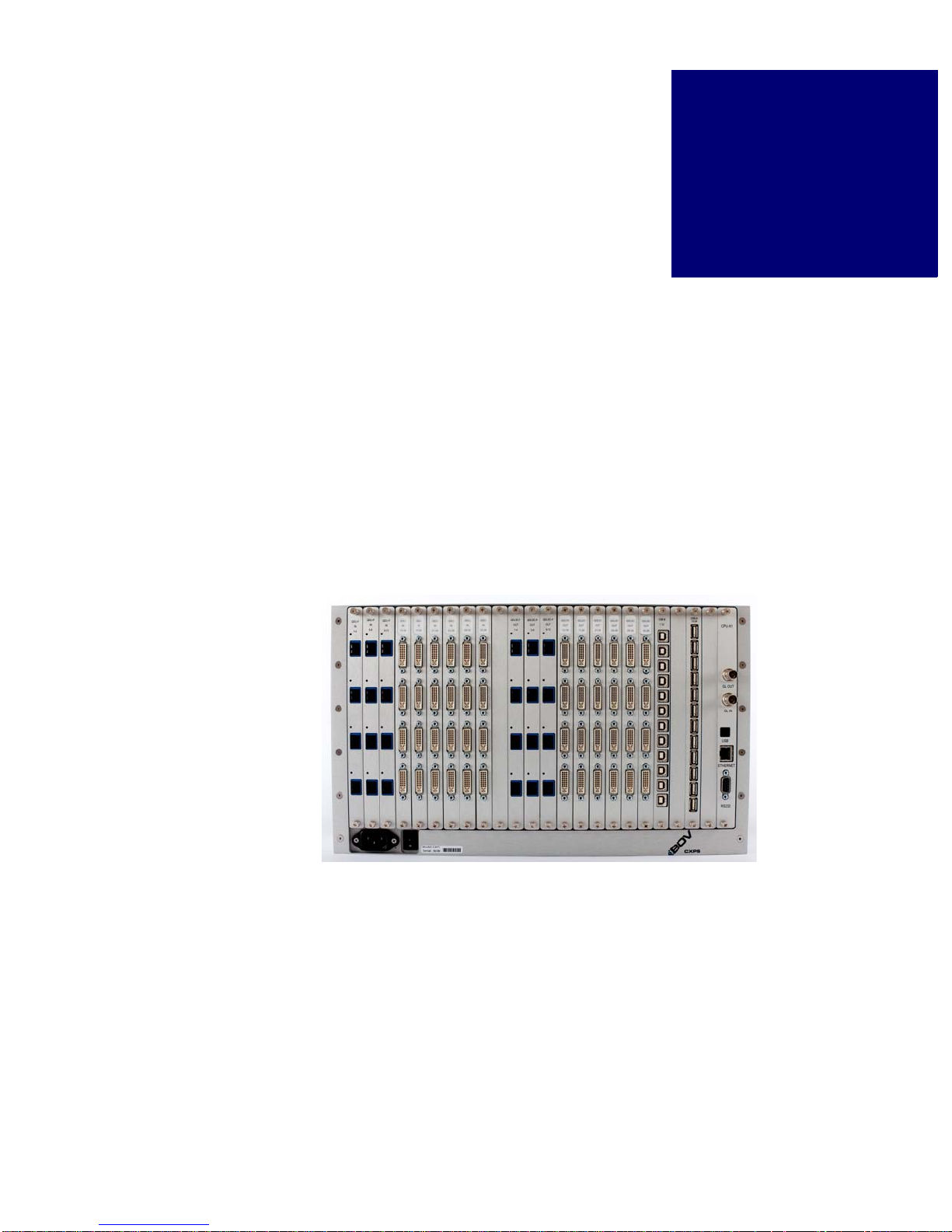
This chapter details the configuration options for the CXPS. The CXPS can be configured
for the following elements:
PTIONS
3
Video Input...
Video Output...
USB...
Figure 4 shows the back panel card and connector layout of the CXPS.
• Number of input channels and type (DVI or fiber)
• Number of output channels and type (DVI or fiber)
• Video scaler output cards
• Video windowing output option
• Number of Type B input channels
• Number of Type A output channels
FIGURE 4. CXPS Back Panel Board and Connector Layout
VIDEO OPTIONS
Your CXPS can be configured with input and output cards for up to 36 x 36 channels, as
shown in Figure 4. Both input and output cards contain four connectors each so your CXPS
can have any combination of inputs and outputs where each channel type is a multiple of
four, up to nine input cards and nine output cards.
CXPS Manual Edition 1.07 Configuration 11
Page 18
CONFIGURATION OPTIONS
Video Options
For example, your system could be configured as 4 x 4 (1 input card, 1 output card), 8 x 4 (2
input cards, 1 output card), 8 x 8 (2 input cards, 2 output cards), 12 x 4(3 input cards, 1
output card), 12 x 8 (3 input cards, 2 output cards), 12 x 12 (3 input cards, 3 output cards),
and so on.
Input and output cards are capable of supporting either single-link or dual-link DVI signals.
However, there are limitations to consider regarding dual-link inputs and outputs. These
limitations are discussed in “Dual-Link vs Single-Link”.
DUAL-LINK VS SINGLE-LINK
Dual-link DVI is only supported on odd-numbered slots. This applies to both input and
output channels. This means that on a fully-configured system with nine input cards and
nine output cards, the maximum number of dual-link DVI channels is 20 x 20. The input
and output channels on the cards in odd-numbered cards 1,3,5,7, and 9 would be dual-link
DVI-capable.
IMPORTANT!
Dual-link DVI is only supported on odd-numbered cards. This applies to both
input and output channels.
All input and output slots support single-link DVI. This means that the CXPS supports the
full 36 x 36 matrix for single-link DVI channels.
For example, let’s say you have a 16 x 8 system. Your CXPS would have four input cards
and two output cards (Remember, there are four channels per card). You could apply duallink DVI signals to the input channels in the cards in slots one and three, and you could
display those signals through the output channels on the card in slot one. Your total system
is 16 x 8 and it supports 8 x 4 dual-link DVI channels.
USING DVI AND FIBER CONVERTERS
The CXPS accepts DVI and fiber video inputs only. Black Diamond Video offers a line of
single-link DVI and Fiber converters which you can use to convert your Fiber, RGB, HD,
and SDI video signals to single-link DVI, or your DVI signals to Fiber. With the appropriate
converter, you can use any of these video formats as a source for the CXPS.
VIDEO INPUT OPTIONS
The CXPS can be configured with up to nine video input cards. Each card has four input
channels. By design, the video input card can accept either dual-link or single-link DVI, or
single-link fiber. However, the CXPS only supports dual-link DVI on cards installed in oddnumbered slots (as discussed in the previous section, “Dual-Link vs Single-Link”).
The input channels are numbered from left to right and top to bottom, so the card in slot
number one (the farthest left as you look at the back panel) contains input channel numbers
12 Configuration Edition 1.07 CXPS Manual
Page 19

CONFIGURATION OPTIONS
. . . . . . . . . . . . . . .
. . . . . . . . . . . . . . . . . . . . . . .
Video Options
1, 2, 3, and 4, counting from the top of the card to the bottom. The card in slot number two
contains input channel numbers 5, 6, 7, and 8, and so on up to 36.
VIDEO OUTPUT OPTIONS
The CXPS can be configured with up to nine video output cards. Each card has four output
channels. By design, the video output card can accept either dual-link or single-link DVI.
However, the CXPS only supports dual-link DVI on cards installed in odd-numbered slots
(as discussed in “Dual-Link vs Single-Link” above).
Like the input channels, output channels are numbered from left to right and top to bottom,
so the card in output slot number one (the one immediately to the right of the switch fabric
card as you look at the back panel) contains output channel numbers 1, 2, 3, and 4, counting
from the top of the card to the bottom. The card in slot number two contains input channel
numbers 5, 6, 7, and 8, and so on up to 36.
Currently, there ar e four video output card options. All four options come with four output
channels. New options are under development; contact Black Diamond Video for more
information.
. . . . .
Video Output Board Description
Repeater Standard DVI output (no processing). Used
Quad Single Link Scaler
(QSLS)
Quad Dual Link Scaler
(QDLS)
Fiber Output Card Single-link scaler card with fiber outputs.
for standard switching operation only
where the output exactly matches the input
signal.
For more information on the operation of
the repeater card, see Chapter 7, “Matrix
Switching.”
Video scaler single-link DVI output. Used
for scaling the input image up or down, and
also offers pan and zoom functionality.
For more information on the operation of
the QSLS card, see Chapter 8, “Video
Scaling.”
Video scaler dual-link DVI output. Used
for scaling the input image up or down, and
also offers pan and zoom functionality.
For more information on the operation of
the QDLS card, see Chapter 8, “Video
Scaling.”
Used for scaling the input image up or
down, and also offers pan and zoom
functionality.
For more information on the operation of
the Fiber Output Board, see Chapter 8,
“Video Scaling.”
CXPS Manual Edition 1.07 Configuration 13
Page 20
CONFIGURATION OPTIONS
. . . . . . . . . . . . . . . . . . . . . . . . . . . . . . . . . . . . . . . . . . . . . . . . . . . .
. . . . . . .
. . . . . . . . .
. . . . . . .
. . . . . . . .
USB Slots
USB Options
USB OPTIONS
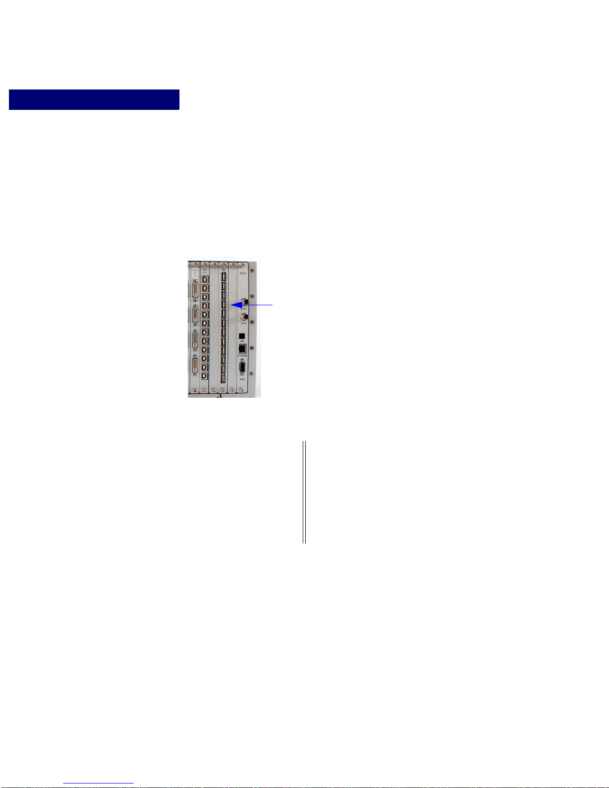
The CXPS has four USB slots (Figure 5). Each slot can accept a USB type B (input) or type
A (output) card. Each card supports 12 USB connectors. Your CXPS can be configured with
any combination of type B and type A USB cards, as long as there is at least one of each
type.
FIGURE 5. CXPS USB Slots
The supported USB configurations are:
USB Type B —
Input from PC
# Boards # Channels # Boards # Channels
224 112
224 224
112 224
112 112
14 Configuration Edition 1.07 CXPS Manual
USB Type A —
Output to PC
Page 21

. . . . .
. . . . . . . . . . . . . . . . . . . . . . . . . . . . . . . . . . .
G
. . . . . . . . . . . . . . . . . . . . . . . . . . . . . . . . . . . . . . . . . . . . . . . . . . . .
. . . . . . . . . . . . . . . . . . . . . . . . . . . . . . . . . . . . . . . . . . . . . . . . . . . .
ETTING
System Test Installation. Begin your installation process by performing a complete system test installation. The
Final System Installation. Complete the installation process by doing the final system installation. In this phase, you
R
EADY TO INSTALL
This chapter presents on overview of the installation process. Read this chapter to get an
introduction to how to install the CXPS. Included is information about using DVI
converters (required if you have video sources that are not in DVI format) and Black
Diamond cable kits.
For detailed installation instructions see Chapter 5 , “I nstallation Instructions.”
OVERVIEW OF THE INSTALLATION PROCESS
Installing the CXPS can be divided into two phases:
purpose of this phase is to establish remote control of the CXPS, and verify that all input
and output channels are working. You will use a single test video input and at least one of
the display devices you plan to use in your final system installation. You will verify that
your test video input is properly displayed on the display device when routed through each
input and output channel.
will install the CXPS in its final location. You will establish permanent remote control,
connect all necessary input and output cabling, apply all input sources (including any DVI
converters as necessary), and connect all display devices. Finally, you will verify that each
video source is properly displayed on each display device.
4
SYSTEM TEST INSTALLATION OVERVIEW
The system test installation should be performed first to verify your equipment is working
properly. It will also help you begin to plan for and organize the video sources, cabling
equipment, and display devices in preparation for the final system installation.
NOTE:
CXPS Manual Edition 1.07 Installation 15
This is an overview of the system test installation to help inform and
prepare you for the actual installation process. For detailed installation
instructions, see Chapter 5, “Installation Instructions.”
Page 22
GETTING READY TO INSTALL
System Test Installation Overview
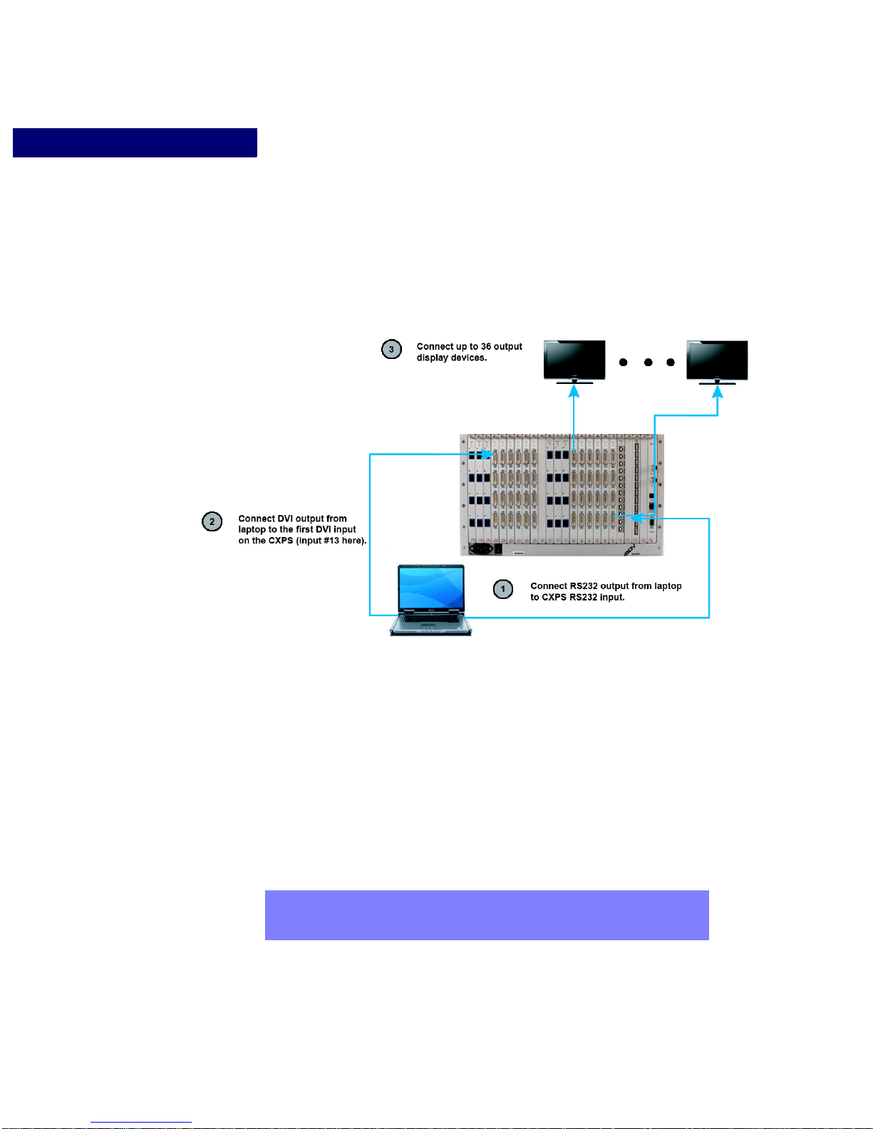
The system test installation consists of four steps. These steps are described below and
illustrated in Figure 6.
FIGURE 6. CXPS System Test Installation Diagram
Step 1. Establish Temporary Remote Control of the CXPS
Establish temporary remote control of the CXPS through a laptop computer or personal
computer using the RS-232 serial interface. This allows control of the CXPS so that the
video signals going into and out of the processor can be tested.
Step 2. Connect Test DVI and Test Fiber Input Sources
Connect one fiber video source to the first fiber input on the CXPS (if applicable). Connect
one DVI video source to the first DVI input on the CXPS. In Figure 6, the first fiber input is
input 1 and the first DVI input is input 13. Only a single DVI source and single fiber source
are required for the system test installation phase. Use Black Diamond Video tested DVI
and fiber cable to connect your test sources to the CXPS.
NOTE:
16 Installation Edition 1.07 CXPS Manual
If the computer you used in Step 1 has a DVI output, you can use it for the
test DVI video source in this step. This computer should have a built-in DVI
graphics card.
Page 23
GETTING READY TO INSTALL
. . . . . . . . . . . . . . . . . . . . . . . . . . . . . . . . . . . . . . . . . . . . . . . . . . . .
Final System Installation Overview
Step 3. Connect one or more Display Devices and Establish Video Output
Connect a fiber display device to the first fiber output on the CXPS. Connect additional
display devices as desired. Using the test fiber input connected in Step 2, use serial
commands to switch the input to each connected fiber display device. Verify that all video
displays or output devices (such as DVD recorders, etc) are functioning correctly.
Next, connect a DVI display device to the first DVI output on the CXPS. Connect additional
display devices as desired. Using the test DVI input connected in Step 2, use serial
commands to switch the input to each connected fiber display device. Verify that all video
displays or output devices (such as DVD recorders, etc) are functioning correctly.
Step 4. Test all Remaining Input Channels
Verify that all remaining input channels are functioning properly. Using the test fiber and
DVI video sources, connect to each input channel on your CXPS and then route the signal to
each connected display device.
. . . . .
FINAL SYSTEM INSTALLATION OVERVIEW
The final system installation should be performed after you have completed the system test
installation. You should have all of your video sources, cabling equipment, and display
devices assembled in preparation for the final system installation.
NOTE:
The final system installation consist s of four steps. These steps are described below.
Step 1. Place the CXPS into the Rackmount or Other Permanent Location
The CXPS can be installed in a 6U rackmount. Place your unit in its permanent location
before making any other system connections. Be sure to follow the safety warnings
regarding proper ventilation of the equipment.
IMPORTANT!
Step 2. Connect all Video Inputs
Connect all fiber and DVI sources directly to the CXPS input channels. All non-DVI, nonfiber sources must first be converted to DVI using a Black Diamond Video DVI Converter.
See “Using DVI Converters” on page 18 for more information.
This is an overview of system installation to help inform and prepare you for
the actual installation process. For detailed installation instructions, see
Chapter 5, “Installation Instructions.”
A 1U air gap must be allowed for above and below the CXPS for proper air
flow and cooling. Failure to do so may result in excessive heating and poor
system performance.
CXPS Manual Edition 1.07 Installation 17
Page 24

GETTING READY TO INSTALL
. . . . . . . . . . . . . . . . . . . . . . . . . . . . . . . . . . . . . . . . . . . . . . . . . . . .
. . . . . . . . . . . . . . . . . . . . . . . . . . . . . . . . . . . . . . . . . . . . . . . . . . . .
Using DVI Converters
All cabling from the DVI Converters to the CXPS should use Black Diamond Video tested
DVI cable. Black Diamond Video can not guarantee the quality of cable purchased from
other manufacturers. See “Using Black Diamond Cable and Cable Kits” on page 18 for
more information.
Step 3. Connect all Display and Output Devices
Connect all display and output devices to the CXPS output channels. All cabling from the
CXPS to the display devices should use Black Diamond Video tested DVI or fiber cable.
Black Diamond Video can not guarantee the quality of cable purchased from other
manufacturers. See “Using Black Diamond Cable and Cable Kits” on page 18 for more
information.
Step 4. Establish Permanent Remote Control
Establish permanent remote control to the CXPS using RS-232, 10/100T Ethernet control,
or the web-server GUI.
Step 5. Test all Input/Output Switching Configurations
Route each input to each output in turn and verify the video displays properly on the display
device. If video output option cards are installed, test the video processing functions of these
cards.
USING DVI CONVERTERS
The CXPS accepts DVI and fiber video inputs only. Black Diamond Video offers a line of
single-link DVI and Fiber converters which you can use to convert your Fiber, RGB, HD,
and SDI video signals to single-link DVI, or your DVI signals to Fiber. With the appropriate
converter, you can use any of these video formats as a source for the CXPS.
The converter should be located as close to the video source as possible to eliminate cabling
problems such as attenuation and noise. See “Options” on page 8 for more information
about the available DVI converters.
USING BLACK DIAMOND CABLE AND CABLE
KITS
When using Black Diamond Video DVI cable kits, signal conditioners should be applied
within the last three meters of copper DVI cabling before each display device. Black
Diamond Video offers both single-link DVI and a dual-link DVI cable kits which include
Black Diamond Video tested DVI copper cable and a signal conditioner.
18 Installation Edition 1.07 CXPS Manual
Page 25

GETTING READY TO INSTALL
Using Black Diamond Cable and Cable Kits
Black Diamond Video’s Fiber Optic cable should be used for distances over 60 meters.
See “Options” on page 8 for more information about cable and cable kit options.
. . . . .
CXPS Manual Edition 1.07 Installation 19
Page 26

GETTING READY TO INSTALL
Using Black Diamond Cable and Cable Kits
20 Installation Edition 1.07 CXPS Manual
Page 27

. . . . .
. . . . . . . . . . . . . . . . . . . . . . . . . . . . . . . . . . .
I
. . . . . . . . . . . . . . . . . . . . . . . . . . . . . . . . . . . . . . . . . . . . . . . . . . . .
NSTALLATION
System Test Installation. Begin your installation process by performing a complete system test installation. The
Final System Installation. Complete the installation process by doing the final system installation. In this phase, you
I
NSTRUCTIONS
This chapter tells you how to install your CXPS system. You should read Chapter 4
“Getting Ready to Install” first to familiarize yourself with the installation process.
The installation of your CXPS should be conducted in two phases:
purpose of this phase is to establish remote control of the CXPS, and verify that all inputs
and outputs are working. You will use a single test video input and one of the display
devices you plan to use in your final system installation. You will verify that your test video
input is properly displayed on the display device when routed through each of the input and
output channels.
will install the CXPS in its final location. You will connect all necessary input and output
cabling, apply all input sources (including any DVI converters as necessary), connect all
display devices, and establish permanent remote control.
SYSTEM TEST INSTALLATION
5
Complete a thorough test of your CXPS equipment before doing the final system
installation. The system test installation consists of the following series of steps:
Step 1: AC Power Connection and System Power Up
WHAT YOU WILL NEED FOR THIS STEP
• Power cord (supplied)
• Surge protector (recommended)
• Line conditioner (recommended)
DESCRIPTION
Begin your system test installation by connecting the CXPS to an AC power supply and
powering it up.
1 Connect the power cord (supplied) to the AC input on the CXPS.
2 Plug the power cord into a surge protector (recommended).
3 Plug the surge protector into a conditioned AC power source.
CXPS Manual Edition 1.07 Installation 21
Page 28

INSTALLATION INSTRUCTIONS
System Test Installation
4 Turn on the CXPS using the power switch on the rear panel.
The status button on the front panel turns blue or green when the CXPS CPU is initialized and
ready.
Step 2: Establish Test Remote Control
WHAT YOU WILL NEED FOR THIS STEP
• Laptop or personal computer with a serial port
• RS-232 direct-connect type serial cable with DB9 (male) connector
DESCRIPTION
The CXPS can be controlled over either an RS-232 or a 10/100T Ethernet connection. For
initial testing of this equipment, Black Diamond Video recommends temporary control of
the CXPS with a laptop computer using a RS-232 terminal program. Using the RS-232
interface and command set allows for the easy set-up and rapid ability to debug any
installation problems.
1 Connect a laptop or PC to the CXPS RS-232 serial interface using a direct-connect type
cable.
2 Open up a serial port terminal on the laptop or PC connected to the CXPS. For
Microsoft Windows-based programs access this with Start > All Programs >
Accessories > Communications > Hyperterminal.
The New Connection window appears.
3 Enter a name for your connection and choose an icon.
4 Click OK.
The Connect To window appears.
5 In the Connect using field, select COM port to which you have connected the CXPS.
6 Click OK.
The Port Settings window appears.
7 Configure the settings as follows:
• Baud: 9600
• Data bits: 8
• Parity: None
• Stop bits: 1
• Flow control: None
8 Click Apply.
22 Installation Edition 1.07 CXPS Manual
Page 29

INSTALLATION INSTRUCTIONS
The RS-232 connection to the CXPS is established and the processor can be controlled using
the RS-232 command set found in Appendix A, “RS-232 and 10/100T Protocol.”
Step 3: Connect and Test a DVI and a Fiber Input on all Output Channels
WHAT YOU WILL NEED FOR THIS STEP
• DVI video input source. Black Diamond Video recommends that, for this DVI input
source, you use the same laptop or personal computer that is being used to temporarily
control the CXPS.
• Display device capable of displaying a DVI video input signal.
• DVI cable.
• (Optional) DVI signal conditioners. If the distance to the display requires more than
seven meters of DVI cable, a Black Diamond Video DVI X-treme Cable Kit should be
used with the DVI X-treme II Conditioner and appropriate length of cable provided in
the DVI cable kit.
• Fiber video input source (if the CXPS has fiber inputs).
System Test Installation
. . . . .
• Display device capable of displaying a fiber video input signal (if the CXPS has fiber
outputs).
• Fiber optic cable.
• RS-232 Commands:
SW
<input> <output>
DESCRIPTION
For the system test installation, apply a single DVI test video input signal and a single fiber
test video input signal. Connect at least one of the display devices you plan to use in your
final system installation. Verify that your test video input is properly displayed on the
display device when routed through each input and output channel. The easiest method to
ensure transmission is to connect a reliable video source directly to the CXPS input.
1 Connect a DVI (or fiber) source to the first DVI (or fiber) input of the CXPS.
This should be done using Black Diamond Video tested cable. Black Diamond Video recommends that you use the same laptop that is being used to temporarily control the CXPS simultaneously as the DVI source. A fiber source should be used to test fiber cable.
2 Make certain that the display(s) being tested has been set to display a DVI digital signal
(for testing DVI) or fiber video signal (for testing fiber).
CXPS Manual Edition 1.07 Installation 23
Page 30

INSTALLATION INSTRUCTIONS
System Test Installation
3 Connect Output 1 of the CXPS to the display using Black Diamond V ideo tested DVI (or
fiber) cable.
NOTE:
If the distance to the display requires more than seven meters of DVI cable,
a Black Diamond Video DVI X-treme Cable Kit should be used with the DVI
X-treme II Conditioner.
If a DVI X-treme Cable Kit is needed, do the following:
a Connect the long length of cable from Output 1 of the CXPS to the input of the DVI X-
treme II Conditioner.
b Connect the output of the DVI Xtreme II Conditioner using the short length of DVI cable
to the display. The red indicator light on the DVI X-treme II Conditioner indicates a
good DVI signal is being transmitted to the display.
4 Within the serial port terminal, type in the command : sw 1 1.
Input 1 is switched to display to Output 1. Video should now be displayed on your test output
device.
5 Move the output cable from Output 1 to Output 2 so that Output 2 is now connected to
the display device.
6 Within the serial port terminal type in the command: sw 1 2.
Input 1 is switched to display to Output 2. Video should again appear on the test output
device.
7 Repeat steps Step 5 and Step 6, moving the output DVI or fiber cable to each of the
remaining output channels in turn. Use the SWITCH command to route the video
through the connected channel. Verify the video displays properly through each output
channel, for all DVI and fiber outputs.
8 Move the input DVI or fiber cable from Input 1 to Input 2 so that Input 2 is now
connected to the test signal source.
9 Within the serial port terminal, type in the command : sw 1 [output #], where
[output #] is the output channel which is currently connected to your test display
device.
10 Repeat Step 8 and Step 9, moving the input cable to each of the remaining input
channels in turn, using DVI or fiber cable as needed. Use the SWITCH command to
route the video from the connected channel. Verify the video displays properly coming
from each input channel, for fiber and DVI inputs.
This completes the system test installation.
24 Installation Edition 1.07 CXPS Manual
Page 31

. . . . . . . . . . . . . . . . . . . . . . . . . . . . . . . . . . . . . . . . . . . . . . . . . . . .
FINAL SYSTEM INSTALLATION
Once you have completed a thorough test of your CXPS equipment you are ready to do the
final system installation. The final system installation consists of the following series of
steps:
Step 1: AC Power Connection
WHAT YOU WILL NEED FOR THIS STEP
• Power cord (supplied)
• Surge protector (recommended)
• Line conditioner (recommended)
DESCRIPTION
Begin your final system installation by connecting the CXPS to an AC power supply and
powering it up.
INSTALLATION INSTRUCTIONS
Final System Installation
. . . . .
1 Connect the power cord (supplied) to the AC input on the CXPS.
2 Plug the power cord into a surge protector (recommended).
3 Plug the surge protector into a conditioned AC power source.
4 Turn on the CXPS using the power switch on the rear panel.
The status button on the front panel turns blue or green when the CXPS CPU is initialized and
ready.
Step 2: Connect All DVI and Fiber Inputs
WHAT YOU WILL NEED FOR THIS STEP
• All DVI and fiber video input sources you want to display through the CXPS
• All non-DVI video sources you want to display through the CXPS
• DVI converters for the non-DVI, non-fiber video sources
• DVI cable
• Fiber cable
DESCRIPTION
Connect all DVI and fiber sources directly to the CXPS input channels. All non-DVI, nonfiber sources must first be converted to a DVI signal before they connecting them to the
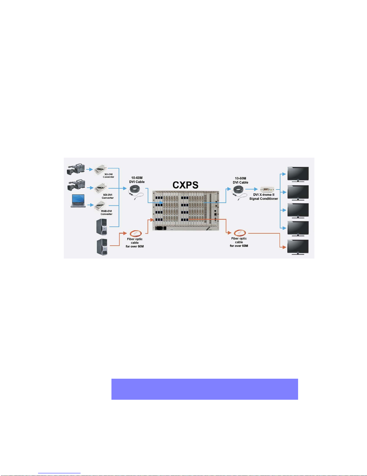
CXPS. See Figure 7, “System Installation Overview Diagram,” on page 27 for an
illustration of a typical CXPS system diagram.
CXPS Manual Edition 1.07 Installation 25
Page 32

INSTALLATION INSTRUCTIONS
Final System Installation
1 Connect any dual-link DVI signals to DVI input connectors on cards in odd-numbered
input slots only.
The DVI input cards in the odd-numbered slots (that is, slots 1, 3, 5, 7, and 9) can accept duallink DVI inputs. See “Dual-Link vs Single-Link” on page 12 for more information about duallink DVI considerations.
2 Connect any single-link DVI or fiber signals to input connectors on any card.
All DVI and fiber input channels can accept single-link inputs.
3 Apply DVI converters to any non-DVI signals and connect to input connectors on any
CXPS DVI input card.
Step 3: Connect CXPS Outputs to All Displays
WHAT YOU WILL NEED FOR THIS STEP
• All DVI or fiber-capable display devices you want to use in your installation
• DVI or fiber cable
• (Optional) DVI signal conditioners. If the distance to the display requires more than
seven meters of DVI cable, a Black Diamond Video DVI X-treme Cable Kit should be
used with the DVI X-treme II Conditioner and appropriate length of cable provided in
the DVI cable kit.
26 Installation Edition 1.07 CXPS Manual
Page 33
INSTALLATION INSTRUCTIONS
Final System Installation
DESCRIPTION
Connect all DVI or fiber-capable displays to the CXPS output channels. See Figure7,
“System Installation Overview Diagram,” on page 27 for an illustration of a typical CXPS
system diagram.
. . . . .
FIGURE 7.
1 Connect DVI (or fiber) cable to first DVI (or fiber) output of the CXPS.
2 Connect the other end of the cable as follows:
a
If the DVI cable is more than seven meters in length, connect it to the input of the DVI
System Installation Overview Diagram
X-treme II Conditioner. Connect a second DVI cable, no more than seven meters in
length, to the DVI display device.
b If the DVI cable is less than seven meters in length, connect it directly to the DVI display
device.
c For cable distances over 60 meters, use fiber cable to connect the CXPS to the display
device.
3 Repeat Steps Step 1 and Step 2 for all other DVI and fiber output channels to be used in
your installation.
NOTE:
CXPS Manual Edition 1.07 Installation 27
Displays capable of accepting dual-link DVI signals should be connected to
output channels located on the DVI cards in odd-numbered slots. See
“Dual-Link vs Single-Link” on page 12 for more information.
Page 34
INSTALLATION INSTRUCTIONS
Final System Installation
Step 4: Establish Permanent Remote Control
WHAT YOU WILL NEED FOR THIS STEP
• Laptop or personal computer
• For RS-232 control: RS-232 direct-connect type serial cable with DB9 (male) connector
• For Ethernet control: Ethernet cable. If you are connecting your control computer
directly to the CXPS, you may need a crossover cable.
• RS-232 and Telnet Commands:
SHOWNET
ipaddr
telnet
DESCRIPTION
When all video sources going into the CXPS and all video outputs going to the displays or
recording devices have been shown to function correctly, permanent con trol of the CXPS
can be established using the RS-232 serial interface, 10/100T Ethernet interface, o r the webserver GUI. Black Diamond Video recommends that you read this section carefully before
establishing permanent controls.
<ipaddr>
<ipaddr> 8998
When connecting a control computer to the RS-232 connector on the CXPS,
IMPORTANT!
you must use a direct-connect type cable.
When connecting a control computer directly to the Ethernet connector you
must use a crossover cable. Both the control computer and the CXPS must
then use a static IP address.
Whether the CXPS is controlled through an RS-232 terminal, a 10/100T Ethernet port using
telnet commands, or the web-server GUI, control begins with the RS-232 terminal. The RS232 terminal is used to check and assign an IP address for the CXPS. Without configuring
network settings, the network and web control will not work.
Details of the serial control commands and telnet protocols are in Appendix A, “RS-232
and 10/100T Protocol.”
Control of the CXPS can be accomplished using any one of the following five methods:
• RS-232 Only—This method is used when only RS-232 control is desired. Controls are
managed using the CXPS command set (Appendix A).
• 10/100 T Ethernet and RS-232—This method is used when 10/100T Ethernet control
of the CXPS is desired and the control computer is a client on a larger network which
uses DHCP (dynamic host configuration protocol) to assign IP addresses. This is the
28 Installation Edition 1.07 CXPS Manual
Page 35

INSTALLATION INSTRUCTIONS
. . . . . . . . . . . . . . .
. . . . . . . . . . . . . . .
Final System Installation
default setting for 10/100T Ethernet control of the CXPS. RS-232 control is used to
determine the dynamic IP address of the CXPS.
• 10/100 T Ethernet Only—This is a simpler method than control by 10/100 T Ethernet
and RS-232, but it requires that a static IP address be assigned to the CXPS and to the
control computer. A static IP address is where a computer uses the same address every
time a user logs on to a network. By default, the CXPS is configured with a dynamic IP
address.
The type of IP address for the control computer depends upon whether the computer is
connected directly to the CXPS Ethernet connector, or if it is connected via a network:
Connection Route IP Address Type
Direct to CXPS Static only
Through a network Dynamic or Static
If the computer controlling the CXPS is a client assigned to a larger network, the
network administrator will need to assign the static IP address to the control computer
and CXPS. If the static IP address of the CXPS is unknown, it can be accessed via the
RS-232 interface using the SHOWNET command. The RS-232 controls must be used for
initial set-up of the CXPS IP address, and thereafter will no longer be required.
. . . . .
• Web-Server GUI and RS-232 Control— This method uses a web-server GUI rather
than Telnet commands to control the CXPS over a network. In this instance, the control
computer is a client on a larger network which uses DHCP to assign IP addresses. The
web-server GUI within the CXPS is invoked by opening a web browser on the control
computer (Black Diamond Video recommends Mozilla Firefox) and entering the IP
address of the CXPS into the address bar of the browser. This will bring you to the GUI
log-in page.
• Web-Server GUI without RS-232 Control—With this method, a “static” IP address is
assigned to the CXPS and the control computer. A web-browser (Black Diamond Video
recommends Mozilla Firefox) is opened and the static IP address of the CXPS is entered
into the address bar of the browser. This is the easiest method for controlling the CXPS.
NOTE: The default password needed to log in to the GUI is blackdiamond.
RS-232 ONLY
1 Connect the control computer to the RS-232 connector on the CXPS using an RS-232
direct-connect type cable.
2 Open up a serial port terminal on the control computer connected to the CXPS.
CXPS Manual Edition 1.07 Installation 29
Page 36

INSTALLATION INSTRUCTIONS
Final System Installation
On Microsoft Windows, you can use HyperTerminal for serial communications.
3 Configure the port settings as follows:
• Baud: 9600
• Data bits: 8
• Parity: None
• Stop bits: 1
• Flow control: None
The RS-232 connection to the CXPS is established and the processor can be controlled using
the RS-232 command set found in Appendix A, “RS-232 and 10/100T Protocol.”
NOTE:
To avoid recreating the connection parameters each time you reestablish
RS-232 connection to the CXPS, you can save the connection for
subsequent hyperterminal sessions.
10/100T ETHERNET AND RS-232
1 Connect the CXPS to your network using the Ethernet connector.
2 Connect the RS-232 control computer to the CXPS with an RS-232 direct-connect type
cable.
3 From the RS-232 control computer, determine the CXPS IP address:
a
Establish RS-232 control of the CXPS as described in “RS-232 Only” on page 29.
b Enter the command: SHOWNET (see Appendix A, “RS-232 and 10/100T Protocol,” for
details).
The CXPS IP address is returned.
4 From the Ethernet control computer, which must be connected to the same network as
the CXPS, open All Programs > Accessories > Command Prompt and enter the
command telnet <IP address> 8998 using the IP address obtained in Step 3.
The Telnet session is initiated.
5 Enter the network password.
The default network password is “blackdiamond”.
Telnet control is established. See
key commands and how they are used to control the CXPS.
Appendix A, “RS-232 and 10/100T Protocol,” for a list of
NOTE:
30 Installation Edition 1.07 CXPS Manual
The RS-232 control computer and the Ethernet control computer can be
the same machine or two different machines.
Page 37

INSTALLATION INSTRUCTIONS
To exit the network connection, enter the command exit.
Final System Installation
. . . . .
NOTE:
10/100T ETHERNET ONLY
1 Connect the control computer directly to the CXPS with an RS-232 direct-connect type
cable and a 10/100T Ethernet crossover cable.
2 Set the static IP address of the CXPS:
Establish RS-232 control of the CXPS as described in “RS-232 Only” on page 29.
a
b Issue the IPADDR command using the static IP address assigned to the CXPS. For
example:
IPADDR 192.168.1.103
The CXPS is assigned the static IP address 192.168.1.103.
3 Set the static IP address of the control computer. If you are using Microsoft Windows,
follow these steps:
Click Start > All Programs > Accessories > Communications > Network Connections.
a
The Network Connections window appears.
b Right-click on Local Area Connection and select Properties.
If the CXPS is powered off for several days, when the equipment is
powered back on, the DHCP server within the network may issue a new IP
address. If this happens, 10/100T Ethernet control can only be restarted by
beginning at Step 3 and determining the new IP address using the RS-232
SHOWNET command again.
c Click on Internet Protocol (TCP/IP) to highlight it and click Properties.
d Select Use the following IP address and enter the static IP address assigned to your
e Click on Subnet mask and the number 255.255.255.0 should appear.
f Enter the static IP address in the Default gateway field.
g Click OK.
CXPS Manual Edition 1.07 Installation 31
The Local Area Connection Properties window appears.
The Internet Protocol (TCP/IP) Properties window appears.
control computer into the IP address field.
For example, enter 192.168.1.10.
For example, enter 192.168.1.1.
Page 38

INSTALLATION INSTRUCTIONS
Final System Installation
The static IP address of the control computer is set.
4 Click Start and navigate to All Programs > Accessories > Command Prompt.
The Command Prompt window appears.
5 Enter the command telnet <IP address> 8998 using the IP address assigned to the
CXPS in Step 2 above.
Telnet control is established. See AppendixA, “RS-232 and 10/100T Protocol,” for a list of
commands and how they are used to control the CXPS.
Because the CXPS now has a static IP address, the RS-232 interface is no longer required. If
the IP address of the CXPS is misplaced, simply reconnect the RS-232 controls and use the
SHOWNET command to retrieve the IP address.
The final system installation process is complete.
WEB-SERVER GUI AND RS-232
1 Download Java software onto the RS-232 control computer:
a
Open your web browser and go to www.java.com.
Download the appropriate version for your operating system.
b Black Diamond Video supports Java Applet versions up to 5.0.
2 (Recommended) Download and inst all the Mozilla Firefox web browser onto the control
computer from www.mozilla.com/firefox/.
3 Connect the control computer directly to the CXPS with an RS-232 direct-connect type
cable and a 10/100T Ethernet crossover cable.
4 From the RS-232 control computer, determine the CXPS IP address:
a
b Enter the command: SHOWNET (see Appendix A, “RS-232 and 10/100T Protocol,” for
The CXPS IP address is returned.
5 Open the Firefox web browser on the control computer and enter the IP address
obtained in Step 4 into the browser address bar.
The GUI is initiated and control of the CXPS is now done through the GUI.
NOTE:
WEB-SERVER GUI ONLY
1 Download Java software onto the RS-232 control computer:
Establish RS-232 control of the CXPS as described in “RS-232 Only” on page 29.
details).
If the CXPS is powered off for several days, when the equipment is
powered back on, the DHCP server within the network may issue a new IP
address. If this happens, web-server GUI control can only be restarted by
beginning at Step 3 and determining the new IP address using the RS-232
SHOWNET command again.
32 Installation Edition 1.07 CXPS Manual
Page 39

INSTALLATION INSTRUCTIONS
Final System Installation
a Open your web browser and go to www.java.com.
b Download the appropriate version for your operating system.
c Black Diamond Video supports Java Applet versions up to 5.0.
2 (Recommended) Download and inst all the Mozilla Firefox web browser onto the control
computer from www.mozilla.com/firefox/.
3 Connect the control computer directly to the CXPS with an RS-232 direct-connect type
cable and a 10/100T Ethernet crossover cable.
. . . . .
NOTE:
4 Set the static IP address of the CXPS:
a
b Issue the IPADDR command. For example:
The RS-232 control computer and the Ethernet control computer can be
the same machine or two different machines.
Establish RS-232 control of the CXPS as described in “RS-232 Only” on page 29.
IPADDR 192.168.1.103
The CXPS is assigned the static IP address 192.168.1.103.
5 Set the static IP address of the control computer. If you are using Microsoft Windows,
follow these steps:
Click Start > All Programs > Accessories > Communications > Network Connections.
a
The Network Connections window appears.
b Right-click on Local Area Connection and select Properties.
The Local Area Connection Properties window appears.
c Click on Internet Protocol (TCP/IP) to highlight it and click Properties.
The Internet Protocol (TCP/IP) Properties window appears.
d Select Use the following IP address and enter the IP addr ess assigned to your CXPS into
the IP address field.
For example, enter 192.168.1.10.
e Click on Subnet mask and the number 255.255.255.0 should appear.
f Enter the static IP address in the Default gateway field.
g Click OK.
CXPS Manual Edition 1.07 Installation 33
For example, enter 192.168.1.1.
Page 40

INSTALLATION INSTRUCTIONS
. . . . . . . . . . . . . . . . . . . . . . . . . . . . . . . . . . . . . . . . . . . . . . . . . . . .
. . . . . . . . . . . . . . . . . . . . . . . . . . . . . . . . . . . . . . . . . . . . . . . . . . . .
System Reset
The static IP address, subnet mask, and IP address gateway of the control computer are
set.
6 Open the Mozilla Firefox web-browser and type the CXPS IP address set in Step 4 into
the address bar of the browser and press Enter.
The GUI will be invoked and control of the CXPS is now done through the GUI. Details of the
web-server GUI controls are in Chapter 7, “Matrix Switching.”
Because the CXPS now has a static IP address, the RS-232 interface is no longer required. If
the IP address of the CXPS is misplaced, simply reconnect the RS-232 controls and use the
SHOWNET command to retrieve the IP address.
SYSTEM RESET
Occasionally, the CXPS CPU may need to be reset. Prior to installing the equipment in its
final position, you can simply power cycle the unit using the power switch on the rear panel.
However, once the unit is installed, it may not be easy to access the rear panel. In this
situation, you can use the RS-232 serial command: RESET.
NOTE:
The system reset mimics a power cycle and does not affect your system
configuration settings, such as matrix routing settings.
CHANGING I/O CARD CONFIGURATION
Input and output cards may be added or removed from the CXPS as needed. The following
is applicable for Firmware versions 4.85 and previous.
After installing a new card:
1 Issue the RESTOREDEFAULT command to restore the factory defaults for user
parameters.
The command syntax is: RFD
2 Issue the command RSTOUTPUTATTR to reset the output gamma, lower, upper,
brightness, and contrast to the default values.
The command syntax is: RSTOUTPUTATTR
NOTE:
34 Installation Edition 1.07 CXPS Manual
If you are installing a USB card in a CXPS that did not previously contain a
USB card, contact Black Diamond Video at (877) 549-6600 for assistance.
Technical support will provide a command to change the product type of
your unit from CXPS to CXPS_USB.
Page 41

. . . . . . . . . . . . . . . . . . . . . . . . . . . . . . . . . . . . . . . . . . . . . . . . . . . .
Create Startup Macro
INSTALLATION INSTRUCTIONS
Startup Macro
STARTUP MACRO
The Startup Macro feature allows the user to set up a list of comm ands that will be exe cuted
automatically by the CXPS after it is powered on, or after a power cycle or interruption.
This feature is available beginning with firmware version 4.85. There are four commands
related to the Startup Macro: CSM, DSM, RSM, and VSM.
These Startup Macro commands are detailed below.
The CSM command creates the Startup Macro. To create the startup Macro:
1 Issue the command: CSM.
2 Enter the commands you would like stored in the Macro, up to 2048 characters.
a
Editing the Macro commands is difficult to do in the terminal program as it is not a text
editor. Therefore, it is suggested that a real text editor be used to create or edit the
Macro. The commands may then be copied and pasted into the command prompt.
. . . . .
Delete Startup Macro
Run Startup Macro
View Startup Mac ro
3 Press Esc.
4 Press carriage return.
The DSM command deletes the Startup Macro. To delete the Startup Macro, issue the
command: DSM.
The RSM command runs the Startup Macro manually. After powering the system on, the
Startup Macro will run automatically. To run the Startup Macro manually, issue the
command: RSM.
The VSM command allows the user to view the comman ds in the S tartup Mac ro. To view the
commands in the Startup Macro, issue the command: VSM.
CXPS Manual Edition 1.07 Installation 35
Page 42

INSTALLATION INSTRUCTIONS
Startup Macro
36 Installation Edition 1.07 CXPS Manual
Page 43

. . . . .
. . . . . . . . . . . . . . . . . . . . . . . . . . . . . . . . . . .
A
. . . . . . . . . . . . . . . . . . . . . . . . . . . . . . . . . . . . . . . . . . . . . . . . . . . .
BOUT THE
W
EB
-S
ERVER
Matrix switching can be handled using the web-server GUI. This chapter describes how to
access the GUI web-server and introduces the GUI’s appearance and function.
More information on using the GUI appears in the following operati onal chapters covering
matrix switching.
ACCESSING THE GUI
GUI
6
NOTE:
The web-server GUI within the CXPS is invoked by opening a web browser on the control
computer (Black Diamond Video recommends Mo zilla Firefox) and entering the IP address
of the CXPS into the address bar of the browser. This will bring you to the GUI log-in page,
shown in Figure 8. Logging in will give you access to the GUI Web Controller page,
“Matrix.”
Log into the GUI by entering your password. The default password associated with your
CXPS is blackdiamond.
Java Applet must be installed prior to opening the web-server GUI. For
instructions, see Chapter 5, “Installation Instructions.”
CXPS Manual Edition 1.07 Operation 37
Page 44

ABOUT THE WEB-SERVER GUI
. . . . . . . . . . . . . . . . . . . . . . . . . . . . . . . . . . . . . . . . . . . . . . . . . . . .
Appearance and Functions of the GUI
FIGURE 8. CXPS GUI Log-In Page
APPEARANCE AND FUNCTIONS OF THE GUI
The GUI Web Controller currently offers one section: Matrix.
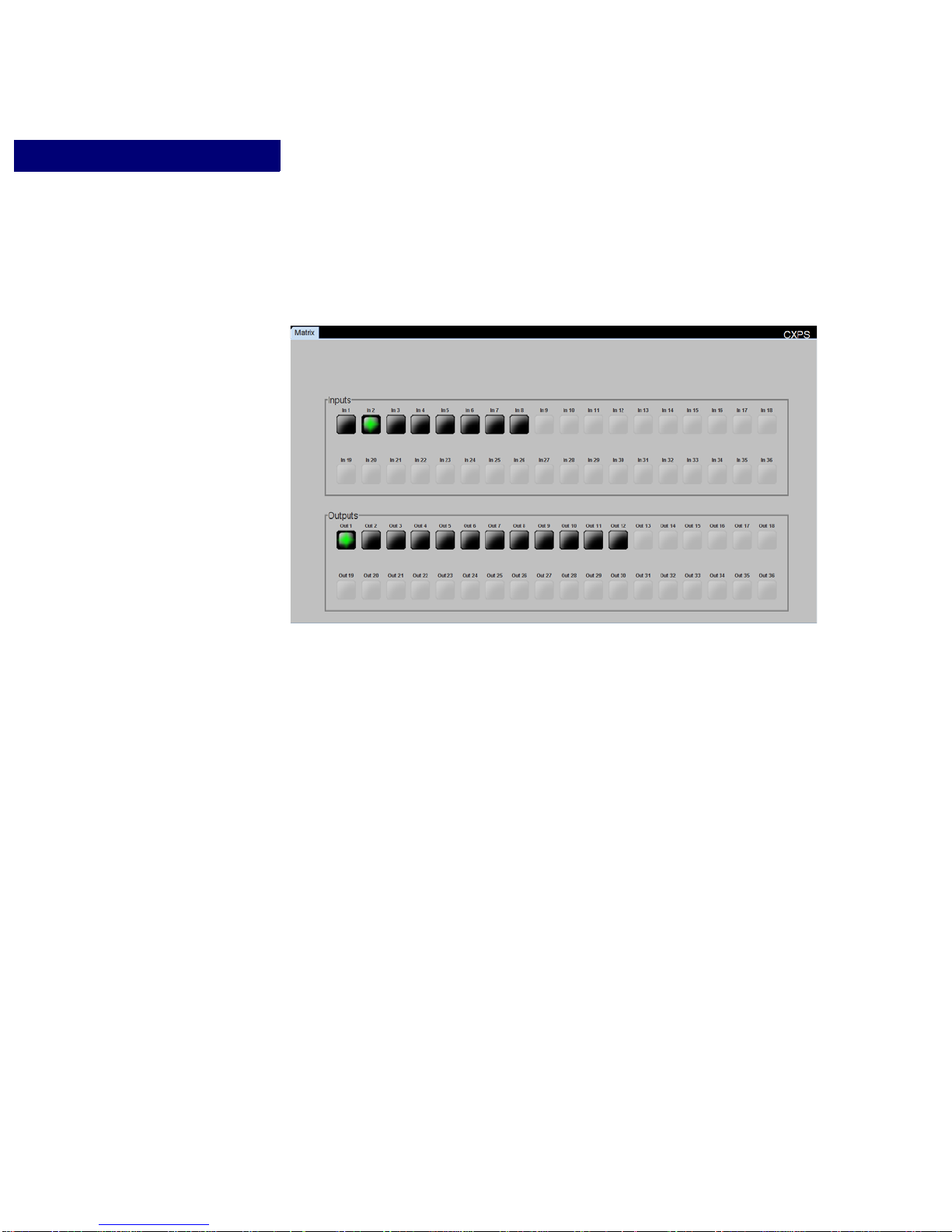
• Matrix—this section allows you to switch between input sources and output displays
using a mouse or touch-panel. The switch section of the GUI reflects only the last inp ut
to be selected and the output sources to which it is currently routed. Their input and
output buttons are illuminated green, indicating that they are connected.
38 Operation Edition 1.07 CXPS Manual
Page 45
ABOUT THE WEB-SERVER GUI
Appearance and Functions of the GUI
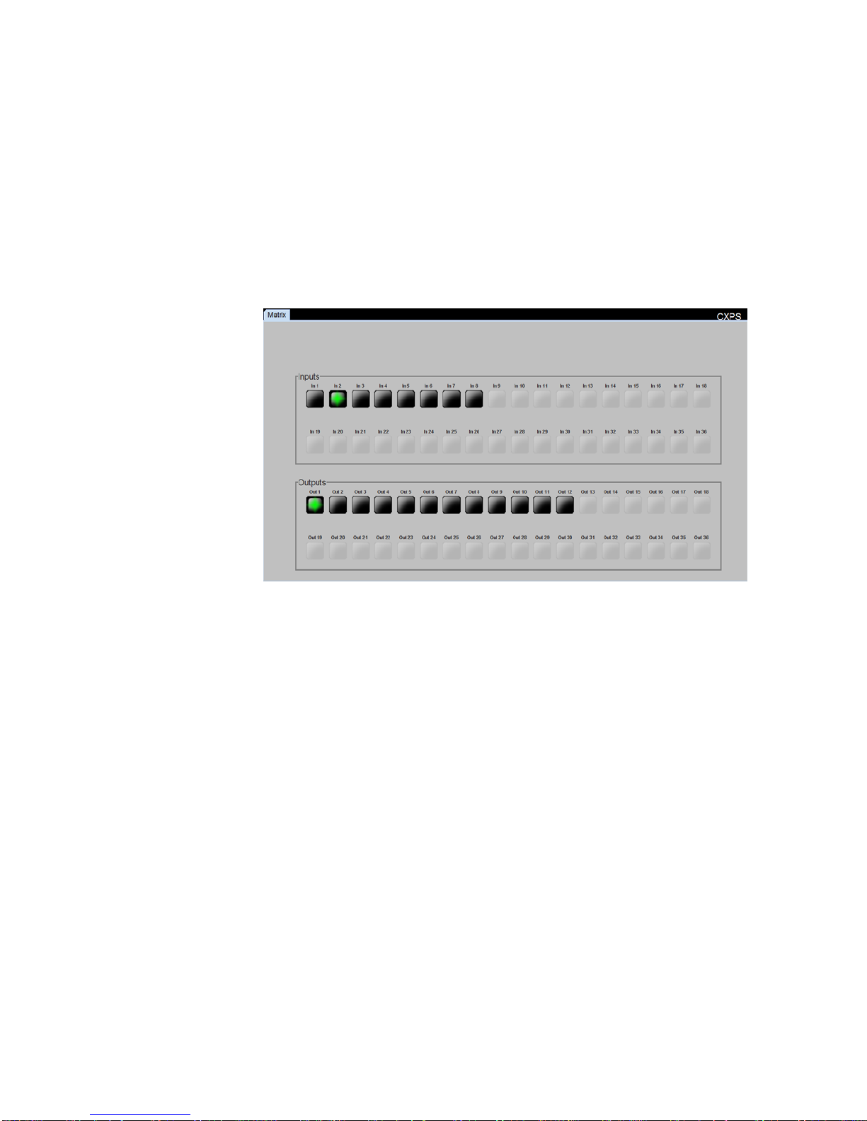
For example, in Figure9, the most-recently selected input is Input 2, shown by the green
Input 2 button. Input 2 is routed to Output 1, indicated by the green Output 1 button.
. . . . .
FIGURE 9. CXPS GUI Matrix Section
For information about switching using the Matrix section of the web-server GUI, see
Chapter 7, “Matrix Switching.”
CXPS Manual Edition 1.07 Operation 39
Page 46

ABOUT THE WEB-SERVER GUI
Appearance and Functions of the GUI
40 Operation Edition 1.07 CXPS Manual
Page 47

. . . . .
. . . . . . . . . . . . . . . . . . . . . . . . . . . . . . . . . . .
M
. . . . . . . . . . . . . . . . . . . . . . . . . . . . . . . . . . . . . . . . . . . . . . . . . . . .
. . . . . . . . . . . . . . . . . . . . . . . . . . . . . . . . . . . . . . . . . . . . . . . . . . . .
ATRIX
S
WITCHING
This chapter describes the matrix switching capabilities of the CXPS.
ABOUT MATRIX SWITCHING
The CXPS provides 36 x 36 DVI matrix switching and is controlled with the web-server
GUI or by using RS-232 or Telnet commands. Any connected input’s channel can be
switched to any output channel.
For information about setting up remote control of your device, see “Step 4: Establish
Permanent Remote Control” on page 28.
MATRIX SWITCHING CONTROL: GUI
The GUI I/O buttons found on the Matrix page of the GUI let you quickly and easily set up
and modify input-output assignments. Figure 10 shows an example of the CXPS GUI being
used to control matrix switching assignments.
7
CXPS Manual Edition 1.07 Operation 41
Page 48
MATRIX SWITCHING
Matrix Switching Control: GUI
FIGURE 10. Matrix-Switching Section of the GUI Web Controller
The dark gray input and output buttons on the GUI represent the inputs and outputs of the
connected CXPS. The GUI for a fully configured CXPS will have 36 input buttons and 36
output buttons.
To switch an input to an output
1 In the Matrix page of the GUI, click on a numbered input button to select the input you
want to switch.
The button will flash green, indicating that it has been selected. You now have 5 seconds to
route it to an output destination.
2 Click the Output button for the output to which you want to route the selected input.
3 The selected input is now routed to the output channel you have just chosen.
Both input and output buttons will be illuminated green to indicate their connection.
EXAMPLE ONE
To route Input 1 to display at Output 6, you firs t select the Input 1 button, and then promptly
select the Output 6 button. This will route Input 1 to Output 6.
42 Operation Edition 1.07 CXPS Manual
Page 49

Matrix-Switching Control: RS-232 and Telnet
. . . . . . . . . . . . . . . . . . . . . . . . . . . . . . . . . . . . . . . . . . . . . . . . . . . .
EXAMPLE TWO
To route Input 1 to display at Outputs 6 and 7, select the Input 1 button, then select the
Output 6 button, routing Input 1 to Output 6. Then, select the Input 1 button again, and
select the Output 7 button, routing Input 1 to Output 7.
To view individual input-output assignments: GUI Matrix Page
Individual input-output assignments can be viewed by pressing the numbered output buttons
found in the Outputs section of the Matrix page. Selecting a numbered output button will
illuminate both the selected button and the input button to which it has been routed.
EXAMPLE
To see what input is routed to Output 1, press the Output 1 button. In our example,
Figure 10, you can see that Input 2 is routed to Output 1, as indicated by the green lights
illuminating their respective buttons.
MATRIX-SWITCHING CONTROL: RS-232 AND
TELNET
MATRIX SWITCHING
. . . . .
Using RS-232/Te lnet commands, you can control input-output assignments, determine
which input is routed to a particular output, and even simultaneously switch input-output
assignments.
By default, the first single-link DVI input is routed to all single-link outputs and the first
dual-link DVI input is routed to all dual-link outputs. Single-link DVI inputs can be
displayed on any output channel, but dual-link DVI inputs can only be displayed on the
output channels on the cards in odd-numbered slots. For more information on this
limitation, see “Dual-Link vs Single-Link” on page 12.
For a complete list of serial control commands, see Appendix A, “RS-232 and 10/100T
Protocol.”
NOTE
The CXPS’ RS-232 and Telnet commands and Telnet protocol are
identical.
Switch Command
The SWITCH command is used to route any input to display on any output channel. The
command is:
SW <input #> <output #>
An input can be routed to multiple outputs, which lets you display the same input image on
multiple displays.
CXPS Manual Edition 1.07 Operation 43
Page 50
MATRIX SWITCHING
. . . . . . . . . . . . . . .
. . . . . . . . . . . . . . . . . . . . . . . . . . . . . . . . . .
Matrix-Switching Control: RS-232 and Telnet
EXAMPLE
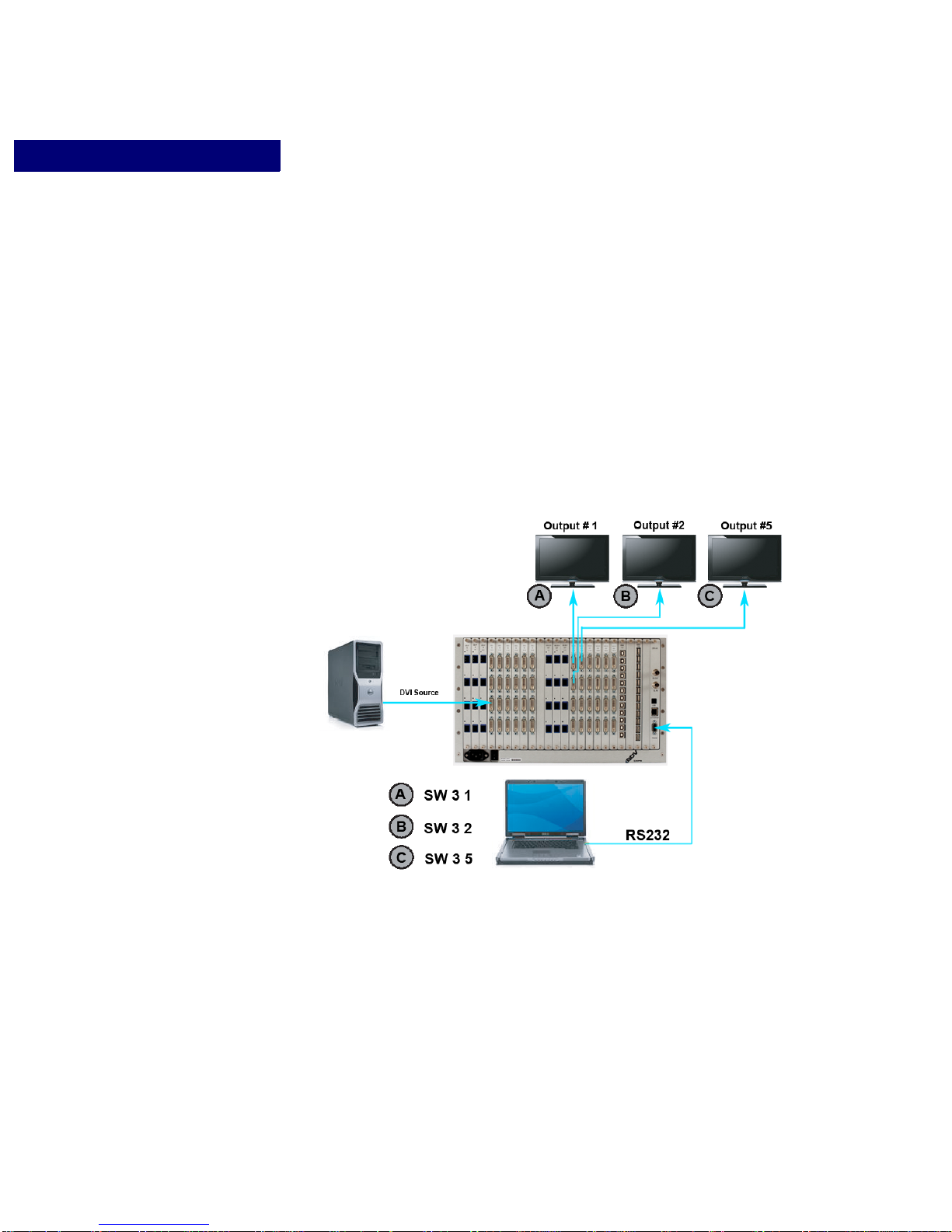
In Figure 11, the switch command is used to route a DVI video source conn ected to Input 3
to three different output channels. If all three commands are issued in succession, the result
is that Input 3 would appear on all three output devices.
Command Action
SW 3 1 Example A—routes Input 3 to Output 1
SW 3 2 Example B—routes Input 3 to Output 2
SW 3 5 Example C—routes Input 3 to Output 5
FIGURE 11. Matrix Switching Example
Output Status Command
The OSTAT command is used to determine which input is set to display on particular
output. The command is:
OSTAT <output #>
44 Operation Edition 1.07 CXPS Manual
Page 51

EXAMPLE
. . . . . . . . . . . . . . .
. . . . . . . . . . . . . . . . . . . . . . . . . . . . . . . . . .
Referring to Figure 11, the OSTAT command would be used as follows:
Command Action
OSTAT 1 Checks the input channel routed to Output 1. Returns
Simultaneous Switching Outputs
Using RS-232/Te lnet Simultaneous Switching Outputs commands, you can change multiple
input-output assignments simultaneously using preset input-output pairs.
The steps required to perform simultaneous matrix switching are listed below.
1. SET INPUT-OUTPUT PAIRS
The Simultaneous Switching Outputs (SSO) command allows the user to store input-output
pairs in ten different preset slots. The maximum number of I/O pairs is equal to the
maximum channels installed.
MATRIX SWITCHING
Matrix-Switching Control: RS-232 and Telnet
. . . . .
input: 3.
To store input-output pairs to a preset slot (numbered 1-10), issue the command:
SSO <preset#> <input> <output> <input> <output> .... <input>
<output>
Where:
• <input> <output> represents an input-output pair.
• <preset #> refers to the preset slot (1-10) to which you would like to store these
switching pairs.
To delete the preset input-output assignments, issue the command:
SSODEL <preset#>
This will erase the I/O pair assignments you had saved to that preset slot.
2. SIMULTANEOUSLY SWITCH OUTPUTS
Once you have assigned input-output pairs to a preset slot number (1-10), you may
simultaneously switch all inputs to display on their specified output.
CXPS Manual Edition 1.07 Operation 45
Page 52

USB Switching
MATRIX SWITCHING
Matrix-Switching Control: RS-232 and Telnet
To simultaneously switch outputs using the preset input-output pairs, issue the command:
SSORUN <preset#>
This will switch each input to display on its paired output, as specified by the pairs you
selected in the previous step.
USB switching is an optional CXPS feature. USB switching may be performed using the
three USB commands below.
USB COMMAND
Change USB switching mode by issuing the command:
USB <mode>
Where <mode> is either “lock” or “free.”
• When in lock mode, USB switching assignments will follow the video switch
assignments. For example, if you issue the video switch command SW 1 2 to route
input 1 to output 2, this would also switch USB 1 to 2.
• When in free mode, USB switching assignments will not follow video switching
assignments, and the user must issue the USBSW command to perform USB switching,
as described below.
USB SWITCH COMMAND
The USB Switch command controls USB switching when under free mode. Use the
command:
USBSW <usb input #> <usb output #>
USB STATUS COMMAND
The USB Status command displays the USB Input/Output connections and also the USB
mode selected.
To view USB status, issue the command: USBSTAT
46 Operation Edition 1.07 CXPS Manual
Page 53

. . . . .
. . . . . . . . . . . . . . . . . . . . . . . . . . . . . . . . . . .
V
. . . . . . . . . . . . . . . . . . . . . . . . . . . . . . . . . . . . . . . . . . . . . . . . . . . .
. . . . . . . . . . . . . . . . . . . . . . . . . . . . . . . . . . . . . . . . . . . . . . . . . . . .
IDEO
S
CALING
8
ABOUT VIDEO SCALING
The CXPS output slots can each be populated with a scaler card- for a maximum of nine
scaler cards possible. A Quad Dual-Link Scaler card (QDLS card) may be used in oddnumbered slots, while a Quad Single-Link Scaler card (QSLS card) may be used in odd or
even numbered slots.
With a scaler card, the output’s image can be scaled up or down or modified to fit a display
resolution different than the native resolution of the input signal. Scaler cards also supply
the CXPS with video windowing, wall processing, and video dissolve capabilities.
The most common scaler operations are discussed below. Scaler operations are performed
using RS-232/ Telnet control.
• For more about configuring the CXPS output channels, see Chapter 3, “Configuration
Options.”
• For information on windowing capabilities, see Chapter 9, “Video Windowing.”
• For information on video dissolve features, see Chapter 10, “Dissolve and Force
Effects.”
• To learn about wall processing capabilities, see Chapter 11, “Wall Processing.”
• For a complete list of RS-232 and Telnet serial control commands, see AppendixA,
“RS-232 and 10/100T Protocol.”
NOTE RS-232 commands and Telnet protocol are identical.
AUTO-RESOLUTION DISPLAY
By default, any input routed through a QDLS card output channel is automatically scaled up
or down to fit the resolution of the connected display device. The original aspect ratio of the
input image is maintained. If this input aspect ratio is different than that of the display
device, black bars will fill areas of unfilled pixels.
Auto-resolution display is an automatic feature of the scaler card and does not need to be
programmed. This feature automatically dete cts the display resolu tion and displays any
input source at its maximum resolution and proper aspect ratio.
CXPS Manual Edition 1.07 Operation 47
Page 54
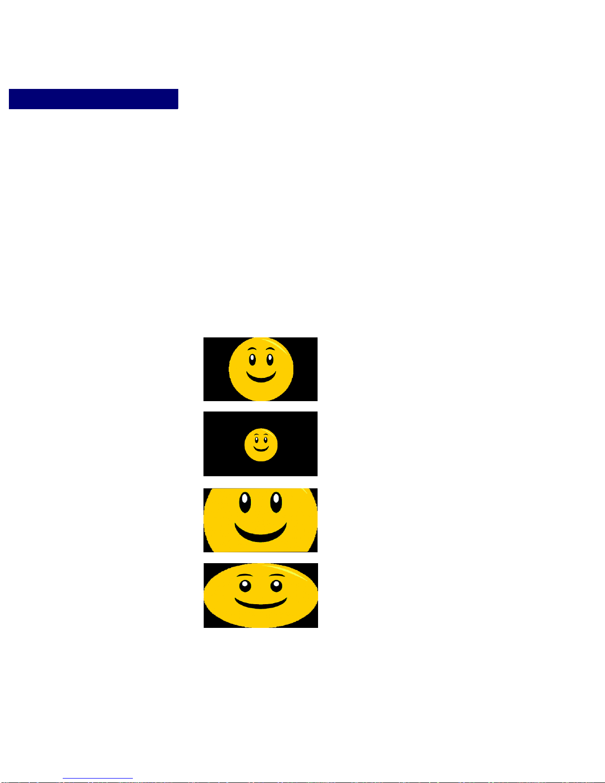
VIDE O SC ALIN G
. . . . . . . . . . . . . . . . . . . . . . . . . . . . . . . . . . . . . . . . . . . . . . . . . . . .
FIT
Full image is displayed with the proper
aspect ratio at the display’s maximum
resolution.
CENTER
Full image is displayed at the image’s
native resolution, with a proper aspect
ratio, and centered on the display.
FILL
Either full vertical or horizontal portion
of the image is displayed, with
remaining portion of the image
cropped. Aspect ratio is maintained.
STRETCH
Image is stretched to fit onto the
display without cropping when the
aspect ratio of the input is different than
that of the display device. The aspect
ratio will not be maintained if the image
is stretched.
Preset Video Positioning
For example, if you have a 1024 x 768 input and you route it through a QDLS output to a
display device operating at 1900 x 1200, the image is automatically scaled up to fill the
screen vertically. Black bands appear on either side of the image in the areas of unfilled
pixels, and the 4:3 aspect ratio is maintained on the output.
PRESET VIDEO POSITIONING
In addition to the default auto-resolution display processing, video going out to a display
device can be positioned in different ways to fit within the display. Figure 12 illustrates the
four most common methods for positioning video within a display.
48 Operation Edition 1.07 CXPS Manual
FIGURE 12. Video Output Positioning Presets
Page 55

VIDEO SCALING
Preset Video Positioning
FIT
FIT scales an image up or down to match a display’s maximum resolution. At the same
time, the proper aspect ratio of the video input is maintained and the entire picture is visible.
The entire output image is “fit” onto the display.
EXAMPLE ONE
To display the 800 x 600 image (4:3 aspect ratio) coming from Output 1 on a
1920 x 1080 display (16:9 aspect ratio) by scaling the image up such that the entire
image is visible, and maintaining its proper 4:3 aspect ratio, use the FIT function.
Vertical black bars will appear on either side of the image in areas of unfilled pixels.
EXAMPLE TWO
To display the 1920 x 1080P image coming from Output 5 on a 1280 x 1024 display
(5:4 aspect ratio) by scaling the image down and maintaining its 16:9 aspect ratio,
use the FIT function. Horizontal black bars will appear above and below the image
in areas of unfilled pixels.
. . . . .
NOTE:
FIT is actually the same as auto-resolution (see “Auto-Resolution Display”
on page 47). You can use the FIT control to return to this default
processing behavior after setting an alternative video position, such as with
the CENTER, FILL, or STRETCH controls, or with a custom setting.
CENTER
CENTER maintains the native resolution of the image a nd centers it within a display that has
a different resolution. The output image is “centered” on the display and surrounded by
black borders in the area of unfilled pixels.
EXAMPLE
To display the 800x 600 image coming from Output 1, at its native resolution,
centered and surrounded by black borders on a 1280 x 1024 display, use the
CENTER function.
FILL
FILL scales an image up or down to match a display’s maximum resolution and also
maintains the proper aspect ratio of the video input. Unlike the FIT mode, however, the
entire image may or may not be displayed. If the input aspect ratio matches the aspect ratio
of the display device, the entire image will appear. However, if the aspect ratios are
different, then one dimension of the image will be cropped.
When scaling up, the image is scaled until it fills the screen both horizontally and ver tically.
With diffe rent aspect ratios, this means that the dimension which required less scaling
CXPS Manual Edition 1.07 Operation 49
Page 56

VIDE O SC ALIN G
Preset Video Positioning
before filling the screen is cropped as scaling continues in order to fill the screen in the other
dimension.
When scaling down, the image is scaled until one dimension fills the screen. At that point,
scaling ceases and the other dimension is cropped.
EXAMPLE
To display the 800 x 600 image (4:3 aspect ratio) coming from Output 1 on a
1920 x 1080 display (16:9 aspect ratio) by scaling the image up and maintaining its
proper 4:3 aspect ratio so that it fills the entire display, use the FILL function.
As more scaling is required to fill the horizontal dimension than the vertical
dimension, the image fills the screen and is cropped vertically on the display.
STRETCH
STRETCH “stretches” an image to fit onto the display without cropping when the aspect
ratio of the input is different than that of the display device. The resulting image may be
horizontally and/or vertically stretched to fit onto the entire display, and thus will not
maintain its original aspect ratio.
EXAMPLE
To display the 800 x 600 image coming from Output 1, stretched to fit a
1280 x 1024 display, use the STRETCH function. The image will be stretched both
horizontally and vertically to fit the display screen.
Video Positioning Control: RS-232/ Telnet
All four of the video positioning methods use the OWS command paired with an argument to
select the positioning method: FIT, CENTER, FILL or STRETCH.
FIT COMMAND
The command is:
OWS <output #> FIT
where <output #> is the number of your chosen output. For example, to scale the image
displayed on Output 1 to “fit” the output’s maximum resolution, while still keeping all of
the image visible, issue the command OWS 1 FIT.
CENTER COMMAND
The command is:
OWS <output #> CENTER
where <output #> is the number of your chosen output. For example, to center the image
displayed on Output 1, issue the command OWS 1 CENTER.
50 Operation Edition 1.07 CXPS Manual
Page 57

VIDEO SCALING
. . . . . . . . . . . . . . . . . . . . . . . . . . . . . . . . . . . . . . . . . . . . . . . . . . . .
. . . . . . . . . . . . . . . . . . . . . . . . . . . . . . . . . . . . . . . . . . . . . . . . . . . .
Custom Vi deo Positioning
FILL COMMAND
The command is:
OWS <output #> FILL
where <output #> is the number of your chosen output. For example, to fill the display on
Output 1, issue the command OWS1FILL.
STRETCH COMMAND
The command is:
OWS <output #> STRETCH
where <output #> is the number of your chosen output. For example, to stretch the image
displayed on Output 1, issue the command OWS 1 STRETCH.
CUSTOM VIDEO POSITIONING
. . . . .
Besides the preset video function of the QDLS card, you can also assign specific horizontal
and vertical dimensions to a video output using RS-232 or Telnet control. With this
function, aspect ratios are not constrained, and, depending on the custom dimensions you
specify, the original aspect ratio may not be preserved.
The command is:
OWS <output #> <hsize> <vsize>
where <hsize> represents a custom number of display pixels and <vsize> represents a
custom number of lines.
EXAMPLE
To display an 800x 600 image from Output 3 as a 1280 x 1024 image size, and not maintain
the original 4:3 aspect ratio, issue the command: OWS 3 1280 1024.
The image is scaled up from 800 x 600 to 1280 x 1024, with a modified aspect ratio of 5:4.
PAN AND ZOOM
The QDLS card output offers both pan and zoom functions. These functions let you focus
on portions of an image and increase and decrease the zoom, and can be engaged using RS232 or Telnet control.
For instructions on panning and zooming in windowing mode, see “Zooming and Panning
Within a Window” on page 71.
CXPS Manual Edition 1.07 Operation 51
Page 58

VIDE O SC ALIN G
i
jl
m
+ <---> -
Pan and Zoom
Pan and Zoom: RS-232/Telnet
When using RS-232 or Te lnet control, you have two types of pan/zoom controls. The first is
a step pan or zoom, where you pan or zoom a percentage each time you issue the command.
The second type of control is a continuous pan or zoom. This type of zoom is meant for use
with a programmable external control device.
PAN
With the PAN command, you can to pan up, down, left, and right at slow or accelerated
speeds.
The command is:
PAN <output #>
When you issue this command, the following field appears to let you control the pan action:
Pan control: i - up, m - down, j - left, l - right q - quit
Each time you press one of these letters, you pan in the selected direction by a set
percentage.
Accelerated pan contro l: use + or -
ZOOM
The standard zoom control lets you step zoom in or out of an image at slow or accelerated
speeds.
The command is:
ZOOM <output #>
52 Operation Edition 1.07 CXPS Manual
Page 59

VIDEO SCALING
. . . . . . . . . . . . . . . . . . . . . . . . . . . . . . . . . . . . . . . . . . . . . . . . . . . .
+ <---> -
a <---> d
Advanced Vi deo Scaling Operations
When you issue this command, the following field appears to let you control the zoom
action:
Zoom control: <+> zoom in, <-> zoom out, <q> quit
Each time you press + or -, you zoom in or out a set percentage.
Accelerated zoom control:
. . . . .
CONTINUOUS PAN & ZOOM
In addition to the standard pan and zoom controls described above, there are special controls
meant for use with a programmable external control device. The continuous pan and zoom
controls lets you continue an action until the STOP command is issued.
For details on continuous pan and zoom controls, see “Continuous Pan & Zoom” on
page 115.
ADVANCED VIDEO SCALING OPERATIONS
This section deals with advanced video scaling operations that are primarily applicable to
custom applications. These scaling operations are employed using RS-232 or T elnet control,
and are listed below:
Genlock
Programmable Look-up Tables
• Match the output timing to the input timing
• Turn off all output scaling
• Customize the red, green, and blue color values
of an output
• Modify one or more color values for custom
effects
CXPS Manual Edition 1.07 Operation 53
Page 60

VIDE O SC ALIN G
Advanced Video Scaling Operations
Genlock
Genlocking video signals is used when you want to synchronize the output timing to the
input timing exactly. The image is passed through to the output without any scaling or
timing shift.
The command is:
GL <output #> <ON|OFF>
EXAMPLE
To genlock the output timing of Output 7 to the input source timing, issue the command:
GL 7 ON.
Programmable Look-Up Tables
The table below shows the four look-up table commands you can employ to customize your
output’s color settings.
WBLUT WBLUT <output #> <value> Changes the output gain for blue channel.
<value> is a value from 0-200.
Default = 100.
WGLUT WGLUT <output #> <value> Changes the output gain for green channel.
<value> is a value from 0-200.
Default = 100.
WLUT WLUT <output #> <value> Changes the output gain for all three color
WRLUT WRLUT <output #> <value> Changes the output gain for red channel.
channels: red, green, and blue.
<value> is a value from 0-200.
Default = 100.
<value> is a value from 0-200.
Default = 100.
54 Operation Edition 1.07 CXPS Manual
Page 61

. . . . .
. . . . . . . . . . . . . . . . . . . . . . . . . . . . . . . . . . .
V
. . . . . . . . . . . . . . . . . . . . . . . . . . . . . . . . . . . . . . . . . . . . . . . . . . . .
IDEO
Overview
W
INDOWING
ABOUT VIDEO WINDOWING
With video windowing, multiple input signals can be displayed on one output display screen
using RS-232/Teln et commands. This is because each window is connected to an output
channel, like an output display would be.
There are two types of windowing modes: standard windowing mode, which can create up
to four windows in total, and picture-in-picture mode, which creates two windows. All
windows can be individually positioned, scaled up or down, and cropped. Each window’s
image can also be panned, zoomed, fit, filled, centered, and stretched to suit your needs.
9
NOTE:
This chapter is applicable to CXPS firmware version 4.00 and above.
CXPS Manual Edition 1.07 Operation 55
Page 62
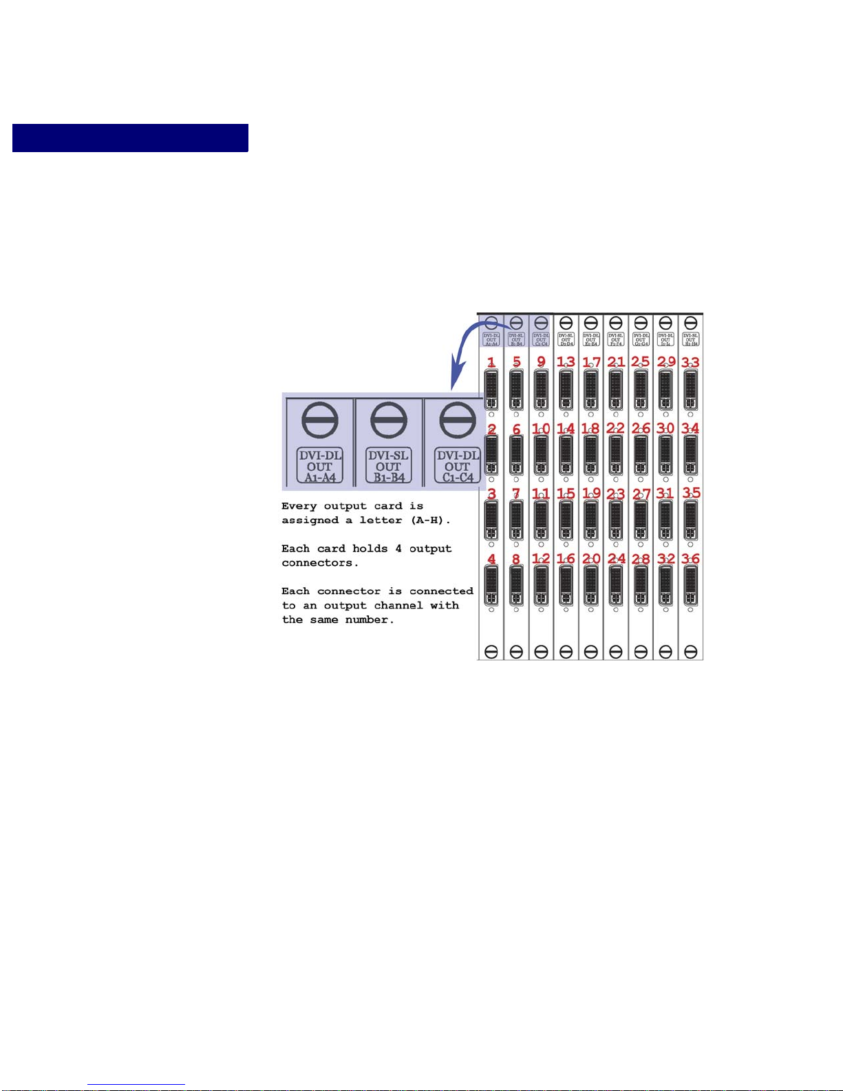
VIDEO WINDOWING
About Vi deo Windowing
CXPS Windowing Capabilities
It is useful to consider the CXPS output connector arrangement, Figure13, when describing
CXPS windowing capabilities.
FIGURE 13. CXPS Output Connector Arrangement
The CXPS can be configured with up to 9 output cards (A through H), and each of those
cards has 4 output channels.
When a window is created, it is also connected to an output channel, just like an output
display would be, for a maximum of 9 sets of 4 windows. Issuing a command that will affect
an output channel, such as a change in matrix switching assignment, will alter the video on
any output display or window connected to that channel.
A window may only be created on an output channel that is on the same card as the channel
connected to the output display screen. For example, output display 9 would be connected to
output channel 9, which appears in card C in Figure 13. Any windows you create on output
display 9 must be on channels also in card C, channels 9 through 12, for a maximum of 4
56 Operation Edition 1.07 CXPS Manual
Page 63

VIDEO WINDOWING
. . . . . . . . . . . . . . . . . . . . . . . . . . . . . . . . . . . . . . . . . . . . . . . . . . . .
Output Timing Synchronization
windows possible in standard windowing mode, and two windows in picture-in-picture
mode.
. . . . .
NOTE:
OUTPUT TIMING SYNCHRONIZATION
Overview
Before standard windowing function or picture-in-picture mode is enabled, the timings of
each output channel that will contain a window must be synchronized to the timing of the
windowing display.
NOTE:
Setting the Output Timing
Y ou may set the output timing of the windowing display, if desired, and then synchronize all
other outputs to this new timing. If you are satisfied with the current output timing of the
windowing display , proceed to the next section, “Synchronizing Output Timings” on
page 58.
To change the video input routed to a window, perform the same steps as
when routing an input to a normal output display screen, as described in
Chapter 7, “Matrix Switching.”
Output timing synchronization must be performed manually when using
RS-232/Telnet control.
STEP 1: THE HOSTLIST COMMAND
Use the Hostlist command to find the number that represents the resolution you
would like your windowing display to use.
CXPS Manual Edition 1.07 Operation 57
To display the h ost table, use the HOSTLIST command, which will produce a list
of output timings for each display’s resolution. Find the resolution you would like
your windowing display to use, and use the corresponding number with the
SETOT command in the next step.
STEP 2: THE SETOT COMMAND
Use the Set Output Timing command to set the output timing of the channel
connected to your windowing display.
The command is:
SETOT <display output #> <host>
Where:
Page 64

VIDEO WINDOWING
Output Timing Synchronization
Synchronizing Output Timings
Before windowing function is enabled, the timing of each output connected to a window
must be synchronized to the timing of the windowing display using the Framesync or
GFramesync command.
You may use the Framesync command to synchro nize the output timing of channels that are
not in a continual numerical range. Alternatively, use the GFramesync command to
sychronize channels in a range.
THE FRAMESYNC COMMAND
Use the Framesync command to specify every output you would like to synchronize to the
windowing display. The command is:
•<display output #> is the output channel number connected to the
windowing display.
•<host> is a number from the host table that represents the output timing of the
you would like the windowing display to use (see Step 1 for help finding this
number).
FRAMESYNC <display output #> <slave1>...<slave3>
Where:
• <display output #> is the number of the output channel connected to the windowing
display.
• <slave1>...<slave3> are the numbers of the output channels other than <m aster> that a re
connected to windows.
• Example: You would like to create 3 windows on your display. The windowing display
is connected to Output 4 and your windows will occupy output channels 1, 2 and 4. You
will first need to synchronize outputs 1 and 2 to the timing of output 4. The command
would be: FRAMESYNC 4 1 2
THE GFRAMESYNC COMMAND
You may use the GFRAMESYNC command if you would like to specify a range of
channels to synchronize to the windowing display. This range must begin with the
windowing display and end with the last output channel connected to a window. The
command is:
GFRAMESYNC <first output> <last output>
Where:
• <first output> is the number of the output channel connected to the windowing display.
58 Operation Edition 1.07 CXPS Manual
Page 65

VIDEO WINDOWING
. . . . . . . . . . . . . . . . . . . . . . . . . . . . . . . . . . . . . . . . . . . . . . . . . . . .
Standard Window Function
• <last output> is the number of the last channel in the range of output channels you would
like to synchronize to <first output>.
• Example: You would like t do create 3 windows on your display. The windowing
display is connected to Output 2 and your windows will occupy output channels 2, 3, and
4. You will first need to synchronize outputs 3 and 4 to the timing of output 2. The
command would be: GFRAMESYNC 2 4
STANDARD WINDOW FUNCTION
Windowing function can be turned on or off at a chosen output. When turning window
function on, the user can select different configurations of windows to display on a
composite output, with a total of four windows possible.
As mentioned previously, a window may only be created on an output channel that is on the
same card as the channel connected to the output display screen. For example, output
display 9 is connected to output channel 9, which appears in card C in Figure 13. Any
windows you create on output display 9 can be created on channels 9 through 12- a
maximum of four windows possible.
. . . . .
NOTE:
Before enabling window function, the timing of each output channel
that will contain a window must be synchronized to the first output
channel on that card. See “Output Timing Synchronization” on page 57
for instructions.
Standard Window Function: RS-232/Telnet
TO ENABLE WINDOW FUNCTION
To turn windowing function on, issue the command:
WINON <display output #> <window #> <window #> <window #>
<window #>
Where:
• <display output #> is the number of the output displaying the windows.
CXPS Manual Edition 1.07 Operation 59
Page 66

VIDEO WINDOWING
. . . . . . . . . . . . . . . . . . . . . . . . . . . . . . . . . . . . . . . . . . . . . . . . . . . .
Picture-In-Picture
• <window #> is the number of the output channel you would like to use under
windowing mode.
NOTE:
• The sequence of the <window #> entries determines the initial priority of those
TO DISABLE WINDOW FUNCTION
To turn windowing function off, issue the command
WINOFF <display output #>
You may only select ou tput channels that are in the same card as the
composite output’s channel, as described in the “About Video
Windowing” section and in Figure 13 on page 56.
windows.
EXAMPLE
You would like to create four windows on output display 9, one window each on
output channels 9, 10, 11, and 12. You would like window 12 to have priority 1,
window 10 to have priority 2, window 11 to have priority 3, and window 9 to have
priority 4.
The command is: WINON 9 12 10 11 9
PICTURE-IN-PICTURE
Picture-in-picture is a special windowing mode that can be controlled via RS-232/Telnet
commands. When picture-in-picture mode is on, one output will fill the entire background,
and another output will be an inset window in the middle of the foreground, as shown in
Figure 14.
NOTE:
To turn pictur e-in-picture mode on, issue the command:
PIPON <display output #> <foreground> <background>
Where:
• <display output #> is the number of the output displaying the windows.
60 Operation Edition 1.07 CXPS Manual
Before enabling picture-in-picture mode, the timing of each output
channel that will contain a window must be synchronized to the first
output channel on that card. See “Output Timing Synchronization” on
page 57 for instructions.
Page 67

VIDEO WINDOWING
Picture-In-Picture
• <foreground> is the number of the output that will be displayed as a window in the
center of the foreground
• <background> is the number of the output that will be displayed as a window that
fills the background, behind the window in the foreground.
To turn off picture-in-picture mode, use the command:
PIPOFF <display output #>
EXAMPLE
Suppose you want to enable picture-in-picture function on output display 1. You would like
a window on output channel 2 to appear in the foreground, and a window on channel 3 to act
as the background. The command would be:
PIPON 1 2 3
. . . . .
FIGURE 14. Picture-in-Picture Mode
CXPS Manual Edition 1.07 Operation 61
Page 68

. . . . . . . . . . . . . . . . . . . . . . . . . . . . . . . . . . . . . . . . . . . . . . . . . . . .
Window On/Off
. . . . . . . . . . . . . . . . . . . . . . . . . . . . . . . . . . . . . . . . . . . . . . . . . . . .
. . . . . . . . . . . . . . . . . . . . . . . . . . . . . . . . . . . . . . . . . . . . . . . . . . . .
VIDEO WINDOWING
Turning a Window On/Off
TURNING A WINDOW ON/OFF
Using an RS-232/Telnet Window command, you can turn an individual window on or off,
without affecting other windows.
To turn a window on or off, issue the command:
WIN <display output #> <window #> <ON|OFF>
Where:
• <display output #> is the number of the output displaying the windows.
• <window #> is the number of the window (1-36) you would like to control.
WINDOW IDENTITY
Window Identity
The Window Identity RS-232/Telnet command identifies the window belonging to a
selected output channel, and provides the window’s position and size.
After issuing the command, the selected window will be on top of other windows on the
display screen, and will blink for 5 seconds. On the command line, the position and size of
the selected window is returned.
To learn a window’s identity, issue the command:
WINID <display output #> <window #>
Where:
• <display output #> is the number of the output displaying the windows.
• <window #> is the number of the output channel whose corresponding window you
wish to identify
WINDOW PRIORITY
Window priority controls the order in which you would like your windows arranged on the
output display screen; each window has its own priority . For example, if your display screen
62 Operation Edition 1.07 CXPS Manual
Page 69
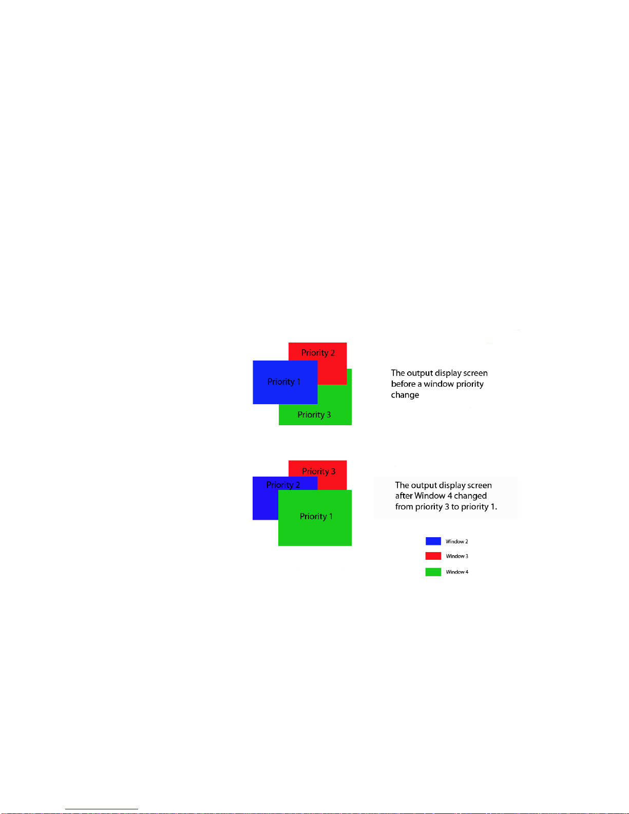
VIDEO WINDOWING
Window Priority
houses a total of four windows, these windows would have numbered priorities 1 through 4,
depending on their order.
The window priority control is useful when windows overlap on the display screen.Window
Priority 1 is the foremost window location on the display screen. Setting any window to
Priority 1 will bring it to the foreground, on top of any windows it was previously behind.
Window Priority 2 is the window position second from the front; setting any window to
Priority 2 will bring it to the front of every other window but the window set to Priority 1. In
following, Window Priority 3 is the window position third from the front, and Window
Priority 4 is the position fourth from the front.
An example of the effects of the window priority feature can be seen in Figure 15.
. . . . .
FIGURE 15. Window Priority Example
Window Priority:
To change an output’s window priority using RS-232/Telnet commands, issue the
command:
CXPS Manual Edition 1.07 Operation 63
Page 70

VIDEO WINDOWING
. . . . . . . . . . . . . . . . . . . . . . . . . . . . . . . . . . . . . . . . . . . . . . . . . . . .
Window Position and Size
WINPRI <display output #> <window #> <priority>
Where:
• <display output #> is the number of the output displaying the windows.
• <window #> is the number of the window (1-36) you would like to control.
• <priority> is the priority number you would like to assign to the chosen output.
WINDOW POSITION AND SIZE
The position of each window on the output display can be independently manipulated using
RS-232 or Teln et commands.
Window Position and Size
TO CONTROL WINDOW POSITION AND SIZE INTERACTIVELY
With the Window Position command, you are able to interactively control the positioning
and size of the window for the selected output.
To control window position and size, issue the command
WINPOS <window #>
A control field will appear that will allow you to interactively position and size the window
to suit your needs.
TO CONTROL WINDOW POSITION AND SIZE USING EXACT
VALUES
With multiple arguments, the window is positioned at the specified location and size.
Issue the command:
WINPOS <window #> <hpos> <vpos> <hsize> <vsize>
Where:
• <window #> is the number of the window (1-36) you would like to control.
• <hpos> and <vpos> refer to the upper left corner of the window.
• <hsize> is in pixels.
• <vsize> is in lines.
64 Operation Edition 1.07 CXPS Manual
Page 71

VIDEO WINDOWING
Window Position and Size
TO ADJUST WINDOW ALIGNMENT
Using the window position alignment commands, you can adjust the position of the window
while maintaining its size. You may center the window in the middle of the windowing
output display, or you may adjust left, right, top, or bottom window alignment to move the
selected window to the edge of the display screen in the selected direction.
To adjust the window’s position on the composite output screen, issue the command:
WINPOS <window #> <LA | RA | TA | BA | CA>
Where:
• <window #> is the number of the window (1-36) you would like to control.
• <LA> is left align
• <RA> is right align
• <TA> is top align
• <BA> is bottom align
. . . . .
• <CA> is center align.
CONTINUOUS WINDOW POSITION & ZOOM
In addition to the standard window position controls described above, there are special
controls meant for use with a programmable external control device. The continuous
position and zoom controls lets you continue an action until the STOP command is issued.
For details on continuous window position and zoom controls, see “Continuous Window
Position & Zoom” on page 116.
WINDOW DUALVIEW FORMATION
The DualView command can be used to arrange a maximum of two windows. This
command sizes each window as closely to one half the size of the output display screen as
possible, positioning one on the left and one on the right according to the priorities assigned
to them when window function was enabled. Any portion of the window that cannot fit
completely into one half of the display screen will extend out of view.
NOTE:
In dualview arrangement, the window assigned priority 1 will appear on the left half of the
screen, and the window assigned priority 2 will appear on the right half of the display
screen. An example of dualview formation can be seen in Figure 16. The shaded areas
Using a dual-link scaler card will allow windows to be downscaled 2:1.
When in dualview formation, it is necessary for some windows to extend
past the boundaries of the screen ONLY when using a single-link scaler
card.
CXPS Manual Edition 1.07 Operation 65
Page 72
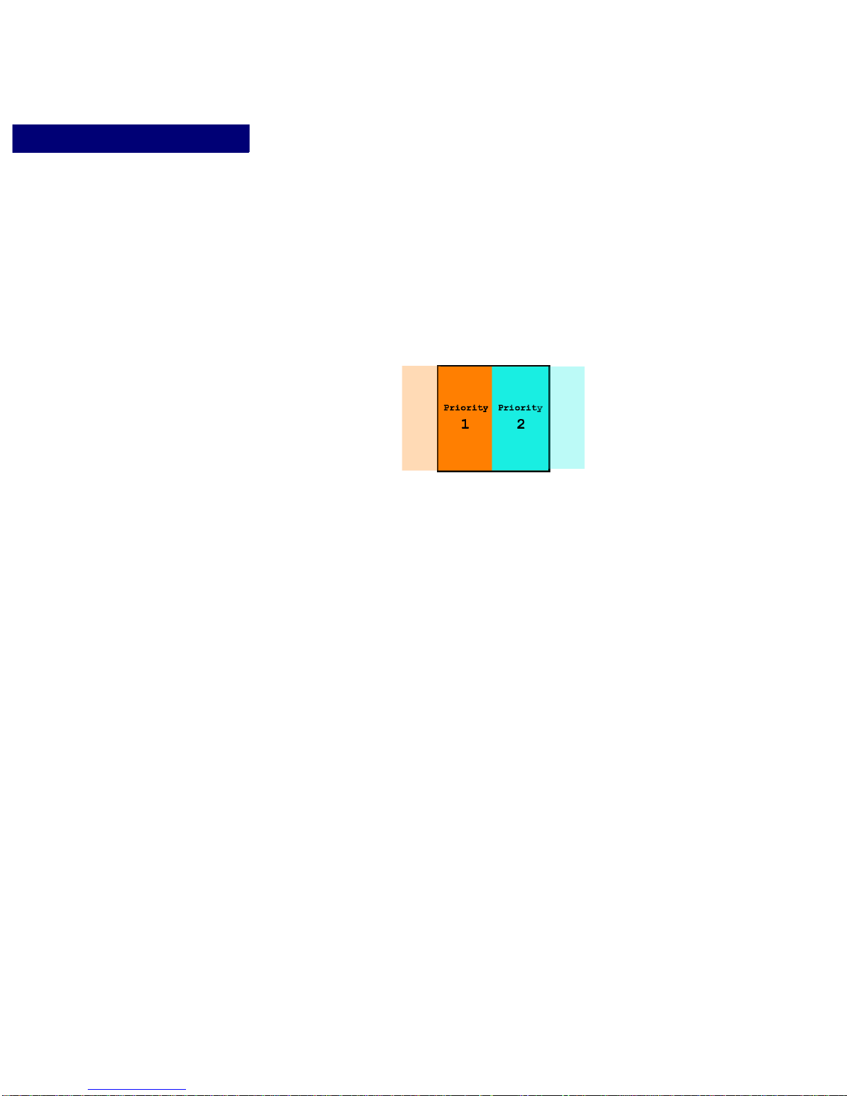
VIDEO WINDOWING
Window Position and Size
represent the portions of the windows that might extend past the display screen when using
a single-link scaler card.
FIGURE 16. An output display containing windows in dualview formatio n
To arrange windows in dualview forma tion, issue the command:
DV <display output #>
Where:
• <display output #> is the number of the output displaying the windows.
Switching in DualView Formation
Switching an input to a window in dualview formation will resize the window to
fit as closely as possible within the half of the screen assigned to that window.
This means that the window may expand or shrink to fit into its area, with any
remaining portions of the window extending off the screen.
Once a window is moved or zoomed, it is no longer in dualview formation. This
means that switching an input to a window that has been repositioned or zoomed
will fill that window with the chosen input’s video. When using a single-link
scaler card, this may require the window to expand to fit the size of the new
input’s video.
66 Operation Edition 1.07 CXPS Manual
Page 73
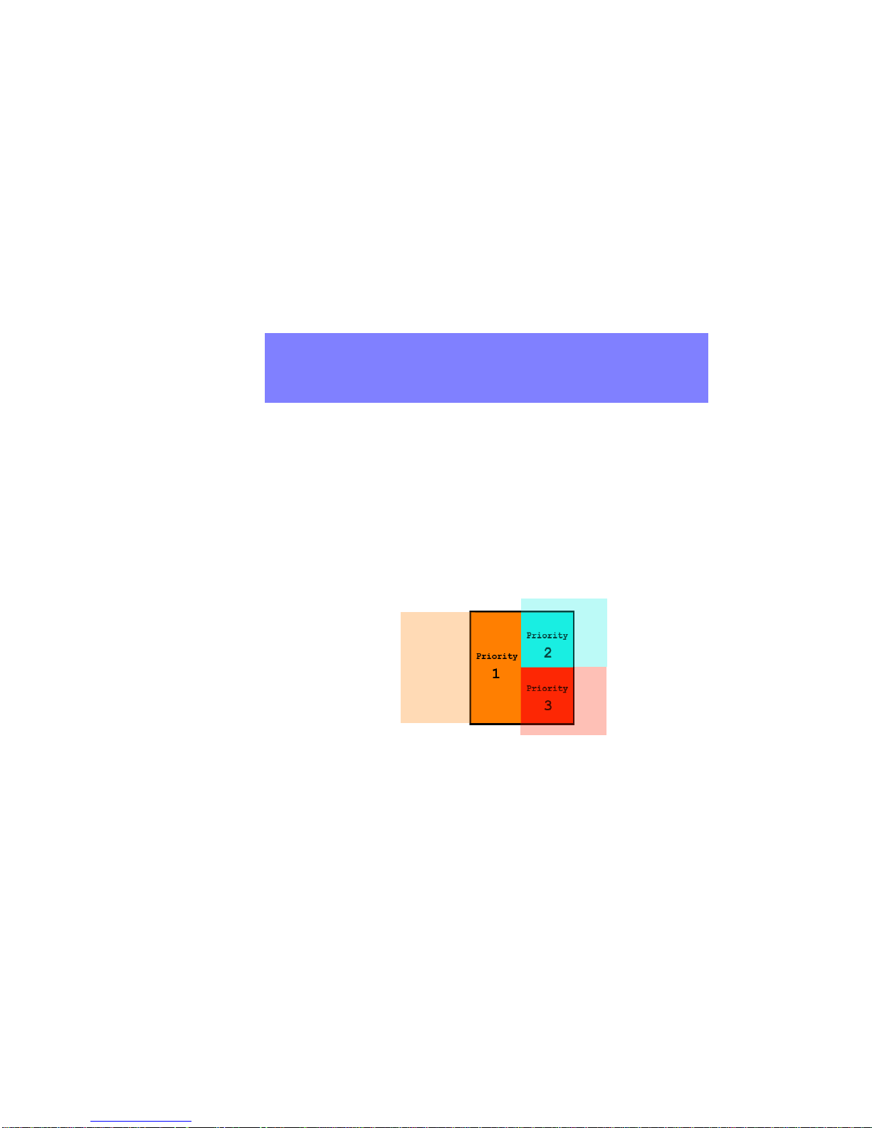
VIDEO WINDOWING
Window Position and Size
WINDOW TRIVIEW FORMATION
The TriView command can be used to arrange a maximum of three windows. This
command arranges them into triview formation according to the priorities assigned to them
when window function was enabled.
. . . . .
NOTE:
In triview, the window assigned priority 1 will appear on the left half of the screen. The
windows assigned priorities 2 and 3 will appear on the right half of the display screen, with
the window holding priority 2 appearing on top of the window with priority 3. An example
of triview formation can be seen in Figure 17. The lightly-colored areas represent the
portions of the windows that might extend past the display screen when using a single-link
scaler card.
Using a dual-link scaler card will allow windows to be sized down to
approximately the size of a postage stamp. When in triview formation, it
is necessary for some windows to extend past the boundaries of the
screen ONLY when using a single-link scaler card.
FIGURE 17. An output display containing windows in triview formation
To arrange windows in triview formation, issue the command:
TV <display output #>
Where:
• <display output #> is the number of the output displaying the windows.
CXPS Manual Edition 1.07 Operation 67
Switching in Tr iView Formation
Page 74
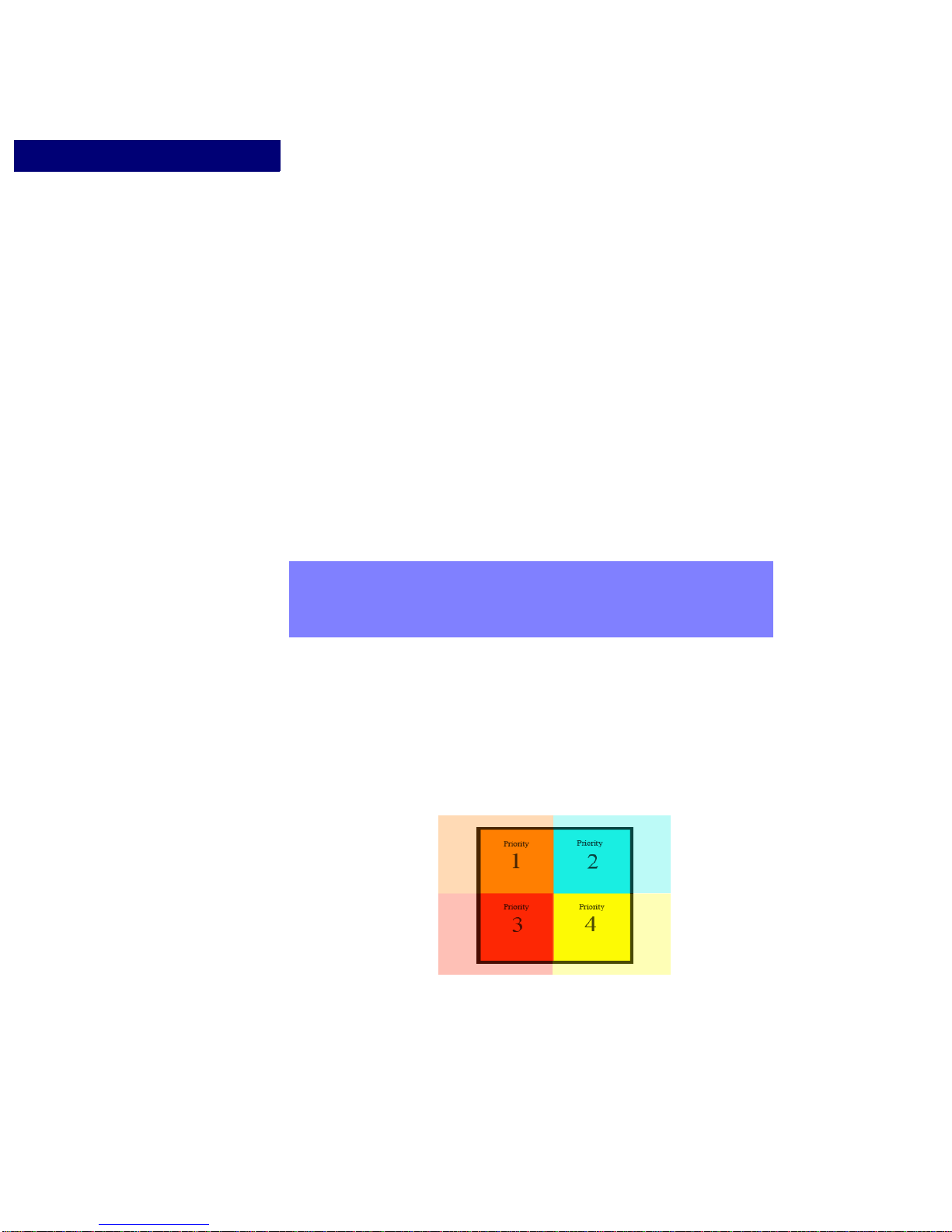
VIDEO WINDOWING
Window Position and Size
Switching an input to a window in triview formation will resize the window to fit
as closely as possible within the portion of the screen assigned to that window.
This means that the window may expand or shrink to fit into its area, with any
remaining portions of the window extending off the screen.
Once a window is moved or zoomed, it is no longer in triview formation. This
means that switching an input to a window that has been repositioned or zoomed
will fill that window with the chosen input’s video. When using a single-link
scaler card, this may require the window to expand to fit the size of the new
input’s video.
WINDOW QUAD FORMATION
The Quadsplit command can be used to arrange a maximum of four windows. This
command sizes each window to fit as closely to one quarter the size of the output display
screen as possible.
NOTE:
Using a dual-link scaler card will allow windows to be sized down to
approximately the size of a postage stamp. When in quad formation, it is
necessary for some windows to extend past the boundaries of the screen
ONLY when using a single-link scaler card.
The windows are arranged in quad formation according to the priorities assigned to them
when window function was enabled. An example of quad formation can be seen below, in
Figure 18. The lightly-colored areas represent the portions of the windows that might
extend past the display screen when using a single-link scaler card.
FIGURE 18. An output display containing wi ndows in quad formation
68 Operation Edition 1.07 CXPS Manual
Page 75

VIDEO WINDOWING
Window Position and Size
To arrange windows in quad for mat ion, issue the command:
QS <display output #>
Where:
• <display output #> is the number of the output displaying the windows.
Switching in Quad Formation
Switching an input to a window in quad formation will resize the window to fit as
closely as possible within the 1/4 of the screen assigned to that window. This
means that the window may expand or shrink to fit into its area, with any
remaining portions of the window extending off the screen.
Once a window is moved or zoomed, it is no longer in quad formation. This
means that switching an input to a window that has been repositioned or zoomed
will fill that window with the chosen input’s video. When using a single-link
scaler card, this may require the window to expand to fit the size of the new
input’s video.
. . . . .
WINDOW CASCADE FORMATION
Use the Cascade command to arrange windows in cascade formation. When in cascade
formation, the windows become equally sized and positioned in an overlapping
arrangement that cascades diagonally across the display. These wind ows are o rganized in
descending order (4,3,2,1) from left to right, according to their priorities, with the window
assigned to priority 1 appearing in the forefront.
To arrange the windows in cascade formation, issue the command:
CC <display output #>
Where:
• <display output #> is the number of the output displaying the windows.
FULL SCREEN WINDOWING
The Window Full Screen command will expand the selected window to fill the entire
display screen.
To fill the composite display screen with the selected window, issue the command:
WINFS <display output #> <window #>
Where:
CXPS Manual Edition 1.07 Operation 69
Page 76

VIDEO WINDOWING
Window Position and Size
• <display output #> is the number of the output displaying the windows.
• <window #> is the number of the window (1-36) you would like to control
WINDOW VIDEO POSITIONING PRESET TOOLS
Each individual window’s disp layed image may be indepen dently manipulated via RS232/Telnet Input Window Size command. These commands apply preset video positioning
to the specified output channel
.
NOTE:
This command will affect window size and position.
To implemen t a preset video position, issue the command:
OWS <window #> <FIT|FILL|CENTER|STRETCH>
The effects of the four window video positioning preset tools are described below. For a
more detailed description of the preset fit, fill, center, and stretch tools, see Chapter 8,
“Video Scaling.”
FIT
<FIT> fits the entire window onto the display, maintaining the original aspect
ration. Equivalent to resetting the video scaling to the default auto-resolution
display.
FILL
<FILL> scales a window up or down to fill the display, maintaining proper
aspect ratio of the input. Image will be cropped if the input and output aspect
ratios do not match
CENTER
<CENTER> maintains native resolution of the input and centers the selected
window within a display.
70 Operation Edition 1.07 CXPS Manual
STRETCH
<STRETCH> stretches a window to fit onto the display without cropping when
the aspect ratio of the input is differen t than th at of the d isplay devi ce. T he as pect
ratio will not be maintained if the image is stretched.
Page 77

. . . . . . . . . . . . . . . . . . . . . . . . . . . . . . . . . . . . . . . . . . . . . . . . . . . .
Pan and Zoom
+ <---> -
VIDEO WINDOWING
Zooming and Panning Within a Window
. . . . .
ZOOMING AND PANNING WITHIN A WINDOW
The QDLS card output offers both pan and zoom functions. These functions let you focus
on portions of an image and increase and decrease the zoom, and can be engaged using RS232 or Telnet control.
When using RS-232 or Te lnet control, you have two types of pan/zoom controls. The first is
a step pan or zoom, where you pan or zoom a percentage each time you issue the command.
The second type of control is a continuous pan or zoom. This type of zoom is meant for use
with a programmable external control device.
ZOOM
The WINZM Command
The standard winzm control lets you step zoom in or out within a selected
window.
The command is:
WINZM <window #>
Where:
•<window #> is the number of the window (1-36) you would like to control.
When you issue this command, the following field appears to let you control the
zoom action:
Zoom control: <+> zoom in, <-> zoom out, <q> quit
Each time you press + or -, you zoom in or out a set percentage.
The ZOOM Command
With the Zoom command, you are able to interactively control the size of the
window for the selected output. Once the window is large enough to completely
fill the display screen, the interactive Z oom command’s pan controls may be used
to pan within the window.
ZOOM <window #>
CXPS Manual Edition 1.07 Operation 71
Page 78

VIDEO WINDOWING
i
jl
m
Zooming and Panning Within a Window
A control field will appear that will allow you to interactively size the window to
suit your needs and then pan within that window once it is as large as the entire
display screen.
•Zooming in will enlarge the window.
•Zooming out will shrink the window.
PAN
With the PAN command, you can pan up, down, left, and right within a selected window.
NOTE:
You must zoom into a window before panning.
The command is:
PAN <window #>
Where
• <window #> is the number of the window (1-36) you would like to control.
When you issue this command, the following field appears to let you control the pan action:
Pan control: i - up, m - down, j - left, l - right q - quit
Each time you press one of these letters, you pan in the selected direction by a set
percentage.
CONTINUOUS PAN & ZOOM
In addition to the standard pan and zoom controls described above, there are special controls
meant for use with a programmable external control device. The continuous pan and zoom
controls let you continue an action until the STOP command is issued.
For details, see “Continuous Panning and Zooming a Window” on page115, and
“Continuous Window Position & Zoom” on page 116.
72 Operation Edition 1.07 CXPS Manual
Page 79
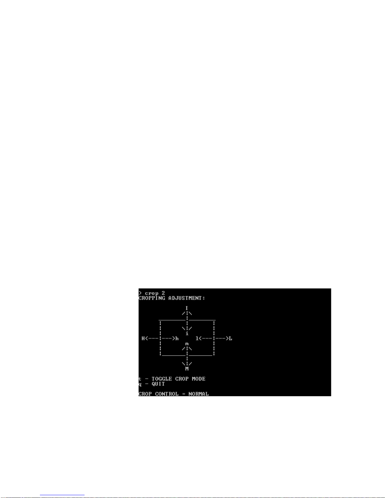
. . . . . . . . . . . . . . . . . . . . . . . . . . . . . . . . . . . . . . . . . . . . . . . . . . . .
Cropping Interactively
VIDEO WINDOWING
Cropping
. . . . .
CROPPING
By issuing the RS-232/Telnet CROP commands, areas of a window may be interactively
cropped, or cropped at a specific location and size. Cropping a window will replace the
removed portion with background.
The three steps involved in interactively cropping a window are listed below.
1. SELECT A WINDOW TO CONTROL
In order to crop a window, you must first select a window to control.
To select a window to crop, issue the command:
CROP <window #>
Where:
• <window #> is the number of the window (1-36) you would like to control.
After entering this command, the Crop control field will appear, as seen in Figure 19. You
may then use this field to control the window you have selected.
FIGURE 19. The Crop Control Field
CXPS Manual Edition 1.07 Operation 73
Page 80

VIDEO WINDOWING
Cropping
2. CHOOSE “CROP”
You must choose to crop the selected window using the Toggle Crop Mode key, the lowercase “t” key.
Pressing this key will change the Crop Control setting at the bottom of the control field to
read “Normal” (as in Figure 19) or “Crop.” If Crop Control is set to “Normal,” no cropping
action may be taken.
3. CROP THE SELECTED WINDOW
Once you have set Crop Control to “Crop,” you may then perform this action on a portion of
the selected window using the Cropping Adjustment control keys.
All lower-case control keys (h, l, i, m) crop the chosen area of the window by one preset
increment of pixels. To reverse this action, use the upper-case control keys. The upper-case
control keys (H, L, I, M) decrease the cropped area by one increment, exposing the
previously hidden portion of the window.
The table below explains the action each cropping adjustment control key can perform in
this step.
Key Action
h Crops the left side of the window by one increment.
H Decreases the left crop by one increment.
l Crops the right side of the window by one increment.
L Decreases the right crop by one increment.
i Crops the top of the window by one increment.
I Decreases the upper crop by one increment.
m Crops the bottom of the window by one increment.
M Decreases the lower crop by one increment.
Cropping at a Specific Location and Size
With multiple arguments, you can crop a window by providing the number of pixels you
would like to remove from the sides, top, and bottom.
The command is:
CROP <window #> <left> <top> <right> <bottom> <cropmode>
Where:
• <window #> is the number of the window (1-36) you would like to control.
74 Operation Edition 1.07 CXPS Manual
Page 81

• <left> and <right> crop in pixels.
• <top> and <bottom> crop in lines.
• Crop mode: 0=normal, 1=crop
VIDEO WINDOWING
Cropping
. . . . .
CXPS Manual Edition 1.07 Operation 75
Page 82

VIDEO WINDOWING
Cropping
76 Operation Edition 1.07 CXPS Manual
Page 83

. . . . .
. . . . . . . . . . . . . . . . . . . . . . . . . . . . . . . . . . .
D
. . . . . . . . . . . . . . . . . . . . . . . . . . . . . . . . . . . . . . . . . . . . . . . . . . . .
ISSOLVE AND
F
ORCE
This chapter provides instructions for using two of the CXPS’ special video effectsdissolve and force.
E
FFECTS
10
NOTE:
ABOUT DISSOLVE AND FORCE
Overview
The CXPS video dissolve feature creates a transition in which one output’s video fades intoand is gradually replaced by- the video of another. The dissolve rate may be adjusted,
allowing for very gradual dissolves as well as transitions so immediate that they act as a
video cut rather than a dissolve transition.
The CXPS video force feature fades one output’s video only partially into the video of
another. The visibility of the first output’s video through the second can be adjusted to suit
your needs. See Figure 21 on page 82 for an example of the Force effect.
Using the dissolve and force features, the user is able to dissolve or force from window to
window or from output to output. A user may also dissolve or force from a window to its
background- the windowing display screen. This will fade a window away, revealing the
portion of the background that it had previously concealed.
The dissolve and force effects can be controlled using RS-232/Telnet commands.
CXPS Dissolve and Force Capabilities
The CXPS dissolve and force commands may only be used to dissolve or force between
channels on the same card, as illustrated in Figure 20. For example, you may only dissolve
from output channel 5 to other outputs on card B, channels 6, 7, and 8.
This chapter is applicable to CXPS firmware version 4.00 and above.
The SDO (Simultaneous Dissolve Outputs) command may be used to dissolve between
multiple pairs of channels simultaneously. There is still a restriction that channels in a
dissolve pair must be on the same card. However, the pairs of channels can be on different
CXPS Manual Edition 1.07 Operation 77
Page 84
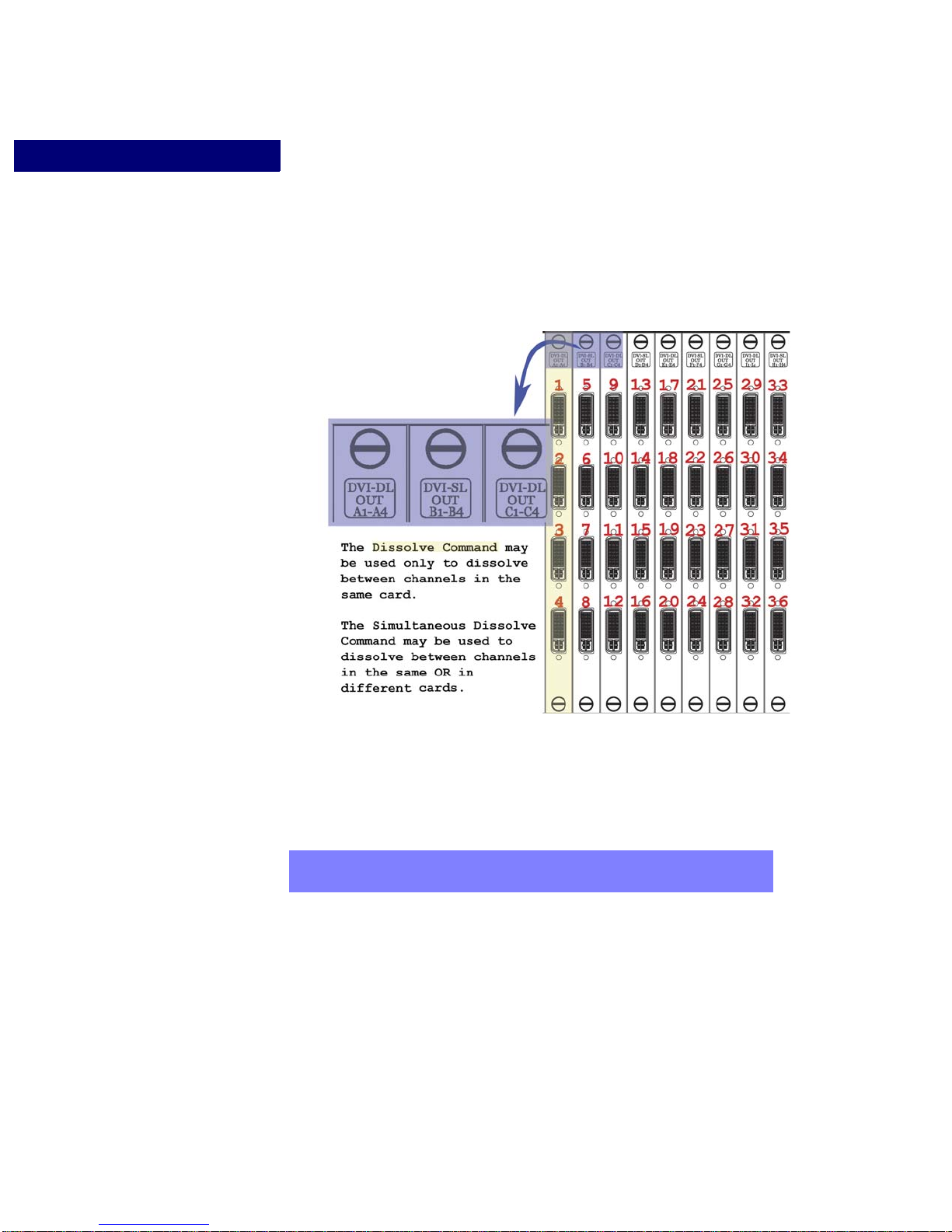
DISSOLVE AND FORCE EFFECTS
. . . . . . . . . . . . . . . . . . . . . . . . . . . . . . . . . . . . . . . . . . . . . . . . . . . .
Output Timing Synchronization
cards. For example, you may dissolve from channels 1 to any other channel on card A, and
at the same time dissolve from output 9 to any other channel on card C.
FIGURE 20. CXPS Dissolve Capabilities
OUTPUT TIMING SYNCHRONIZATION
NOTE:
Before the dissolve or force functions are set up, the timing of each output channel that will
be involved in the effect must be synchronized to the first output channel on that card. This
includes the channel connected to the display, and also the channel you will be dissolving to
or from.
This means that you will have to synchronize only one card when setting up a standard
dissolve or force effect, or a simultaneous dissolve between channels that share the same
card. However, if you plan to simultaneously dissolve between channels on different cards,
78 Operation Edition 1.07 CXPS Manual
Output timing synchronization must be performed manually when using
RS-232/Telnet control.
Page 85

DISSOLVE AND FORCE EFFECTS
Output Timing Synchronization
you will have to follow synchronization procedure several times- once for each card
involved- before setting up the dissolve effect.
. . . . .
NOTE:
There are two different procedures to follow when synchronizing output timing- one for
when the output display screen used in the effect is connected to the first channel on the
card, and one for when it is not.
If you will be forcing, dissolving, or simultaneously dissolving to black
ONLY (not between any output channels), you do not need to
synchronize output timings before setting up the dissolve or force effects.
When the Display is Connected to the First Channel on the Card:
OUTPUT TIMING SYNCHRONIZATION
Before setting up the dissolve or force effect, issue the Framesync command, which
synchronizes the output timing of each output channel that will participate in the dissolve
effect to that of the first output channel on that card.
The command is:
FRAMESYNC <master> <slave1>...<slave3>
Where:
• <master> is the first channel on the card, to which the display is connected.
• <slave1>...<slave3> are the o ther channels on the same card as <master> that you would
like to use in the dissolve or force effect (the “before” video and the “after”)
EXAMPLE
Suppose you want to dissolve on output display 5, which is connected to output
channel 5. This would mean that the display is connected to the first channel on
the card, as shown in Figure 20. If you want to dissolve from output channel 6 to
output channel 8 on display 5, you would first need to synchronize the output
timing of output channels 6 and 8 to that of output channel 5. The command
would be:
When the Display is NOT Connected to the First Channel on the Card:
OUTPUT TIMING SYNCHRONIZATION
CXPS Manual Edition 1.07 Operation 79
FRAMESYNC 5 6 8
•ut timing of the display screen (see Step 1 for help finding this number).
Page 86

DISSOLVE AND FORCE EFFECTS
Output Timing Synchronization
STEP 1: THE HOSTLIST COMMAND
Use the Hostlist command to find the number that represents the resolution of
your chosen output display.
To di splay the host table , use the HOSTLIST co mmand, which will produce a list
of output timings for each display’s r esolution. Find the resolution of your chosen
display screen, and use the corresponding number with the SETOT command in
the next step.
STEP 2: THE SETOT COMMAND
Use the Set Output Timing command to set the output timing of the first output
channel on the card to that of the display screen you plan to use.
The command is:
SETOT <output #> <host>
Where:
•<output #> is the number of the first output channel on the card.
•<host> is a number from the host table that represents the output timing of the
display screen (see Step 1 for help finding this number).
STEP 3: THE FRAMESYNC COMMAND
Issue the Framesync command to synchronize the output timings of both channels
involved in the effect and also of the channel connected to the display to the
timing of the first output channel on that card.
The command is:
FRAMESYNC <master> <slave1>...<slave3>
•Where:
•<master> is the first channel on the card.
•<slave1>...<slave3> are the other channels on the same card as <master>,
including the channel connected to the output display and both channels that
will be involved in the dissolve/force effect. There are up to three slave
channels possible.
EXAMPLE
Suppose you want set up the dissolve or force effect on output display 14, which
is connected to channel 14. You have one window on this display, on channel 15.
You would like to dissolve from channel 15 to channel 16 within this window.
80 Operation Edition 1.07 CXPS Manual
Page 87

Remember, the display’s channel, channel 14, is the second channel on the card,
. . . . . . . . . . . . . . . . . . . . . . . . . . . . . . . . . . . . . . . . . . . . . . . . . . . .
as shown in Figure 20. Therefore, you would have to follow the three steps
described earlier in this section.
STEP 1: Enter the command HOSTLIST and find the resolution of output display
14 on the host table. If output display 14 has a resolution of 1280x1024, the
corresponding number for that resolution is: 5.
STEP 2: Set the output timing of the first output channel on the card, channel 13,
to that of output display 14 using the SETOT command. The command would be:
SETOT 13 5
STEP 3: Synchronize the output timings of channels 14 (the display), 15, and 16
with the first channel on that card, channel 13. The command would be:
FRAMESYNC 13 14 15 16
DISSOLVE AND FORCE
DISSOLVE AND FORCE EFFECTS
Dissolve and Force
. . . . .
The Dissolve RS-232/Telnet commands allow the user to dissolve or force one output or
window, while the Simultaneous Dissolve Output (SDO) commands allow the user to
dissolve several outputs or windows simultaneously. With these commands’ capabilities,
the user is able to dissolve or force from window to window or from output to output. A
user may also dissolve or force from a window to its windowing output- this will fade a
window away, revealing the portion of the background that it had previously concealed.
NOTE:
Before setting up a dissolve or force effect, the timing of each output
channel involved must be synchronized to the first output channel on
that card. See “Output Timing Synchronization” on page 78.
An example of the force effect can be seen in Figure 21 on page 82
CXPS Manual Edition 1.07 Operation 81
Page 88
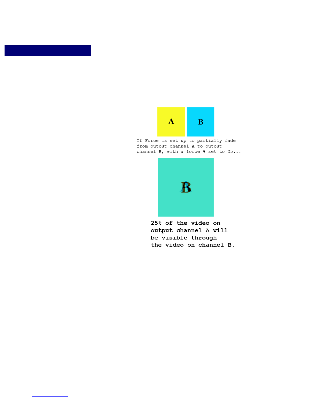
DISSOLVE AND FORCE EFFECTS
Dissolve and Force
FIGURE 21. The Force Effect
Dissolve and Force
The Dissolve commands allow the user to dissolve or force one window or output. The three
steps involved are listed below.
STEP 1. SET UP WINDOWING IF DESIRED
If you would like to dissolve or force a window, you must set up windowing mode prior to
setting up the dissolve effect.
You can choose to use either standard windowing mode or picture-in-picture mode. For
instructions on setting up standard windowing, see “Output Timing Synchronization” on
page 57 or see “Picture-In-Picture” on page 60 for help setting up picture-in-picture mode.
82 Operation Edition 1.07 CXPS Manual
Page 89

DISSOLVE AND FORCE EFFECTS
Dissolve and Force
STEP 2. SET UP THE DISSOLVE OR FORCE EFFECT
To set up dissolve or force effect settings, use the command:
DISSETUP <output #> <from source> <type> <dissolve rate or
force %>
Where:
• <output #> is the output or window whose video is gradually replaced by the video
from <from source>.
It is a number 1-36 corresponding to the output channel connected to the window/output
you would like to select.
• <from source> is the output or window whose video replaces the video from
<output #>.
It is a number 1-36 corresponding to the output channel connected to the window/display
you would like to select, or the number 100 if you would like to fade to black.
. . . . .
NOTE:
• <type> is either “dissolve” or “force”.
• <dissolve rate or force %> is the number of frames (1-1024) for the dissolve
STEP 3. DISSOLVE OR FORCE
To perform the dissolve or force effect, issue either the Dissolve or Dissolve FlipFlop
command.
The Dissolve Command
There are two different arguments you can use when issuing the DIS command. The first,
DIS <output #>, can be used to dissolve or fade between the channels in any dissolve
pair. The second, DIS <output #> <delay rate> can only be used to dissolve (not
force) between a window and the windowing display screen when they share the same
output channel. Using this argument, the selected window will dissolve away, and then,
after a set delay period, dissolve back into view.
When dissolving from a window to its background, <output #> and <from
source> will both be the number of the channel connected to the chosen output
display.
Selecting “force” will allow you to partially fade from <output #> to <from
source>, while selecting “dissolve” will allow you to dissolve.
transition, or, if you choose to force, the percentage of <o utput #> visible through <from
source>.
A dissolve rate of 1 will create an immediate “cut” transition rather than a dissolve.
CXPS Manual Edition 1.07 Operation 83
Page 90

DISSOLVE AND FORCE EFFECTS
Dissolve and Force
• DIS <output #>
Where:
<Output #> is identical to the output number specified in setup.
•When dissolving, issue this command again to dissolve from <from source>
back to <output #>
•When forcing, issuing this command again will produce no effect.
See Figure 21 on page 82 for an example of the Force effect.
• DIS <output #> <delay rate>
Where:
<output #> is identical to the output number specified in setup.
<delay rate> is the number of frames (1-1024) for the delay.
NOTE:
The delay rate feature can only be used when dissolving from a window
to its background.
EXAMPLE:
In Dissolve Setup (Step 1), you set up a dissolve effect to dissolve Window 5 to
reveal its background on Output display 7. You would like Window 5 to dissolve
away, and after a delay of 60 frames, dissolve back into view. The command
initiate the effect is:
DIS 7 60
The Dissolve FlipFlop Command
The DISFF Command can be used to dissolve (not force) between two output channels that
are not under windowing mode. The full effect of this command will not be visible unless
display screens are connected to both channels in the dissolve pair.
When the DISFF command is issued , the video from one display screen (Display screen A)
will be gradually replaced by that from another display screen (Display Screen B). Once the
dissolve is complete, the video that had appeared on Display screen A before the dissolve
will be immediately switched to fill Display screen B.
DISFF <output #>
Where:
<output #> is identical to the output number specified in setup.
84 Operation Edition 1.07 CXPS Manual
Page 91

DISSOLVE AND FORCE EFFECTS
• Issuing this command again will reverse the effect.
Dissolve and Force
. . . . .
NOTE:
TO DELETE DISSOLVE SETTINGS
To reset output parameters to default settings, use the command:
DISDEL <output #>
Where:
• <output #> is identical to the output number specified in setup.
Simultaneous Dissolve Output
The Simultaneous Dissolve Output (SDO) commands allow users to simultaneously
dissolve multiple groups of windows or outputs by storing output-source pairs in ten
different preset slots. A user may also dissolve from mul ti ple windows to their
backgrounds- this will fade the chosen windows away, revealing the portions of the
background that had previously obstructed.
The DISFF command can only be used when dissolving between two
output channels that are NOT under windowing mode.
These channels must be connected to display screens.
EXAMPLE:
In Dissolve Setup (Step 1), you set up a dissolve effect to dissolve from the video
on Output display 1 to the video on Output display 2. Once the Dissolve is
complete, you would like the video that had appeared on Output display 1 to
immediately display on Output display 2. The command is
DISFF 1
The maximum number of dissolve pairs is equal to the maximum channels installed. The
steps needed to simultaneously dissolve are listed below.
NOTE:
STEP 1. SET UP WINDOWING IF DESIRED
If you would like to simultaneously dissolve windows, you must set up windowing mode
prior to setting up the simultaneous dissolve effect.
CXPS Manual Edition 1.07 Operation 85
Before setting up the simultaneous dissolve effect, the timing of each
output channel involved must be synchronized to the first output
channel on that card. See “Output Timing Synchronization” on page 78.
If you plan to simultaneously dissolve between channels on different
cards, you will have to follow synchronization procedure several timesonce for each card involved, before setting up the dissolve effect.
Page 92

DISSOLVE AND FORCE EFFECTS
Dissolve and Force
See “Standard Window Function” on page59 or “Picture-In-Picture” on page 60 for
instructions on setting up standard windowing or picture-in-picture modes.
EXAMPLE
Set Output 2 to display as a window in the foregrounds of Outputs 1 and 3 by
issuing the picture-in-picture commands:
PIPON 1 2 1
PIPON 3 2 3
Then set Output 8 to display as a window in the foregrounds of Outputs 5 and 6 by
issuing the commands:
PIPON 5 8 5
PIPON 6 8 6
STEP 2. SET SIMULTANEOUS DISSOLVE PAIRS
To set up simultaneous dissolve settings, use the command:
SDO <preset #> <dissolve rate> <output #> <from source> ...
<output #> <from source>
Where:
• <preset #> refers to the preset slot (1-10) to which you would like to store dissolve
pairs.
• <output #> <from source> represents a dissolve pair .
• <output #> is the output or window whose video is gradually replaced by the video
from <from source>.
It is a number 1-36 corresponding to the output channel connected to the window/output
you would like to select.
• <from source> is the output or window whose video replaces the video from
<output #>.
It is a number 1-36 corresponding to the output channel connected to the window/display
you would like to select, or the number 100 to dissolve to black.
NOTE:
When dissolving from a window to its background, <output #> and <from
source> will both be the number of the channel connected to the chosen
output display.
• <dissolve rate> is the number of frames (1-1024) for the dissolve effect.
86 Operation Edition 1.07 CXPS Manual
Page 93

DISSOLVE AND FORCE EFFECTS
Dissolve and Force
Choosing a dissolve rate of 1 will create a quick video “cut” transition, rather than a
more gradual video dissolve transition.
EXAMPLE
After setting up picture-in-picture mode in the previous example, and choosing
the dissolve rate of 120, the command is:
SDO 1 120 1 3 5 6
This sets preset 1 to trigger output 1 to dissolve into output 3, and output 5 to
dissolve into output 6 at a rate of 120.
STEP 3. DISSOLVE
To perform the simultaneous dissolve effect, issue the command:
SDORUN <preset #>
EXAMPLE
According to the setup of the previous two steps’ examples, the command is:
. . . . .
SDORUN 1
TO DELETE SIMULTANEOUS DISSOLVE SETTINGS
To remove a particular preset number’s simultaneous dissolve settings, issue the command:
SDODEL <preset #>
CXPS Manual Edition 1.07 Operation 87
Page 94

DISSOLVE AND FORCE EFFECTS
Dissolve and Force
88 Operation Edition 1.07 CXPS Manual
Page 95
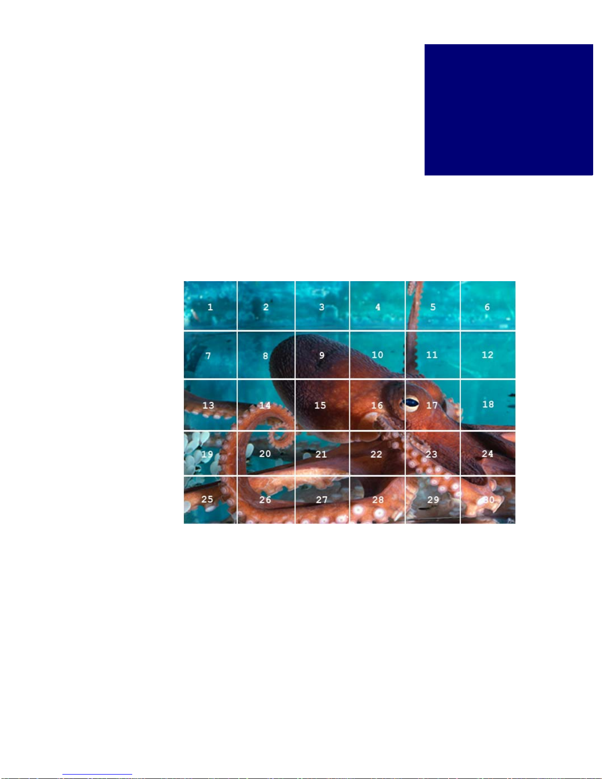
. . . . .
. . . . . . . . . . . . . . . . . . . . . . . . . . . . . . . . . . .
W
. . . . . . . . . . . . . . . . . . . . . . . . . . . . . . . . . . . . . . . . . . . . . . . . . . . .
. . . . . . . . . . . . . . . . . . . . . . . . . . . . . . . . . . . . . . . . . . . . . . . . . . . .
ALL
P
ROCESSING
ABOUT WALL PROCESSING
The CXPS can route any input source to several output displays, which work together in
unison to create one very large display, or “wall,” as shown in Figure 22.
11
FIGURE 22. Wall Display Example
WALL DISPLAY OUTPUT ARRANGEMENT
The output displays in the wall should be organized from left to right by channel number
into equally-sized rows, as demonstrated in Figure 22.
CXPS Manual Edition 1.07 Operation 89
Page 96

WALL PROCESSING
. . . . . . . . . . . . . . . . . . . . . . . . . . . . . . . . . . . . . . . . . . . . . . . . . . . .
Output Timing Synchronization
OUTPUT TIMING SYNCHRONIZATION
Overview
The output timings of every output display in the wall must be the same. Before wall
function is enabled, the timing of each output in the wall must be synchronized to the timing
of the first output in the wall using RS-232/Telnet commands.
Setting the Output Timing:
You may set the output timing of the first output in your wall (the display in the upper left
hand corner of your wall), and then synchronize all other outputs to this new timing. If you
are satisfied with the current output timing of the first output in your wall, proceed to the
next section, “Synchronizing Output Timings” on page 90.
To set the output timing of your first display, follow these 2 steps:
STEP 1: THE HOSTLIST COMMAND
Use the Hostlist command to find the number that represents the resolution of your output
displays.
To display the host table, use the HOSTLIST command, which will produce a list of output
timings for each display’s resolution. Find the resolution of your chosen displays, and use
the corresponding number with the SETOT command in the next step.
STEP 2: THE SETOT COMMAND
Use the Set Output Timing command to set the output timing of the first output channel
used in the wall to that of the display screens you plan to use.
The command is:
SETOT <first output #> <host>
Where:
• <first output #> is the number of the first output channel used in the wall.
• <host> is a number from the host table that represents the output timing of the display
screens (see Step 1 for help finding this number)
Proceed to “Synchronizing Output Timings” to complete output synchronization.
Synchronizing Output Timings
Before wall function is enabled, the timing of each output in the wall must be synchronized
to the timing of the first output in the wall using the Framesync or GFramesync comma nd.
90 Operation Edition 1.07 CXPS Manual
Page 97

WALL PROCESSING
. . . . . . . . . . . . . . . . . . . . . . . . . . . . . . . . . . . . . . . . . . . . . . . . . . . .
Wall Processing Function
THE FRAMESYNC COMMAND
Use the Framesync command to specify every channel you would like to synchronize to the
first output. The command is:
FRAMESYNC <first output #> <slave1>...<slave35>
Where:
• <first output #> is the first output channel used in your wall.
• <slave1>...<slave35> are the other output channels used in your wall, with a total of up
to 35 slave channels possible (if your CXPS has 36 outputs).
• Example:
Suppose you want to create a 2x3wall using displays connected to output channels 2, 3,
4, 9, 10, and 11. You must synchronize the timings of output channels 3, 4, 9, 10, and 11
with that of output channel 2, the first output in the wall. The command would be:
FRAMESYNC 2 3 4 9 10 11
. . . . .
THE GFRAMESYNC COMMAND
You may use the GFRAMESYNC command to synchronize the timings of a range of
outputs to the timing of the first output in the range. The command is:
GFRAMESYNC <first output #> <last output #>
Where:
• <first output #> is the first output channel used in your wall (and the first output
in the range).
• <last output #> is the last output channel in the range.
• Example:
Suppose you want to create a 2x3 wall using output displays connected to channels 1
through 6. You would need to synchronize the output timings of channels 2 through 6
with that of output 1. The command would be:
GFRAMESYNC 1 6
WALL PROCESSING FUNCTION
The CXPS can support multiple walls. Each wall is identified by its first output number.
CXPS Manual Edition 1.07 Operation 91
Page 98

WALL PROCESSING
Wall Processing Function
Enabling Wall Processing Function
WHEN THE OUTPUTS USED ARE IN A RANGE
To turn the wall processing on when the outputs used by your wall are in a range, iss ue the
command:
WALL <input#> <first output#> <column> <row> ON
Where:
• <input #> is the input you would like to route to the wall display.
• <first output#> is the channel number of the first output display in the wall.
(the display located at the upper left-hand corner of the wall).
• <column> and <row> specify the size of the wall:
<column> is the number of output displays wide.
<row> is the number of output displays high.
For example, to create the wall shown in Figure 22 and route input 3 to it, the command
would be:
WALL 3 1 6 5 ON
WHEN THE OUTPUTS USED ARE NOT IN A RANGE
If you skipped outputs when making your wall, like the wall in Figure 23, you will need to
specify the outputs used when enabling wall function. Enable wall function by issuing the
command:
WALL <input#> <first output#> <column> <row> <output #> ...
<output #> ON
Where:
• <input #> is the input you would like to route to the wall display.
• <first output#> is the channel number of the first output display in the wall.
(the display located at the upper left-hand corner of the wall).
• <column> and <row> specify the size of the wall:
<column> is the number of output displays wide.
<row> is the number of output displays high.
92 Operation Edition 1.07 CXPS Manual
Page 99
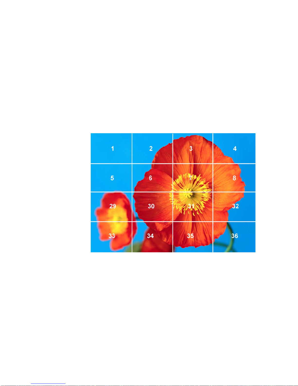
WALL PROCESSING
. . . . . . . . . . . . . . . . . . . . . . . . . . . . . . . . . . . . . . . . . . . . . . . . . . . .
Adjusting Wall Position
• <output #> ... <output #> are the channel numbers other than <first
output#> that are used in the wall. They should be listed in order from left to right,
top to bottom.
For example, to create the 4x4 wall shown in Figure 23 and route input 13 to it, you would
issue the command:
WALL 13 1 4 4 2 3 4 5 6 7 8 29 30 31 32 33 34 35 36 ON
. . . . .
FIGURE 23. 4x4 Wall
Disabling Wall Processing Function
To turn wall processing function off, issue the command:
WALL <first output #> OFF
ADJUSTING WALL POSITION
To interactively adjust the position of the wall, issue the command:
WALLADJ <first output #>
CXPS Manual Edition 1.07 Operation 93
Page 100
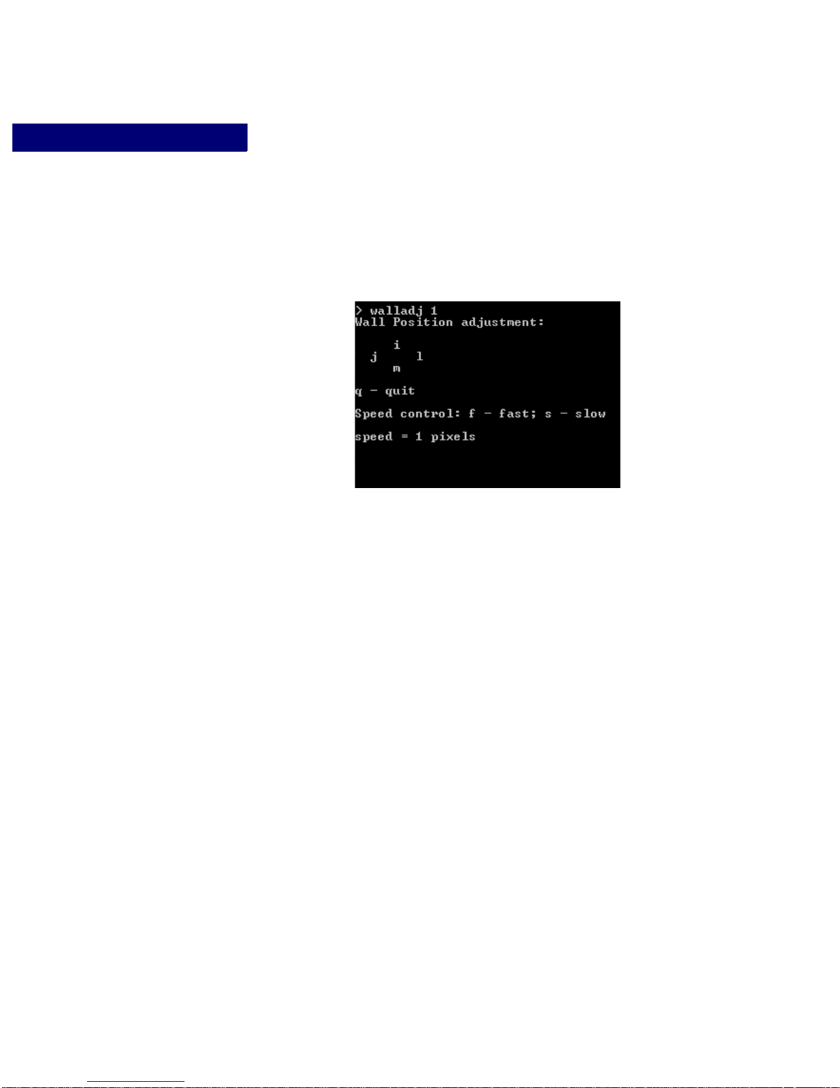
WALL PROCESSING
. . . . . . . . . . . . . . . . . . . . . . . . . . . . . . . . . . . . . . . . . . . . . . . . . . . .
Switching Input Sources
This will cause the wall adjustment control field to appear, as shown in Figure 24.
FIGURE 24. The Wall Adjustment Control Field
Wall Position Adjustment Control:
• To move the wall’s position to the left one preset increment, press the lower-case “j”
key.
• T o move the wall’s position to the right one preset inc rement, press the lower-case “l”
key.
• To move the wall’s position up one preset increment, press the lower-case “i” key.
• To move the wall’s position down one preset increment, press the lower-case “m” key.
Speed Control:
• To increase the adjustment speed, press the lower-case “f” key.
• To decrease adjustment speed, press the lower-case “s” key.
• Each time the “f” or “s” key is pressed, the speed is adjuste d by 1 prese t increment of
pixels.
SWITCHING INPUT SOURCES
The input source routed to a wall can be switched using the RS-232/Telnet Wall Switch
command. When selecting a different input to display on the wall outputs, issue the
command:
WALLSW <input #> <first output #>
94 Operation Edition 1.07 CXPS Manual
 Loading...