

Page 1
www.bdsensors.com
DE EN
Deutsch
Montageanleitung /
Mounting instructions
Füllstandssonde für Marine und Offshore/
Probe for Marine and Offshore
LMK 457, LMK 458, LMK 458H, LMK 487
Zentrale Osteuropa
BD SENSORS GmbH BD SENSORS s.r.o.
BD-Sensors-Str. 1 Hradištská 817
D - 95199 Thierstein CZ - 687 08 Buchlovice
Deutschland Tschechische Republik
Tel.: +49 (0) 92 35 / 98 11-0 Tel.: +42 (0) 572-4110 11
Fax: +49 (0) 92 35 / 98 11-11 Fax: +42 (0) 572-4114 97
Russland
BD SENSORS RUS
39a, Varshavskoe shosse
RU - Moscow 117105
Russland
Tel.: +7 (0) 9 59 81 / 09 63
Fax: +7 (0) 9 57 95 / 07 21
China
BD SENSORS China Co, Ltd.
Room B, 2nd Floor, Building
10, No. 1188 Lianhang Rd.
201112 Shanghai,
China
Tel.: +86 (0) 21-51600 190
Fax: +86 (0) 21-33600 613
Diese Montageanleitung stellt einen Auszug
aus der ausführlichen Betriebsanleitung dar.
Bitte laden Sie sich diese auf unserer Homepage herunter, falls Sie nicht mit dem Produkt
vertraut sind.
These mounting instructions are an excerpt from the complete
operating manual. It may be downloaded from our homepage, if
you are not familiar with the device.
http://www.bdsensors.de
http://www.bdsensors.com
– Technische Änderungen vorbehalten –
– Technical modifications reserved –
WARNUNG! Um Gefährdungen des Bedienpersonals und
Schäden am Gerät auszuschließen, müssen die beschriebenen Arbeiten von qualifiziertem Fachpersonal durchgeführt werden.
WARNUNG! Halten Sie sich an Sicherheitshinweise und
Handlungsanweisungen, die in der Betriebsanleitung aufgeführt werden. Zusätzlich sind die geltenden Unfallverhütungsvorschriften, Sicherheitsbestimmungen sowie landesspezifische Installationsstandards und die anerkannten Regeln der Technik einzuhalten.
Haftungsbeschränkung
Bei Nichtbeachtung der Betriebsanleitung, unsachgemäßer
Verwendung, Veränderung oder Beschädigung des Gerätes
übernimmt der Hersteller keine Haftung.
Bestimmungsgemäße Verwendung
Stellen Sie sicher, dass das Messmedium mit den medienberührten Teilen verträglich und das Gerät uneingeschränkt
für die Anwendung geeignet ist. Die im aktuellen Datenblatt
aufgeführten technischen Daten sind verbindlich.
Produktidentifikation
Anschlussbelegungstabelle
Elektrische Anschlüsse Kabelfarben (IEC 60757)
Versorgung
Versorgung
optional (bei Pt 100):
Versorgung T+
Versorgung T–
Versorgung T–
wh (weiß)
bn (braun)
ye (gelb)
gy (grau)
pk (rosa)
Schirm gnye (grün-gelb)
Anschlussschaltbild
LMK 458H:
Verwenden Sie für den elektrischen Anschluss eine
abgeschirmte und verdrillte Mehraderleitung
Montage
Zertifikate
Bestell-
code
Mess-
bereich
Typen-
bezeichnung
Anschlussbelegung Versorgung
Signal
Serien-
nummer
Versorgung UB+
Versorgung UB
Versorgung T+
Versorgung T
Versorgung T
UB
bei
Pt 100
p
I
LMK 458
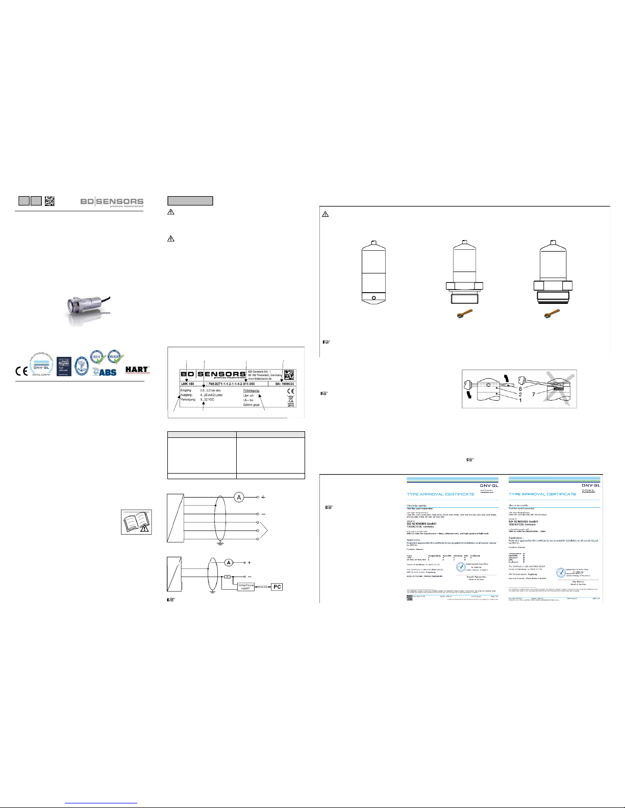
WARNUNG! Montieren Sie das Gerät immer im druck- und stromlosen Zustand!
Tauchsonde Flanschsonde Einschraubsonde
ca. 25 Nm G3/4": ca. 15 Nm
G1": ca. 25 Nm
Standardmäßig wird die Füllstandssonde ohne Montagezubehör geliefert.
Verschiedenes Zubehör ist bei BD SENSORS erhältlich (Schellenbefestigung, Abspannklemmen sowie Montage- und
Sondenflansche).
LMK 458H:
p
Versorgung +
Versorgung –
UB
I
Die Füllstandssonden
LMK 457, LMK 458,
LMK 458 H und LMK 487
erfüllen standardmäßig die
Anforderungen des DNV▪GL
(Det Norske Veritas ▪
Germanischen
Lloyd ).
Die Zertifikate können Sie auf
unserer Homepage
herunterladen:
http:// www.bdsensors.de
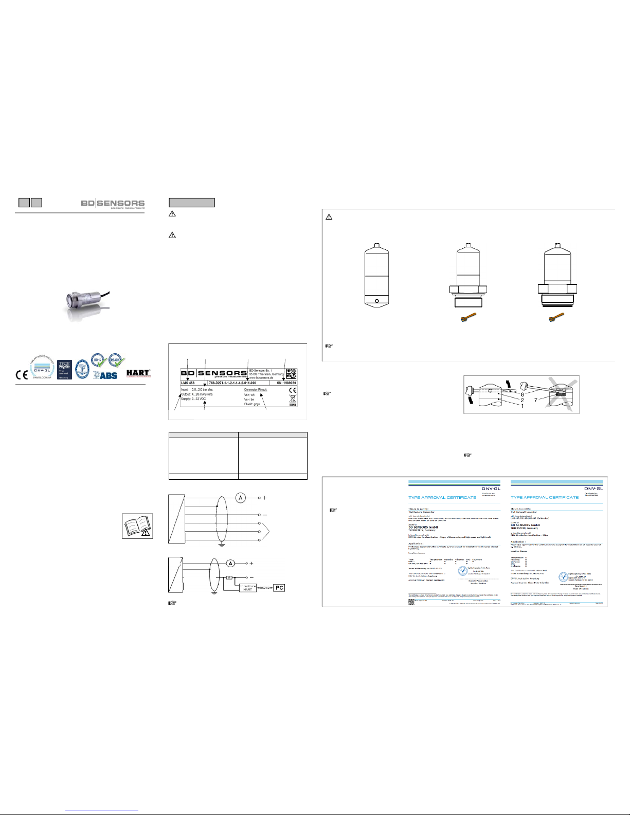
Abziehen der Schutzkappe (falls erforderlich)
Ist ein Einsatz der Tauchsonde in höher viskosen Medien vorgesehen, so müssen Sie vor Inbetriebnahme die Schutzkappe
(falls vorhanden) vorsichtig abziehen.
Halten Sie sich bitte genau an die nachfolgenden Anweisungen um eine Beschädigung der Membrane zu verhindern.
Abziehen von Hand
- Halten Sie die Tauchsonde so, dass die Schutzkappe
nach oben zeigt.
- Halten Sie mit einer Hand die Sonde am Sondenteil (1)
fest.
- Ziehen Sie mit der anderen Hand die Schutzkappe (2)
ab.
Abziehen mit Werkzeug (empfohlen)
- Halten Sie die Tauchsonde so, dass die Schutzkappe
nach oben zeigt.
- Schieben Sie ein dünnes Werkzeug (8), z. B. ein en
Schraubendreher, gerade durch zwei gegenüberliegende
Bohrungen der Schutzkappe (2).
- Hebeln Sie die Schutzkappe vorsichtig ab, indem Sie den
Griff des Schraubenziehers nach oben bewegen.
Achten Sie dabei unbedingt darauf, dass Sie die Messzelle (7) unter der Schutzkappe nicht beschädigen!
Page 2
MA_FS für Schifffahrt_180118
DE EN
Englisch
www.bdsensors.com
Montageanleitung /
Mounting instructions
Füllstandssonde für Marine und Offshore/
Probe for Marine and Offshore
LMK 457, LMK 458, LMK 458H, LMK 487
Headquarters Eastern Europe
BD SENSORS GmbH BD SENSORS s.r.o.
BD-Sensors-Str. 1 Hradištská 817
D - 95199 Thierstein CZ - 687 08 Buchlovice
Germany Czech Republic
Tel.: +49 (0) 92 35 / 98 11-0 Tel.: +42 (0) 572-4110 11
Fax: +49 (0) 92 35 / 98 11-11 Fax: +42 (0) 572-4114 97
Russia
BD SENSORS RUS
39a, Varshavskoe shosse
RU - Moscow 117105
Russia
Tel.: +7 (0) 9 59 81 / 09 63
Fax: +7 (0) 9 57 95 / 07 21
China
BD SENSORS China Co, Ltd.
Room B, 2nd Floor, Building
10, No. 1188 Lianhang Rd.
201112 Shanghai,
China
Tel.: +86 (0) 21-51600 190
Fax: +86 (0) 21-33600 613
Diese Montageanleitung stellt einen Auszug
aus der ausführlichen Betriebsanleitung dar.
Bitte laden Sie sich diese auf unserer Homepage herunter, falls Sie nicht mit dem Produkt
vertraut sind.
These mounting instructions are an excerpt from the complete
operating manual. It may be downloaded from our homepage, if
you are not familiar with the device.
http://www.bdsensors.de
http://www.bdsensors.com
– Technische Änderungen vorbehalten –
– Technical modifications reserved –
WARNING! In order to avoid hazards to operators and damages to the device, the following instructions have to be performed by qualified technical personnel.
WARNING! Adhere to the safety and operating instructions
stated in the operation manual. Effective regulations on occupational safety, accident prevention as well as national installation standards and approved engineering techniques
must in addition be complied with.
Limitation of liability
If the instructions in the operating manual are not adhered to
or if the device is inappropriately used, modified or damaged, liability is not assumed and warranty claims will be excluded.
Intended use
Ensure that the medium is compatible with the media-wetted
parts and that the device is suitable for the application without restrictions. The technical data listed in the current data
sheet is binding.
Product identification
Pin configuration
Electrical connection cable colours (IEC 60757)
Supply
Supply
optionally (only Pt 100):
Supply T+
Supply T–
Supply T–
wh (white)
bn (brown)
ye (yellow)
gy (grey)
pk (pink)
Shield gnye (green-yellow)
Wiring diagram
LMK 458H:
For the electrical connection, a shielded and twisted
multicore cable has to be used.
Mounting
Certificates
ordering
code
nominal
pressure range
type
designation
connector pinout supply signal
serial
number
p
supply +
supply –
VS
I
supply VS+
supply VS
supply T+
supply T
supply T
VS
only
Pt 100
p
I
LMK 458
LMK 458H:
The probes LMK 457,
LMK 458, LMK 458 H
and , LMK 487 fulfil the
requirements of DNV▪GL
(Det Norske Veritas ▪
Germanischen Lloyd) as
standard.
The certificates
are available for download
on our homepage:
http:// www.bdsensors.com
Removing the protection cap (if necessary)
If the device shall be used in high-viscosity media, a careful
removal of the cap before start-up is necessary (if existing).
To prevent a damage of the diaphragm, please follow
these instructions.
Removal by hand
- Hold the probe in a way that the protection cap points
upwards.
- Hold the probe with one hand on the sensor section (1).
- Remove the protection cap (2) with the other hand.
Removal with a tool (recommended)
- Hold the probe in a way that the protection cap points upwards.
- Slide a small tool such as a screwdriver (8) straight
through two opposite drill holes in the protective cap (2).
- Lever it off by moving up the handle of the screwdriver.
Make sure that the sensor (7) under the protection cap
will not be damaged!
WARNING! Install the device only in depressurized and currentless state!
Probe Flange version Screw-in version
approx. 25 Nm G3/4": appro x. 15 Nm
G1": approx. 25 Nm
Usually, the hydrostatic probe is delivered without mounting accessoires.
Different accessoires are available from BD SENSORS (mounting clamp, terminal clamp, mounting or tr ansmitter flange).
 Loading...