

Page 1
www.bdsensors.com
DE
EN
Deutsch
Montageanleitung /
Mounting instructions
Digitalmanometer / Digital pressure gauge
BAROLI 02, 02 P, 05, 05 P
Zentrale
BD SENSORS GmbH
BD-Sensors-Str. 1
D - 95199 Thierstein
Deutschland
Tel.: +49 (0) 9235-9811-0
Fax: +49 (0) 9235-9811-11
Osteuropa
BD SENSORS s.r.o.
Hradištská 817
CZ - 687 08 Buchlovice
Tschechische Republik
Tel.: +42 (0) 572-4110 11
Fax: +42 (0) 572-4114 97
Russland
BD SENSORS RUS
39a, Varshavskoe shosse
RU - Moscow 117105
Russland
Tel.: +7 (0) 95-380 1683
Fax: +7 (0) 95-380 1681
China
BD SENSORS China Co, Ltd.
Room B, 2nd Floor, Building
10, No. 1188 Lianhang Rd.
201112 Shanghai,
China
Tel.: +86 (0) 21-51600 190
Fax: +86 (0) 21-33600 613
Diese Montageanleitung stellt einen Auszug
aus der ausführlichen Betriebsanleitung dar.
Bitte laden Sie sich diese auf unserer Homepage herunter, falls Sie nicht mit dem Produkt
vertraut sind.
These mounting instructions are an excerpt from the complete
operating manual. It may be downloaded from our homepage, if
you are not familiar with the device.
http://www.bdsensors.de
http://www.bdsensors.com
– Technische Änderungen vorbehalten –
– Technical modifications reserved –
WARNUNG! Um Gefährdungen des Bedienpersonals und
Schäden am Gerät auszuschließen, müssen die beschriebenen Arbeiten von qualifiziertem Fachpersonal durchgeführt werden.
WARNUNG! Halten Sie sich an Sicherheitshinweise und
Handlungsanweisungen, die in der Betriebsanlei tung aufgeführt werden. Zusätzlich sind die geltenden Unfallverhütungsvorschriften, Sicherheitsbestimmungen sowie landesspezifische Installationsstandards und die anerkannten
Regeln der Technik einzuhalten.
Haftungsbeschränkung
Bei Nichtbeachtung der Betriebsanleitung, unsachgemäßer
Verwendung, Veränderung oder Beschädigung des Gerätes übernimmt der Hersteller keine Haftung.
Bestimmungsgemäße Verwendung
Stellen Sie sicher, dass das Messmedium mit den medienberührten Teilen verträglich und das Gerät uneingeschränkt für die Anwendung geeignet ist. Die im aktuellen
Datenblatt aufgeführten technischen Daten sind
verbindlich.
Produktidentifikation
Batteriewechsel
Um die Batterien zu wechseln gehen
Sie folgendermaßen vor:
- drehen Sie die Kunststoffabdeckung mit Hilfe einer Münze
(z.B. 2 €-Münze) um 45° gegen
den Uhrzeigersinn bis zum Anschlag
- halten Sie die Münze weiterhin
fest und hebeln Sie mit ihrer Hilfe
die Kunststoffabdeckung seitlich
nach oben heraus
- nehmen Sie die Abdeckung ab und wechseln Sie die Batterien
- verschließen Sie anschließend das Gerät wieder ordnungsgemäß
Anzeige- und Bedie nm o d ul
Montage
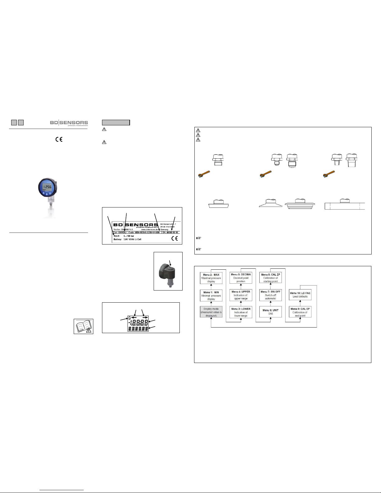
Aufbau des Menüsystems
▲ / on-Taste: Einschalten des Gerätes
im Menüsystem vorwärts bewegen
Anzeigewert erhöhen
▼ / off-Taste: Ausschalten des Gerätes
im Menüsystem rückwärts bewegen
Anzeigewert verringern
OK-Taste: Aktivierung des Bedienmodus und der
einzelnen Menüpunkte
Bestätigung der eingestellten Werte
Bestellcode
Typenbezeichnung
Nenn-
druck
Serien-
nummer
Kunststoffabdeckung
über Batteriefach
Bereichsüberschreitung
neg. / pos.
Batterie-
stands
-
anzeige
Einheitenanzeige
Messwertanzeige
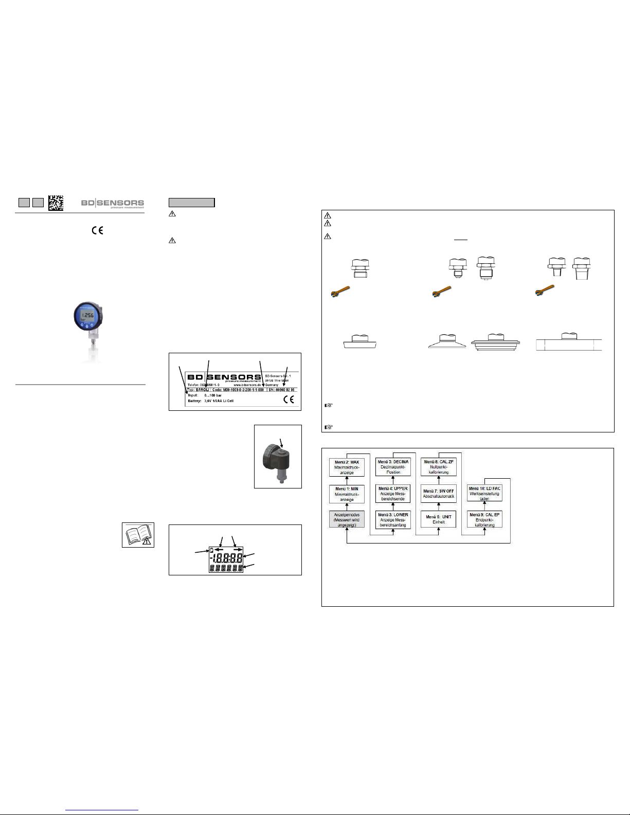
WARNUNG! Montieren Sie das Gerät immer im druck- und stromlosen Zustand!
WARNUNG!
Verwenden Sie zur Abdichtung eine geeignete Dichtung, entsprechend dem Messstoff und dem zu messenden
Druck.
VERWENDEN SIE (bei Anschluss nach DIN 3852) KEIN ZUSÄTZLICHES DICHTMATERIAL WIE WERG, H
ANF ODER
TEFLONBAND!
Anschluss nach DIN 3852 Anschluss nach EN 837 NPT-Anschluss
G1/4": ca. 5 Nm G1/4": ca. 20 Nm 1/4" NPT: ca. 30 Nm
G1/2": ca. 10 Nm G1/2": ca. 50 Nm 1/2" NPT: ca. 70 Nm
G1": ca. 20 Nm
Die angegebenen Anzugsmomente dürfen nicht überschritten werden!
Milchrohr-Anschluss Clamp- und Varivent
-Anschluss Flansch-Anschluss
- Zentrieren Sie den Anschluss in der - Zentrieren Sie den Anschluss in der Befestigen Sie den Flansch
Aufnahmearmatur. Aufnahmearmatur. mit 4 bzw. 8 Schrauben (je
- Schrauben Sie die Überwurfmutter - Befestigen Sie das Gerät anschließend nach Flanschausführung) am
auf die Aufnahmearmatur. durch ein geeignetes Verbindungselement Gegenflansch.
- Ziehen Sie diese mit einem (z. B. Halbring- oder Klappringverbindung) .
Hakenschlüssel fest. gemäß den vom Hersteller angegebenen
Vorschriften.
Beachten Sie, dass durch die Montage keine unzulässi g hohen mechanischen Spannungen am Dr uckanschluss auftreten, da
diese zu einer Verschiebung der Kennlinie oder zur Beschädigung führen könnte n. Dies gilt ganz besonders für sehr kleine
Druckbereiche sowie für Geräte mit einem Druckanschluss aus Kunststoff.
Weitere wichtige Informationen entnehmen Sie bitte der ausführlichen Bedienungsanleitung.
Page 2
MA_BAROLI_100914
D
E
Englisch
www.bdsensors.com
Montageanleitung /
Mounting instructions
Digitalmanometer / Digital pressure gauge
BAROLI 02, 02 P, 05, 05 P
Headquarters
BD SENSORS GmbH
BD-Sensors-Str. 1
D - 95199 Thierstein
Germany
Tel.: +49 (0) 9235-9811-0
Fax: +49 (0) 9235-9811-11
Eastern Europe
BD SENSORS s.r.o.
Hradištská 817
CZ - 687 08 Buchlovice
Czech Republic
Tel.: +42 (0) 572-4110 11
Fax: +42 (0) 572-4114 97
Russia
BD SENSORS RUS
39a, Varshavskoe shosse
RU - Moscow 117105
Russia
Tel.: +7 (0) 95-380 1683
Fax: +7 (0) 95-380 1681
China
BD SENSORS China Co, Ltd.
Room B, 2nd Floor, Building
10, No. 1188 Lianhang Rd.
201112 Shanghai,
China
Tel.: +86 (0) 21-51600 190
Fax: +86 (0) 21-33600 613
Diese Montageanleitung stellt einen Auszug
aus der ausführlichen Betriebsanleitung dar.
Bitte laden Sie sich diese auf unserer Homepage herunter, falls Sie nicht mit dem Produkt
vertraut sind.
These mounting instructions are an excerpt from the complete
operating manual. It may be downloaded from our homepage, if
you are not familiar with the device.
http://www.bdsensors.de
http://www.bdsensors.com
– Technische Änderungen vorbehalten –
– Technical modifications reserved –
WARNING! In order to avoid hazards to operators and
damages to the device, the following instructions have to
be performed by qualified technical personnel.
WARNING! Adhere to t he safety and operating instructions
stated in the operation manual. Effective regulations on occupational safety, accident prevention as well as national
installation standards and approved engineering techniques must in addition be complied with.
Limitation of liability
If the instructions in the operating manual are not adhered
to or if the device is inappropriately used, modified or damaged, liability is not assumed and warranty cl aims will be
excluded.
Intended use
Ensure that the medium is compatible with the mediawetted parts and that the device is suitable for the appl ication without restrictions. The technical data listed in the current data sheet is binding.
Product identification
Changing the batteries
To change the batteries go ahead
as follows:
- Turn the plastic cap 45° anti
clockwise by a coin (e.g. 2 € coin)
as far as possible.
- Hold the count tight and lever the
plastic ca p o ut o f t he ho usi ng with
help of the count.
- Take the cap off and change the
batteries.
- Lock the device after that properly.
Display and operatin g m odule
Mounting
Structure of the menu system
▲ / on button: turn the device on
move forward in the menu system
increase the displayed value
▼ / off button: turn the device off
move backward in the menu system
decrease the displayed value
OK button: activate the operating mode and the
different menu items
confirm the set values
Ordering code
Type designation
Input
Serial
number
plastic cap above
battery case
limit exceeding
neg. / pos.
symbol for
indicate low
batteries
unit
measured value
WARNING! Install the device only in depressurized and currentless state!
WARNING! Use a suitable seal, corresponding to the medium and the pressure input.
DO NOT USE ANY ADDITIONAL SEALING MATERIALS; LINKE YARN; HEMP OR TEFLON TAPE
(for connection acc. DIN 3852)!
Connection acc. to DIN 3852 Connection acc. to EN 837 NPT connections
G1/4": approx. 5 Nm G1/4": approx. 20 Nm 1/4" NPT: approx. 30 Nm
G1/2": approx. 10 Nm G1/2": approx. 50 Nm 1/2" NPT: approx. 70 Nm
G1": approx. 20 Nm
The indicated tightening torques must not be exceeded!
Dairy pipe connection Clamp and Varivent
connection Flange connection
- Centre the connection - Centre the connection in the Fasten the flange with 4 resp.
in the mounting part. mounting part. 8 screws (depending on
- Screw the cup nut onto the - Fix the device with a suitable fastening flange version) on the counter
mounting part. element (e. g. semi-ring or retractable flange.
- Then tighten it with a hook wrench. ring clamp) according to the supplier’s
instructions.
Take note that no inadmissibly high mechanical stress occurs at the pressure port, since this may cause a shifting of the
characteristic curve or to the dem age. This is especiall y important for very small pressure ra nges as well as for devi ces with a
pressure port made of plastic.
For more information, please read the detailed operating manual!
 Loading...