


DosaLink – 540 Wireless LAN IEEE
802.11 a/b/g Access Point User’s Manual
Version E.1.1
Copyright statement
No part of this publication may be reproduced, stored in a retrieval system, or
transmitted in any form or by any means, whether electronic, mechanical, photocopying,
recording, or otherwise without the prior writing of the publisher.
User’s Manual 1/73
Ver. [E.1.1]

Table of Contents
1. Introduction.............................................................................................................4
2. Features.................................................................................................................... 5
3. Specifications ......................................................................................................... 6
4. Exterior view............................................................................................................ 7
5. Installing the Hardware.........................................................................................8
5.1. Before Installing............................................................................................. 8
5.2. Connecting the Cables.................................................................................9
5.3. Configuration Information...........................................................................9
5.4. Factory Default Setting................................................................................. 9
6. Configure the computer for sharing the Internet ........................................ 10
6.1. Configuration for Windows 2000 and XP .............................................. 10
6.1.1. Obtain an IP address automatically for DosaLink – 540........... 10
6.1.2. Confirm and Renew the IP address ................................................12
6.1.3. Assign the static IP address............................................................. 13
7. Communication between user’s PC and the DosaLink – 540.................. 15
8. Connect the Internet via the configuration window of DosaLink – 540 16
9. Configuration the DosaLink – 540...................................................................21
9.1. ADSL (PPPoE) users...................................................................................21
9.2. Cable and VDSL Users ............................................................................... 22
9.3. Static IP Users ..............................................................................................23
9.4. Remove all the Network related Programs ........................................... 24
10. Network Connection Status..............................................................................24
11. Description the Menu of DosaLink – 540.......................................................25
11.1. LAN Setup..................................................................................................25
11.2.
11.3. Access Control.........................................................................................27
11.4. Port Forwarding........................................................................................ 28
11.5. Static Routing ........................................................................................... 30
11.6. System........................................................................................................30
11.7. Wireless Setup.......................................................................................... 32
11.8. nESA Setup................................................................................................34
11.9. Advanced ................................................................................................... 36
11.10. Wireless Distribution System (WDS)..................................................37
11.11. MAC Filtering.............................................................................................38
11.12. IEEE 802.1x................................................................................................ 39
11.13. Wi-Fi Protected Access (WPA)/ WPA2 (IEEE 802.11i).................... 41
11.14. Virtual Local Area Networks (VLAN) ...................................................43
12. Factory Resetting.................................................................................................44
Server..........................................................................................................26
12.1. Resetting via the Web.............................................................................44
User’s Manual 2/73
Ver. [E.1.1]

12.2. Hardware Reset........................................................................................ 47
13. Configuration via Console................................................................................. 47
13.1. Connection................................................................................................. 47
13.2. Status.......................................................................................................... 49
13.3. LAN Setup..................................................................................................50
13.4. WAN Setup................................................................................................. 51
13.5. Server..........................................................................................................55
13.6. Access Control.........................................................................................57
13.7. Port Forwarding........................................................................................ 58
13.8. Static Routing ........................................................................................... 60
13.9. Wireless Setup.......................................................................................... 61
13.9.1. Primary Setup ...................................................................................62
13.9.2. Advanced Setup............................................................................... 65
13.9.3. WDS..................................................................................................... 66
13.9.4. MAC Filtering..................................................................................... 66
13.9.5. 802.1x.................................................................................................. 67
13.9.6. nESA Key Setup............................................................................... 69
13.9.7. VLAN.................................................................................................... 69
13.9.8. WPA/ WPA2 .......................................................................................70
Appendix I: Abbreviations and Acronyms............................................................ 72
User’s Manual 3/73
Ver. [E.1.1]

1. Introduction
Thank you for purchasing the DosaLink – 540 Wireless LAN Secure Access Point
(AP). This User’s Manual will help you to configure and operate the DosaLink – 540
Access Point.
The other bands exept ISM Band, 5150~5250MHz, shall be used at only Indoor.
The package you have received contains the following items:
- DosaLink – 540 Wireless LAN IEEE 802.11a/b/g Secure AP
- 2 Antennas connected to DosaLink – 540 AP
- AC-DC Power Adapter, Ethernet Cable, and Serial Cable
- CD containing the User’s Manual
Note: if any items are missing, please contact your vendor.
FCC Caution: To assure continued compliance, any changes or modifications
not expressly approved by the party responsible for compliance could void the
user’s authority to operate this equipment.
This device complies with Part 15 of the FCC Rules. Operation is subject to the
following two conditions: (1) This device may not cause harmful interference, and
(2) this device must accept any interference received, including interference that
may cause undesired operation.
FCC RF Exposure Requirements: (Accoding as FCC Part 15.407(f))
The compliance with RF exposure requirements has been demonstrated for both
fundamental and unwanted emissions
This equipment must be installed and operated in accordance with provided
instructions and the antenna(s) used for this transmitter must be installed to
provide a separation distance of at least 20cm from all persons and must not be
co-located or operating in conjunction 20cm wth any other antenna or transmitter.
End-users and installers must be provide with antenna installation instructions
and transmitter operating conditions for satisfying RF exposure compliance.
User’s Manual 4/73
Ver. [E.1.1]

2. Features
Enhance security of your Wireless Local Area Network (WLAN) with the initiation of
the nDosa Enhanced Security Algorithm (nESA
solution is applied to WLAN.
Introduce the novel security key management system - LinkAuthentica
managing the security key of WLAN networks.
Simple installation and configuration:
- Supporting Secure Socket Layer (SSL) Web management (https://).
- Easy to control user interface and display.
- Easy to configure network with regard to user network environments (driving
Dynamic Host Configuration Protocol (DHCP) onto LAN interface).
- Enhanced security over wireless link (The nESA
Supporting Network Address Translation (NAT)
- Minimize the lowering throughput due to NAT by using high speed processing.
TM
). The novel concept of security
TM
TM
is set as default).
– for
- Up to 253 users may be able to share the network simultaneously.
Strong phased security functions:
- The Firewall functioning of NAT is able to block an intrusion from any untrusted
external networks.
- By utilizing the Demilitarized Zone (DMZ) function, it can be served actively for
requesting outside information.
- The security policies can be established by using the Internet Protocol (IP)
Filtering and Media Access Control (MAC) Filtering functions.
- Complete WLAN security solution by using Wired Equivalent Privacy (WEP), WiFi Protected Access (WPA), IEEE 802.1x, nESA, and etc.
- Supporting IEEE 802.1x Extensible Authentication Protocol (EAP)-MessageDigest algorithm 5 (MD5)/ Transport Layer Security (TLS)/ Tunneled Transport
Layer Security (TTLS).
Three 10/100 Mbps Ethernet Ports.
- Cable Auto Sensing (Auto-Medium Dependent Interface Crossover (MDIX))
Supporting Point-to-Point Protocol over Ethernet (PPPoE).
Supporting various Network Protocols.
Supporting Wireless Distribution System (WDS) and Bridge functions.
Supporting Simple Network Management Protocol (SNMP) V1, V2.
User’s Manual 5/73
Ver. [E.1.1]

3. Specifications
WAN Interface
- 10/100Base-TX Auto Negotiation 1 Port (RJ-45) Auto
MDIX
- IEEE802.3af Power Over Ethernet
LAN Interface
Wireless LAN Interface
Reset
LED Indicator
Operation Environment
- 10/100Base-Tx Auto Negotiation 3 Port (RJ-45) Auto
MDIX
- IEEE802.11a/b/g
- Transm it Power:
less than 30 dBm (2.4GHz),
less than 30 dBm (5725~5825 MHz)
less than 17 dBm (5150~5250 MHz)
- Indoor : 70m , Outdoor : 300m
- Transmit Speed:1/2/5.5/6/9/11/12/18/24/36/54Mbps
Auto & Manual Selectable
- Factory Default Value
- PWR, WAN, LAN1, LAN2, LAN3, DIAG, WLAN
- Ambient Operation Temperature: 0ºC to 40ºC
- Storage Temperature: -10ºC to 50ºC
- Maximum Altitude: 3000m
- Relative Humidity: 90% Non-Condensing
Power Requirement
Dimensions
Protocol
Security
Authentication
- DC 5V / 2A
- AC 90 ~ 260 V, 50 ~ 60Hz
- W [ 190 ] , H [ 30.6 ] , D [ 125.3 ]
- IP, ARP, ICMP, UDP, TCP
- PPPoE, Telnet
- IP Static Routing & DHCP Server/Client/Relay
- nESA (256 bits)
- nESA with LinkAuthentica
- WEP (64/128 bits)
- WPA-PSK & WPA (TKIP/AES)
- WPA2-PSK & WPA2 (TKIP/AES)
- IEEE802.1x (MD5/TLS/TTLS)
User’s Manual 6/73
Ver. [E.1.1]

Wireless Function
Firewall
Management
4. Exterior view
- Point to Point/Point to Multipoint Bridge & WDS
- NAT
- MAC Filtering, IP Filtering
- SNMP V1/2, Wireless & Ethernet MIB
- HTTPS(SSL)
- WEB Base Configuration
- Console Base Configuration
Table 1 DosaLink – 540 Specifications
Figure 1 DosaLink - 540 Top Views
Indicates the status of the power
PWR
DIAG
• Off – the power is not connected
• On – the power is connected
Indicates the operation status of AP
• Off – Normal operation
• On – Malfunction status
User’s Manual 7/73
Ver. [E.1.1]

Indicates the connection status of Wide Area Network (WAN) Link
• Off – The physical connection is not completed
LAN
WAN
WLAN
Port1
Port2
Port3
• On – The physical connection is completed
• Blinking – The packets are sending and receiving with
normal connection
Indicates the connection status of Local Area Network (LAN) Link
• Off – The physical connection is not completed
• On – The physical connection is completed
• Blinking - The packets are sending and receiving with
normal connection
Indicates the connection status of WLAN
• Off – Malfunction
• On – Normal operation
• Blinking - The packets are sending and receiving with
normal connection
Table 2 Indications of the Front side LED
Figure 2 DosaLink - 540 Back View
5. Installing the Hardware
5.1. Before Installing
The user’s MODEM should be plugged into the power after configuring the
DosaLink – 540.
In the case of an Automatic connection MODEM among Asymmetric Digital
Subscriber Line (ADSL) MODEM users, “Cable, VDSL” should be selected in the
“WAN Setup” menu on the DosaLink – 540’s configuration window.
The Au tomatic connection MODEM has built-in “user account” and “password”,
which are required to authenticate the PPPoE, so it may be a ble to connect to
the Internet without any connection program.
User’s Manual 8/73
Ver. [E.1.1]

5.2. Connecting the Cables
Connecting LAN port(s) of the Ethernet to WAN port of the DosaLink – 540.
Since WAN port of the DosaLink -540 have built-in AUTO DI/MDI function, either
a direct cable or cross cable can be used.
Connecting LAN port(s) of the DosaLink -540 to corresponding user’s PC.
LAN port of the DosaLink – 540 have built-in AUTO MDI/MDIX function, either a
direct cable or cross cable can be used.
Since
Figure 3 Example of connecting cables
5.3. Configuration Information
The following information is required for configuring the DosaLink -540:
Type of broadband (ADSL, VDSL, Cable, Static IP).
“User Name (Login Name)” and “Password” for ADSL user.
In the case of a Static IP Address: IP Address, Subnet Mask, Gateway, DNS
Server Address, etc.
5.4. Factory Default Setting
LAN interface IP: 192.168.1.1
DHCP: Server
Assigned IP Address of DHCP Server: 192.168.1.2 ~ 254
WAN: Cable, VDSL/ Dynamic IP
User’s Manual 9/73
Ver. [E.1.1]

SSID: nDOSA
Channel: 6
User ID: root
User Password: admin
Wireless Encryption: nESA with Default Key
6. Configuring the computer for sharing the Internet
For sharing the Internet through the Dos aLink – 540, the computer should be
configured while the communication between the user’s PC and DosaLink – 540
is normal.
Since LAN IP of the DosaLink – 540 is 192.168.1.1, the user’s PC should have
the following network IP address – 192.168.1.2 ~ 254 – for connecting to the
DosaLink – 540.
There are two ways to assign IP Address to user’s PC. First, the user’s PC
obtains an IP address automatically from the Dosalink – 540 assigned IP address.
Second, the IP address can be assigned by the user. However, a static IP
address should be assigned for operating servers such as Web, FTP, etc.
Configuring the user’s PC may vary depending on the Operating System (OS)
being utilized. This manual is written for users of Windows 2000 and XP.
6.1. Configuration for Windows 2000 and XP
6.1.1. Obtain an IP address automatically for DosaLink – 540
1. “Control Panel” => “Network Connections” => “Local Area Connection” =>
“General” => click “Properties”, and then Figure 4 pops up. In this “Local Area
Connection Properties” window, select “TCP/IP” and click “Properties”.
2. In the “Internet Protocol (TCP/IP) Properties” window, select “obtain an IP
address automatically” and “obtain DNS server address automatically” as
shown in Figure 5. Then, click “OK” to save the configuration.
User’s Manual 10/73
Ver. [E.1.1]
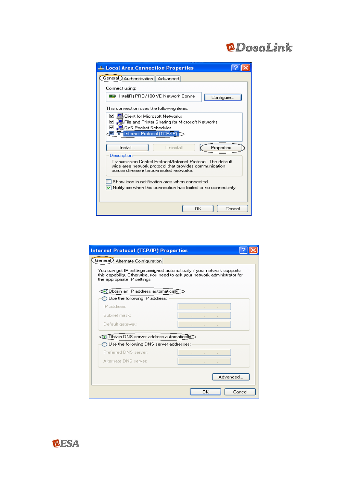
Figure 4 “Local Area Connection Properties” Window
Figure 5 “Internet Protocol (TCP/IP) Properties” Window
User’s Manual 11/73
Ver. [E.1.1]
6.1.2. Confirm and Renew the IP address
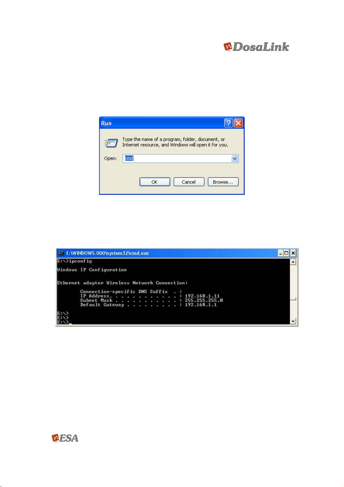
The saved configuration information may be confirmed by using the “ipconfig”
command in the DOS window.
1. Select “Start” => “Run” and input “cmd”. Then, click “OK” to execute the DOS
window.
Figure 6 “Run” Window
2. The IP address, Subnet Mask, and Gateway that are assigned automatically
should be confirmed with inputting the command “ipconfig” on the DOS
window. If it is normal, then the IP address should be assigned
“192.168.1.xxx” as shown in Figure 7.
Figure 7 DOS Window (“ipconfig”)
3. If the assigned IP address is outscope of “192.168.1.xxx, then it should be
renewed by “ipconfig /release” and “ipconfig /renew” commands as shown in
Figure 8.
User’s Manual 12/73
Ver. [E.1.1]
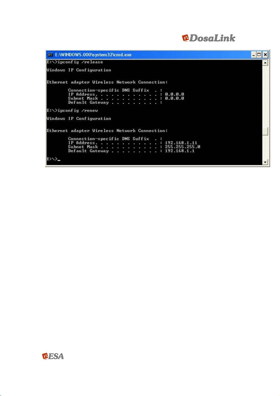
Figure 8 DOS WIndow (ipconfig / release & ipconfig / renew)
4. If the assigned IP address is an outscope of “192.168.1.xxx” or it has failed to
get an IP address even though the above steps for getting an IP address
were excuted, then the static IP address should be assigned by the user with
regard to the following section.
6.1.3. Assign the static IP address
This section explains how to assign the static IP address to the user’s PC when
the DosaLink – 540 cannot assign an IP address to the user’s PC or a server is
operating on the network.
1. “Control Panel” -> “Network Connections” -> “Local Area Connection” ->
“General” -> click “Properties”, and then Figure 9 pops up. In this “Local Area
Connection Properties” window, select “TCP/IP” and click “Properties”.
2. In the “Internet Protocol (TCP/IP) Properties” window, select “Use the
following IP address” and “Use the following DNS server addresses” as
shown in Figure 10. Then, input the correct addresses and click “OK” to save
the configuration.
User’s Manual 13/73
Ver. [E.1.1]

Figure 9 “Local Area Connection Properties” window
3. If several user’s PCs need to be assigned IP addresses, then the information
for Subnet Mask, Gateway, and DNS server should be the same and the IP
address should be selected between 192.168.1.2 and 192.168.1.254.
User’s Manual 14/73
Ver. [E.1.1]

Figure 10 “Internet Protocol (TCP/IP) Properties” window
7. Communication between user’s PC and the DosaLink – 540
The communication between the user’s PC and the DosaLink - 540 should be
confirmed before configuring the PC by utilizing the configuration window of the
DosaLink – 540. For this purpose the “ping” command can be used.
“Start” => “Run”, input “cmd” and press “OK”. The DOS window will be open.
Once performed “ping 192.168.1.1”, should appear as shown as Figure 11. If it
does not appear, then the sequence should be performed again after pressing
“reset”, which is located on the back of the DosaLink -540, and rebooting the
user’s PC.
User’s Manual 15/73
Ver. [E.1.1]
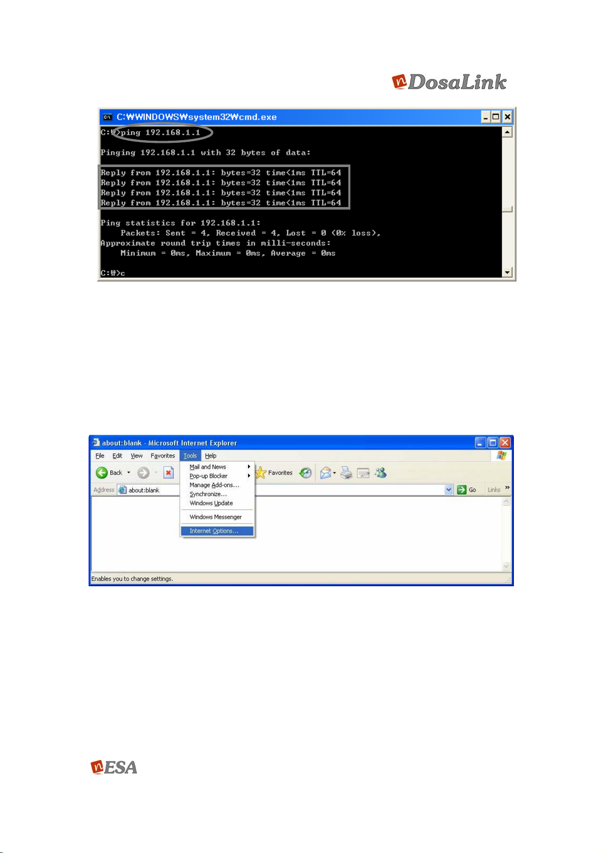
Figure 11 “ping” in the DOS window
8. Connect the Internet via the configuration window of DosaLink – 540
1. First, run the web browser to connect to the Internet. However, it is not
connected to the Internet because the DosaLink – 540 is not con figured yet. On
the web browser’s m enu, select “tools” => “Internet optio ns...”.
Figure 12 “Internet Option”
2. To Delete the temporary Internet Files in the Internet options window click on
“Delete Cookies...” and “Delete Files...” Then select “Connections”.
User’s Manual 16/73
Ver. [E.1.1]

Figure 13 “Delete Cookies” & “Delete Files”
3. At “Dial-up and Virtual Private Network settings” menu, select “Never dial a
connection” then click “LAN Settings...” as shown in Figure 14.
User’s Manual 17/73
Ver. [E.1.1]

Figure 14 “Dial-up and Virtual Private Network settings”
4. In the “Local Area Network (LAN) Se ttings” window, remove the check mark s (V)
as shown in Figure 15 and select “OK” to save the configurations.
User’s Manual 18/73
Ver. [E.1.1]

Figure 15 “LAN Settings” window
5. After configuration enter https://192.168.1.1 into the “Address” window of web
browser as shown in Figure 16.
Figure 16 https://192.168.1.1
6. Since the SSL is implemented to enhance the security, if th e message as show n
in Figure 17 appears, then select “Yes”.
User’s Manual 19/73
Ver. [E.1.1]

Figure 17. SSL Message
7. The Default “ID” and “Password” to connec t to this web page, shown in Figure
18, are ‘root’ and ‘admin’, respectively.
Figure 18 Default User ID and Password
8. If i t connects, as shown in Figure 19, the ini tial page to manage the D osaLink –
540 wil appear.
User’s Manual 20/73
Ver. [E.1.1]
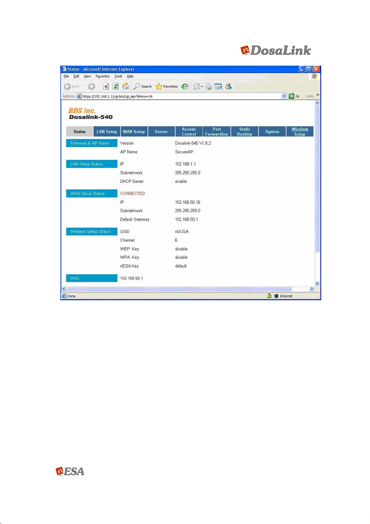
Figure 19 initial Page for DosaLink -540 Access Point
9. Configuration the DosaLink – 540
Since all configuration information is saved to the DosaLink – 540, automatically, it may
be necessary to configure only once from any user’s PC.
9.1. ADSL (PPPoE) users
In the case of the Automatic connection MODEM users among ADSL subscribers,
“Cable, VDSL” is selected for “Internet Service Type” in the “WAN Setup” menu.
1. Choose “ADSL (PPPoE)” for “Interne t Se rvic e Type” in the menu of “WA N Se tup” .
2. Input “User’s Name” and “Password”.
3. Click “Submit” to apply to the DosaLink – 540.
User’s Manual 21/73
Ver. [E.1.1]

4. Then, move to the “Status” menu and confirm and check the connection status.
Note) “MTU” means the maximum permissible packet size, which the default
value is 1440. This value may vary depending on the Internet Service Provider
(ISP).
Figure 20 Configuration Windows for ADSL Users
9.2. Cable and VDSL Users
1. The same as above, the Automatic connection MODEM users should select
“Cable, VDSL” for “Internet Service Type” in the “WAN Setup” menu as shown in
Figure 21.
2. Since most ISPs confirm the configured MAC address initially, as shown in
Figure 21, press “Clone” and the initial PC’s MAC address is appeared. Then,
click “Submit”.
“Restore” is for reconfiguring the factory default setting of user’s PC.
3. Click “Submit”, and the configuration is applied. Then, the PC will reboot with the
message on web browser.
User’s Manual 22/73
Ver. [E.1.1]

* After configuration, the status of the connection in the menu will be confirmed.
Figure 21 Configuration Windows for Cable & VDSL Users
9.3. Static IP Users
1. From the “WAN Setup” menu, select “Static IP”.
2. Input the IP address, Subnet Mask, Gateway, and DNS from your ISP.
3. Click “Submit”.
* After configuration, it will be confirmed by the “Status” window.
User’s Manual 23/73
Ver. [E.1.1]

Figure 22 Configuration window for Static IP Users
9.4. Remove all the Network related Programs(Daemons)
1. For configuring Dosalink-540 as simple Access Point like HUB device, select
“None”.
10. Network Connection Status
After configuration of “WAN Setup”, “LAN Se tup”, and “Wireless Setup”, theIP address
can be confirmed at the “Status” menu. As shown in Figure 23 below, the “WAN Setup
Status” indicates “Connected” and the addresses appear if it is connected to the Internet.
User’s Manual 24/73
Ver. [E.1.1]

Figure 23 Status Window
(1) Firmware & AP Name : Software Version for DosaLink – 540
(2) LAN Setup Status : LAN Setup Status
(3) WAN Setup Sta tus : Status of WAN Po rt and the Status for IP Add ress, Subnet
mask, and Gateway of WAN Port
(4) Wireless Setup Status : Wir eless Setup Status
(5) DNS : IP of DNS Server for WAN
11. DosaLink – 540 Menu Description
11.1. LAN Setup
1. The IP address and Subnet Mask’s range is configured in this menu. The
configured IP address is the Gateway of LAN Ports.
User’s Manual 25/73
Ver. [E.1.1]

2. If DHCP server is operating, then the IP address assigned to users connecting
the DosaLink – 540 should also be in the range of the con figured IP address in
this menu.
Figure 24 “LAN Setup” Window
11.2. Server
In this menu the related functions to DHCP and DNS are configured.
DHCP is the protocol that manages and assigns the IP address automatically. Thus, the
new IP address can be assigned to the user’s computer automatically w hen it connects
to the network, at anywhere in the network. However, in the case of using Web and FTP
servers, the static IP address should be used.
(1) In the menu of “DHCP Server”, select “Enable” or “Disable”.
If “Disable” is selected, then the “DHCP Relay Agent” should be selected as
“Enable” so that the client adapters are able to be assigned the IP address for
the server that connects to the DosaLink – 540.
If “Enable” is selected, then just configures “DHCP start and end Range” to
specify the range of the IP address.
(2) Configuration Domain Name Server (DNS)
“Real”: Use the DNS Server that is assigned by DHCP client or PPP. All DNS
query messages are transmitted to one of the DNS servers that are found
dynamically.
“Custom”: Use the configured DNS Sever. All DNS query messages are sent
to one of the DNS Servers that will be designated. The IP address of DNS
Server should be input.
User’s Manual 26/73
Ver. [E.1.1]
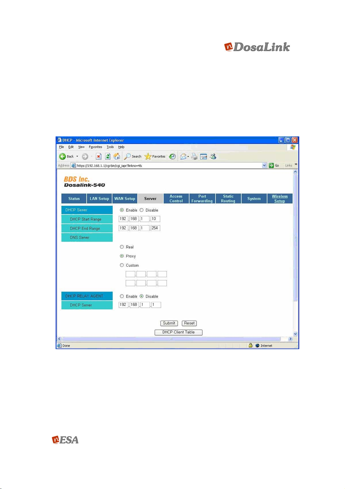
“Proxy”: The Gateway IP address of device is the DNS’ IP address.
(3) DHCP Relay Agent is the function that assigns the IP address to Local LAN or
WLAN’s Client from the DHCP Server, which connects to WAN. If it is configured,
then the requested DHCP from the Local PC transmits to the DHCP server over
the WAN. For this operation, NAT can be disabled and user should choose
“Disable” for DHCP function.
In the case of selecting “Enable”, the IP address for the DHCP should be
written into the menu as shown in Figure 25.
Figure 25 Configuration Window for “Server”
11.3. Access Control
This menu allows users to configure the access control to terminals that connect to the
DosaLink – 540. The configuration is established on the basis of the IP addresses that
are assigned to each terminal. This can be applied to a specific terminal for the access
control. It is able to restrict access of the output to a specific terminal from the DosaLink
User’s Manual 27/73
Ver. [E.1.1]
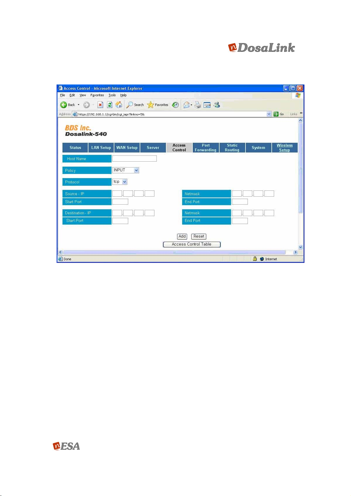
– 540, the input to the DosaLink – 540 from a specific terminal and the WAN or LAN
through the DosaLink – 540. In general, it is described as the function of IP Filtering.
Figure 26 Configuration Window for “Access Control”
(1) Host Name: A name for the terminal (PC) to be controlled. This is configured by
the user.
(2) Policy: Configure the Chain such as Input, Output, or Forward.
(3) Protocol: To restrict the specific protocols such as TCP and UDP. If it is
configured to “All”, then all protocols are blocked.
(4) Set the range for Source IP’s registration information Net Mask and Port of Input,
Output, and Forward in Policy.
(5) To register the information of Destination IP for the above (4).
(6) After the configuration above, click “Add”. It is then registered to the Access
Control Table. The user may confirm and delete the information that is registered
in the Access Control Table.
11.4. Port Forwarding
User’s Manual 28/73
Ver. [E.1.1]

To write the IP address of the PC to set the DMZ among the PCs that are connecting
to the LAN, select “Enable” and click “Submit”. To establish the DMZ that the
function operates as the same state, which does not utilize the firewall functionality of
the DosaLink – 540 by forwarding all the pac kets, connected to the of ficial IP that is
assigned to the DosaLink – 540 from the ou tside of the network, to the specific PC
that is connecting to the DosaLink – 540. If, at the specific PC, some special services
such as a Web Server and FTP Server are ab le to be operated by utilizing various
firewall functions that the DosaLink – 540 has, then it is possible for the external to
access to the DosaLink – 540 and impossible to access to the specific Programs of
PC that connects to the DosaLink – 540. In case that it is neces sary for the external
to forward to the specific program at the specific PC, the P ort Forwarding is used for
this purpose.
Figure 27 “Port Forwarding” Window
(1) Select “Enable” from the menu of “DMZ”. User can arbitrarily select the “Host
Name”.
(2) The IP address of the PC to be used as DMZ over the LAN is input. Then click
“Submit”. “Protocol” can be set to “TCP”, “UDP”, or “ALL”.
(3) To set the range of the specific Port Number, from the external.
(4) To input the IP address of the PC to which the specific Port is forwarding.
(5) To establish the range of Port Numbers to be used by the PC that is set in (4).
(6) Press “Add” to register the above setting into the “Port Forwarding Table”. If
“Reset” is pressed, the configuration is initialized.
* Click “Port Forwarding Table” to confirm the registered configuration.
User’s Manual 29/73
Ver. [E.1.1]

11.5.
Static Routing
Static Routing is the opposite of Dynamic Routing. It is the function that transfers the
data through the specific path. It is set in adva nce. The route can be configured with
regards to the IP address of the specific PC and the Gateway.
Figure 28 “Static Routing”
(1) To set the “Network Name” arbitrarily.
(2) To input the range of “Destination IP”, connecting to the intra network.
(3) To input “Subnetmask”.
(4) To input the “Gateway IP” of the “Destination IP” being used in the intra network.
(5) Press “Add”. Click “Reset” to initialize the configuration.
* Click the “Static Routing Table View” to confirm the registered configurstion.
11.6. System
This Menu offers various functions to manage the DosaLink – 540.
User’s Manual 30/73
Ver. [E.1.1]

Figure 29 “System” Window
(1) The “User ID” can not be modified and is used to connect to the configuration
window of DosaLink – 540.
(2) The “New Password”, used to modify the User Password, is used to connect to
the configuration window of DosaLink – 540. The default is “admin”.
(3) The “Factory Default” is used for resetting all the current configured values to the
initial values. When “Submit” is pressed, it is applied. The system should be
“Reboot”.
(4) The “System Rebooting” is to reboot the DosaLink – 540.
(5) The “Log Messages” shows the events that have occurred in the DosaLink – 540.
Its function can be helpful to manage the DosaLink – 540.
(6) The “System Firmware Upgrade” is used to upgrade the system software of
DosaLink – 540.
* Click “Browse”, and select the system software to be used for upgrading. Then,
press “Upgrade” to apply.
** The name of the system software should be “image.cramfs”.
User’s Manual 31/73
Ver. [E.1.1]

*** It takes about 3 min. to operate normally when upgrading. If “On/Off” power or
“Rebooting” of the DosaLink – 540 occurs while upgrading, it may cause fatal
damages to the DosaLink – 540.
(7) The “nESA EDATA UPLOAD” is used to modify the Data that is related the nESA
– the enhanced wireless security function is offered by the DosaLink – 540. The
uploaded “EDATA”, supporting the nESA, may not be deleted even if “Factory
Default” is applied.
** The file name of the “EDATA” should be “edata.str”.
11.7. Wireless Setup
This Menu guides users to set the basic wireless configuration for the DosaLink –
540. Users can establish and operate the WEP, the basic WLAN security of the IEEE
802.11 standards, in this menu.
Figure 30 Wireless Setup
User’s Manual 32/73
Ver. [E.1.1]

(1) The “AP Name” is for naming the DosaLink – 540. It can be any name the user
chooses to manage the AP.
(2) The “Operation Mode” is for defining the application of DosaLink – 540.
Select “AP” for using DosaLink – 540 as the Access Point.
If the DosaLink – 540 is used for the Wireless Bridge such as the Point-to-Point
(PtP) and Point-to-MultiPoint (PMP), then select either “Wireless Bridge (Master)”
or “Wireless Bridge (Slave)”. If it is connected to the Internet or upper layer
network, then select “Wireless Bridge (Master)”. If it is connected to the wireless
master bridge for relaying the network, then select “Wireless Bridge (Slave)”.
In the case of Wireless Bridge, the “Using WDS” should be enabled and the MAC
Addresses of DosaLink – 540 to be connected should be registered in the Menu
of “WDS”. Therefore, the client adapters can not be connected to the DosaLink –
540 that is set to “Wireless Bridge”.
(3) The “Country Code” can not be modified from what is set in the DosaLink – 540.
Frequencies for each country are different.
(4) The “SSID” is an abbreviation for Service Set Identifier. It is a 32 byte character
unique identifier attached to the header of packets sent over a WLAN. The “SSID”
between the DosaLink – 540 and the user’s PC should be the same.
It should use the alphabet or the number. In case of the alphabet, it should be
distinguished between the lower and upper case.
(5) IEEE 802.11 Standards are selected in this menu – “Wireless Mode Selection”. For
instance, if “802.11g only” is selected, then its users only connect. In case of
selecting “802.11b+g mixed”, since the users of 802.11b are able to connect, it may
cause a slow transmission speed for the users of 802.11g. Also, if “802.11a only” is
selected, then its users only connect.
(6) The “Channel Select” menu is for channel selection methods of the DosaLink – 540.
The DosaLink – 540 supports the selection of either “Manual” or “Auto” for the
method of channel selection.
When “Manual” is selected, the channel in “Channel Number” is set. When “Auto”
is selected, the channel that has good signal strength and receiving sensitivity is
selected automatically from all possible channels. In the case of selecting “Auto”
of 802.11a standard, if the chosen channel in “Channel Number” is the one of
channels of 802.11a, then it will be selected automatically among the possible
channels of 802.11a.
(7) The “Channel Number” menu is only available when the “Channel Select” is set to
“Manual”.
Channel 6 is the Factory Default value.
(8) The WEP can be selected in the “WEP” menu.
If the WEP, an encryption to protect the data over the wireless area, is selected
“Enable”, then the user’s PC to connect to the DosaLink – 540 should also be set
with the same WEP information as in “Key length”, “Authentication Type” and
“KEY”(64bit, HEX or Passphrase).
User’s Manual 33/73
Ver. [E.1.1]

(9) When the WEP is “Enable”, the user can also select the key length of WEP
according to the following Table. (The encryption key can be made of the number (0
~ 9) and the alphabet (A ~ Z)).
Key Length
Number Code
ASII HEX
64 bits 5 Char. 13 Char.
128 bits 10 Char. 26 Char.
(10) The menu “Authentication Type” is three different types of authentication of the
wireless device.
“Open System”: All users’ PCs, with the corresponding channel information, are
able to connect to the DosaLink – 540.
“Shared Key System”: Only the users’ PCs with the corresponding channel
information and WEP key can connect to the DosaLink – 540.
“Both System”: Is controlled automatically. All wireless equipment should be
using the same authentication method.
The basic setting is “Open System”.
(11) There are 4 keys for the WEP.
(12) The stored WEP key should be selected.
(13) For configuring WEP with “Passphrase”, input narative sentence in the box of
“Passphrase” (ex: I am a boy). There is no required grammar of the sentence.
11.8. nESA Setup
The WLAN, communicating over a wireless medium, is vulnerable in nature. For that,
the IEEE802.11 Task Group (TG) has generated the various security solutions such
as WEP, WPA, WPA2, 802.1x, and etc. However, it has been reported that these
technologies are not enough to cure the weakness of WLAN. Its security vulnerability
has made users’ obstacles adapt to the WLAN system. To resolve the security issue
of WLAN is to hide the WLAN network from the outside and to encrypt all the data,
transmitted and received over the WLAN network.
The nDosa Enhanced Security Algorithm (nESA) developed by nDosa Technologies
Inc. is the only security solution that makes the WLAN network invisible. The
DosaLink – 540 is equipped with the nESA technology and this menu leads the user
to configure the nESA. All the information that is set in this menu should be
established at the user’s PC to be connected to the DosaLink – 540. In addition to
the nESA technology, there is the novel key management system, called
LinkAuthentica, for the enterprise users.
The features of LinkAuthentica are summarized as follows:
The novel concept of the key management system for the nESA security keys
does not have the problems that the Pre-Shared key method has.
User’s Manual 34/73
Ver. [E.1.1]

Each user on the same subnet is assigned a unique user key which is
different from the other users.
Since each user’s key is not compatible with other users’, it is not a concern if
it is lost.
Strong security and excellent flexibility can be offered to the user.
LinkAuthentica is composed of two parts – Key Generator and Client
Manager.
- Key Generator: Generates the Master Key and the unique user key for
each user on the same subnet.
- Client Manager: The program, resides on the client adapter, generates a
Master Key by using the unique users keys that the Key Generator
generates and the user inherent information so that the client adapter can
be connected to the DosaLink – 540.
* The Master Key is not revealed outside or transmitted over the network.
* Please refer to the LinkAuthentica User Manual for more information.
Figure 31 nESA Set
(1) There are 4 different selections to operate the nESA in the menu “nESA
Key Type”.
Disable: The nESA is not used.
Default Key: It means the Factory Default. It is not necessary for theuser
to input the key.
User Key: The user should input 64 Hex numbers for the nESA key into
“User Key” or “Passphrase”.
User’s Manual 35/73
Ver. [E.1.1]

LinkAuthentica: This selection, the nESA Key Management System, is for
the enterprise customers.
(2) If the “User Key” is selected in the “nESA Key Type”, then the user should
input the key into this menu and click “Submit”.
(3) If the “LinkAuthentica” is selected in the “nESA Key Type”, then using
“Browser…” searches for the related key file (the file name should be
“linkA_AP.key”) and click “Upload”. And then click “Submit” toactivate the
key. The file “linkA_AP.key” can be generated by the LinkAuthentica Key
Generation program. Please refer to the LinkAuthentica User’s Manual for
more information.
(4) The menu, “Passphrase”, generates the key automatically with inputting a
user specific word or phrase. If the user wants to generate the WEP key
manually, then this menu should be blanked. First, input user specific
ASCII into the menu and click “Key_Generation, then it is generates the
key automatically and applies the key to the system. Second, click “Submit”
to activate the setting.
11.9. Advanced
Figure 32 Advanced
(1) The transmitting power of the system can be controlled in this menu, “Tx Power
Control”. There are 4 different steps to control – “AUTO, 100%, 70% and 50%”.
(2) The transmitting data rate can be controlled in the menu of “Tx Rate” at 1 ~ 54
Mbps and AUTO.
User’s Manual 36/73
Ver. [E.1.1]

(3) The permissible packet size over wireless medium is defined in this menu –
“Fragmentation Threshold”. The packet size of 2346 is recommended. If the
fragmentation packet error rate is high, a fragmentation threshold of between 256
and 2346 can be controlled gradually. If the “Fragmentation Threshold” is
established too low, then the communication performance may be poor.
(4) The frame size is set in this menu – “RTS Threshold”. There are two signals
(Request-to-send (RTS) and Clear-to-send (CTS)) to control the WLAN
communication. The recommended value is 2437. If the communication flow is
not smooth, then use this menu to control the “RTS Threshold” between 0 and
2437.
(5) The “Beacon Period” controls the interval of Beacon Frame that is generated
from the DosaLink – 540. The default value of 100 is recommended.
(6) The number of Beacon Interval in the Delivery Traffic Indication Message (DTIM)
is defined in this menu – “DTIM Interval”. It can be set between 1 and 255.
11.10. Wireless Distribution System (WDS)
The WDS function is established in this menu.
The WDS is the function that the DosaLink – 540, is connecting the Ethernet,
connects to the other DosaLink – 540, is not connecting the Ethernet, in the same
subnet so that the data traffic that is from the DosaLink of not connecting the
Ethernet relays to the DosaLink – 540 that is connecting to the Ethernet. It is
possible to set the links between six of the DosaLink – 540 in max. The user’s PC
can be connected to any DosaLink – 540 that connects in WDS. The wa ys to se t the
WDS between the DosaLink – 540s that are able to extend a WLAN network in the
same subnet are the Point-to-Point (PtP) and the Point-to-Multipoint (PMP).
(1) The menu of “WDS” is for the selection of use of the WDS. If the “Wireless
Bridge (Master or Slave)” is selected in the 10.7 – “Wireless Setup”, then it
should also activate the WDS.
(2) The “MAC Address 1 ~ 6” is for the MAC Ad dress of the Do saLink – 540s, which
may be connected by the DosaLink – 540 that is activated for WDS or Wireless
Bridge (Master or Slave).
User’s Manual 37/73
Ver. [E.1.1]

Figure 33 WDS
11.11. MAC Filtering
The user’s PC has its own unique MAC Addres s. Access to the DosaLink – 540 can
be controlled based on this information.
(1) The access control of DosaLink – 540 based on the MAC address of the user’s
PC is established in this menu – MAC Filtering.
Disable: Do not use the MAC Filtering
Accept: Only the user’s PC with a MAC address that is listed in the MAC
Filtering Table are able to access the DosaLink – 540.
Deny: The user’s PC with a MAC address that is listed in the MAC Filtering
Table are denied access to the DosaLink – 540.
(2) The new MAC address that is registered to the MAC Filtering Table is set in this
“MAC Address” menu. The registered MAC addresses can be confirmed by
clicking the “MAC Filtering Table”.
User’s Manual 38/73
Ver. [E.1.1]

11.12. IEEE 802.1x
Figure 34 MAC Filtering
The IEEE 802.1x is the standard Port Access Protocol that authenticates the user via
the Radius Authentication Server. By using the information from the user’s PC
(Authenticator, ID, Password, etc.) it is authenticated to control access to a wireless
network. For these procedures, the Extensible Authentica tion Protocol (EAP) is use d
between the Radius Authentication Server and the user’s PC in the s tandard of IE EE
802.1x. The information from the user’s PC, passing through the EAP, can be
verified by the Radius Authentication Server. Depending upon its verification it
should decide to connect to a wireless network. Depending upon the types and
results of the authentication the Dynamic U nicast Session Key or Static Broadcast
Key which the IEEE 802.1x EAP packets contain is transferred to the authenticated
user’s PC. The Session Key can be different for each authenticated user’s PC. This
information can be utilized to encapsulate the data that are between the DosaLink –
540 and the authenticated user’s PC.
The DosaLink – 540 supports the following authentications:
• EAP-MD5 (Message Digest): This type of EAP authentication offers the basic
level of EAP. User ID and User Password of the user’s PC are used for
authentication. Since MD5 algorithm is used one-way harsh function, the
authentication between the user’s PC and the Radius Authentication Server
is processed one-way.
• EAP-TLS (Transport Layer Security): EAP-TLS provides for mutual
authentication based on the certificates between the user’s PC and the
Radius Authentication Server. The keys for authentication are generated
dynamically.
User’s Manual 39/73
Ver. [E.1.1]

• EAP-TTLS (Tunneled Transport Layer Security): EAP-TTLS is the protocol
that improved EAP-TLS. It provides for mutual authentication and generation
of dynamic user’s or sessions secret keys based on the certificates between
the user’s PC and the Radius Authentication Server via the encrypted
channel (or the tunnel). EAP-TTLS requires only the Radius server-side
certificates.
The DosaLink – 540 supports the Web Redirection.
When the user’s PC that connects to the DosaLink – 540 fails to authenticate, it
allows the user’s PC to point the specific WEB Site.
Figure 35 802.1x
(1) Select IEEE 802.1x authentication function in the menu of “802.1x”.
(2) Input an IP address of the Authentication server into the menu of “Authentication
Server IP1”. The Port number that associates with the Authentication Server
should be written into “Port”. The default value is 1812.
(3) The “Shared Secret” is a text string that serves as a password, registered at the
authentication server. It must be the same “Shared Secret” between the
authentication server and the DosaLink – 540.
User’s Manual 40/73
Ver. [E.1.1]

(4) An IP address of the accounting server should be written into the menu of
“Accounting Server IP1”. The Port number that is associated with the accounting
server should be input into this menu. The default value is 1813.
(5) The “Shared Secret” is a text string that serves as a password, registered at the
accounting server. It must be the same “Shared Secret” between the accounting
server and the DosaLink – 540.
(6) This menu is for the second authentication server, accounting server, port
numbers, and shared secrets. If there is not a second choice, then it may be
blanked.
(7) In the “RETRY_PRIMARY_INTERVAL” the time interval when it is requested to
connect to the second authentication server after failing to authenticate from the
first authentication server is established in the case of using a couple of
authentication servers.
(8) The time from failing to authenticate to requesting to reauthenticate is set in this
menu of “ACCT_INTERIM_INTERVAL”.
(9) WEB_REDIRECTION: Select to use the Web Redirection function in this menu.
(10) WEB_REDIRECTION_IP: Input the IP address of Web site that is to be
connected automatically when IEEE 802.1x authentication is failed.
The function of Web Redirection is associated with MD5 of IEEE 802.1x.
When the function of Web Redirection is activated, the message for re-booting
the DosaLink – 540 appears. Click “OK” to re-boot the DosaLink – 540. After this,
the function of Web Redirection can be used.
11.13. Wi-Fi Protected Access (WPA)/ WPA2 (IEEE 802.11i)
The DosaLink – 540 is offered the following two modes:
WPA and WPA2: It is associated with IEEE 802.1x so that the user’s PC is
authenticated and its keys are distributed to the authenticated user’s PC. The
Radius Authetication Server is needed and either the EAP-TLS or the EAPTTLS, are used to authent icate.
WPA-PSK and WPA2-PSK: The Pre-Shared Key (PSK) mode is not used
that Radius Authentication Server and associated with IEEE 802.1x. The PSK
that is formed, either 256 bits – 64 hexadecimal or 32 alphanumeric
characters, is inputed directly by a user.
User’s Manual 41/73
Ver. [E.1.1]

Figure 36 WPA
(1) Select to use the WPA in the menu of “Using WPA”.
(2) The menu of “Authentication Type” selects to use either WPA-PSK or
WPA-EAP when the WPA is enabled.
(3) If the WPA-EAP is selected, then the Radius Server’s IP address, Port,
and Shared Secret are written into this menu – “Radius Server”.
(4) Select to use either “AES” or “TKIP” in this menu – “Cipher Suite”.
(5) Select to use either “Passphrase” or “Hexa” in the “Pre-Shared Key
Format” if the WPA-PSK is selected.
(6) Input the keys in format – “Pre-Shared Key”.
User’s Manual 42/73
Ver. [E.1.1]

Input 8 – 63 characters if the “Passphrase” is selected.
Input 64 chracters if the “Hexa” is selected.
(7) The menu of “Using RSN/WPA2” is for selecting to use of WPA2.
(8) This is same as (2).
(9) Select to use of the “Preauth” function.
(10) Establish the “Preauth Life Time”.
(11) This menu is same as (3).
(12) This menu is same as (4).
(13) This menu is same as (5).
(14) This menu is same as (6).
(15) Establish the “Rekey Time”.
(16) Set the “Rekey Packets”.
(17) Set the “Reauth Time”.
11.14. Virtual Local Area Networks (VLAN)
A virtual LAN (VLAN) is a method of creating independent logical networks within a
physical network. Several VLANs can co-exist within such a network. Th is helps to
reduce the broadcast domain.
A VLAN consists of network computers and dev ices that exist on the same do main.
They may actually be physically connected to different segments of a LAN. The
network administrator configures VLANs through software rather than hardware,
which makes them flexible.
The VLAN technology is applied to the WLAN networks by using the IEEE 802.1q
tagging protocol.
The DosaLink – 540 supports the Port base VLAN. For the purpose of using this
function, the wired network connecting to the Dos aLink – 540 should be segemented
by the VLAN and it should be consisted of switches, routers, DHCP Server, and
Radius Authentication Server that are supporting the network.
User’s Manual 43/73
Ver. [E.1.1]

Figure 37 VLAN
(1) Select to use the VLAN.
(2) The authenticated client’s VLAN ID value is set in this menu – “Authenticated
VLAN ID” (2 ~ 4095).
(3) The unauthenticated client’s VLAN ID value is set in this menu –
“Unauthenticated VLAN ID” (2 ~ 4095).
12. Factory Resetting
The Factory Resetting means to set the configuration of DosaLink – 540 as the initial
values.
The most recent uploaded EDATA via “nESA EDATA UPLOAD” should be
maintained even though the Factory Resetting is performed.
12.1. Resetting via the Web
(1) Go to the configuration window of DosaLink – 540 (https://192.168.1.1). Refer
to the menu – “Connecting the Internet via the configuration window of
DosaLink – 540.
(2) Press the “Submit” of “Factory Default” in the below Figure 38.
User’s Manual 44/73
Ver. [E.1.1]
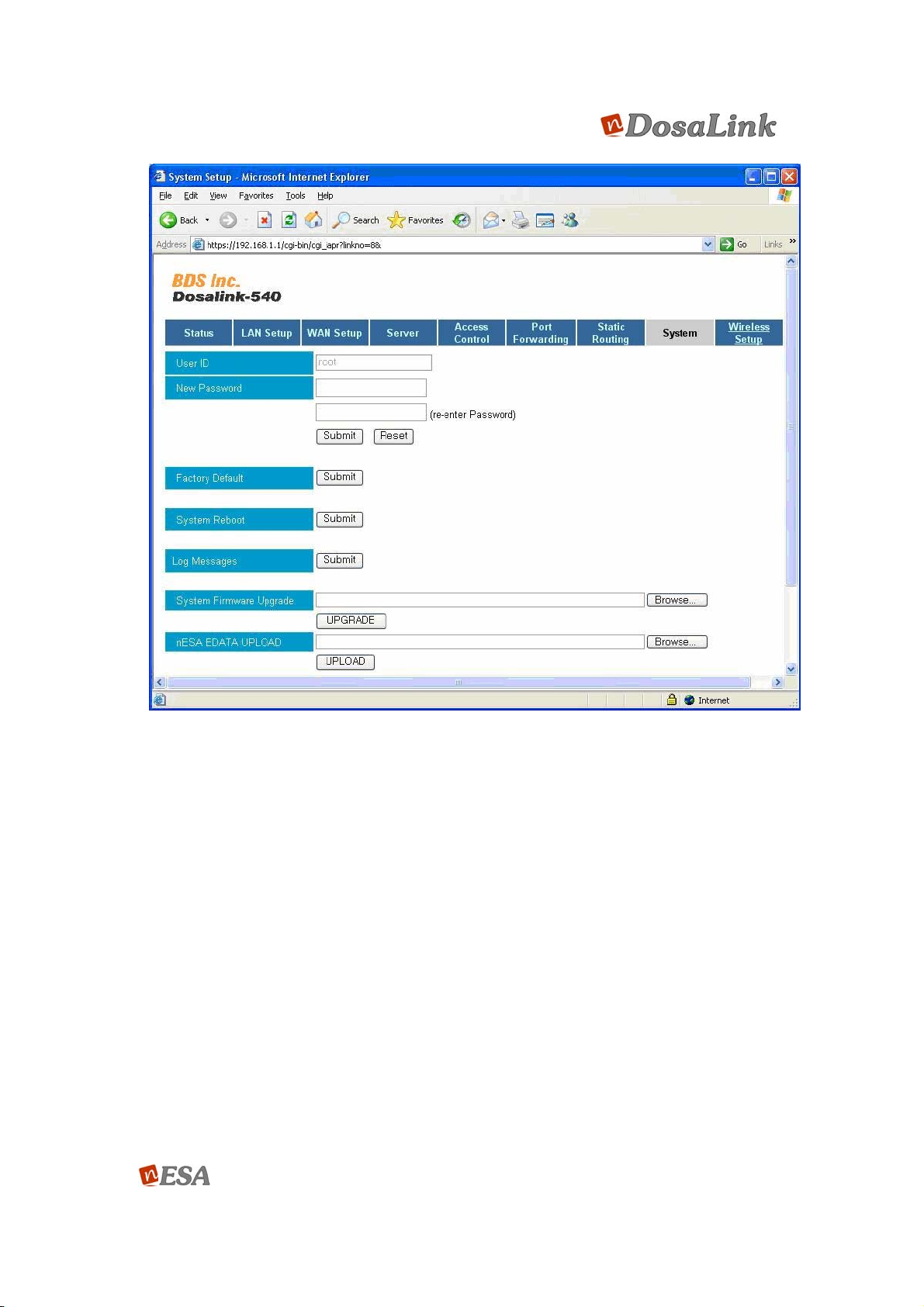
Figure 38 System
(3) When Fgure 39 appears, press “OK” to return the previous display.
The DosaLink – 540 reboot after changing to the Factory Default.
User’s Manual 45/73
Ver. [E.1.1]

Figure 39 Result Page
(4) If the “Submit” of “System Reboot” in Figure 40 is pressed, then it has
completed the Factory Resetting with rebooting the DosaLink – 540.
User’s Manual 46/73
Ver. [E.1.1]

Figure 40 System
12.2. Hardware Reset
If the Reset Button, located in the back of DosaLink – 540, is pressed for 5 seconds,
then all the configuration values are back to the Factory Resetting. Approximately
one or two minutes is needed to reboot the DosaLink – 540 automatically.
13. Configuration via Console
Refer to “Menu Descriptions of DosaLink – 540” section for detailed descriptions of
the functions.
13.1. Connection
1. Connecting “telnet” in the Dos window.
User’s Manual 47/73
Ver. [E.1.1]

Figure 41 connecting telnet
2. Input “login ID” and “Password” (the defaults are “root” and “admin”, respectively).
Figure 42 Login
User’s Manual 48/73
Ver. [E.1.1]

3. This is the initial display of connecting Console.
1. Status: Shows the current configuration status of DosaLink – 540.
2. LAN Setup: Input the LAN IP address.
3. WAN Setup: Select the method to connect to WAN and configure it.
4. Sever: Select and set the DHCP Server and DHCP RELAY AGENT.
5. Access Control: Set the firewall functions by using the IP addresses.
6. Port Forwarding: Establish the DMZ and Port Forwarding functions.
7. Static Routing: Configure the communication paths.
8. System: Confirms modifying Password, Factory Resetting, etc.
9. Wireless Setup: Set the basic wireless configuration.
13.2. Status
Figure 43 Initial Display for connecting Console
User’s Manual 49/73
Ver. [E.1.1]

Figure 44 Status window
(1) F/W Version: Shows the Firmware Version of DosaLink – 540.
(2) LNA Status: The configured LAN IP, Subnetmask, and use of DHCP Server
are confirmed in this menu.
(3) WAN Status: Shows the status of WAN, WAN IP Address, Subnetmask,
Default Gateway.
(4) Wireless Status: Shows SSID, current Channel, nESA Key setting, etc.
(5) DNS: Shows the information for DNS.
13.3. LAN Setup
User’s Manual 50/73
Ver. [E.1.1]

Figure 45 LAN Setup
1. IP: LAN IP address is shown. It can be changed. If the IP address is modified, a
communication currently connected with the user’s PC is disconnected.
2. NetMask: The NetMask is set in this menu.
3. s. save: Register the newly configured information.
4. r. return: Back to the previous display.
13.4. WAN Setup
The connection method for WAN is selected and configured in the WAN Setup
(Default is “Cable/VDSL”).
User’s Manual 51/73
Ver. [E.1.1]

Figure 46 WAN Setup
If PPPoE (ADSL) is used, then select 1. PPPoE Setup in Figure 47.
Figure 47 PPPoE Setup
1. Select “1”, which is “User Name” and input ID (User Name), is registered at ISP.
User’s Manual 52/73
Ver. [E.1.1]

Figure 48 PPPoE Setup
2. Select “2” – “Password” and input the Password that is registered at ISP.
3. The value of “MTU” may be modified as shown in figure 48 above.
4. Save the configured values.
If Cable or VD SL is used, then select “2. Cable/VDSL Setup” from the “WAN
Setup”. If the DHCP server is operated, it is also established via “Cable/V D SL
Setup”. An ISP controls access to the network from clients based on the
client’s MAC Address. If it is needed, then the MAC clone function should b e
utilized to access the network.
User’s Manual 53/73
Ver. [E.1.1]

Figure 49 Cable/ VDSL Setup
(1) Select “MAC Address” and change the Mac address.
Figure 50 MAC Address
(2) If the previous MAC Address needs to be restored, then select
“Restore MAC Address”.
User’s Manual 54/73
Ver. [E.1.1]

If the s tatic IP address is used, then select “3. Static Setup” from the “WAN
Setup”.
Figure 51 Static Setup
Input IP Address, NetMask, GateWay Address, and D NS Server IP which
(1)
are assigned to the DosaLink – 540.
13.5. Server
This is for setting the DHCP Server. The basic settings in this menu are the DHCP
Server Enable and DHCP RELAY AGENT Disable. Both the DHCP Sever and DHCP
RELAY AGENT are not to be set to “Enable” at the same time.
User’s Manual 55/73
Ver. [E.1.1]

Figure 52 Server Setup
(1) 1. DHCP Server Setup: Configure the DHCP Server.
Figure 53 DHCP Server Setup
(1) DHCP: Select to use the DHCP Server.
(2) Start Addr and End Addr: Specify the assigned range of IP for the DHCP
Server.
User’s Manual 56/73
Ver. [E.1.1]

(3) DNS Server: Configure DHCP Server
The default is “Proxy” so that AP is operated as Proxy Server.
(4) DNS Addr1 and DNS Addr2: If the configuration of DNS Server is not Proxy,
then IP address should be input to DNS Server.
(5) DHCP Client Table: The registered information of DHCP Client Table may
be confirmed.
(2) 2. DHCP Relay Setup: Configure DHCP Relay Agent.
Figure 54 DHCP Relay Setup
(1) DHCP Relay: Select either “enable” or “disable”.
(2) DHCP Server: Input the IP address that connects to the WAN port of
DosaLink – 540.
* In case of selection of DHCP Relay, the “DHCP” of “DHCP Server” must be set
“Disable”.
13.6. Access Control
This is for setting the Firewall by using IP Filtering function.
User’s Manual 57/73
Ver. [E.1.1]

Figure 55 Access Control Setup
1) Host Name: Arbitrary Name (No space).
2) Policy: Select among Input/ Output/ Forward
3) Protocol: Select the specific protocols, for example TCP/UDP, to be
controlled. If it is configured to “All”, then all protocols are controlled.
4) Set the range for Source and Destination IP regis tration information, Net
Mask, Port of Input, Output, and Forward in the “Policy”.
Source IP: 0.0.0.0 for every available IPs.
Src NetMask: 0.0.0.0
Src Start Port and Src End Port: The specified ranges for Port
can be assigned. If no address is input, then it is for all Ports.
Destination IP: Is for WAN IP of AP.
Dest NetMask: May not need any input.
Dest Start Port and Dest End Port: May not need any input.
5) Print: Allows user to confirm and delete the information that is configured.
13.7. Port Forwarding
Configure the DMZ to the specific PC and the Port Forwarding to the specific Port.
User’s Manual 58/73
Ver. [E.1.1]

Figure 56 Port Forwarding Setup
1) DMZ Setup
Figure 57 DMZ Setup
(1) DMZ: Select either “enable” or “disable”.
(2) IP Address: Input the IP address of the user’s PC to be configured.
User’s Manual 59/73
Ver. [E.1.1]
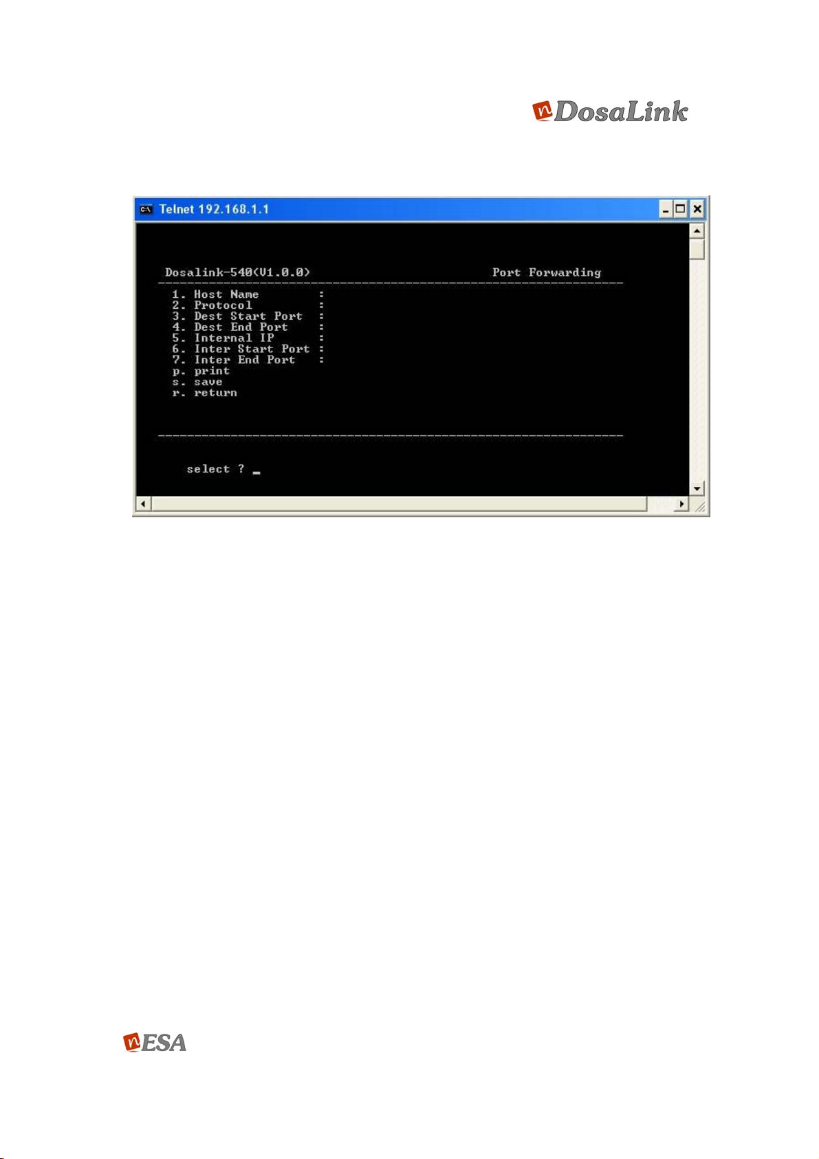
2) Port Forward
Figure 58 Port Forward Setup window
(1) Host Name: Choose the name arbitrarily.
(2) Protocol: Can be set to TCP, UDP, or ALL.
(3) Dest Start Port/ Dest End Port: Set the range of the specific Port Number,
from the external.
(4) Internal IP: Input the IP address of PC to which the specific Port is
forwarding.
(5) Internal Start Port/ Internal Stop Port: Establish the range of Port Numbers
to be used by the PC that is set in (4).
(6) P: Confirm the information that is registered at the Port Forwarding Table.
13.8. Static Routing
User’s Manual 60/73
Ver. [E.1.1]

Figure 59 Static Routing Setup
1) Network Name: Set the “Network Name” arbitrarily.
2) Destination IP: Input the range of “Destination IP”, connecting to the intra
network.
3) Subnet Mask: Input “Subnet Mask”.
4) GateWay: Input the Gatway IP (WAN IP), as used in the intra network.
5) p: Confirm the registered configuration at the Static Routing Table.
13.9. Wireless Setup
This section outlines how to set the wireless configuration for the DosaLink – 540.
User’s Manual 61/73
Ver. [E.1.1]

Figure 60 Wireless Setup
1. Primary Setup: Set to the basic configuration for WLAN such as SSID, Channel,
WEP Key, nESA Key, etc.
2. Advanced Setup: Set to the advanced configuration for WLAN such as Tx Power,
Rate, Threshold values, etc.
3. WDS: Set to the communication path between one DosaLink – 540 and another
DosaLink – 540 via WDS configuration.
4. MAC Filtering: Can be controlled to access the Dos aLink – 540 based on the MAC
address of user’s PC.
5. 802.1x setup: Control access from user’s PC by associating with the Radius
Authentication Server.
6. VLAN Setup: Configure to cooperate with the wired network which VLAN is
structured.
13.9.1. Primary Setup
User’s Manual 62/73
Ver. [E.1.1]

Figure 61 Primary Setup
1. AP Name: For naming the DosaLink – 540. User can select any name that will be
easy to manage.
2. Operation Mode: Is for defining the application of DosaLink – 540. If the DosaLink –
540 is used as AP, then select AP. If the DosaLink – 540 is used for the Wireless
Bridge such as the Point-to-Point (PtP) and Point-to-MultiPoint (PMP), then select
either “Wireless Bridge (Master)” or “Wireless Bridge (Slave)”. If it is connected to the
Internet or upper layer network, then select “Wireless Bridge (Master)”. If it is
connected to the wireless master bridge for relaying the network, then select
“Wireless Bridge (Slave)”. In the case of the Wireless Bridge, the WDS should be
enabled and the MAC Addresses of DosaLink – 540 should be connected and
registered in the Menu of “WDS”. Thus, the client adapters can not connected to the
DosaLink – 540 that is set to “Wireless Bridge”.
3. Country Code: This can not be modified from what is set in the DosaLink – 540.
Each country’s frequency is different.
4. Wireless Mode: IEEE 802.11 Standards are selected in this menu – “Wireless Mode
Selection”. For instance, if “1” is selected, then 802.11g users only connec t. In case
of selecting “0”, since the us ers of 802.11b are able to connect, it may cause a slow
transmission speed for the users of 802.11g. If “2” is selected, then 802.11a users
only connect.
5. SSID: Is a 32 byte character unique identifier at tached to the header o f pa ckets sent
over a WLAN. The “SSID” between the DosaLink – 540 and the user’s PC sho uld be
the same. It should use the alphabet or the number. When using the alphabet, it
should be distinguished between the lower and upper case.
6. Channel Select: The “Channel Select” menu is for channel selection methods of the
DosaLink – 540. The DosaLink – 540 supports the selection of either “Manual” or
User’s Manual 63/73
Ver. [E.1.1]
“Auto” for the method of channel selection. When “Manual” is selected, the channel
in 7 Channel Number is set. When “Auto” is selected, the channel that has good
signal strength and receives sensitivity is selected automatically from all possible
channels. In the case of selecting “Auto” of 802.11a standard, if the chosen channel
in 7 Channel Number is one of the channels of 802.11a, then it can be selected
automatically among the possible channels of 802.11a.
7. Channel Number: The “Channel Number” is only available when the “Channel
Select” is set to “Manual”. The Channel 6 is the Factory Default value.
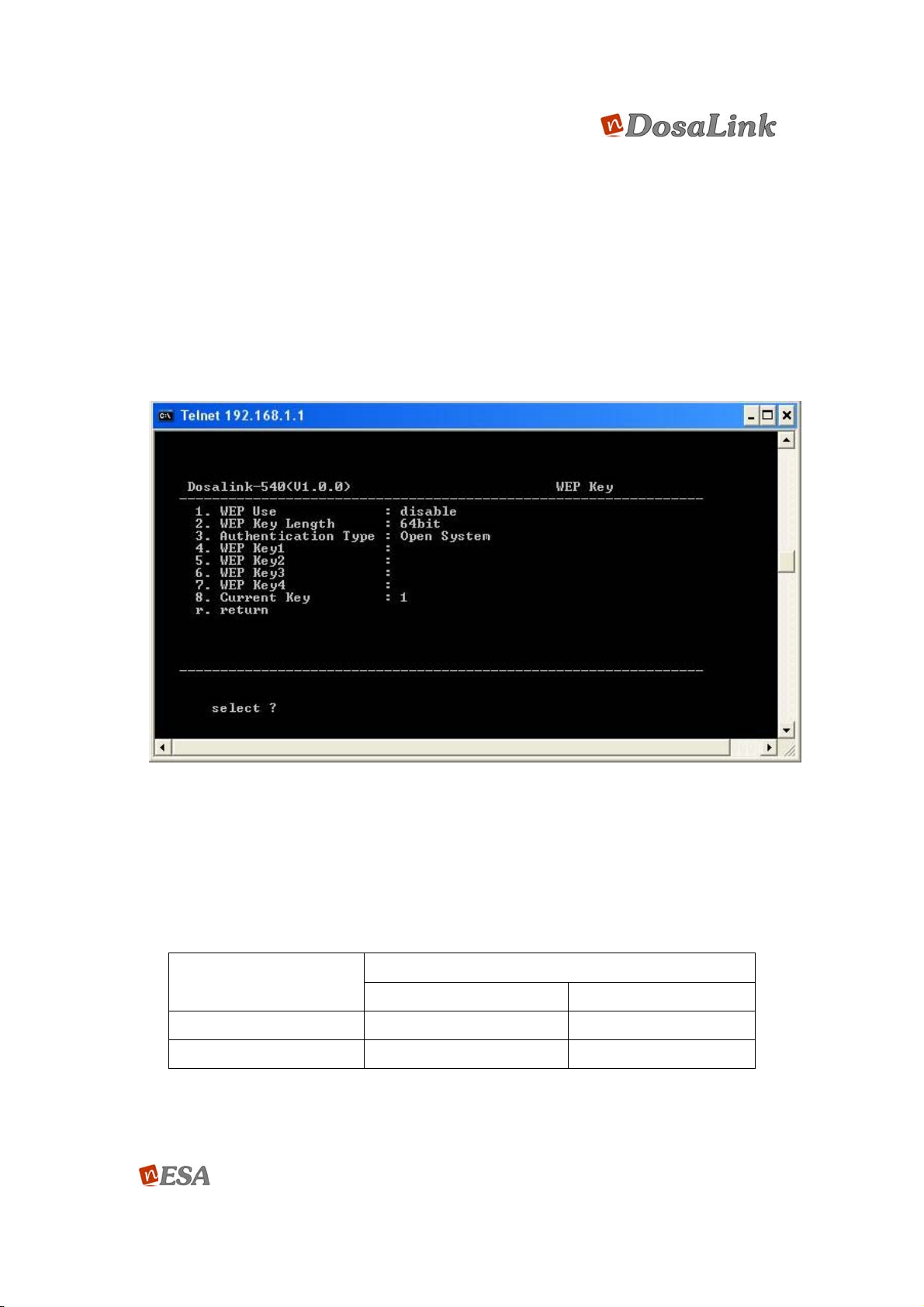
8. WEP Key Setup: If the WEP, an encryption to pro tect the da ta over the wireless are a,
is selected “Enable”, then the user’s PC to connect to the DosaLink – 540 should
also be set to WEP with the same information.
Figure 62 WEP Key Setup
(1) WEP Use: Select either “enable” or “disable”.
(2) WEP Key Length: When the WEP is selected “enable” in “WEP Use”, the
user can select the key length of WEP from the following Table. (The
encryption key can be made of numbers (0 ~ 9) and the alphabet (A ~ Z)).
Key Length
ASII HEX
64 bits 5 Char. 13 Char.
128 bits 10 Char. 26 Char.
(3) Authentication Type: There are three different types of authentication of the
wireless device.
Number Code
User’s Manual 64/73
Ver. [E.1.1]

“Open System”: All users’ PCs with corresponding channel information,
are able to connect to the DosaLink – 540.
“Shared Key System”: Only users’ PCs with corresponding channel
information and WEP key can connect to the DosaLink – 540.
“Both System”: Is controlled automatically. All wireless equipment should
use the same authentication method.
The basic setting is “Open System”.
(4) There are 4 keys for the WEP.
(5) The stored WEP key should be selected.
13.9.2. Advanced Setup
Figure 63 Wireless Advance Setup
(1) Tx Power Control: The transmitting power of the system can be controlled in this
menu, “Tx Power Control”. There are 4 different settings – “AUTO, 100%, 70% and
50%”.
(2) Tx Rate Control: The transmitting data rate can be controlled at 1 ~ 54 Mbps and
AUTO.
(3) Fragmentation Threshold: The permissible packet size over wireless medium is
defined. The packet size of 2346 is recommended. If the fragmentation packet error
rate is high, a fragmentation threshold between 256 and 2346 can be controlled
gradually. If the “Fragmentation Threshold” is established too low, then the
communication performance may be poor.
(4) RTS Threshold: The frame size is set in this menu – “RTS Threshold”. There are
two signals (Request-to-send (RTS) and Clear-to-send (CTS)) to control the WLAN
User’s Manual 65/73
Ver. [E.1.1]

communication. The recommended value is 2437. If the communication flow is not
smooth, then use this menu control to set the “RTS Threshold” between 0 and 2437.
(5) Beacon Period: The “Beacon Period” controls the interval of Beacon Frame that is
periodically generated from the DosaLink – 540. The default value of 100 is
recommended.
(6) DTIM Interval: The number of Beacon Interval in the DTIM is defined. It can be set
to between 1 and 255.
13.9.3. WDS
Figure 64 WDS Setup
(1) WDS Use: Select for use of the WDS. If the “Wireless Bridge (Master or Slave)” is
selected in the “Wireless Setup”, then it should also activate the WDS.
(2) Mac Address: The “MAC Address 1 ~ 6” is for the MAC Address of the DosaLink –
540, which may be connected by the DosaLink – 540 that is activated for WDS or
Wireless Bridge (Master or Slave).
13.9.4. MAC Filtering
User’s Manual 66/73
Ver. [E.1.1]

Figure 65 MAC Filtering Setup
(1) MAC Filtering: The access con trol of DosaLink – 540 based o n the MAC address of
the user’s PC is established in this menu.
Disable: Do not use MAC Filtering
Accept: The user’s PCs whose MAC addresses are listed in the MAC
Filtering Table are able to access the DosaLink – 540.
Deny: The user’s PCs whose MAC addresses are listed in the MAC Filtering
Table are not able to access the DosaLink – 540.
(2) MAC Address: The new MAC address that is regis tered to the MAC Filtering Table is
set in this “MAC Address” menu.
(3) p: The registered MAC addresses can be confirmed.
13.9.5. 802.1x
User’s Manual 67/73
Ver. [E.1.1]

Figure 66 802.1x Setup
1. 802.1x: Select either “enable” or “disable” for the use of 802.1x authentication
function.
2. Authen Server: Input an IP address of the Authentication server.
3. Authen Port: The Port number that is a ssociated with the Authentication Server
should be input. The default value is 1812.
4. Authen Share: The “Shared Secret” is a text string that serves as a passwo rd,
registered at the authentication server. It must be the same “Shared Secret”
between the authentication server and the DosaLink – 540.
5. Account Server: Input an IP address of the accounting server.
6. Account Port: The Port number that is associated with the accounting server
should be input. The default value is 1813.
7. Account Share: The “Shared Secre t” is a text string that serves as a password,
registered at the accounting server. It must be the same “Shared Secret”
between the accounting server and the DosaLink – 540.
8. Retry Interval: The “Retry Interval” time is the amount of time after failing to
authenticate from the first authentication server that a connection to the second
authentication server is established in the event of using a couple of
authentication servers.
9. Acct Interval: Set to the time interval from failing to au thenticate to requesting to
reauthenticate.
10. Web Redir: Select to use the Web Redirection function.
11. Web Redir IP: Input the IP address of the Web site that is to be connected
automatically when IEEE 802.1x authentication is failed.
User’s Manual 68/73
Ver. [E.1.1]

When the function of Web Redirection is activated, the message for re-
booting the DosaLink – 540 appears. Then, click “OK” to reboot the
DosaLink – 540. After this, the function of Web Redirection can be used.
13.9.6. nESA Key Setup
Figure 67 nESA Key Setup
1. TYPE: Set the Key for operating the nESA. The Key consists of 256 bits and uses a
Hexadecimal number.
Disable: The nESA is not used.
Default Key: It means the Factory Default. It is not necessary for the user to
input the key.
User Key: The user should input 64 Hex numbers for the nESA key into “User
Key” or “Passphrase”.
LinkAuthentica: This selection, the nESA Key Management System, is for the
enterprise customers.
2. KEY: If “User” or “Passphrase” is selected in the “TYPE”, then the user should input
the key value manually.
13.9.7. VLAN
1. VLAN: Select to use the VLAN.
User’s Manual 69/73
Ver. [E.1.1]
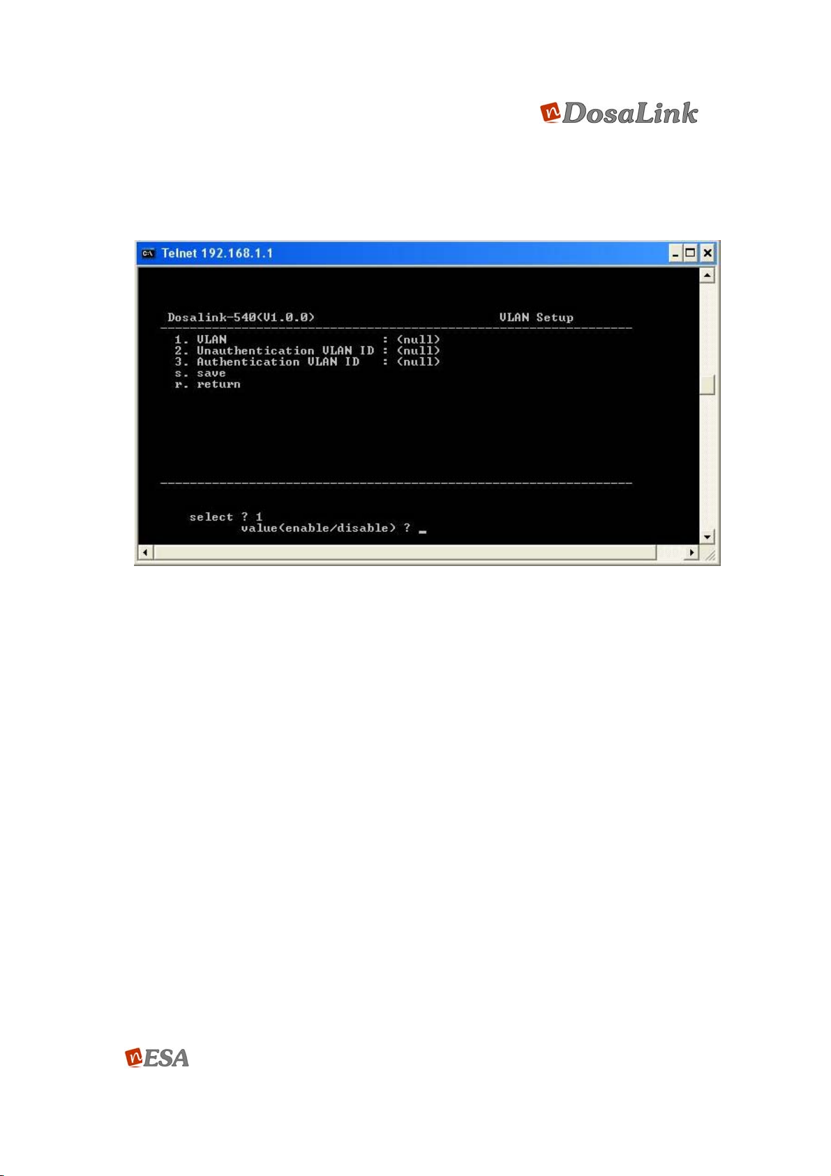
2. Unauthentication VLAN ID: Set the unauthentication client’s VLAN ID value (2 ~
4095).
3. Authentication VLAN ID: Set the authentication client’s VLAN ID value (2 ~ 4095).
Figure 68 VLAN Setup
13.9.8. WPA/ WPA2
1. WPA USE: Select either “enable” or “disable”.
2. WPA AUTH TYPE: Select to use either WPA-PSK or WPA-EAP when the
WPA is enabled.
3. WPA RADIUS IP: If the WPA-EAP is selected, then the Radius Server’s IP
address is input.
4. WPA RADIUS PORT: If the WPA-EAP is selected, then the Radius Server
Port is assigned.
5. WPA RADIUS SECRET: If the WPA-EAP is selected, then the Radius
Server’s Shared Secret is input.
6. WPA CIPHER SUITE: Select to use either “AES” or “TKIP”.
7. WPA KEY FORMAT: Select to use either “Passphrase” or “Hexa” in the “PreShared Key Format” if the WPA-PSK is selected.
8. WPA PRE-SHARED KEY: Input the keys as set in “WPA KEY FORMAT”.
Input 8 – 63 characters if the “Passphrase” is selected.
Input 64 chracters if the “Hexa” is selected.
User’s Manual 70/73
Ver. [E.1.1]

9. RSN/WPA2 USE: Select to use WPA2.
Figure 69 WPA/ WPA2 Setup
(a) RSN AUTH TYPE: This is the same as 2.
(b) RSN PREAUTH: Select to use of this function.
(c) RSN PREAUTH LIFE TIME: Establish the “Preauth Life Time”.
(d) RSN RADIUS IP: If the WPA-EAP is selected, then the Radius Server’s IP
address is input.
(e) RSN RADIUS PORT: If the WPA-EAP is selected, then the Radius Server’s
Port is input.
(f) RSN RADIUS SECRET: If the WPA-EAP is selected, then the Radius
Server’s Shared Secret is input.
(g) RSN CIPHER SUITE: Sele ct to use either “AES” or “TKIP”.
(h) RSN KEY FORMAT: Se lect to use either “Passphrase” or “H exa” in the “Pre-
Shared Key Format” if the WPA2-PSK is selected.
(i) RSN PRE-SHARED KEY: If the WPA2-PSK is selected, then input the Pre-
Shared Key.
(j) REKEY TIME: Establish the Rekey Time.
(k) REKEY PACKETS: Set the Rekey Packets.
(l) REAUTH TIME: Set the Reauth Time.
User’s Manual 71/73
Ver. [E.1.1]

Appendix I: Abbreviations and Acronyms
ADSL Asymmetric Digital Subscriber Line
AES Advanced Encryption Standard
AP Access Point
CTS Clear-to-send
DHCP Dynamic Host Configuration Protocol
DMZ Demilitarized Zone
DTIM Delivery Traffic Indication Message
EAP Extensible Authentication Protocol
IP Internet Protocol
ISP Intenet Service Provider
LAN Local Area Network
MAC Media Access Control
MD5 Message-Digest algorithm 5
MDIX Medium Dependent Interface Crossover
NAT Network Address Translation
TM
nESA
OS Operating System
PMP Point-to-MultiPoint
PPPoE Point-to-Point Protocol over Ethernet
PSK Pre-Shared Key
PtP Point-to-Point
RTS Request-to-send
SNMP Simple Network Management Protocol
SSID Service Set Identifier
SSL Secure Socket Layer
TCP Transmission Control Protocol
TKIP Temporal Key Integrity Protocol
TLS Transport Layer Security
TTLS Tunneled Transport Layer Security
nDosa Enhanced Security Algorithm
UDP User Datagram Protocol
VLAN Virtual Local Area Network
VPN Virtual Private Network
WAN Wide Area Network
User’s Manual 72/73
Ver. [E.1.1]

WDS Wireless Distribution System
WEP Wired Equivalent Privacy
WLAN Wireless Local Area Network
WPA Wi-Fi Protected Access
User’s Manual 73/73
Ver. [E.1.1]
 Loading...