

Page 1
POWER-FLOW PURGE CART
OPERATION MANUAL
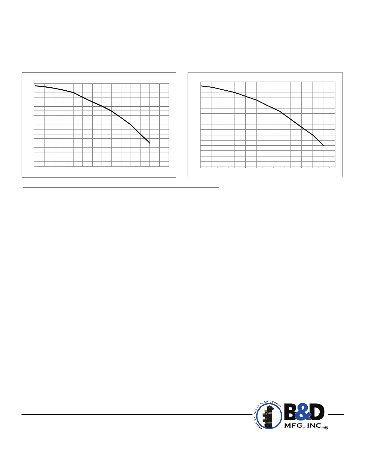
FT.HEAD
92
88
84
80
76
72
68
64
60
56
52
48
44
40
36
32
28
24
20
0 10 20 30 40 50 60 70 80 90 100 110 120 130 (US)
2Horse PowerMotor
gpm
FT.HEA D
84
80
76
72
68
64
60
56
52
48
44
40
36
32
28
24
20
0 102030405060708090100110(US)
1‐1/2Horse PowerMotor
gpm
NOTE: Read the entire instruction manual before starting the installation.
WARRANTY
The Power-Flow Purge Cart is warranted for one year from date of sale. Alleged defective product must be returned
to B&D Mfg., Inc., 901 9th Street, Scranton, Iowa 51462, for inspection via prepaid freight. Defective parts will be
repaired or replaced at the manufacturer’s discretion. No allowance for labor or property damage is implied.
Warranty of performance is limited to the table provided with the unit.
INTRODUCTION
These instructions cover the use of the B&D Power-Flow Purge Cart Part No. GT-304SS-1.5 and GT-304SS-2. The
Power-Flow Purge Cart is designed for flushing out air and debris in the loop field. It can also be used to introduce
glycol into the system. The package contains a water holding tank, cart with solid foam tires, hose with camlock
connections and a lift out filter screen for easy removal of debris.
SAFETY PRECAUTIONS
*Electrical Supply to flush cart must be a single 20 amp, 120 volt circuit. If using extension cord, do not exceed
manufacturer’s rating for cord.
*Servicing of closed loop systems should be performed only by trained and qualified service personnel. Proper
precautions should be taken to minimize risk of electrical shock when using a flush cart. Wear proper safety glasses
and work gloves.
*When transporting the cart, be sure to keep cart in an upright position and secured to avoid any damage to the
flush cart.
*Be sure to drain the tank after each use to prevent damage to the rubber seals of the pump. It is best to store the
flush cart in an area free of freezing temperatures.
*Must Read and Follow Anti-freeze Manufacturer’s Recommendations and Procedures for adding anti-
freeze solution to the system.
B&D Mfg, Inc
901 9th Street
Scranton, IA 51462
Phone (712) 652-3424
Fax (712) 652-3388
www.bdmfginc.com
1
Patent No. 5,244,037
Page 2
ASSEMBLY INSTRUCTIONS
Open the crate and install the 13” wheels. That’s it, because we have mounted our stainless steel tank, pump, motor
and hoses securely to a heavy duty cart for easy handling. Everything has been factory tested so that when it arrives,
it’s ready to go.
CAUTION: Must read all instructions in this manual before operating the Power-Flow Purge Cart.
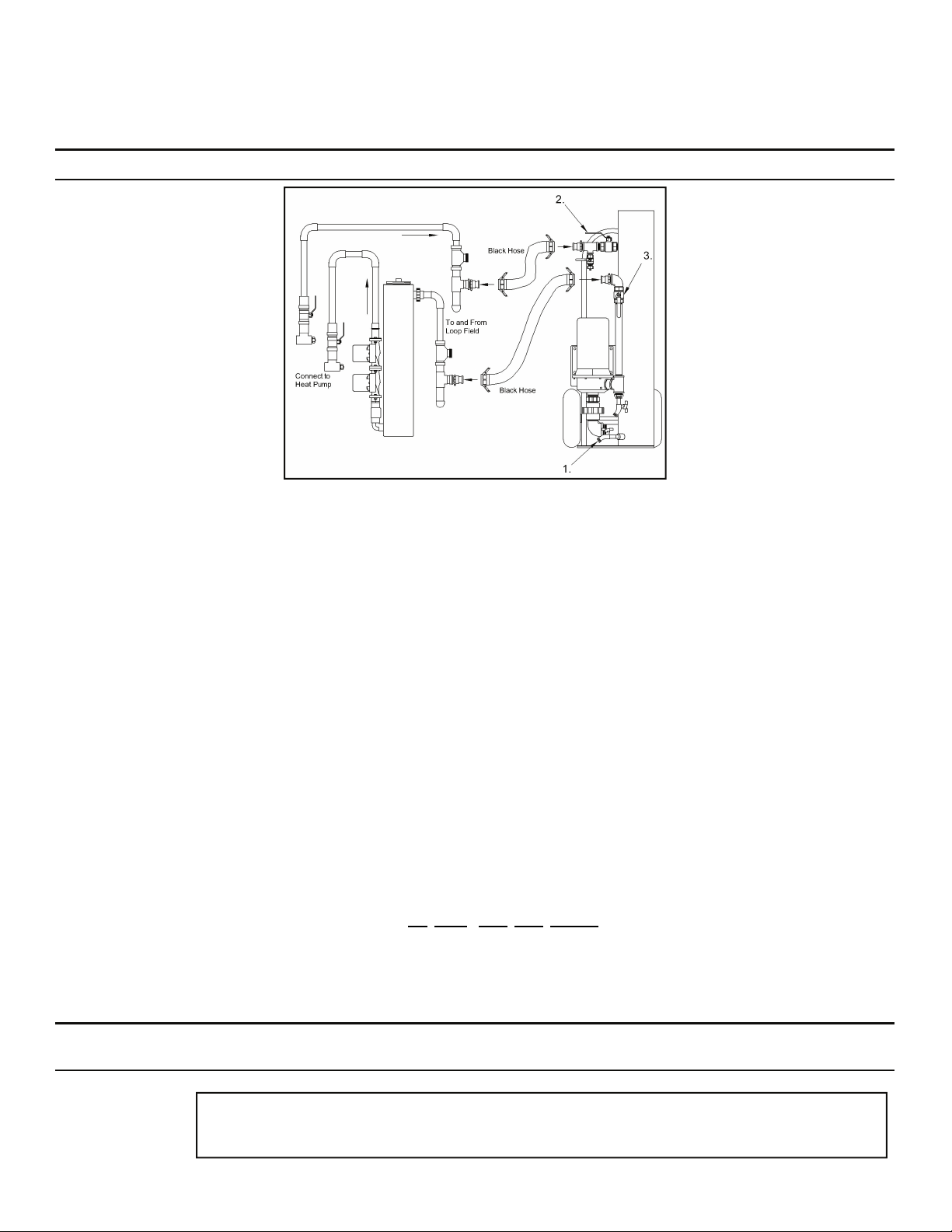
Fig. 1.
How to Flush a Loop Field
OPERATING INSTRUCTIONS
Connect the two provided camlock connections to the flush ports on the loop field piping system using sealant tape or
compound to prevent leaks.
NOTE:
Fig. 1
(
1.) There is a hose connection provided on the tank drainage connection to connect a water supply source. You
may control the amount of water supplied to the tank by regulating the valve on the drainage port.
Fig. 1
(2.), (3.) Make sure return valve (2.) is closed and discharge valve (3.) is opened. Allow water to fill tank while
If flushing a non-pressurized system be sure the flow center is properly isolated.
observing the water level at the discharge valve. When water level is at the level of the discharging valve (3.), close the
valve and allow the water to continue filling the tank to top of elbow. This will purge the air from the pump while filling
the tank, preventing an air lock.
Check screen position in tank to be sure it is below the return elbow, so all water goes through the screen to catch
debris.
NOTE
:
System should be filled with clean potable water.
Connect the provided hoses between the camlock connections on the purge cart with camlock connections now mounted
in the flush ports.
Make sure the power switch is in the off position before plugging in the power supply.
Plug in power supply for flush system using only a
20 amp, 120 volt circuit
. If using an extension cord, do not exceed
manufacturer’s rating for cord.
Open the valves on all of the fill and flush ports into the position that allows flow to and from the loop field.
Open the ball valves on the supply and return water lines of the purge cart system.
** IMPORTANT ** Keep water supplied to flush system tank to prevent pump from being run dry. Do not
** NOTE **
allow flush tank to overflow.
Turn on pump.
NOTE
:
If the pump is air locked, then turn the pump off. Disconnect the supply hose from the flush
port and place in the top of the tank and turn pump on. This will prime the pump and allow water to
circulate directly back to the tank. Re-attach the hose and begin the purging process over again.
2
Page 3

A
W
MODEL GT-304SS-1.5
Weight: 192 lb.
MODEL GT-304SS-2
Weight: 196 lb.
B
H
*Dimensions are approximate
1.5HP Motor 115V or 2 HP Motor 115V
A = Anti-Freeze Flush Drain B = 1 1/4" Full Port Valves
H = 53” W = 22 1/2”
OPERATING INSTRUCTIONS
When return water flow from the loop piping is established, stop the addition of supply water to the flush system tank
and
maintain a constant water level just above street elbow
loops until air ceases to escape from the flush system.
Check the system for proper flushing by closing the return water ball valve on the purge cart, carefully observing water
level in the tank. The water level should not drop more than 2-4 inches, if it does then all of the air has not been
removed from loop system. Continue opening and closing of the return valve while viewing the water level in the tank.
NOTE:
A proper flush of a system has been achieved when all valves in the system are opened and the water does not raise
more than 2-4 inches when the power switch is placed in the off position.
NOTE
expand. The raising and lowering of the water level is in proportion to the amount of system piping and the natural
expansion of polyethylene when exposed to pressure.
To add anti-freeze solution, close valve on return side of flush tank and open the anti-freeze flush valve (make sure
drain hose is attached to a separate container). If you know the amount of anti-freeze to add, you can discharge pure
water from the purge cart and measure the amount in gallons. You can then add anti-freeze solution from the top of the
purge cart. This will allow you to add a specific amount of anti-freeze to reach a desired concentration percentage. When
the required amount of anti-freeze is added, close the anti-freeze flush valve and open return side valve on flush tank.
NOTE
percentage. If using a non-pressurized flow center, please refer to “How to Flush an Earth Loop” to purge the
air from the interior piping (page 4).
Water level should be maintained to top of elbow when system is circulating and return valve is opened.
COMPLETED FLUSH OF SYSTEM CHECK
:
The reason the water level changes is because the pressure from the pump will cause the polyethylene to
:
Make sure the system is circulated for some period of time before measuring the concentration
by adding water as necessary. Continue flushing the
3
Page 4

flow
®
9. Any small
amounts of air
remaining in the
system will become
trapped and
/
®
flow center.
®
isolated in the GT
QT
10. Check the flow
with a flow meter
tool. Fill flow center
to bottom of dip
®
flow center.
®
tube elbow on a GT
flow center or to the
top of the elbow on
a QT
/QT
®
the GT
center pump(s).
7. Close valve (2.)
and disconnect
hose from tee (4.);
screw cap back on.
8. Open valve (1.)
and (2.); start
system.
4. Disconnect
hoses from tees
(3.) and (4.) Put
cap back on tee
(3.).
5. Connect 1”
clear hose with
swivel connector
to tee (4.), put
hose into top of
flow center.
6. Open valve
(2.) and turn on
flow center; flush
inside piping and
heat pump with
How to Flush an Earth Loop with a Buried Manifold
1. Close valves (1.)
and (2.), located
on lines to and
from the loop
field.
2. Remove screw
caps from tees (3.)
and (4.), then
connect flush cart
hoses to 1“ MNT.
3. Flush and purge
loop field
thoroughly with
flush cart.
4
©eg 1995-2013 B&D Mfg., Inc. all rights reserved.
Patent No. 5,244,037
08-2013
 Loading...