

Page 1
LET US MAKE YOUR GROUND SOURCE HYDRONICS
SYSTEM EASIER AND MORE EFFICIENT
www.bdmfginc.com
HYDRONIC BUFFER TANK
1
Page 2
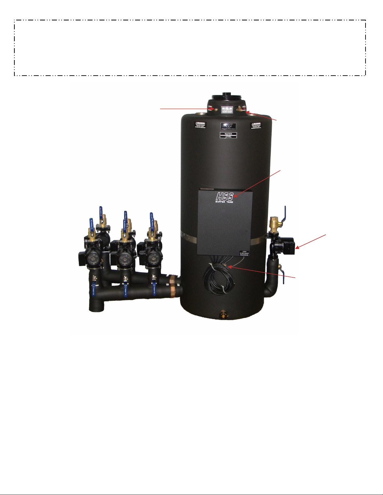
IT’S FINALLY HERE A HYDRONIC BUFFER TANK WITH THE PUMPS, CONTROLS AND VALVES
ALL IN ONE. NO MORE HASSLES OF TRYING TO MOUNT EVERYTHING. ALL YOU HAVE TO DO
IS PLUMB THE LINES, WIRE THE THERMOSTATS, AND HEAT PUMP, THEN FILL THE SYSTEM.
THE NON PRESSURIZED TANK KEEPS AIR OUT OF YOUR SYSTEMS SO YOU DON’T HAVE TO.
Pressure Relief Valve
Manual Relief Valve
Control Box w/ transformer
and Printed Circuit Board
115V Hydronic Side w/ 3/4” or 1” Ball Valve
230V Pump Ground Source HP
Thermostat Wire Entrance
AVAILABLE SIZES:
HSS®-12, HSS®-20, HSS®-30, HSS®-40, HSS®-60, HSS®-80
2” inlet & 3/4”or 1” Ball Valve outlets
Water temperature not to exceed 150 degree max. Designed for 6 to 10 gallons
per ton of buffer volume. (Tank is not designed to be a hot/chilled water storage
device) 115V Pump on Hydronic Heat Side & 230V Pump W/ Water Side.
Hydronic Pump Relay standard Sensor for One Stage Heat, Two Stage Heat or
Heating & Cooling built in.
***CUSTOM TANKS MADE TO ORDER***
***CUSTOM TANKS MADE TO ORDER***
***CUSTOM TANKS MADE TO ORDER******CUSTOM TANKS MADE TO ORDER***
2
Page 3
Installation Guidelines and Procedures for B & D MFG
.,
INC.
SAFETY INSTRUCTIONS
This safety alert symbol will be used in this manual to draw attention to safety related instructions.
When used, the safety alert symbol means: ATTENTION! BECOME ALERT! YOUR SAFETY
IS INVOLVED! FAILURE TO FOLLOW THESE INSTRUCTIONS MAY RESULT IN A
SAFETY HAZARD.
HSS® Series Hydronic Buffer Tank
TANK PLACEMENT REQUIREMENTS
A level location with 36" of clearance on the front of tank required. This
allows enough room to hook-up the manifolds for the Hydronic Zone and
Water-to-Water Heat Pump. An allowance for 36" of clearance on the top of
the tank (between lid and ceiling) for insertion of an optional flow meter tool,
which is recommended. Buffer Tank location shall be in a conditioned air
space to prevent condensation.
WARNING: Electrical Shock and potential circuit damage. Disconnect power supply before beginning installation.
Failure to follow these instructions could result in serious personal injury or death and property damage.
Improper wiring and wire can cause electrical shock and fires. Wiring connections must be made in
accordance with all applicable electrical codes and ordinances. Use copper wire only. Failure to follow these
instructions could result in serious personal injury or death and property damage.
Potential electrical overload. Each circuit is limited to a maximum of 3 amps and 1/3 HP. The
combined load for the controller is limited to 15 amps and 1 HP maximum. Failure to follow these instructions
could result in serious personal injury or death and property damage.
ELECTRICAL SERVICE & CONNECTIONS
The HSS® Buffer Tank requires a dedicated 20 amp, 120 volt circuit. The
primary wiring must be in accordance with Local Codes and that of the
National Electric Code. Low voltage wiring must be isolated from primary
voltage lines and connections.
The individual circulator pumps for the Hydronic Zones are pre-wired and
labeled at the control panel for field connections, these pumps are factory
assembled for 120 volts. The Water to Water (load side) circulator pumps shall
be wired to the heat pump’s control box; (see heat pump manufacturers wiring
diagram for proper wiring connections) and are typically wired with the
compressor contactor load side. Follow the color-coded schematic of low
voltage wiring. (see page 7)
WARNING: Load side circulator pumps are 220 volts. It is important to tag the Buffer Tank as having
separate power sources for servicing.
WARNING: HSS® Buffer Tank is a non-pressurized unit and should never be pressurized.
3
Page 4

THERMOSTAT WIRING
The HSS® can provide heating/cooling control and heating only control
depending on the system requirements. Any terminal block located on the
HSS® control board can be used for heating and/or cooling however the
HO/HC jumper must be on HC to enable cooling control for its corresponding
zone. (See schematic on page 7)
Heating & Heating Cooling- Connect thermostat wire R to its corresponding
pump zone on the HSS® Control R terminal. Connect thermostat wire Y to its
corresponding pump zone on the HSS® Control Y terminal. If the zone
thermostat requires 24V power connect thermostat wire C to its corresponding
pump zone on the HSS® Control C terminal.
Master Heating/Cooling- The Heat/Cool master thermostat determines the
system Heat/Cool setting. Connect thermostat wire R to its corresponding
pump zone on the HSS® Control R terminal. Connect thermostat wire Y to its
corresponding pump zone on the HSS® Control Y terminal. Connect
thermostat wire O to its corresponding pump zone on the HSS® Control O
terminal. If the zone thermostat requires 24V power connect thermostat wire
C to its corresponding pump zone on the HSS® Control C terminal.
PIPING HOOKUP
The HSS® Buffer Tank has Stainless Steel unions and pipe connections. It is
recommended when using transition fittings between steel and PVC, CPVC or
PE style plastic pipe. Extreme caution must be used when inserting steel into
plastic fittings or plastic into steel fittings. The HSS® Buffer Tank does
experience a wide range of temperature and over tightening of plastics fittings
can lead to fitting failures, water loss with in the HSS® Buffer Tank and
extreme cases, pump failure due to lack of water. It is recommended on plastic
style threaded joints the joint be snugged only and a good grade of thread
sealant be used. The system, once filled and purged, has capabilities of having
air handlers approximately 30' higher than the lid of the Buffer Tank and the
(see schematic page 7)
lid may be removed without water spilling out of the tank. All threaded fittings
on the HSS® Buffer Tank should be backed up with and additional wrench to
ensure damage does not occur to the Buffer Tank from twisting of fittings. All
lines should be insulated to prevent condensation forming on lines.
4
Page 5

PURGING HSS® BUFFER TANK
The HSS® Buffer Tank can have several loops or circuits and each one
should be purged separately. The HSS Buffer Tank shall be filled with water
prior to running any of the circulator pumps. Keep a water source nearby to
fill the tank as necessary. As air is relieved from the system piping water will
need to be added. Prior to running any of the pumps except the 15-58
pumps, the large metal screw on the back of the Grundfos pump shall be
removed, and the pump shaft turned by hand to allow air to be purged from
the pump. ( Check 3– speed pump for right setting.)
Turn on the 1st zone pump, by jumper or thermostat, and monitor the water
level in the HSS® Buffer Tank, as the water level drops in the Buffer Tank,
add water to maintain a minimum level of water in the tank. A minimum
level would be just below the return line pipe discharge point. The reason for
a low water level while filling is to allow air to vent without splashing water
out of the Buffer Tank. When the water level rises, 1-2" above the discharge
point in the Buffer Tank then shut off the 1st zone circuit and start the 2nd
zone circuit process. Repeat this process until all zones have been purged.
It is important to note the arrow on the pump should be pointing up this will
ensure proper flow direction. The isolation pump flanges should be turned
on. This is accomplished when the line on the valve is parallel with the pipe
direction. There may be occasions when a pump for an air handler is located
two stories above the HSS® Buffer Tank and will not have enough head to
purge the air out of the line. In those cases turn the isolation valve shut and
pull out the smaller pump and bolt in a larger pump and open the isolation
flanges. Once the air handler has been purged, then shut off the isolation
valves on the flanges. Unbolt the temporary pump and bolt in the permanent
pump, open the isolation flanges while pump is running open bottom flange
first. Once the pump runs and pushes a small amount of air out of the system
the pump will maintain the prime. If you should loose prime on this circuit
you would need to re purge as described above. When all the hydronic zones
are purged then move to the water-to-water heat pump manifold and start the
purging process as started with the zone pumps. Be sure to purge the air out
of the pumps first.
WARNING: HSS® Buffer Tank is a non-pressurized unit and should never be pressurized.
5
Page 6

PROGRAMMING OF THE B&D TEMPERATURE CONTROLLER
1. Power needs to be applied to the HSS Buffer Tank, the Temperature controller display will turn on.
2. Press and hold the MODE button for 5 seconds and it will enter programming mode. After 2 seconds the
temperature scale will show on the LCD display. By pressing the up or down button allows you to change
from “FAR” or “CEN”.
3. Press mode button once and enter the control type. The display will show “TY1”. After 2 seconds the
LCD will show “HEA” or “COL”, by pressing the up and down button allows the setting change from
“HEA” or “COL”. The setting must be “COL”.
4. Press the mode button again to change to temperature differential “SP1”. After 2 seconds the LCD will
display a number, by pressing up and down button allows the setting change the number setting.
5. Press the mode again and the LCD displays “HS1”, after 2 seconds the LCD will show current setting.
The hysteresis time, would be a built in time delay. By pressing the the up and down button to set the
desired time. Change to zero to disable.
6. Press mode button once and enter the control type. The display will show “TY2”. After 2 seconds the
LCD will show “HEA” or “COL”, by pressing the up and down button allows the setting change from
“HEA” or “COL”. The setting must be “HEA”.
7. Press the mode button again to change to temperature differential “SP2”. After 2 seconds the LCD will
display a number, by pressing up and down button allows the setting change the number setting.
8. Press the mode again and the LCD displays “HS2”, after 2 seconds the LCD will show current setting.
The hysteresis time, would be a built in time delay. By pressing the the up and down button to set the
desired time. Change to zero to disable.
The controller includes a locking function that will prevent accidental reprogramming. The soft lock is enabled
and disabled by pressing both the UP and DOWN buttons for five seconds. The LCD will show “LOC” to
indicate the controller is locked. The LCD will show “UNL” to indicate that the controller is now unlocked. The
soft lock will retain its setting through power interruptions.
Step Annunciator Description Display
1 F – C Fahrenheit or Celsius Scale F
2 ty1 Heating or Cooling Col or HEA
3 Sp1 Set Point Temperature #
4 ds1 Differential Temperature #
5 HS1 Timer for Delay #
6 Repeat steps 2-5 for stage 2
*Note the B & D Temperature control will automatically end programming if no keys are depressed for a
period of fifteen seconds. Any settings that have been input to the control will be accepted at that point.
6
Page 7

7
Page 8

DIAGNOSTICS
Water runs out of the top of the HSS® Buffer Tank
1. Air in zones will cause water to over flow when pumps are shut off.
2. A water line leak above the height of the Buffer Tank could cause air
to enter and allow the water to run out.
3. If the HSS
®®®®
Buffer Tank was filled during the air conditioning season
and then operating in the heating season, the water level can rise and
overflow.
4. A properly purged system will result in less than 2"of water level
movement between pumps running and pumps not running. If
movement is greater than 2" air is still present in the system.
Water level continues to drop in the Buffer Tank
1. If it is a new install as air continues to purge the water level will
drop. This process should not last much over a few days of operation.
2. During the heating season and going into the cooling season the
water level may drop but should remain near that level.
3. Possible leak in the hydronic loop or in the heat pump loop.
Water will not circulate on the hydronic zone side
1. Check that all isolation valves are turned on.
2. Check that all pumps are set with the arrow up.
3. Power is at the HSS
®®®®
Flow Control.
4. Air has been purged out of all air handlers.
5. Pumps have a sufficient pump curve to meet the needs of the zone.
6. A zone thermostat may not be calling for heat.
The lid will not come off of the Buffer Tank
1. The lid was installed to tight originally.
2. The purge valve was not opened to the atmosphere.
The Heat Pump will not run but the zone pumps are operating
1. The Digital Aqua Stat not programmed correctly.
2. The water temperature is at a point that all temperatures are satisfied.
Note: When filling a HSS
®®®®
Buffer Tank with 40°F – 60ºF water
the cooling set point may need to be lowered to start the heating
cycle. Once water temperature is above 70ºF the cooling set point
should be reset to original setting.
be pressurized.
Warning: HSS® Buffer Tank is a non-pressurized unit and should never
8
Page 9

®
Non-Pressurized STAINLESS STEEL Hydronic Buffer Tank
GT Stainless Steel Tank
Tank Size
Total Hydronic Circuits
Total W/W Circuits
B-B&G; G-Grundfos
Voltage (1-115; 3-230)
*Hydronic circuit ball valve 3/4”on 15/58, 1” on 26/99-3 speed pump.
W /W Side 1-1/4” Ball Valve
Tank Water Level is 3” to 4” Down on Main Tank
Control Board Electrical Data:
115V/Single Phase 15 amp Circuit
HSS60-3-1-G-13
1 1/4” FPT
w/ Ball Valve
HSS
®
GT BUFFER TANK Flow Center Physical Dimensions (in.)*
Max Gal
Storage
12 21” 7 1/2” 7” 9” 24” 49” 57 1/2” 10” 17” 1 1/4” MPT 1 1/4” U 30#
20 21” 7 1/2” 7” 9” 24” 49” 57 1/2” 13” 20” 1 1/4” MPT 1 1/4” U 38#
30 21” 7 1/2” 7” 9” 24” 49”
40 21” 7 1/2” 7” 9” 24” 49”
60 21” 7 1/2” 7” 9” 24” 49”
80 21” 7 1/2” 7” 9” 24” 49” 54” 25” 31” 2” FPT 2” U 97#
Max
Hydronic
Circuits
3
6
9
12
12
12
9
G
H I J K L M N O P
54” 16” 23” 1 1/2” FPT 1 1/4” or 2” U 52#
54” 18” 25” 2” FPT 1 1/4” or 2”U 60#
54” 22” 29” 2” FPT 2” U 84#
* Dimensions are approximate
Q
Wt
Tank
Page 10
HSS® BUFFER TANK WARRANTY
15-58
B & D Mfg., Inc. warrants for a period of three (3) years from date of purchase that all HSS® Buffer Tank pumps and circuit boards are
free from defects in materials and workmanship. B & D Mfg., Inc. warrants for a period of five (5) years from date of purchase that all
HSS® Buffer Tank, stainless steel tanks only, are free from defects in materials and workmanship. B & D Mfg., Inc. warrants for a
period of one (1) year from date of purchase that all other parts are free from defects in materials and workmanship. Defective parts will
be repaired or replaced at the Manufacturer’s discretion. No allowance for labor or property damage is implied.
ALL WARRANTY PRODUCTS MUST BE RETURNED WITHIN 30 DAYS OF
RECEIPT OF REPLACEMENT TO RECEIVE CREDIT.
Seller's liability for any breach of this Warranty shall be limited solely to replacement or repair, and the sole option of seller, of any part
or parts found to be defective during the Warranty period provided the Product is properly installed and is being used as originally
intended. Buyer must notify Seller of any breach of this Warranty within the aforementioned Warranty period: defective parts must be
shipped by Buyer to Seller with transportation charges prepaid.
It is expressly agreed that this shall be the sole and exclusive remedy of the buyer. Under no circumstances shall seller be liable for any
costs, loss expenses damages, special damages, incidental damages of manufacture, sale, use or repair of the product whether based
upon warranty, contract, negligence or strict liability. In no event will liability exceed the purchase price of the product.
The warranty and limits of liability contained herein are in lieu of all other warranties and liabilities, expressed or implied. All implied
warranties of merchantability and fitness for a particular purpose are hereby disclaimed by seller and excluded from this warranty.
Seller neither assumes nor authorizes any person to assume for it, any other Warranty obligation in connection with the sale of the
Product. This Warranty shall not apply to any Product or parts of Products which (a) have been repaired or altered outside of seller’s
facilities: or (b) have been subject to misuse, negligence or accidents: or (c) have been used in a manner contrary to seller’s instructions.
FORM lws
REV 2006/Replaces All previous Warra nty Statements
Warning: HSS
®
Buffer Tank should never be used with an outdoor
wood boiler. Outdoor wood boilers can produce water temperatures
above 150 degrees and will void ALL WARRANTIES.
901 9th Street Scranton, IA 51462
B & D Mfg., Inc.
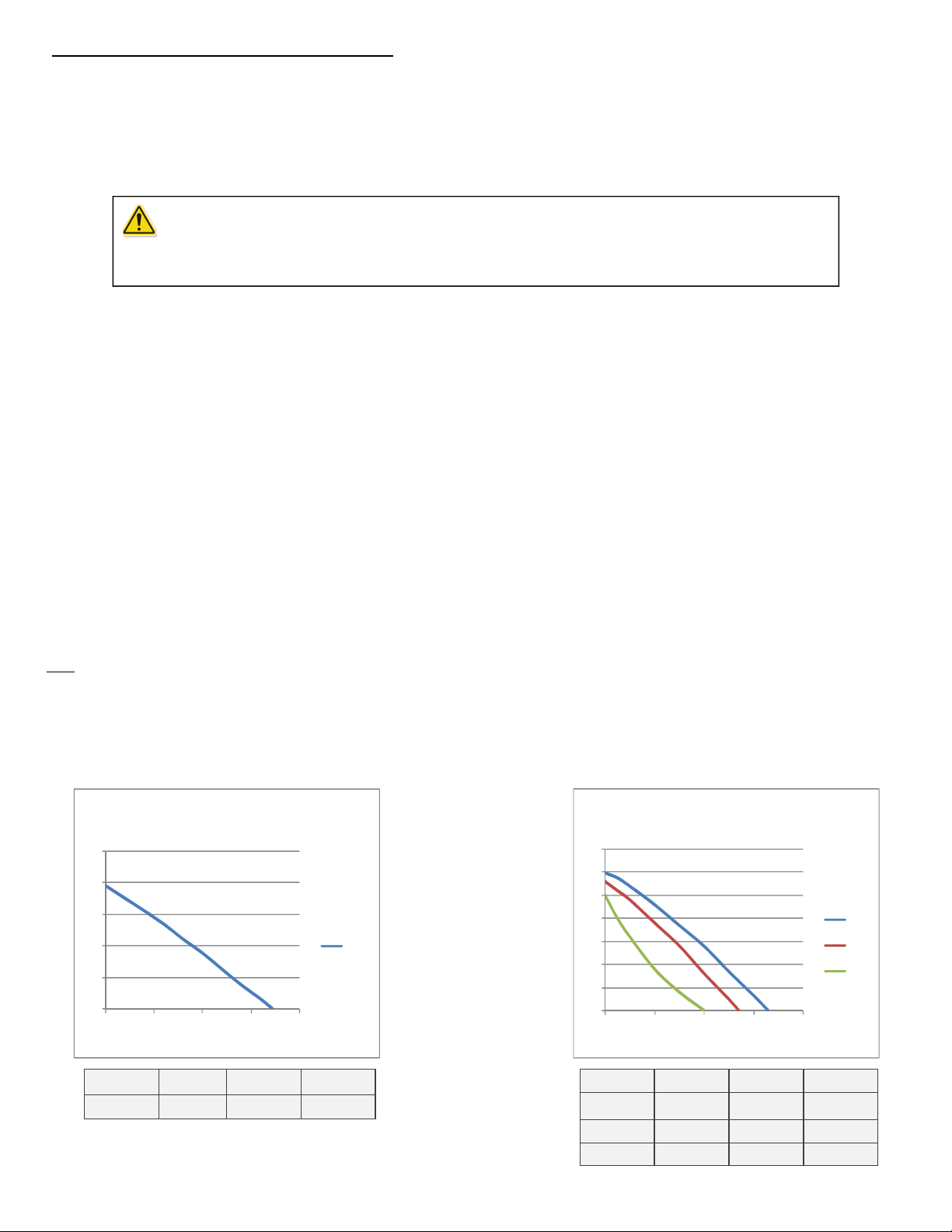
Hydronic 115V pump curves.
15-58
25
20
15
10
5
0
0 5 10 15 20
Volts Speed Amps Was
115 1 .75 89
35
30
25
20
15
10
5
0
0 10 20 30 40
Volts Speed Amps Was
115 1 1.8 197
115 2 1.5 179
115 3 1.3 150
© e.g. 2009-2012 B & D Mfg., Inc. all rights reserved
26-99
HI
MED
Low
 Loading...