

Page 1
EA® FLOW CENTER
INSTALLATION INSTRUCTIONS
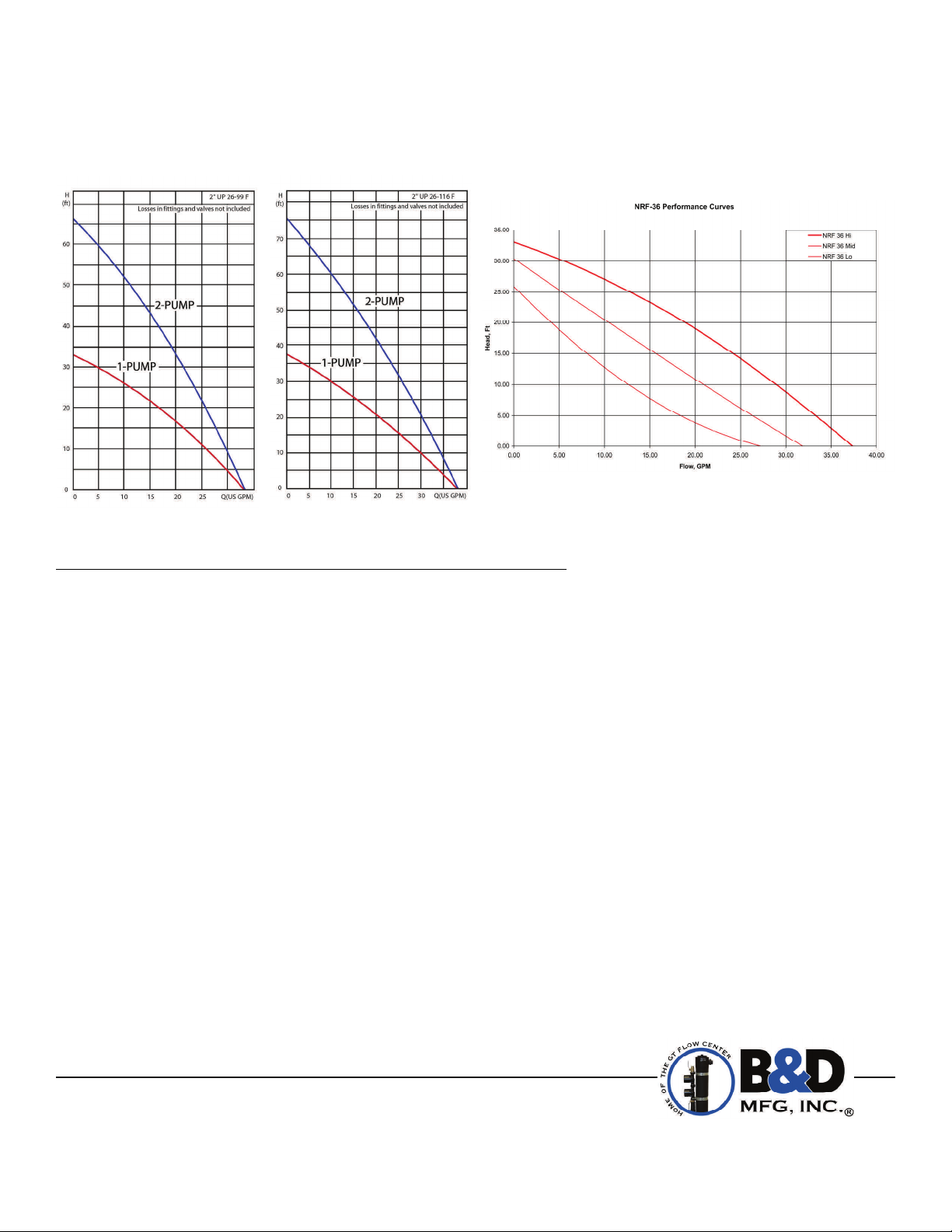
Fig. 1.
26-99 Pump Center Flow Chart
NOTE: Read the entire instruction manual before starting the installation.
This flow center is warranted for two years from date of sale, excluding the 3-230KFC-SS, which is only a two year
warranty. Alleged defective product must be returned to B&D Mfg., Inc., 901 9th Street, Scranton, Iowa 51462, for
inspection via prepaid freight. Defective parts will be repaired or replaced at the manufacturer’s discretion. No allowance
for labor or property damage is implied. Warranty of performance is limited to the table provided with the unit and only
when being used in a closed-loop, heat pump system. No warranty of performance is provided when pump(s) are
provided by others.
These instructions cover the installation of the EA
SS230KFC and, 0-0E-A-SS230KFC. The EA
ground source heat pumps. The package contains a water vessel, an air-eliminating dip tube, a pump protecting check
valve, pump(s) and ball valves that allow the pump(s) to be removed for service without loss of fluid to the system
Installing and servicing of air conditioning and heating equipment can be hazardous due to system pressures and
electrical components. Only trained, qualified personnel should install, start-up and service this equipment.
Untrained personnel can perform basic maintenance functions such as cleaning coils or cleaning and replacing filters. All
other operations should be performed by trained service personnel.
When working on the equipment, observe precautions in the literature, tags, stickers and labels attached to the
equipment and to any other safety precautions that apply.
Follow all safety codes. Wear safety glasses and work gloves.
Fig. 2.
26-116 Pump Center Flow Chart
WARRANTY
INTRODUCTION
Flow Center Part No. 2-2E-A-SS230KFC, 2-1E-A-SS230KFC, 1-1E-A-
®
Flow Center is a prepackaged pumping station to be used with closed-loop,
®
SAFETY CONSIDERATIONS
Fig. 3.
NRF36 Pump Center Flow Chart
B&D Mfg, Inc
901 9th Street
Scranton, IA 51462
Phone (712) 652-3424
Fax (712) 652-3388
www.bdmfginc.com
1
Patent No. 5,244,037
Page 2
INSTALLATION
The EA
has two separate pumping circuits designed to work with two heat pumps or a large dual stage heat pump with
®
two circuits. Each pumping circuit shall be checked with the performance curves (See Fig. 1 ,2 & 3). To ensure adequate
flow, the selection must be based on your specific system design. Total system flow shall be no greater than 28 GPM.
The flow center must be located between the heat pump and the ground source system heat exchanger. Location should
be selected on the basis of ease of installation and future service. The flow center is used for filling, flushing, air
elimination, adding anti-freeze and operating the system. This flow center should never be pressurized.
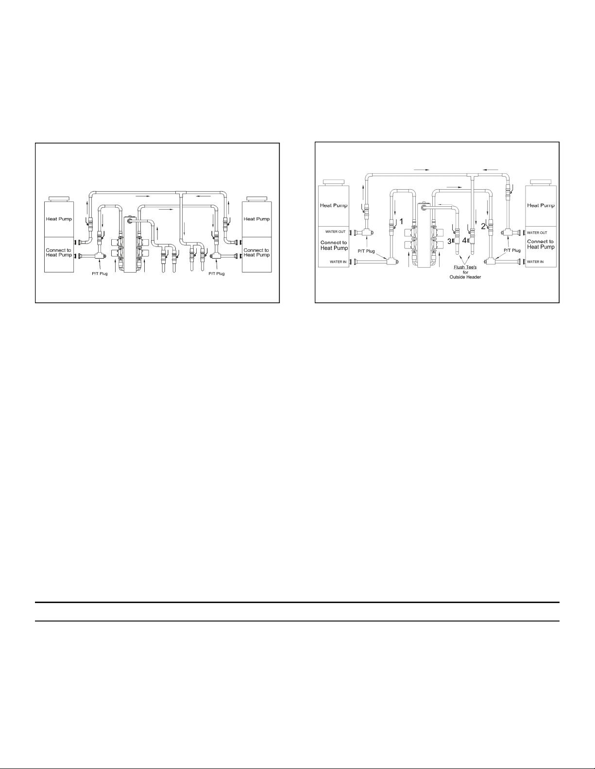
Fig. 4. Recommended Piping Schematic For
Maximum Flexibility (Required With
Internal Headers)
Fig. 5. Recommended Schematic (For Use with
Underground Headers; Flush Cart
Required)
The recommended piping schematic is usable with all types of closed-loop, ground source heat pump systems, vertical
bore holes, horizontal loops, slinky, outside headers or inside headers. This recommended method allows for isolating
the heat pump or the loop field for separate flushing and purging. Additionally, the flow through the loops can be
reversed, which may be required when using external headers.
NOTE: The EA
Flow Centers are designed to work with one common loop field. More than one flow
®
center on a common loop field will not work properly. Call B&D Mfg., Inc. for information on equipment
designed for multiple heat pumps.
Fig. 4 Illustrates a recommended piping schematic that can be utilized when an internal header is used and separate
purging of the heat pump and the ground loop is not required.
It is recommended that a tee with a threaded plug is located between the heat pump and the ground loop. This
plug allows the air to be vented from the system piping and will help remove air from the system during start up.
NOTE: Loops should not contain any dirt or debris prior to connecting to the flow center.
Fig. 5 Illustrates a recommended piping schematic for a system with underground headers.
Piping is similar for either schematic with the exception of Fig. 3 showing all earth loops penetrating the mechanical area
of the interior wall. Provide ball valves and P/T ports where indicated. Ball valves shall be the same as pipe size or
greater. The flow center should be fastened to the wall with the bracket provided and all piping should be adequately
supported. All piping shall be properly sized for the flow rate (GPM) required by the system. Reduce pipe size only at
flow center and heat pump as necessary to make connections.
PROCEDURE 1—FILL AND FLUSH A NEW SYSTEM
On systems where the ground loop has been filled and flushed by the loop installer, skip to Procedure 3.
Ensure that all piping is installed according to one of the piping schematics.
NOTE: Incorrect piping may not eliminate the air pockets.
1. Open the top of the canister and fill with clean potable water.
2
Page 3

2. Open the ball valves on both sides of the pumps.
3. Remove the screw on the end of the Grundfos pump motor and rotate the motor shaft with a small screwdriver.
This vents air out of the pumping chamber and lubricates the motor bearings. When water appears at the screw
opening, replace the screw.
4. Close all loop header valves except one pair (See Fig. 3).
NOTE: Before proceeding, be sure there is sufficient water available to fill the system without stopping
the pumps or allowing the canister to run out of water.
5. Start the pumps and add water through the open top of the canister until a full stream of water is returning back
to the canister, or use a flow meter tool to determine the flow rate back into the canister.
CAUTION: To prevent damage to the pumps, only add clean potable water to the flow center.
6. Isolate all but one loop; when the first loop is full, close the loop valves. Open the next pair of valves to fill/flush
the second loop. Follow the same procedure to fill/flush all loops.
7. When the last loop is full and flushed, open all loop valves to the flow center. Water will now circulate through the
entire ground source system and the flow center.
PROCEDURE 2—FLUSH AN EARTH LOOP WITH A BURIED MANIFOLD (OPTIONAL)
1. Follow instruction sheet provided with flow center (How to Flush a Earth Loop with a Buried Manifold).
PROCEDURE 3—ADD ANTI-FREEZE
Anti-freeze may be added at any time.
1. Calculate the correct amount of anti-freeze for the system and dilute if necessary for good circulation.
2. Attach flow meter tool to the return tube on the flow center and place the discharge of the flow meter tool into
separate container. Operate the flow center while using the isolation valve above the pump to control the amount
of water discharged into the container. At this point, you can begin adding the anti-freeze through the top of the
flow center. This will allow you to estimate how much anti-freeze is being added to the system.
3. When the correct amount of anti-freeze is added, shut pump off. Place flow meter tool return tube back into the
canister and reactivate the pumps, continually running them to circulate and mix the anti-freeze.
4. Finish filling flow center to the bottom of the elbow on the loop side with water and/or anti-freeze and close the
canister cap hand tight only. DO NOT over tighten cap as it will be difficult to remove for future service and cause
damage to the flow center. A coating of petroleum jelly on the threads will help in removing the cap for the next
inspection. Use a flow center wrench (Part 1-FCW) when removing lid to prevent damage.
PROCEDURE 4—START-UP
1. By using the flow meter tool, monitor the flow (GPM) being pumped through the entire system. If the flow is not
correct, check that the proper flow center has been selected for the application using curves from Fig. 1 and 2. If
the pump curve indicates the proper flow center was installed and the GPM is less than the system requires, an
obstruction in the system is restricting flow.
NOTE: Remaining air will normally be eliminated over a 24-hour period.
2. Air elimination on inside headers is simply done by re-purging each loop through the flow center and adding
water as needed. On outside headers, it is best to let the flow center run. Open valve No. 2 to bypass the heat
pump. This will provide additional pipe velocity on the ground loop and help remove air. During normal operation
air will continue to be eliminated through the flow center.
NOTE: If the water level inside the canister changes after the pumps are turned off air is present in
the system. Continue to purge the system until all air is removed.
3
Page 4

MODEL 1-1E-A-SS230KFC
Weight: 54 lb.
A A A
MODEL 2-1E-A-SS230KFC
Weight: 65 lb.
MODEL 2-2E-A-SS230KFC
Weight: 74 lb.
B
H
B
B
D
Electrical: 1/60/230V
Insulation: 3/8” Approx. Volume of Fluid: 5 gal.
A = 1 1/4" IPT B = 1 1/4" FPT H = 42 1/2" D = 21"
LETTER AFTER MODEL NUMBER FOR PUMP NEEDED: G=2699-3 Speed(230V) M=26-116 B=NRF36
CAUTION: For proper operation, water must be added as air is eliminated. The amount of water will be in proportion to
the amount of air eliminated.
3. After all air has been eliminated and full flow established, close valve No. 2 to place the system back into
full operation.
SYSTEM READY
The complete system is now operational and ready for testing. Use the flow meter tool (Part 1-WFT40) which slips over
the inlet pipe inside the flow center. Read the actual flow rate being pumped through the flow center. By closing all the
loop valves but one pair, an actual flow rate can be read on the meter for each ground loop. This will indicate that all
loops are flowing properly. If any loop shows a significant reduction of flow an obstruction may be present in the loop.
Remove flow meter from the flow center canister and allow the pumps to run continuously for 24 hours. The flow center
will continue to eliminate any small air bubbles that remain in the system.
08-2013
B&D Mfg, Inc
901 9th Street
Scranton, IA 51462
Phone (712) 652-3424
Fax (712) 652-3388
www.bdmfginc.com
4
©eg 2009-2013 B&D Mfg., Inc. all rights reserved.
Patent No. 5,244,037
 Loading...