

Page 1
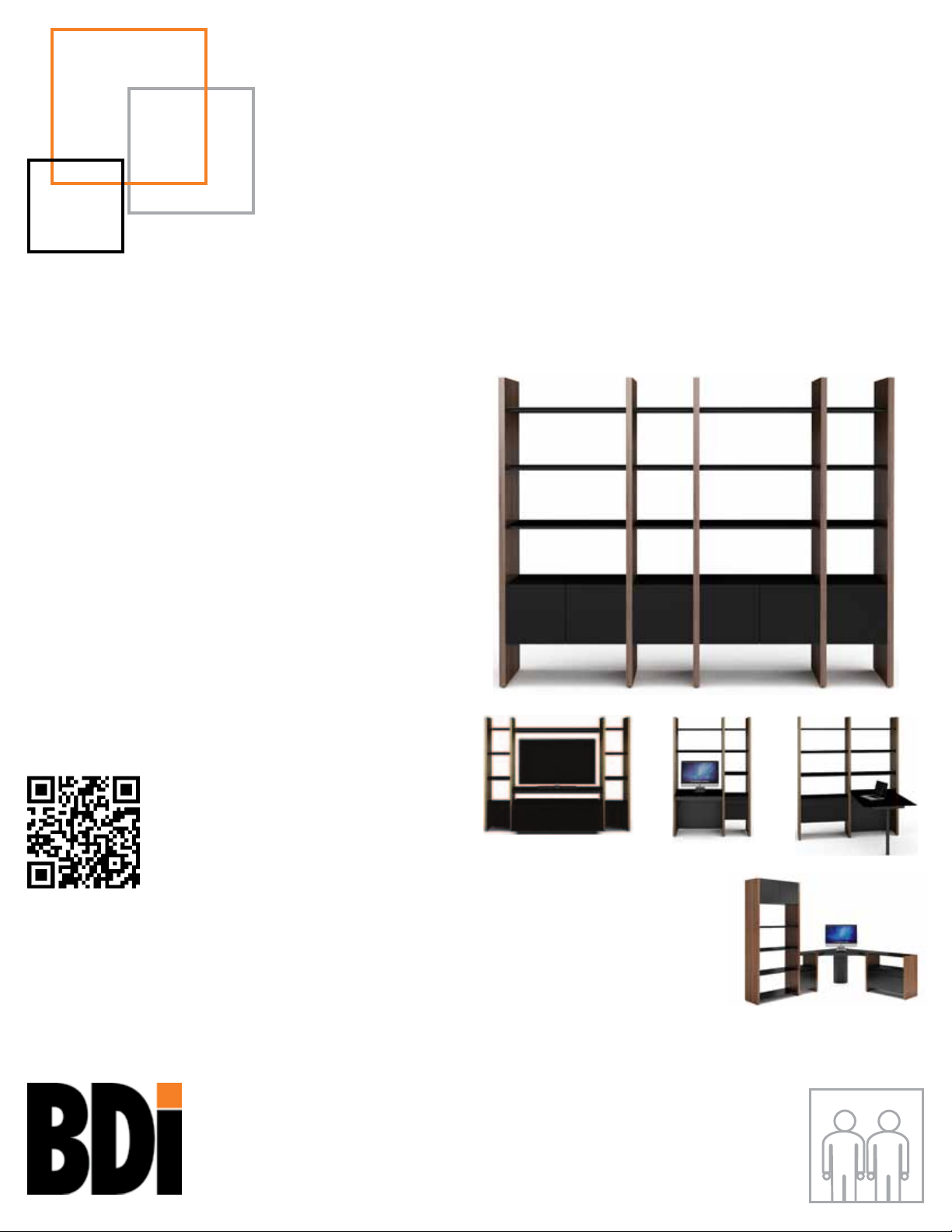
SEMBLANCE
modular system
MAIN
ASSEMBLY
INSTRUCTIONS
To view the Semblance assembly video,
scan this code with a QR reader or visit
http://www.bdiusa.com/semblance/
assembly.shtml
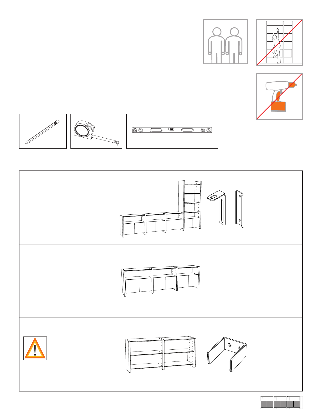
TWO PERSON ASSEMBLYB DIUSA. C O M
Page 2
Semblance System
Your SEMBLANCE System Furniture is
engineered for easy assembly.
Carefully follow this procedure to prevent
any damage.
Placement and
Maintenance
SEMBLANCE System Furniture is
designed for indoor use on level floors.
Clean glass with glass cleaner, steel parts
and wood veneer with a moist cloth.
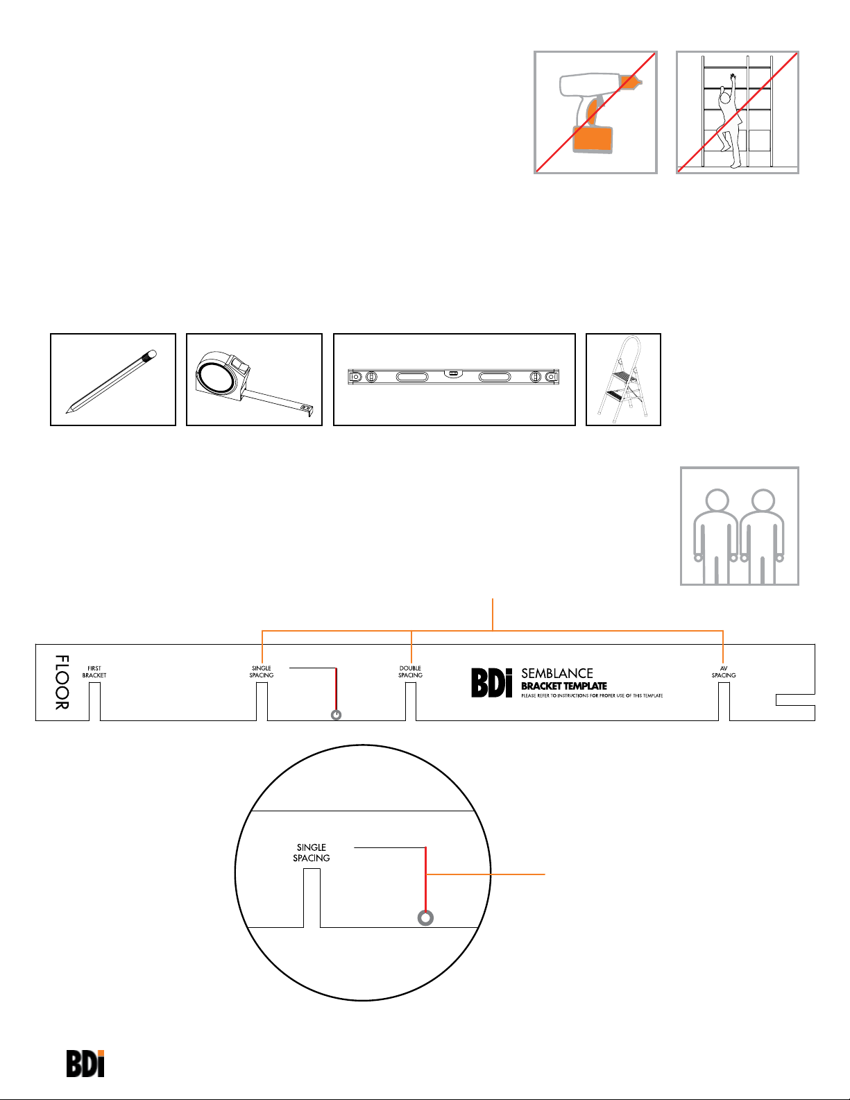
You will need:
Semblance Wall
Bracket Template
32"
This Template helps locate the various
positions of the second Wall Bracket.
2
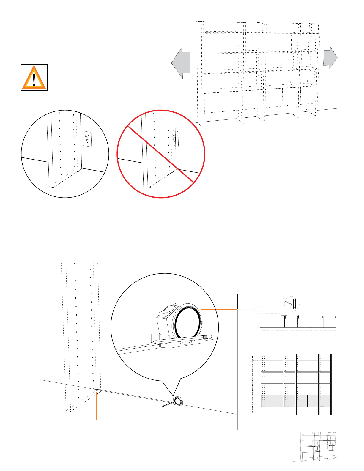
This is a leveling string to level the
placement of your Wall Brackets.
Page 3
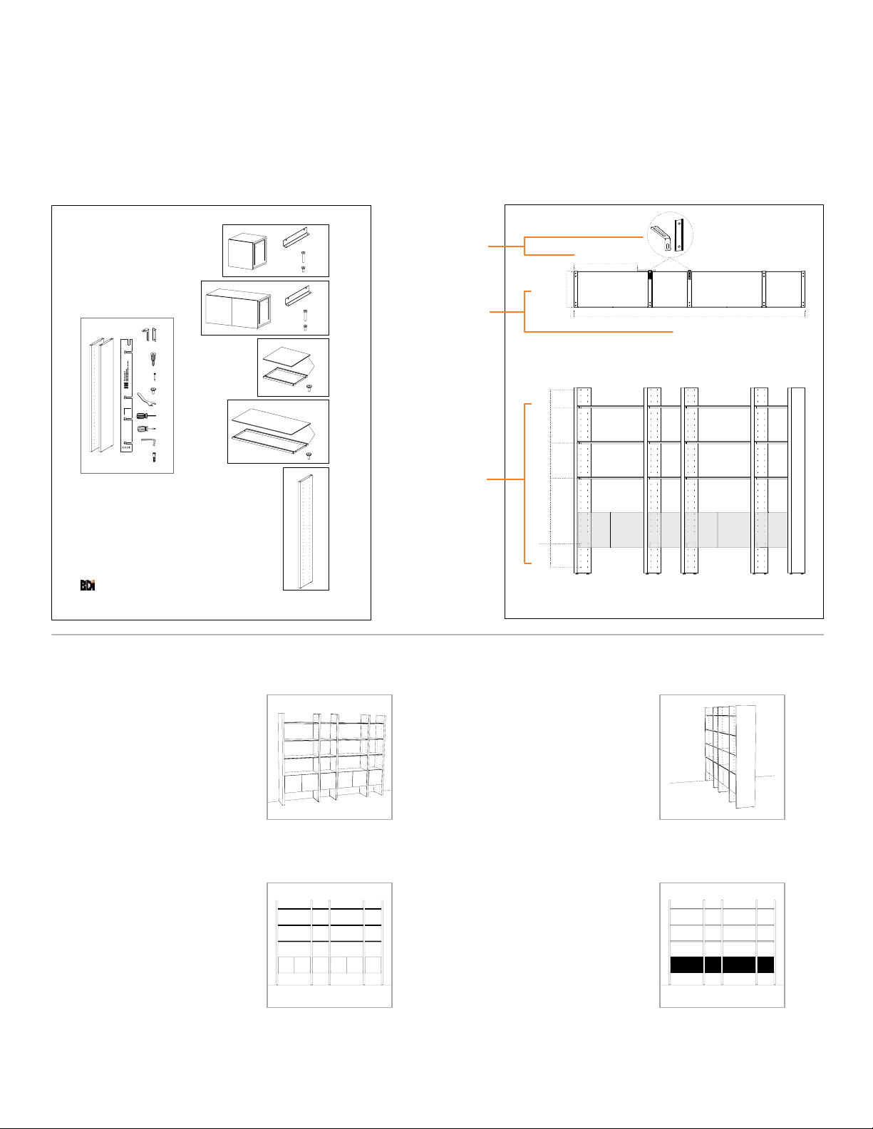
Locate the Package Reference Booklet
3
See page 2 to identify all components.
For missing hardware pieces, please
contact BDI Customer Service at
customerservice@bdiusa.com. For all
other concerns, please contact your BDI
Retailer.
Component List
15020
Package Reference
x 2
A B
C x 4
Sample
D x 4
E x 4
x 1
F x 1
G x 1
H x 1
I x 1
X x 4
15010
15011
15000
15001
15025
See page 3 for a representation of your
Package containing critical information for
its assembly.
Model Details
J x 2
x 2
K x 4
L x 8
J x 2
x 2
K x 4
L x 8
x 1
x 6
E x 4
x 6
x 1
E x 4
Wall Bracket
Placement & Details
Overall
Dimensions
27.25 in
69.3 cm
to Bracket Template
15.625 in
39.7 cm
Package Reference
Hole
Spaces
4
6
6
Sample
Shelf & Cabinet
Location
11
x 3
Cabinet
Bracket
J
5
x2
Single Spacing
TOP VIEW
100 in
254 cm
2
WALL SYSTEM
PAGE 4
SHELF ASSEMBLY
PAGE 14
ROOM DIVIDER
PAGE 10
CABINET ASSEMBLY
PAGE 17
3
3
Page 4
WALL SYSTEM
Assembly Sequence
Overview
4
F
Level each Panel as it is being assembled. Use Leveler Wrench (F) to adjust the
height of the Panel, if necessary.
Page 5
Plan Ahead.
33
554466
66
HoleHole
TOP VIEWTOP VIEW
27.25 in27.25 in
69.3 cm69.3 cm
to Bracket Tto Bracket T
emplateemplate
15.625 in15.625 in
39.7 cm39.7 cm
100 in100 in
254 cm254 cm
Single SpacingSingle Spacing
x2x2
JJ
Model DetailsModel DetailsModel Details
To plan unit placement, refer to
Package Reference Booklet for
critical dimensions.
The assembled unit CANNOT
be moved, so carefully plan the
!
placement of the unit prior to
building.
1:
See the Bracket Template spacing
dimension on page 3 of the Package
Reference Booklet. Using the provided
spacing dimension, measure from the
edge of where the left End Panel will
be placed and mark the wall to indicate
placement of the bracket template.
Model Details
15.625 in
39.7 cm
27.25 in
69.3 cm
to Bracket Template
x2
Single Spacing
TOP VIEW
100 in
254 cm
Package Reference
Hole
Spaces
SpacesSpaces
4
6
6
Sample
Note:
Future placement of left End Panel
11
Cabinet
J
Bracket
5
WALL SYSTEM
3
5
Page 6
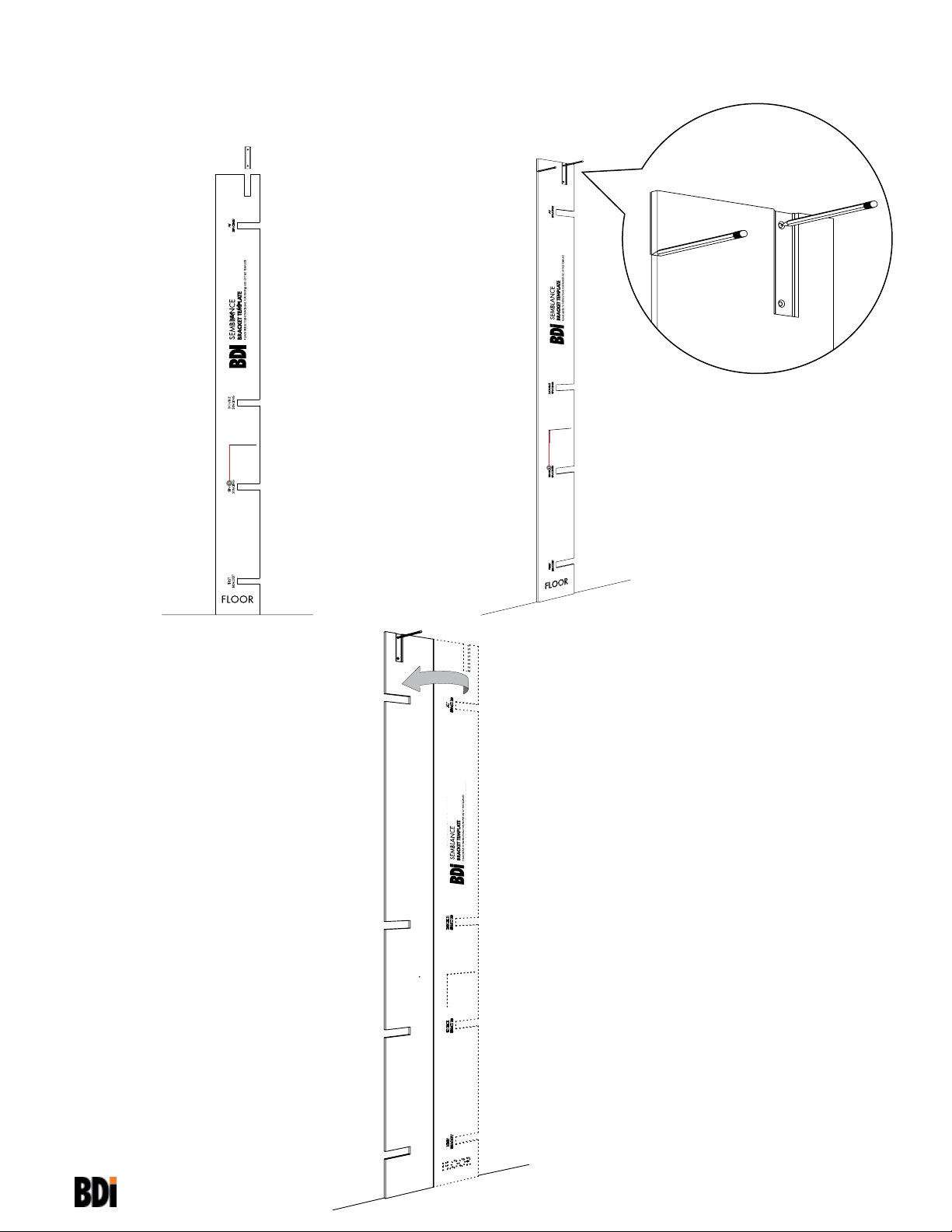
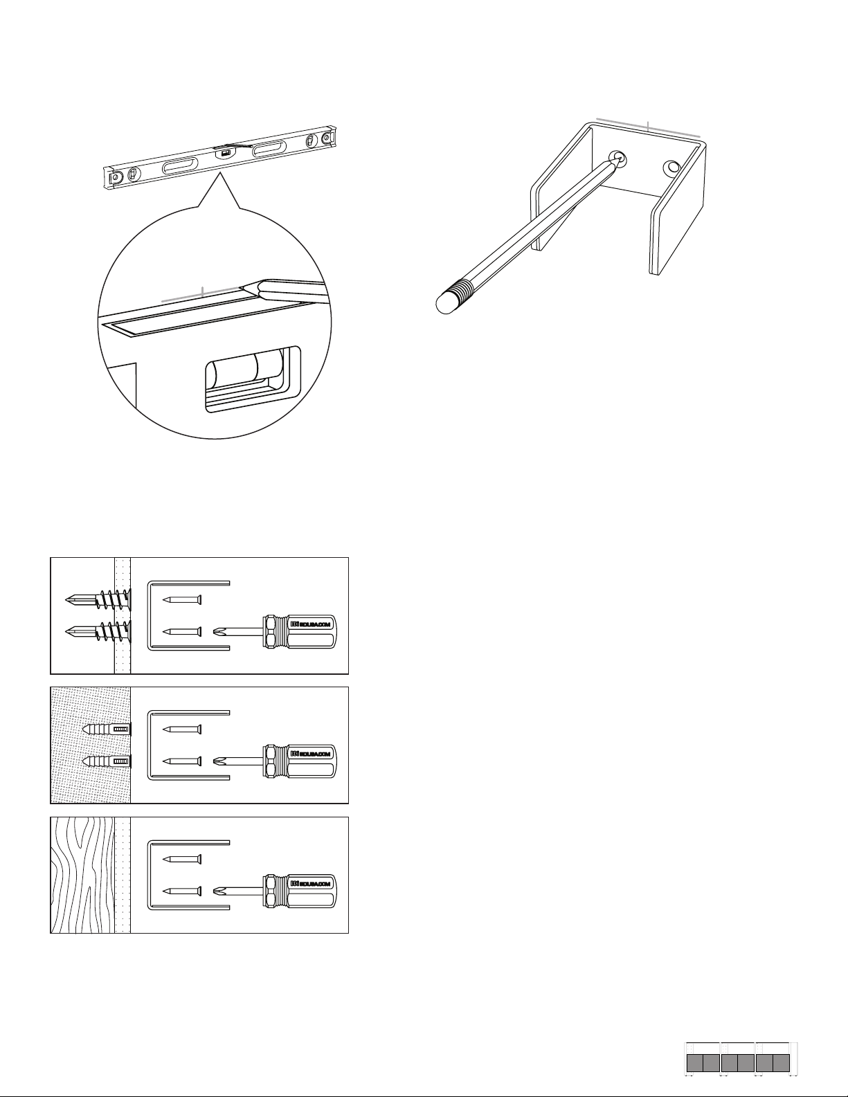
2:
Align the left side of the Bracket
Template with the wall mark. Level the
Template with the string, and insert
Wall Bracket (B) into its designated
groove. Mark the wall at bracket holes
to locate fastener locations.
B
3:
B
4:
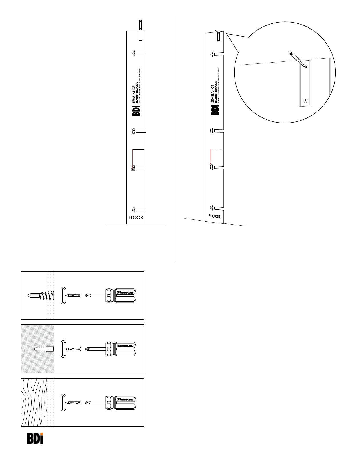
Attach first Bracket to the wall using
the appropriate attachment method
illustrated below.
C
X
D
B
D
B
D
B
H
Sheet Rock: (C) Drywall Anchors
(B) Bracket
(D) Screws
Concrete/Brick: (X) Plastic Concrete Anchors
(B) Bracket
H
H
(D) Screws
A
Power Drill is required for
pilot holes.
Wooden Beam: (B) Bracket
(D) Screws
1
/4" masonry drill bit and
6
Page 7
5:
Refer to Package Reference Booklet
for the number of recommended Wall
Brackets.
If 1 Bracket, skip to step 9 on page 8.
If 2 Brackets, proceed to step 6 and
finish the Wall System section of the
instructions.
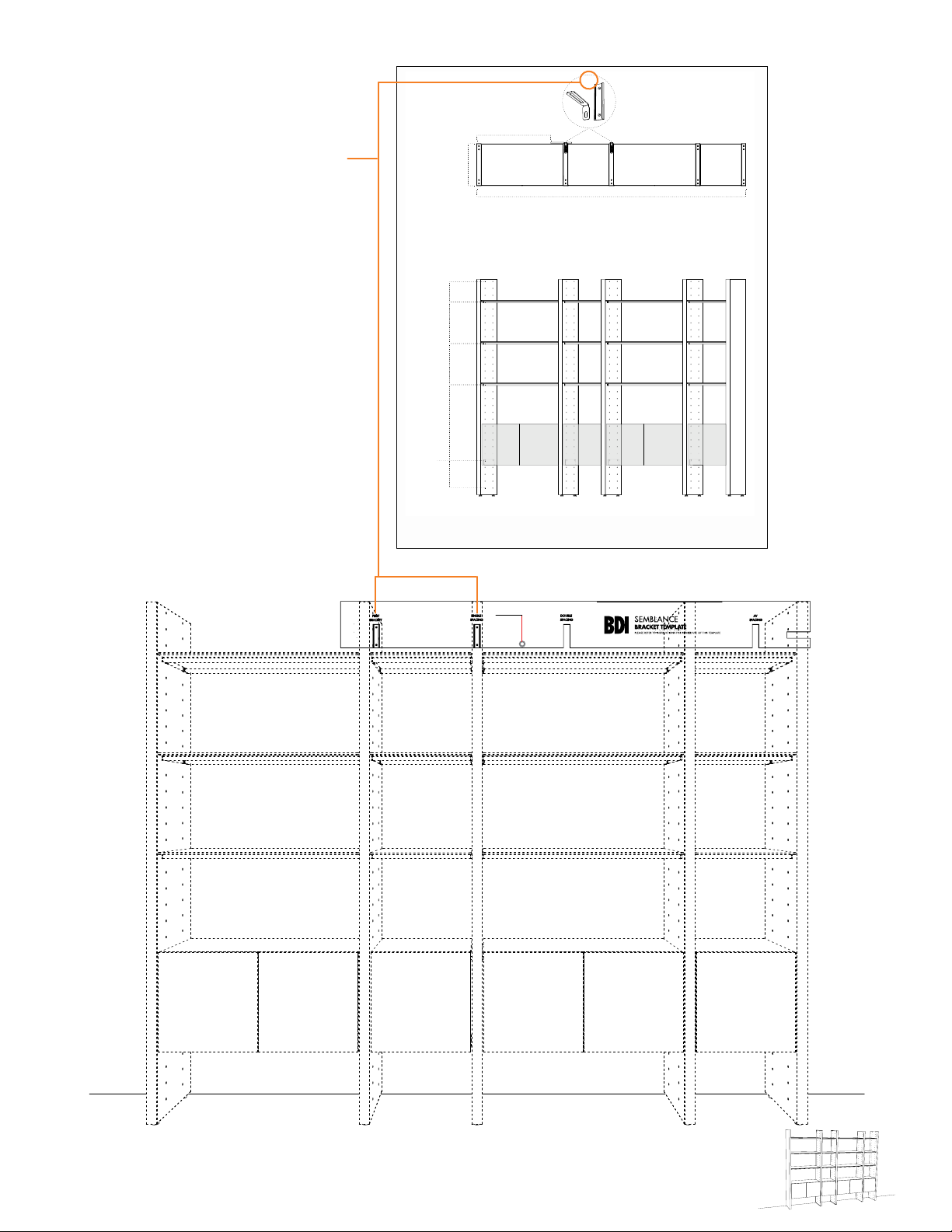
6:
Use the Bracket spacing groove that is
determined by your Package Reference
Booklet (2 of 2), to locate the second
Bracket.
Model Details
15.625 in
39.7 cm
27.25 in
69.3 cm
to Bracket Template
x2
Single Spacing
TOP VIEW
100 in
254 cm
Package Reference
Cabinet
Bracket
Hole
Spaces
4
6
6
11
J
5
Sample
3
WALL SYSTEM
7
Page 8
7:
Slip the Template over the attached
Bracket (B). Level the Template with
the string and mark second Bracket
hole locations on wall.
8:
Refer to Step 4 on page 6 to attach
second Bracket (B)
B
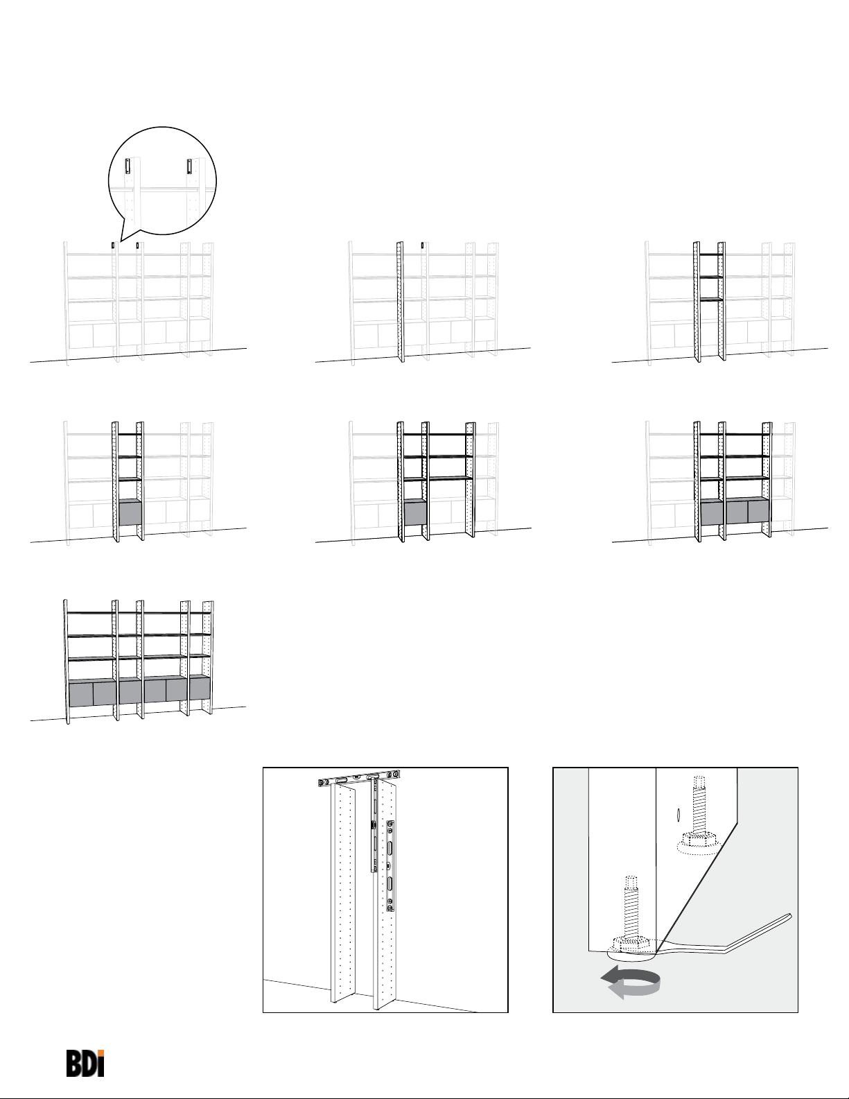
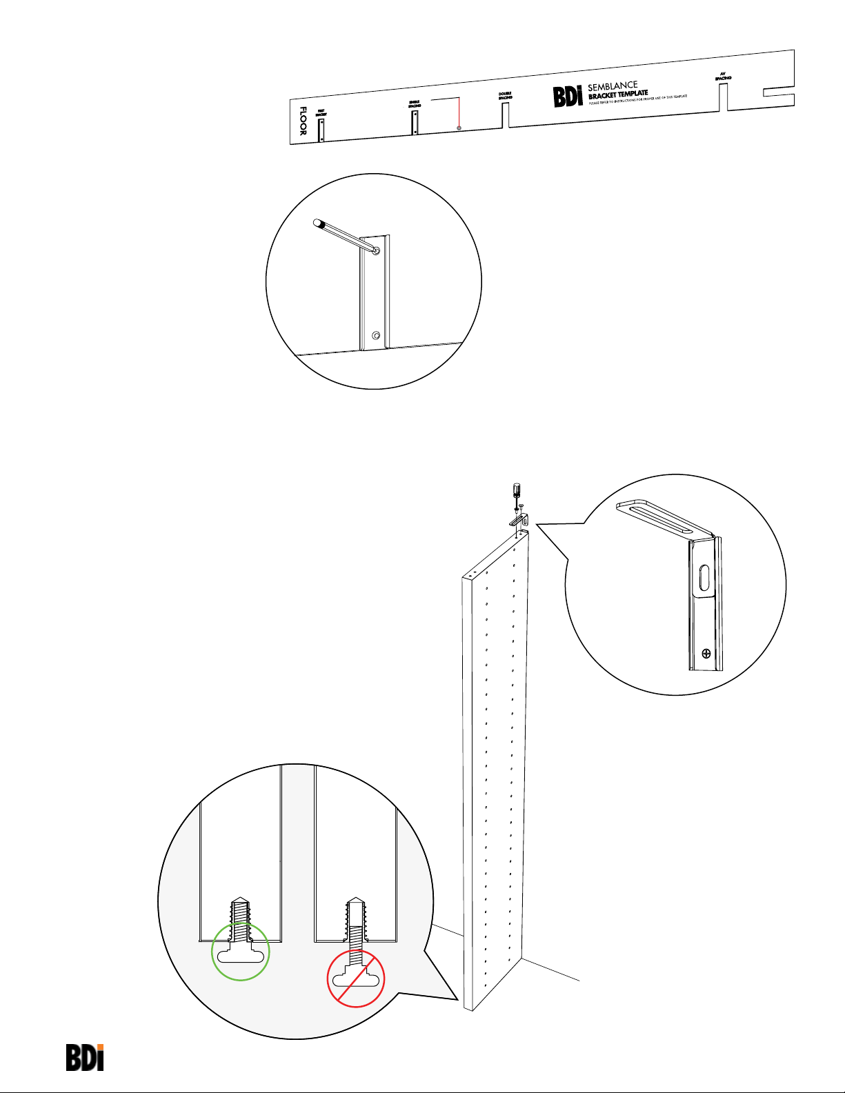
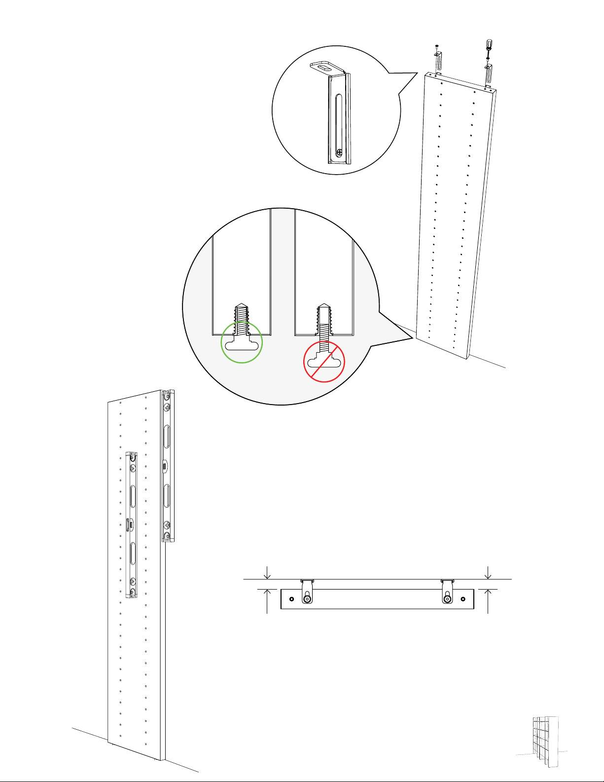
9:
Bring Divider Panel up to Bracket (B)
and slide Metal Insert (A) into Bracket
with the long flange exposed as shown.
Attach Metal Insert (A) to top of Panel
with Screws (E).
A
B
8
8
Page 9

10:
TOP VIEW
90
For next step turn to
SHELF ASSEMBLY
PAGE 14
WALL SYSTEM
9
9
Page 10

ROOM DIVIDER
Assembly Sequence
Overview
10
F
F
Level each Panel as it is being assembled. Use Leveler Wrench (F) to adjust the
height of the Panel, if necessary.
Page 11

Plan Ahead.
To plan unit placement, refer to
Package Reference Booklet for
critical dimensions.
The assembled unit CANNOT
be moved, so carefully plan the
!
placement of the unit prior to
building.
1:
Use the right edge of the Bracket Template
to locate the right side of the attached End
Panel.
equal
ROOM DIVIDER
11
Page 12
2:
Leveling the Template with the string,
insert Wall Bracket (B) into designated
groove.
B
3:
Mark Bracket hole location on wall and
mark the left edge of the Template on the
wall.
B
4:
Flip Template over and align right side of
Template with wall mark to locate second
Bracket position. Mark second Bracket
hole location lightly on wall and then install
Bracket.
12
Page 13
5:
Refer to Step 4 on page 6 to attach both
Brackets.
6:
Bring End Panel up to attached Bracket
(B) and slide Metal Insert (A) into Bracket
(B) with the short flange exposed as
shown. Attach Metal Insert (A) to top of
Panel with Screws (E).
E
A
B
G
A
B
7:
Make sure the Panel’s ends are the
same distance from the wall.
TOP VIEW
dd
ROOM DIVIDER
13
Page 14

SHELF ASSEMBLY
1:
Refer to Package Reference Booklet for
the hole positions of the Shelf Screws (E).
2:
Model Details
15.625 in
39.7 cm
27.25 in
69.3 cm
to Bracket Template
x2
Single Spacing
TOP VIEW
100 in
254 cm
Package Reference
Cabinet
Bracket
Hole
Spaces
4
6
6
11
J
5
Sample
3
PANEL
SHELF
E
PANEL
14
SHELF
Page 15

3:
Use the appropriately sized Shelf Frame as
a spacing guide for the next Panel. Lay the
Frame on the floor beside the fixed Panel
and bring the next Panel up to the Shelf
Frame.
Refer to the Package Reference Booklet
for spacing of each set of Panels.
4:
SHELF ASSEMBLY
15
Page 16

5:
Slide Metal Insert (A) into attached Bracket
(B) with the long flange exposed as shown.
Attach Metal Insert (A) to top of Panel with
Screws (E).
6:
Gently tighten all Shelf Frames.
A
B
7:
Install Glass Shelves.
Micro-etched face up.
16
16
SHELF ASSEMBLY
Page 17

CABINET ASSEMBLY
1:
Refer to Package Reference Booklet for
Cabinet Bracket positions.
Model Details
27.25 in
69.3 cm
to Bracket Template
x2
Single Spacing
TOP VIEW
15.625 in
39.7 cm
100 in
254 cm
Package Reference
2:
Screw Cabinet Brackets (J) into
determined inserts.
Cabinet
J
Bracket
Hole
Spaces
4
6
6
11
5
Sample
3
J
L
G
CABINET ASSEMBLY
17
17
Page 18

3:
Slide Cabinet in between panels, well
above the Bracket, and carefully lower into
place so that Cabinet Bracket fits into the
recess on cabinet’s bottom side.
18
CABINET
PANEL
PANEL
CABINET
Page 19
4:
K
5:
L
After completing the assembly of
Bracketed Panels, repeat Shelf and
Cabinet Assembly for each consecutive
Panel until your Package is complete.
CABINET ASSEMBLY
19
Page 20

2.
3.
1.
*2.
*2.
B
B
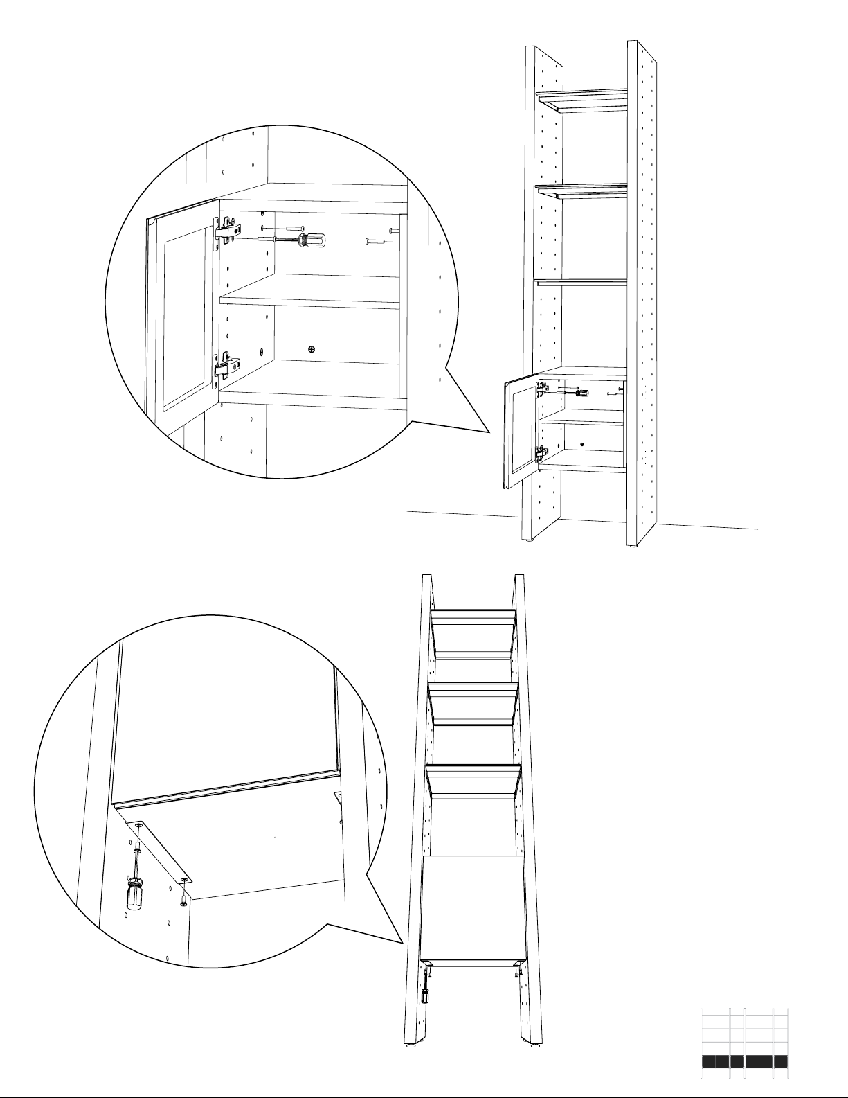
ADJUST DOOR HINGES (IF NEEDED)
If the cabinet’s door appears out of alignment, this can be corrected with
3.
1.
minor adjustment on each door.
Because these hinges are infinitely adjustable, adjusting one hinge element
can sometimes cause the need for adjustments to other elements. But with
a few adjustments, you can modify the orientation of the cabinet door to
make sure that it hangs evenly.
Use a Phillips screwdriver to adjust cabinet’s door hinges:
• By adjusting Screw 1, the door will move LEFT or RIGHT within the
frame. Make minor adjustments at both top and bottom hinges for
best results.
• By adjusting Screw(s) 2, the door will move UP or DOWN within
the frame (the top and bottom hinges must be adjusted the same
degree).
NOTE: Loosen Screws 2 one complete turn, raise or lower door, then hold
in position while tightening Screws 2 (on both hinges).
• By adjusting Screw 3 the entire door will move IN or OUT, opening
or closing the gap between the doorframe and cabinet. (This screw
rarely needs adjustment.)
REVERSE DOOR-SWING (IF DESIRED)
A
The Single Cabinets feature a reversible door assembly so that you can
open either from the left or the right.
To reverse the door’s orientation,
1. Remove the Door by actuating both of its quick-release hinges (A);
carefully place the detached Door aside.
2. Using a Philips head screwdriver, remove both Hinge Plates from
the interior wall of the cabinet by loosening the screws holding it in
place (B).
3. Install both Hinge Plates to the opposite interior wall at the
pre-determined locations.
4. Re-install the Door by connecting each Door Hinge to the relocated
Hinge Plates.
Helpful Tips for Designing your own Semblance Package.
CABINET CABINET
CABINET
7 inserts
The Cabinet Bracket Screw must be 1
space hole above the Shelf Screw to
align Cabinet bottom with the top of a
Shelf.
20
Designed by Matthew Weatherly. These distinctive product configurations are protected by US and international patents, trade dress, and/or copyright laws.
BDI are trademarks of Becker Designed, Inc. All Rights reserved. ©2013, BDI Assembled in the US from parts of foreign origin. REV061413v2
There is a 7 insert spacing pattern to
align Shelves with top and bottom of a
Cabinet.
There is a 3 insert spacing pattern, from
Cabinet Bracket to Shelf Frame, to
align Shelves with middle of a Cabinet.
3 inserts
Page 21
Low Semblance System
Your SEMBLANCE System Furniture is
engineered for easy assembly.
Carefully follow this procedure to prevent
any damage.
Placement and
Maintenance
SEMBLANCE System Furniture is
designed for indoor use on level floors.
Clean glass with glass cleaner, steel parts
and wood veneer with a moist cloth.
You will need:
32"
Which Low Semblance unit are you building?
If the unit consists of any tall panels, BDI
recommends installing a Wall Bracket
supplied in any 15020 or 15021 End
panel packaging.
Refer to Main
Assembly Instructions
for Wall Bracket
installation as well as
shelf and cabinet
assembly.
If the Low unit consists of any Cabinets,
Drawers, or Desks you are not required
to install a U-Bracket.
If the Low unit consists of
ONLY shelves you MUST
install a U-Bracket supplied
in any 15023 End Panel 29
packaging. This configuration CANNOT
be oriented as a room divider.
Refer to Main Assembly Instructions
for proper assembly of shelves and
cabinets.
LOW SEMBLANCE
Instructions are
inside for proper
installation for
U-Bracket.
1
Page 22

Plan Ahead.
To plan unit placement, refer to
Package Reference Booklet for
critical dimensions.
1:
Select the shelf spacing below that reflects
the far left bay of your unit (Double-Wide
or Single-Wide)
!
The assembled unit CANNOT
be moved, so carefully plan the
placement of the unit prior to
building.
Double-Wide:
33 in / 837 mm
2:
Using the selected spacing dimension
above, measure from the outside edge of
where the left End Panel will be placed
and mark the wall to indicate the Divider
Panel’s location.
Single-Wide:
17.75 in / 452 mm
3:
Measure from the mark near the floor
using the illustrated dimension below.
Make a vertical line on the wall to indicate
the center line of the U-Bracket.
2
Note:
Future placement of left End Panel
27
/ 686
in
mm
Page 23
4:
Using a level, mark a short horizontal
line no longer than 1.25 in / 31 mm that
inersects the U-Bracket’s center line.
5:
Align the edge of the U-Bracket with the
existing wall marks and mark the hole
locations on the wall.
6:
Attach the U-Bracket to the wall using the
appropriate attachment method illustrated
below
D
C
W
D
X
W
D
H
Sheet Rock: (C) Drywall Anchors
(W) Bracket
(D) Screws
Concrete/Brick: (X) Plastic Concrete Anchors
(W) Bracket
(D) Screws
H
A
1
/4" masonry drill bit and
Power Drill is required for
pilot holes.
H
Wooden Beam: (W) Bracket
(D) Screws
W
LOW SEMBLANCE
3
Page 24

7:
Slide the Divider Panel into the
U-Bracket.
8:
Refer to Main Assembly Instructions
for proper assembly of shelves and
cabinets.
4
Level each Panel as it is being assembled. Use Leveler Wrench (F) to adjust the
height of the Panel, if necessary.
SHELF ASSEMBLY
PAGE 14
CABINET ASSEMBLY
PAGE 17
 Loading...