

Page 1

HIGH PERFORMANCE
FURNITURE FOR YOUR
HOME THEATER
TM
Avion
8540-1
Assembly Instructions
Page 2

Avion™ Home Theater Furniture
www.bdiusa.com
customerservice@bdiusa.com
Your Avion
™
Home Theater Furniture
is engineered for easy assembly.
Carefully follow this procedure to
prevent any damage.
Placement and Maintenance
Avion™ Model 8540-1 is designed
to be compatible with Model
8527/8537 (Triple-Wide Cabinets)
or Model 8529/8539 (Quad-Wide
Cabinets). Clean steel parts with a
moist cloth.
Plasma Mounting Blister Pack
Phillips Head Mounting Screws
(The following thread sizes are
included:
M4, M5, M6, M8.)
Horizontal Mounting Bar x 2
C2
C1
Horizontal Mounting Brackets
Black Washer x 8
B1
Support Tube x 2
Spacers x 8
(Large & Small)
Avion Construction Blister Pack
A - 1 1/2” Button Head Screw x 2
D - Black Pan Head Screw x 8
B2
E - Black Nut x 8
Flanged Nut x 4
Unpack and identify the parts listed above.
The assembly workspace should be a clean, non-marring surface such as carpet. For missing hardware pieces, please contact BDI
Customer Service at: customerservice@bdiusa.com For all other concerns please contact your local BDI Retailer.
Step 1
Install Horizontal Mounting Bars. Find the mounting screws that were supplied with your flat-screen TV. If such screws are not
available, find the short Phillips head mounting screws provided in the Plasma Mounting Blister Pack that thread cleanly into
the mounting holes in the back of your TV. Attach upper and lower horizontal mounting bar to your TV, as shown, using
washers and Phillips driver. Note: If back of TV has a curved surface or if bars do not rest flat, use spacers and long mounting
screws provided. Make sure bars are centered, left to right. Fully tighten bars to TV!
Flat Screen TV
Universal Mounting Bar
(back view)
Short Mounting
Screw
Designed by BDI Design Studio.
‘Avion’ is a trademark of Becker
Designed, Inc. All rights reserved.
©2006 Becker Designed, Inc.
Washer
Page 3

Step 2
Install both support tubes (B1 and B2)
through the holes on the top panel of the Avion
cabinet, and fasten them from the underside
of the cabinet using the (A) 1 1/2” button
head screws as shown.
B1
B2
Step 3
Install both horizontal mounting
brackets (C1 and C2) to the inside section
of the support tubes using the (D) black nuts
and (E) black pan head screws as shown
to the right.
Note: You may raise or lower the position of
the horizontal mounting brackets depending on
the desired television height.
Note: Lower opening face
towards center of unit.
C1
C2
Page 4
Step 4
Install TV with attached horizontal mounting bars to
horizontal mounting brackets at desired height by
inserting the threaded studs into key holes. Note: Flanged
nuts are provided in the Plasma Mounting Blister Pack and
must be threaded on the studs of the upper mounting bar
in order to prevent any damage to the TV.
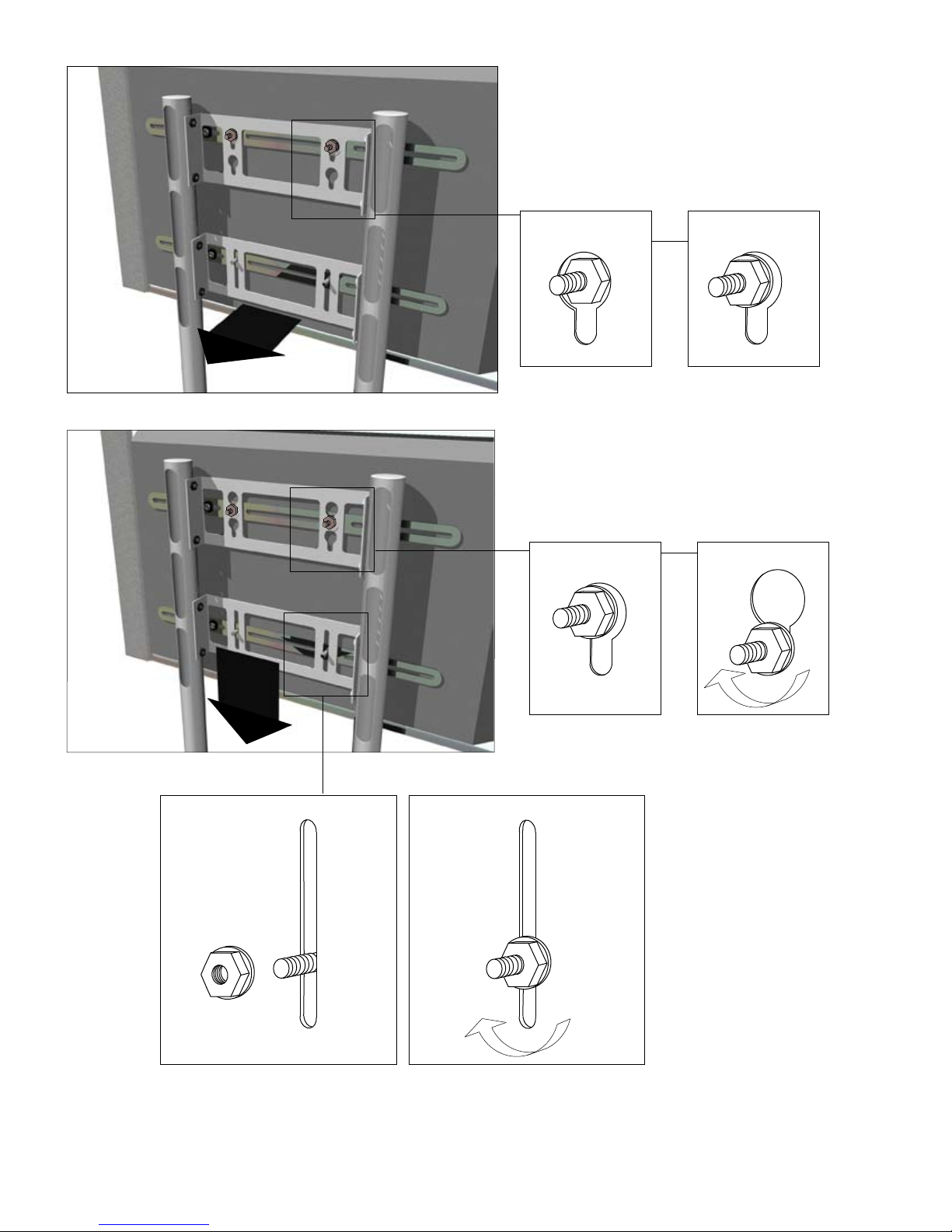
Step 5
Once the threaded post are positioned through the key holes
and slots, lower TV into resting position. Tighten flanged
nuts on upper mounting bar.
Install the second set of flanged nuts to the threaded posts of the lower
mounting bar. Once positioned, fully tighten all flanged nuts!
 Loading...