

Page 1

LINEA
SHELVING
INSTRUCTION MANUAL
™
5801(A)/5802(A)
LET’S GET STARTED.
DESIGN MATTHEW WEATHERLY
Page 2

Page 3

Congratulations on purchasing your Linea Shelving 5801(A) / 5802(A) from BDI. Your
shelving has been designed to provide a lifetime of enjoyment. This manual will provide
you with assembly instructions and other helpful information to ensure that you get the
most out of your shelving. Please save it for future reference.
Your Linea shelving has been engineered for simple assembly. Please follow these
directions carefully to prevent any damage.
Should you need further assistance, contact BDI at customerservice@bdiusa.com.
ENJOY!
BDIUSA.COM | 3NEED ASSISTANCE? customerservice@bdiusa.com
Page 4

HARDWARE AND COMPONENTSHARDWARE AND COMPONENTS
Unpack and identify the parts listed below. Note that some components are shipped inside the
cabinet. The assembly workspace should be a non-marring surface such as carpet. For missing
hardware pieces, please contact BDI Customer Service at customerservice@bdiusa.com.
Do not use power tools for the assembly of this product.
For all other concerns, please contact your BDI retailer.
PART #
DESCRIPTION
QUANTITY
PART #
DESCRIPTION
QUANTITY
PART #
DESCRIPTION
TI
Phillips Screwdriver
1
C3
Cabinet Block
2 per unit
H3
Wooden Dowel
PART #
DESCRIPTION
QUANTITY
PART #
DESCRIPTION
QUANTITY
PART #
DESCRIPTION
T2
Hex Driver
1
H1
M6 x 30mm Screw
12 per unit
H4
Barrel Nut
PART #
DESCRIPTION
QUANTITY
PART #
DESCRIPTION
QUANTITY
PART #
DESCRIPTION
T3
Leveler Wrench
1
H2
Cam Bolt
4 per unit
H11
Shelf Pin
QUANTITY
4 | BDIUSA.COM LINEA 5801(A) / 5802(A)
8 per unit
QUANTITY
4 per unit
QUANTITY
16 per unit
Page 5

HARDWARE AND COMPONENTS
Holes on 1 side Holes on 2 sides
PART #
DESCRIPTION
QUANTITY
PART #
DESCRIPTION
End Panel
2 per Base Unit
5801/5801A
5802/5802A
Top Panel
C1
C4
PART #
DESCRIPTION
QUANTITY
1 per extension unit
C2
Inner Panel
5801/5801A 5802/5802A
PART #
DESCRIPTION
C5
Cabinet
QUANTITY
PART #
DESCRIPTION
QUANTITY
1 per unit
C6
Outer Glass Shelf
3 per unit
QUANTITY
PART #
DESCRIPTION
QUANTITY
1 per unit
C7
Inner Glass Shelf
1 per unit
BDIUSA.COM | 5NEED ASSISTANCE? customerservice@bdiusa.com
Page 6

HARDWARE AND COMPONENTSHARDWARE AND COMPONENTS
Wall Mounting Kit
PART #
DESCRIPTION
QUANTITY
PART #
DESCRIPTION
QUANTITY
H5
Wall Bracket
2
H8
Sheetrock Anchor
4
PART #
DESCRIPTION
QUANTITY
PART #
DESCRIPTION
QUANTITY
H6
Cabinet Bracket
2
H9
Plaster/Block Anchor
4
PART #
DESCRIPTION
QUANTITY
PART #
DESCRIPTION
QUANTITY
H7
Fastener Screw
4
H10
Bracket Screw
2
6 | BDIUSA.COM LINEA 5801(A) / 5802(A)
Page 7

SINGLE OR MULTIPLE UNITS
Linea can be configured as stand-alone units or multiple combinations of narrow and wide units.
GO TO PAGE 8 GO TO PAGE 20
5801 5802
5801/5802 + 5801A/5802A
or other multi-unit combinations
BDIUSA.COM | 7NEED ASSISTANCE? customerservice@bdiusa.com
Page 8
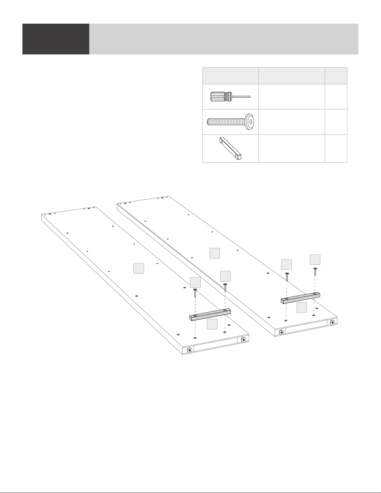
STEP 1. ATTACH CABINET BLOCKS TO END PANELSASSEMBLY
Attach 1 (C3) Cabinet Block to each (C1) End
Panel using (H1) Screws and (T2) Hex Driver.
PART/DESCRIPTION QTY
T2-HEX DRIVER 1
H1-SCREW 4
C3-CABINET BLOCK 2
C1
H1
C3
C1
H1
Lower End
H1
H1
C3
8 | BDIUSA.COM LINEA 5801(A) / 5802(A)
Page 9

STEP 2. INSTALL CAMS AND DOWELS
ASSEMBLY
Find the sets of 3 holes near the top edge of the
(C1) Side Panels. Screw (H2) Cam Bolts into the
threaded holes using (T1) Phillips Screwdriver and
push (H3) Wooden Dowels into the outer holes.
Lower End
C1
C1
PART/DESCRIPTION QTY
T1-PHILLIPS
SCREWDRIVER
1
H2-CAM BOLT 4
H3-WOODEN DOWEL 8
H3
H2
H3
H3
H2
H3
BDIUSA.COM | 9NEED ASSISTANCE? customerservice@bdiusa.com
Page 10
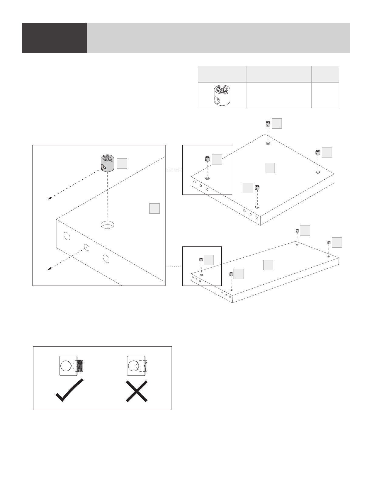
STEP 3. INSERT BARREL NUTSASSEMBLY
Insert 4 (H4) Barrel Nuts into the holes on the
top of the (C4) Top Panel, making sure that the
hole on the side of the barrel nuts align with the
holes on the edges of the panel.
H4
Align hole
C4
PART/DESCRIPTION QTY
H4-BARREL NUT 4
H4
H4
H4
C4
H4
5801
H4
H4
H4
H4
NOTE: Look into the side hole of the barrel nuts and
make sure, the set screw is not blocking the hole.
If the hole is blocked, unscrew set screw a few turns until
the hole is clear, which will allow the cam bolts to enter.
C4
5802
10 | BDIUSA.COM LINEA 5801(A) / 5802(A)
Page 11
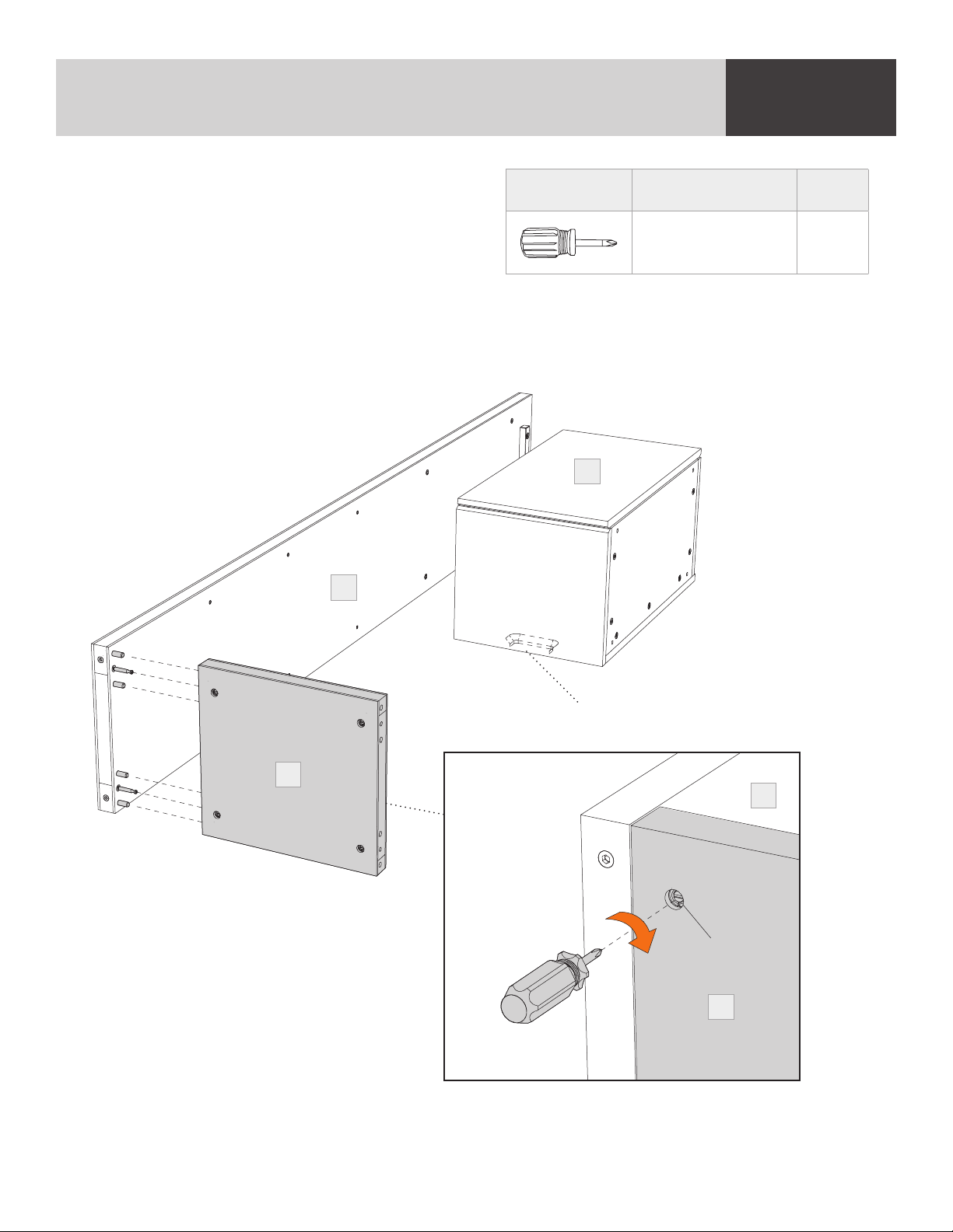
STEP 4. ATTACH TOP PANEL TO SIDE PANEL
ASSEMBLY
Attach (C4) Top Panel to (C1) End Panel by
sliding dowels and cam bolts into the holes on the
PART/DESCRIPTION QTY
edge of (C4) Top Panel. If cams don’t go into
barrel nuts, check to make sure the barrel nut is
aligned with the side hole and make sure the set
T1-PHILLIPS
SCREWDRIVER
1
screw is loosened before insertion of the cam bolts.
Tighten barrel nuts using (T1) Phillips Screwdriver with a clockwise turn. Position (C5) Cabinet as
shown. Make sure rectangular opening on back of cabinet is facing upward towards (C4) Top Panel.
Make sure the door is facing upward.
Door(s) up
C5
C1
C4
Holes on this side
Rectangular opening here
C1
Barrel nut
C4
BDIUSA.COM | 11NEED ASSISTANCE? customerservice@bdiusa.com
Page 12
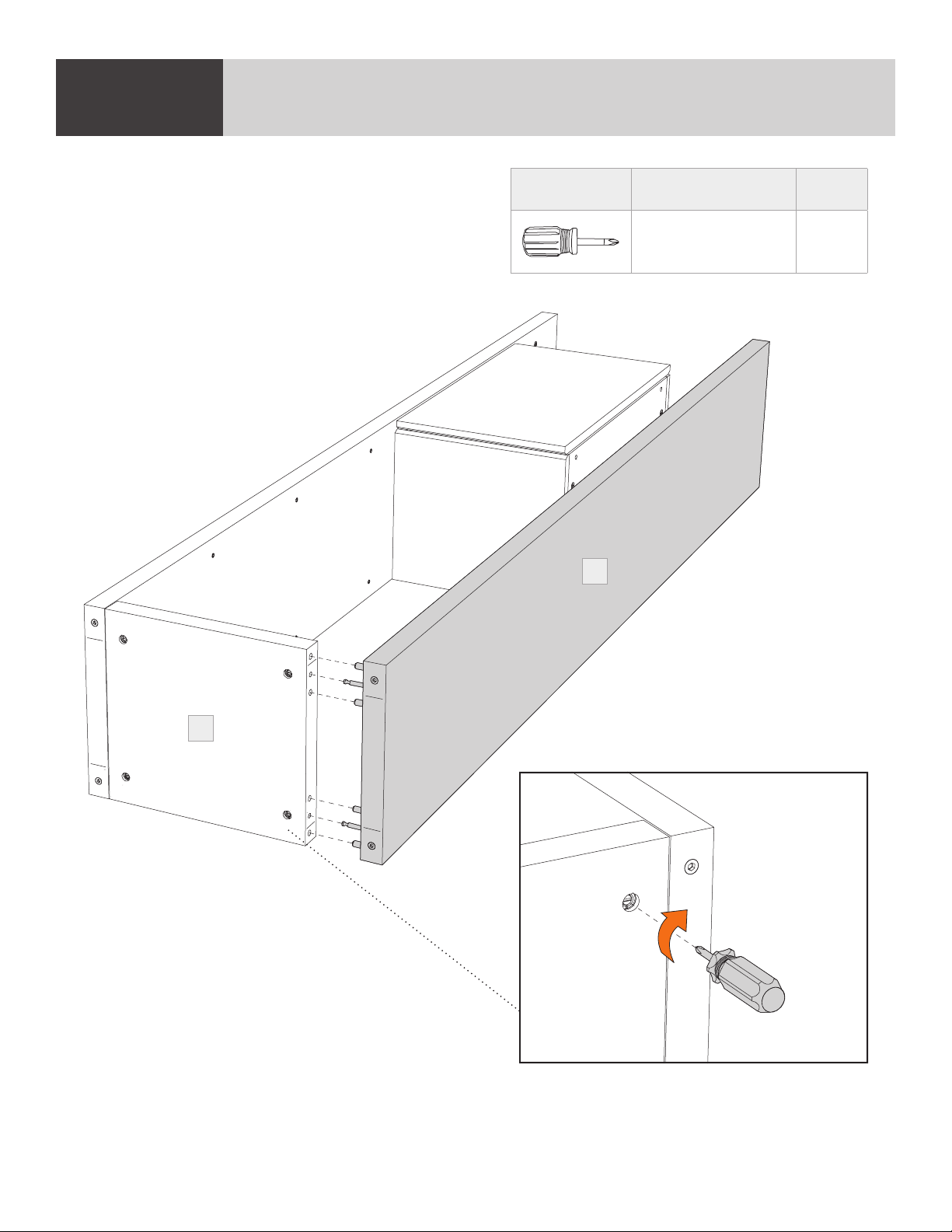
STEP 5. ATTACH SECOND END PANELASSEMBLY
Attach the next (C1) End Panel to the other side of
(C4) Top Panel by sliding dowels and cams into the
holes on the side of (C4) Top Panel. Tighten barrel
nuts using (T1) Phillips Screwdriver.
C1
PART/DESCRIPTION QTY
T1-PHILLIPS
SCREWDRIVER
1
C4
12 | BDIUSA.COM LINEA 5801(A) / 5802(A)
Page 13

STEP 6. ATTACH CABINET TO END PANELS
ASSEMBLY
Making sure the bottom of the cabinet is against
the (C3) Cabinet Blocks, carefully open the
cabinet door and attach the (C5) Cabinet to
(C1) End Panels using 8 (H1) Screws and tighten
with (T2) Hex Driver.
C1
C1
C5
PART/DESCRIPTION QTY
T2-HEX DRIVER 1
H1-SCREW 8
C3
H1
H1
H1
C5
C1
H1
H1
C1
H1
BDIUSA.COM | 13NEED ASSISTANCE? customerservice@bdiusa.com
Page 14

2 PERSON TASK
STEP 7. STAND UP / WALL CONNECTIONASSEMBLY
With help from another person, carefully stand the cabinet onto its base. Carefully walk it into position.
Attaching your Linea shelving to the wall is required to ensure your safety. Use painter’s tape to
mark both upper back corners of the unit, as shown.
Painter’s tape
14 | BDIUSA.COM LINEA 5801(A) / 5802(A)
Page 15

STEP 8. WALL CONNECTION (continued)
ASSEMBLY
Move the cabinet to the side. Place (H5) Wall
Brackets on the wall (flush with top and 1/4"
(7mm) away from the edge) and mark hole
locations on the wall using a pencil. Drill holes at
these locations for wall inserts.
Choose (H8) or (H9) Wall Anchors appropriate
for your wall type.
H5
1/4"
7mm
PART/DESCRIPTION QTY
H5-WALL BRACKET 2
H7-SCREW 4
H8-ANCHOR 4
H9-ANCHOR 4
Choose wall anchors based on your walls:
H8
H9
Sheetrock Anchor
Plaster/Brick/Block Anchor
Insert (H8) or (H9) Wall Anchors into the holes and attach (H5) Wall Brackets to the wall using
(H7) Anchor Screws.
H8/H9
H7
H5
H8/H9
H7
BDIUSA.COM | 15NEED ASSISTANCE? customerservice@bdiusa.com
Page 16

2 PERSON TASK
STEP 9. WALL CONNECTION (continued)ASSEMBLY
Re-position your Linea cabinet in front of the
(H5) Wall Brackets. Stand on a step ladder and
slide (H6) Cabinet Brackets down into the slot in
(H5) Wall Brackets and tighten using (H10) Bracket
Screws and (T2) Hex Driver.
H10
H6
PART/DESCRIPTION QTY
T2-HEX DRIVER 1
H6-CABINET BRACKET 2
H10-BRACKET SCREW 2
H10
H6
16 | BDIUSA.COM LINEA 5801(A) / 5802(A)
Page 17

STEP 10. INSTALL SHELVES AND LEVEL
ASSEMBLY
Attach 16 (H11) Shelf Pins into the threaded holes
using a (T1) Phillips Screwdriver—choose preferred
interior shelf height. Install (C6) Outer Glass
Shelves on the shelf pins, tilting the glass slightly
to avoid hitting side panels. Tilt and install (C7)
Inner Glass Shelf inside the cabinet.
Use (T3) Leveler Wrench to level the cabinets.
H11
T1
PART/DESCRIPTION QTY
T1-PHILLIPS
SCREWDRIVER
1
T3-LEVELER WRENCH 1
H11-SHELF PIN 16
C6
C6
T3
C6
C7
BDIUSA.COM | 17NEED ASSISTANCE? customerservice@bdiusa.com
Page 18

CHOOSE DOOR POSITIONFINE TUNING
The door on your Linea 5801 Cabinet can be
attached to the opposite side (if desired), allowing
the door to swing to the right. Remove the 2 screws
holding each hinge plate to the side of the cabinet
using (T1) Phillips Screwdriver and flip the door
(top becomes bottom) and attach to the threaded
holes on the opposite side using the same screws.
Proceed to page 30.
PART/DESCRIPTION QTY
T1-PHILLIPS
SCREWDRIVER
1
ASSEMBLY
18 | BDIUSA.COM LINEA 5801(A) / 5802(A)
Page 19

CONFIGURATIONS
Endless Possibilities
Linea can be configured in endless ways. Below are a few examples. Configurations up to 3 units
wide may be assembled on the floor, stood up and carefully positioned. It is also possible to
assemble 1 unit, stand it up, and add additional units to it. Every configuration requires 1 base unit
and then additional units. Base units come with 2 end panels, and each add on unit always includes
1 inner panel.
5801 + 5802A +5801A
5801 + 5801A 5802 + 5802A
5801 + 5802A 5802 + 5801A
BDIUSA.COM | 19NEED ASSISTANCE? customerservice@bdiusa.com
Page 20

HARDWARE AND COMPONENTSHYBRID KIT
Hybrid Assembly
The following pages will show how to assemble a kit of 2 units shown below—which is a 5802 and a
5801A. Your configuration may differ, but the assembly method will be the same.
End Panel
Inner Panel
End Panel
5802 (Base) + 5801A (Add-on)
20 | BDIUSA.COM LINEA 5801(A) / 5802(A)
Page 21

STEP 1. ATTACH CABINET BLOCKS TO PANELS
ASSEMBLY
Attach (C3) Cabinet Blocks to a (C1) End Panel
and a (C2) Inner Panel using (H1) Screws and
(T2) Hex Driver.
C2
C1
PART/DESCRIPTION QTY
T2-HEX DRIVER 1
H1-SCREW 4 per unit
C3-CABINET BLOCK 2 per unit
H1
H1
C3
H1
H1
H1
C3
C3
H1
BDIUSA.COM | 21NEED ASSISTANCE? customerservice@bdiusa.com
Page 22

STEP 2. INSTALL CAMS AND DOWELSASSEMBLY
Find the sets of 3 holes near the top edge of the
(C1) End Panel and (C2) Inner Panel. Screw
(H2) Cam Bolts into the threaded holes using (T1)
Phillips Screwdriver and push (H3) Wooden
Dowels into the outer holes.
C2
C1
PART/DESCRIPTION QTY
T1-PHILLIPS
SCREWDRIVER
1
H2-CAM BOLT 4 per unit
H3-WOODEN DOWEL 8 per unit
H2
H3
H3
H2
H3
H3
22 | BDIUSA.COM LINEA 5801(A) / 5802(A)
Page 23

STEP 3. INSERT BARREL NUTS
ASSEMBLY
Insert 4 (H4) Barrel Nuts into the holes on the
top of the (C4) Top Panel, making sure that the
hole on the side of the barrel nuts align with the
holes on the edges of the panel.
H4
Align hole
C4
PART/DESCRIPTION QTY
H4-BARREL NUT 4
H4
H4
H4
C4
H4
5801
H4
H4
H4
H4
NOTE: Look into the side hole of the barrel nuts and
make sure, the set screw is not blocking the hole.
If the hole is blocked, unscrew set screw a few turns until
the hole is clear, which will allow the cam bolts to enter.
C4
5802
BDIUSA.COM | 23NEED ASSISTANCE? customerservice@bdiusa.com
Page 24

STEP 4. ATTACH TOP PANEL TO PANELSASSEMBLY
Attach (C4) Top Panel to (C1) End Panel and
(C2) Inner Panel by sliding dowels and cam bolts
into the holes on the edge of (C4) Top Panel.
If cams don’t go into barrel nuts, check to make
sure the barrel nut is aligned with the side hole
and make sure the set screw is loosened before
insertion of the cam bolts.
Tighten barrel nuts using (T1) Phillips Screwdriver with a clockwise turn. Position cabinets as
shown. Make sure the door is facing upward.
Doors up
PART/DESCRIPTION QTY
T1-PHILLIPS
SCREWDRIVER
C1
1
C2
Barrel nut
C4
Holes on this side
C4
24 | BDIUSA.COM LINEA 5801(A) / 5802(A)
Page 25

STEP 5. ATTACH CABINET
ASSEMBLY
Making sure the bottom of the cabinet is against
the (C3) Cabinet Blocks, carefully open the
cabinet doors and attach the (C5) Cabinet to
(C1) End Panels and (C2) Inner Panels using
8 (H1) Screws per cabinet and tighten with
(T2) Hex Driver.
C1
PART/DESCRIPTION QTY
T2-HEX DRIVER 1
H1-SCREW 8
C2
H1
H1
C5
H1
H1
H1
C3
BDIUSA.COM | 25NEED ASSISTANCE? customerservice@bdiusa.com
Page 26

2 PERSON TASK
STEP 6. STAND UP / CONNECT TO WALLASSEMBLY
Painter’s
tape
6A-1: Inline Against Wall
Option A: With help from at least 1 other
person, carefully stand the cabinets onto
their base. Carefully lift and slide into
position flat along a wall.
6A-2: Inline Against Wall
Option A: Attaching your Linea Cabinet to
the wall is required to ensure your safety.
Use painter’s tape to mark at least 1 upper
back corner of the unit, as shown. It is
recommended to attach the 2 outer
corners of multiple units.
Painter’s
tape
6B-1: Perpendicular Variation
Option B: With help from at least 1 other
person, carefully stand the cabinets onto
their base. Carefully lift and slide into
position as a peninsula extending
perpendicular to a wall.
Option B: Attaching your Linea Cabinet to
Use painter’s tape to mark at least 1 upper
6B-2: Perpendicular Variation
the wall is required to ensure your safety.
back corner of the unit, as shown. It is
recommended to attach the 2 outer
corners of multiple units.
26 | BDIUSA.COM LINEA 5801(A) / 5802(A)
Page 27

STEP 7. WALL CONNECTION (continued)
ASSEMBLY
Move the cabinet to the side. Place (H5) Wall
Brackets on the wall (flush with top and 1/4"
(7mm) away from the edge) and mark hole
locations on the wall using a pencil. Drill holes at
these locations for wall inserts.
Choose (H8) or (H9) Wall Anchors appropriate
for your wall type.
H5
1/4"
7mm
PART/DESCRIPTION QTY
H5-WALL BRACKET 2
H7-SCREW 4
H8-ANCHOR 4
H9-ANCHOR 4
Choose wall anchors based on your walls:
H8
H9
Sheetrock Anchor
Plaster/Brick/Block Anchor
Insert (H8) or (H9) Wall Anchors into the holes and attach (H5) Wall Brackets to the wall using
(H7) Anchor Screws.
H8/H9
H7
H5
H8/H9
H7
BDIUSA.COM | 27NEED ASSISTANCE? customerservice@bdiusa.com
Page 28

2 PERSON TASK
STEP 8. WALL CONNECTION (continued)ASSEMBLY
Re-position your Linea cabinet in front of the
(H5) Wall Brackets. Stand on a step ladder and
slide one (H6) Cabinet Bracket down into the slot
in (H5) Wall Brackets and tighten using (H10)
Bracket Screws and (T2) Hex Driver. Save the
second (H5) Wall Bracket for the final unit in the
inline assembly.
Inline Against Wall
PART/DESCRIPTION QTY
T2-HEX DRIVER 1
H6-CABINET BRACKET 2
H10-BRACKET SCREW 2
H10
H6
H10
H6
H10
H6
Perpendicular
Variation
28 | BDIUSA.COM LINEA 5801(A) / 5802(A)
Page 29

STEP 9. ATTACH CABINET BLOCK(S) TO PANEL(S)
ASSEMBLY
Attach (C3) Cabinet Block to the next panel in
the series using (H1) Screws and (T2) Hex Wrench.
Note: If you assemble the final unit in the series,
this will be a (C1) End Panel. If you are attaching
additional units, this will be a (C2) Inner Panel.
Attach (C3) Cabinet Blocks and (H1) Screws to
both sides of the (C2) Inner Panel.
C1 or C2
PART/DESCRIPTION QTY
T2-HEX DRIVER 1
H1-SCREW 4 per unit
C3-CABINET BLOCK 2 per unit
H1
H1
C3
BDIUSA.COM | 29NEED ASSISTANCE? customerservice@bdiusa.com
Page 30

ASSEMBLY
STEP 10. INSTALL CAMS AND DOWELS
Find the sets of 3 holes near the top edge of the
panel. Screw (H2) Cam Bolts into the threaded
holes using (T1) Phillips Screwdriver and push
(H3) Wooden Dowels into the outer holes.
C1 or C2
H2
H3
H2
H3
H3
H3
PART/DESCRIPTION QTY
T1-PHILLIPS
SCREWDRIVER
1
H2-CAM BOLT 4 per unit
H3-WOODEN DOWEL 8 per unit
ASSEMBLY
STEP 11. ATTACH TOP PANEL
Attach (C4) Top Panel to the (C1) End Panel by
sliding dowels and cam bolts into the holes on the
edge of (C4) Top Panel.
If cams don’t go into barrel nuts, check to make
sure the set screw is loosened before insertion of
the cam bolts. (See page 23.)
Tighten barrel nuts using (T1) Phillips Screwdriver
with a clockwise turn.
PART/DESCRIPTION QTY
T1-PHILLIPS
SCREWDRIVER
1
C1 or C2
C4
30 | BDIUSA.COM LINEA 5801(A) / 5802(A)
Page 31

2 PERSON TASK
STEP 12. ATTACH TOP PANEL TO DIVIDER PANEL
ASSEMBLY
With help from at least 1 other person, carefully stand the top panel and end panel assembly onto its
base and connect it to the (C2) Inner Panel by sliding the dowels and cam bolts into the holes on
the edge of the (C4) Top Panel.
BDIUSA.COM | 31NEED ASSISTANCE? customerservice@bdiusa.com
Page 32

STEP 13. CONNECT TO WALLASSEMBLY
If this is the final unit in the series, follow steps 13–15 to connect to the wall. If you will be attaching
additional units, skip to step 16.
Use painter’s tape to mark at least 1 upper back corner of the last unit in the series, as shown.
Painter’s
tape
Remove add on panel.
32 | BDIUSA.COM LINEA 5801(A) / 5802(A)
Page 33

STEP 14. WALL CONNECTION
ASSEMBLY
Move the cabinet to the side. Place (H5) Wall
Brackets on the wall (flush with top and 1/4"
(7mm) away from the edge) and mark hole
locations on the wall using a pencil. Drill holes at
these locations for wall inserts.
Choose (H8) or (H9) Wall Anchors appropriate
for your wall type.
H5
1/4"
7mm
PART/DESCRIPTION QTY
H5-WALL BRACKET 2
H7-SCREW 4
H8-ANCHOR 4
H9-ANCHOR 4
Choose wall anchors based on your walls:
H8
H9
Sheetrock Anchor
Plaster/Brick/Block Anchor
Insert (H8) or (H9) Wall Anchors into the holes and attach (H5) Wall Brackets to the wall using
(H7) Anchor Screws.
H8/H9
H7
H5
H8/H9
H7
BDIUSA.COM | 33NEED ASSISTANCE? customerservice@bdiusa.com
Page 34

2 PERSON TASK
STEP 15. ATTACH TOP PANEL TO DIVIDER PANELASSEMBLY
With help from at least 1 other person, carefully
stand the top panel and end panel assembly onto
its base and connect it to the (C2) Inner Panel by
sliding the dowels and cam bolts into the holes on
the edge of the (C4) Top Panel.
Install second wall bracket if this is the final unit.
PART/DESCRIPTION QTY
T2-HEX DRIVER 1
H6-CABINET BRACKET 1
H10-BRACKET SCREW 1
H10
H6
34 | BDIUSA.COM LINEA 5801(A) / 5802(A)
Page 35

2 PERSON TASK
STEP 16. INSTALL CABINET
ASSEMBLY
With the help of at least 1 other person, carefully slide the (C5) Cabinet onto the (C3) Cabinet
Blocks. Slide the cabinet back until the door is flush with the front edges of the (C1) End Panel and
(C2) Inner Panel.
C5
C2
C1 or C2
BDIUSA.COM | 35NEED ASSISTANCE? customerservice@bdiusa.com
Page 36

STEP 17. ATTACH CABINETASSEMBLY
Carefully open the cabinet door(s) and attach the
(C5) Cabinet to (C1) End Panel and (C2) Inner
Panel using 8 (H1) Screws and tighten with
(T2) Hex Driver.
PART/DESCRIPTION QTY
T2-HEX DRIVER 1
H1-SCREW 8
H1
H1
H1
36 | BDIUSA.COM LINEA 5801(A) / 5802(A)
Page 37

STEP 18. INSTALL SHELVES AND LEVEL
ASSEMBLY
Attach 16 (H11) Shelf Pins into the threaded holes
of each cabinet section using a (T1) Phillips
Screwdriver—choose preferred interior shelf
height. Install (C6) Outer Glass Shelves on the
shelf pins, tilting the glass slightly to avoid hitting
side panels. Tilt and install (C7) Inner Glass Shelf
inside the cabinet.
Use (T3) Leveler Wrench to level the cabinets.
To change 5801 door hinges, see page 18.
H11
T1
PART/DESCRIPTION QTY
T1-PHILLIPS
SCREWDRIVER
T3-LEVELER WRENCH 1
H11-SHELF PIN
C6
1
16 per
unit
C6
T3
C6
C6
C7
C6
C6
C7
BDIUSA.COM | 37NEED ASSISTANCE? customerservice@bdiusa.com
Page 38

ADJUST DOOR HINGES (IF NEEDED)FINE TUNING
The doors on your cabinet should be evenly
spaced, and the doors should open and close
freely without rubbing against the door frame.
If the cabinet’s doors appear out of alignment,
this condition can be corrected with minor
adjustments to the European hinges on each
door. Because these hinges are adjustable, adjusting one hinge can sometimes cause the need for
adjustments to other hinges. But with a few adjustments, you can modify the orientation of the
cabinet doors to make sure that they hang perfectly within your cabinet.
Use a (T1) Phillips Screwdriver to adjust the door hinges:
n By adjusting Screw 1, the door will move LEFT or RIGHT within the frame. Make minor
adjustments at both top and bottom hinges for best results.
n By loosening both Screws 2 on both hinges, the door can move UP or DOWN. Retighten the screws.
n By adjusting Screw 3 the entire door will move IN or OUT, opening or closing the gap between
the door frame and cabinet. (This screw rarely needs adjustment.)
PART/DESCRIPTION QTY
T1-PHILLIPS
SCREWDRIVER
1
1 2 3
38 | BDIUSA.COM LINEA 5801(A) / 5802(A)
Page 39

CARE & MAINTENANCE
GLASS
Glass surface is maintained using household glass cleaner and a paper towel or cloth.
SATIN-ETCHED GLASS
This uniquely smooth-to-the-touch glass surface can be regularly maintained using household glass
cleaner and a paper towel or cloth. Minor scratches or scuffs not eliminated using paper towel or cloth
can usually be removed by using a ‘Magic Eraser’. Magic Eraser is a melamine foam product available
at any grocery store or home improvement center. Dampen the entire glass surface as well as the
Magic Eraser, then rub the entire glass surface in broad, even strokes using moderate pressure. Clean
and dry the surface with a paper towel. Check for results and repeat as necessary.
Any scratches or scuffing not eliminated by one of the above methods can often be addressed by
‘refreshing’ the glass. This is a process that should not be required more than once per 6-12 months.
See this brief video for the simple method: www.bdiusa.com/glass
WOOD
Wood surfaces should be cleaned with a slightly damp (not saturated) cloth or paper towel. Do not
use glass cleaner on wood. If moisture remains, dry the surface with another cloth. If needed, a gentle
non-abrasive cleanser may be used, but be sure to wipe away all cleaner residue and dry the surface
with a cloth.
BDI’s wood finishes feature natural hardwood solids and veneers. Wood is a product of nature and—
unlike man-made materials that can be manufactured to strict and consistent specifications—has
natural imperfections that are part of its appeal and character. Every piece of wood differs from every
other, even when coming from the very same tree. As such, variation in grain, texture and tone should
be expected from one panel or piece of furniture to the next.
While BDI’s stained wood finishes are stable in tone & appearance, all finishes are subject to some
degree of discoloration with prolonged exposure to direct sunlight. Please take care to avoid
positioning your BDI cabinet in any area with extensive direct sunlight. To learn more about the
features of natural wood, visit www.bdiusa.com/wood
METAL & PAINTED SURFACES
Surfaces should be cleaned with a slightly damp (not saturated) cloth or paper towel. If moisture
remains, dry the surface with another cloth. If needed, a gentle non-abrasive cleanser may be used,
but be sure to wipe away all cleaner residue and dry the surface with a cloth.
BDIUSA.COM | 39NEED ASSISTANCE? customerservice@bdiusa.com
Page 40

WARRANTY
BDI warrants to the original purchaser that for the below stated warranty term, BDI will repair or
replace any product, part, or component covered by this warranty which fails under normal use as a
result of a defect in material or workmanship. BDI will repair or replace the aforementioned product,
part or component with a comparable product, part or component. The decision to repair or replace
will be at BDI’s sole discretion.
BDI Home Theater Furniture, Office Furniture, Modular Systems, Tables and other furniture pieces
are warranted for three (3) years from the date of purchase as shown on your sales receipt. The
warranty period starts from the date of purchase. This warranty extends only to the original
purchasers who acquire new product from BDI Authorized Resellers. Any product, part, or
component must have been assembled, installed, used, and maintained according to BDI’s published
instructions in order to be eligible for warranty coverage. Any modification to the original product
voids the warranty.
To view BDI’s complete warranty information, visit www.bdiusa.com/warranty
PRODUCT REGISTRATION
Registering your new BDI product allows us to send you important product updates, service
information and helpful hints related to your BDI products. Register today, and you will be entered
to win free a BINK table from BDI: www.bdiusa.com/register
WARNING
SERIOUS OR FATAL CRUSHING INJURIES CAN OCCUR FROM FURNITURE TIP-OVER. TO HELP
PREVENT TIP-OVER:
nDO NOT allow children to hang on the open doors
n DO NOT allow children to climb on the cabinets
nA LWAYS attach your Linea shelving to a wall
nFAILURE to secure your Linea shelving to a wall can lead to SERIOUS INJURY OR DEATH
USE OF TIP-OVER RESTRAINT MAY REDUCE—BUT NOT ELIMINATE—THE RISK OF TIP-OVER.
These distinctive product configurations are protected by US and international patents, trade
dress, and/or copyright laws. Linea & BDI are trademarks of Becker Designed, Inc. All rights
reserved. ©2021, BDI | V.08.27.2021
Made in China.
 Loading...