

Page 1
1
Vertica is engineered for easy assembly. Carefully
follow this procedure to prevent any damage.
Placement and Maintenance
Vertica is designed for indoor use on level floors.
Clean wood veneer with a moist cloth.
Step 1
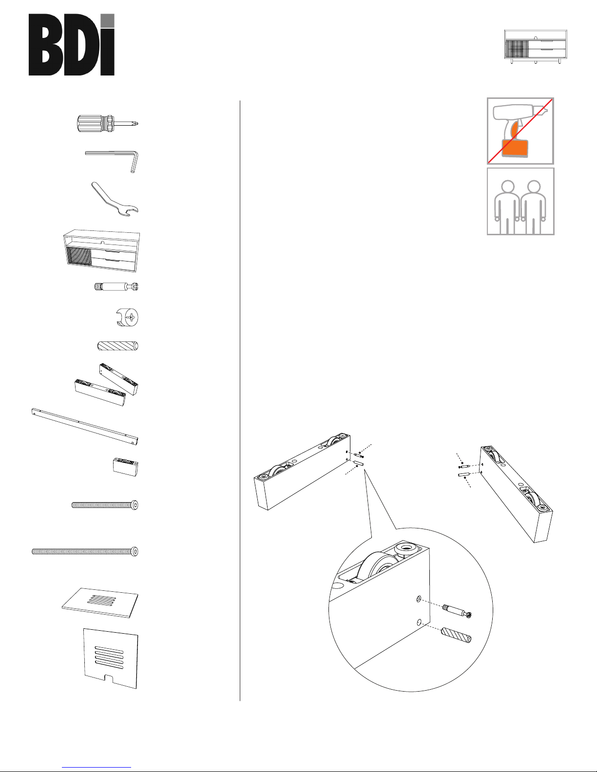
Unpack and Identify
Unpack and identify the components at left. Note
that some components are shipped inside the
cabinet. The assembly workspace should be a nonmarring surface such as carpet. For missing hardware pieces, please
contact BDI Customer Service at customerservice@bdiusa.com. For all
other concerns, please contact your BDI Retailer.
Component List
Designed by Matthew Weatherly.
These distinctive product congurations are protected by US and international patents,
trade dress, and/or copyright laws.
BDI are trademarks of Becker Designed, Inc.
All Rights reserved. ©2014, BDI
Made in China. 8556REV100815v3
Step 2
Install and tighten Cam Bolts (D) into Side Legs (G) using Phillips
Screwdriver (A). Insert Wood Dowels (F) into corresponding holes of
Side Legs (G).
B2 - Leveler Wrench
x 1
A - Phillips Screwdriver
x 1
B1 - Hex Wrench
x 1
C - Cabinet x 1
F - Wood Dowel x 2
E - Cam Fitting x 2
D - Cam Bolt x 2
H - Base Stretcher
x 1
I - Center Leg x 1
G - Side Legs x 2
L - Adjustable Shelf
x 1
M - Back Panel
x 1
K - 1/4-20 x 100 mm
Machine Screw
x 6
J - 1/4-20 x 60 mm
Machine Screw
x 3
F
D
G
F
F
D
D
G
G
vertica
8556
home theater
assembly instructions
bdiusa.com customerservice@bdiusa.com
TWO PERSON ASSEMBLY
Page 2
2
assembly instructions
bdi
usa.com customerservice@bdiusa.com
vertica
85 56 ho me t he ate r
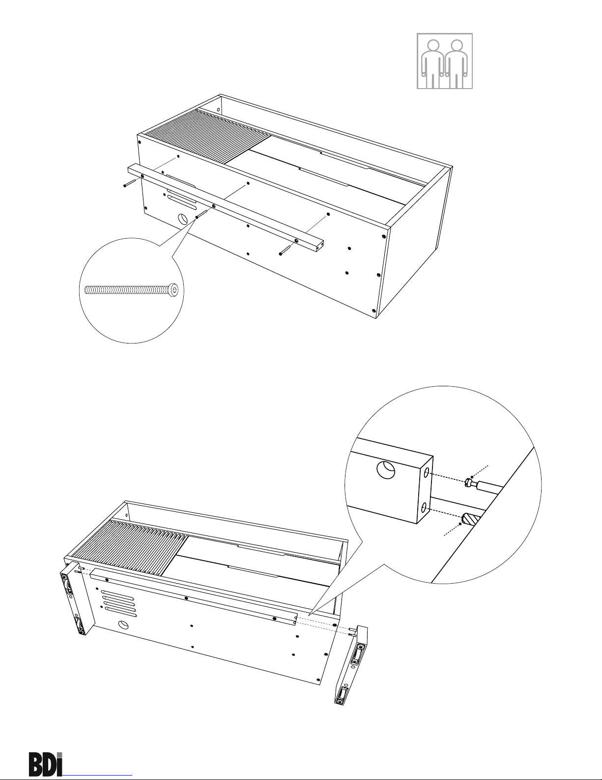
Step 4
Align Cam Bolt (D) and Wood Dowel (F) of Side Legs (G) into their
respective holes in Base Stretcher (H).
Step 3
Carefully lay Cabinet (C) on its back. Attach Base Stretcher (H) to bottom of
Cabinet (C) using Screw (J). Only hand tighten screws at this point.
J
J
J
H
C
J x 3
G
G
H
TWO PERSON ASSEMBLY
H
D
F
G
Page 3
3
assembly instructions
bdi
usa.com customerservice@bdiusa.com
vertica
85 56 ho me t he ate r
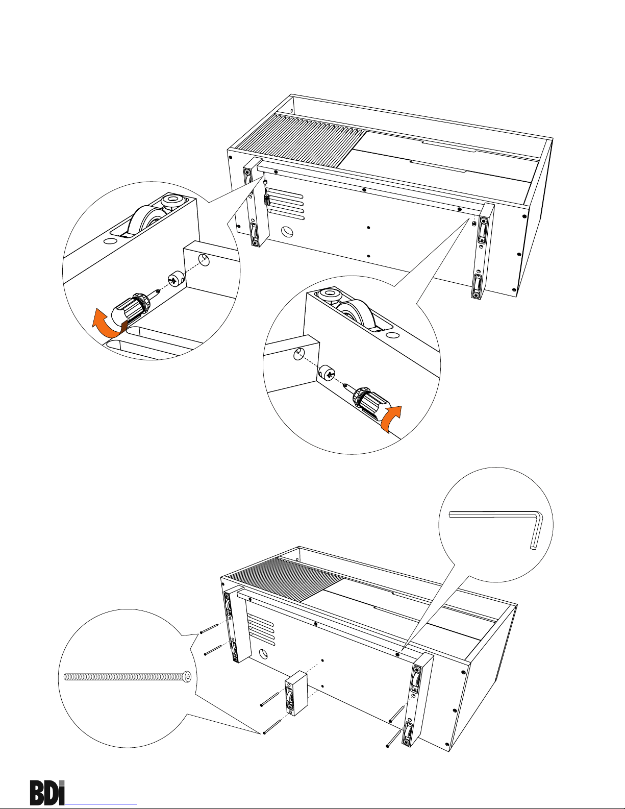
Step 6
Using Hex Wrench (B1) attach Side Legs (G) and Center Leg (I) to bottom
of Cabinet (C) with Screws (K). Fully tighten Base Stretcher (H) screws that
were left loose in Step 3 using Hex Wrench (B1).
Step 5
Insert Cam Fittings (E) into holes of Base Stretcher (H) with the arrow of the
Cam Fitting (E) pointing outward on each end of the Stretcher. Tighten each
Cam Fitting (E) clockwise using Phillips Screwdriver (A) until it no longer
rotates.
K
K
K
I
G
G
K
K
K
K x 6
E
E
H
A
E
H
A
E
H
A
B1
H
Page 4

4
assembly instructions
bdi
usa.com customerservice@bdiusa.com
vertica
85 56 ho me t he ate r
Step 7
Position Cabinet right side up while carefully supporting drawer fronts to prevent
drawers from sliding open. Install Back Panel (M) to the backside of the
Cabinet (C) by inserting top edge in upper channel then tipping bottom edge
forward and into lower channel.
2
C
M
1
The shelf pins located inside the
outer cabinet spaces may be
repositioned, allowing you to raise
and lower the Adjustable Shelf (L)
to the desired level.
TWO PERSON ASSEMBLY
Page 5

5
assembly instructions
bdi
usa.com customerservice@bdiusa.com
vertica
85 56 ho me t he ate r
Step 8
Drawer Position Options
Two (2) adjustment mechanisms are found on
underside of each Vertica drawer, at left and
at right. All drawer position adjustments
require removal of indicated screw on both
adjustment mechanisms. Save screws for
re-installation prior to any future cabinet shipment.
OUT
DOWN
IN
UP
Front-to-Back Adjustment: Turn Black Wheel on one
or both mechanisms, as necessary, to adjust drawer
position in or out.
Lateral Adjustment: Turn White Wheel on both
mechanisms to adjust drawer position left or right.
Vertical Adjustment: Manipulate Orange Lever on one
or both mechanisms, as necessary, to adjust drawer
position up or down.
Page 6

6
assembly instructions
bdi
usa.com customerservice@bdiusa.com
vertica
85 56 ho me t he ate r
Fine tuning your new BDI Vertica Home Theater Furniture
These steps are to be followed after you have unpacked and completed the simple assembly instructions for your
Vertica AV cabinet. Due to jostling in freight or perhaps an uneven oor, the door on your Vertica cabinet may
not appear to be in perfect alignment. Making a few minor adjustments can rectify this situation. Be aware that
depending on your situation, patience and a bit of trial and error are required.
STEP 1 - Level your Vertica unit
Levelers are integrated into each leg assembly and are accessed at the bottom of each cabinet leg using Leveler
Wrench (B2). If your oor is uneven, you may extend one or more levelers to attain a level, stable cabinet
placement. Turning the leveler clockwise will extend the leveler; turning it counter-clockwise will retract it.
Optional Flat Panel TV Mount
This BDI cabinet is compatible with BDI’s Arena Flat-Panel TV
Mount #9972 (sold separately), with the following features:
• accommodates most TVs up to 70", 175 lbs
• swivel allows rotating for optimal viewing
• allows adjustable TV mounting height
• accepts and routes cables to and from the TV
For more information, visit www.bdiusa.com
Step 8b
Drawer Removal: Depress Orange Release Lever on both mechanisms
simultaneously, then carefully lift drawer up and away from cabinet.
Page 7

7
assembly instructions
bdi
usa.com customerservice@bdiusa.com
vertica
85 56 ho me t he ate r
CORRECT! Door is
sitting squarely and evenly
spaced on tops and sides.
INCORRECT! Door is
out of alignment with
the rest of the unit.
STEP 2 - Adjust Door Hinges (if needed)
The door on your cabinet should be evenly spaced and should open/close freely without rubbing against the door
frame.
If the doors appear out of alignment, this condition can be corrected with minor adjustment to the European hinges
on each door.
Because these hinges are innitely adjustable, adjusting one hinge element can sometimes cause the need for
adjustments to other elements. But with a few adjustments, you can modify the orientation of the door to make
sure that it is aligned within your cabinet.
Use the Push Rebound Mechanism (3) :
• By adjusting the dial Clockwise, the door will move IN
when closed.
• By adjusting the dial Counter Clockwise, the door will
move OUT when closed.
Use the supplied Phillips Screwdriver (A) to adjust Vertica's door
hinges:
• By adjusting Screw 1, the door will move LEFT or
RIGHT within the frame. Make minor adjustments
at both top and bottom hinges for best results.
• By adjusting Screw 2 the entire door will move IN or
OUT, opening or closing the gap between the door frame
and cabinet. (This screw rarely needs adjustment.)
1.
2.
2.
1.
In
Out
3.
 Loading...