

Page 1
signal
8323 AND 8329
cabinet
assembly instructions
bdiusa.com customerservice@bdiusa.com
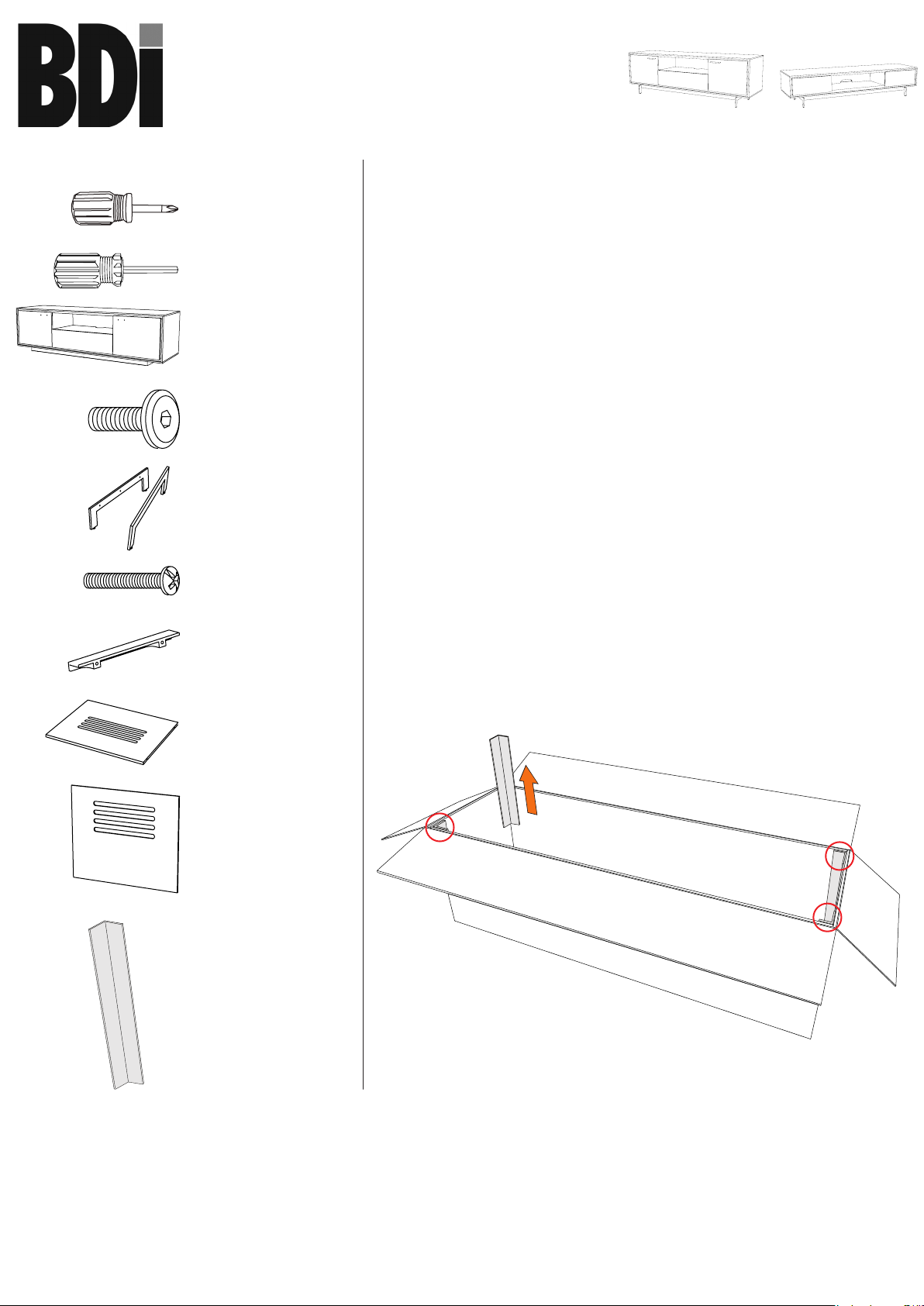
Component List
A - Phillips Screwdriver
x 1
B - Hex Driver
x 1
C - Assembled Cabinet
x 1
D - 1/4-20 x 1"
Machine Screw
x 6
E - Leg
x 2
F - M4 x 25mm Screw
x 4
Signal is engineered for easy assembly. Carefully follow this
procedure to prevent any damage.
Don't discard packaging until reading these instructions.
NOTE: This instruction sheet is intended for the entire Signal
collection; model 8329 is shown for illustration.
Placement and Maintenance
Signal is designed for indoor use on level floors. Clean steel parts
and wood veneer with a moist cloth. Many wood surfaces are
subject to fading under direct sunlight. BDI’s unique Graphite finish
has properties that make it more sensitive than others. Please avoid
placing BDI’s Graphite finish in direct sunlight.
Step 1
Unpack and Identify
Unpack and identify the components at left. Note that some
components are shipped inside the cabinet. The assembly
workspace should be a non-marring surface such as carpet. For
missing hardware pieces, please contact BDI Customer Service
at customerservice@bdiusa.com. For all other concerns, please
contact your BDI Retailer.
G - Pull
x 2
Step 2
Remove Cardboard Corner Protectors (J) from packaging.
H - Adjustable Shelf
x 2
I - Back Panel x 2
J - Cardboard Corner
Protector
x 2
J
Designed by Noah Packard.
These distinctive product congurations are protected by US and
international patents, trade dress, and/or copyright laws.
BDI are trademarks of Becker Designed, Inc.
All Rights reserved. ©2012, BDI
Made in China. 8323_8329REV112114v4
1
Page 2
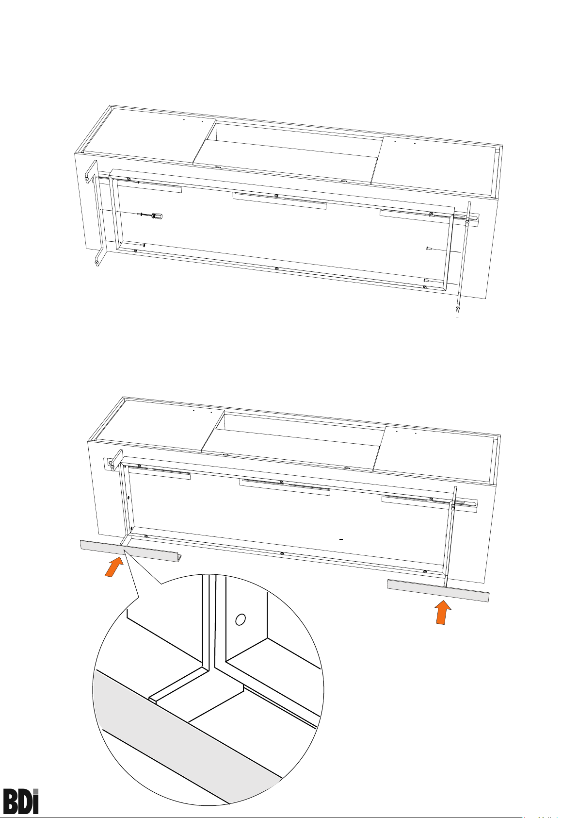
Step 3
Install Legs
With Assembled Cabinet (C) resting safely on its back side, install Legs (E)
to cabinet bottom using 1/4-20 x 1" Machine Screw (D) and tighten with
Hex Driver (B). Do not overtighten.
D
D
D
E
CAUTION: FOLLOW THIS STEP CAREFULLY TO AVOID DAMAGE TO
YOUR FLOOR.
Step 4
Position cabinet right side up.
Place the Cardboard Corner Protectors (J) from packaging underneath
the installed cabinet Legs (E). With the help of another person, carefully tip
cabinet upright onto cabinet Legs (E). Slide Cardboard Corner Protectors
(J) from underneath cabinet Legs (E).
D
D
D
E
Cardboard Corner Protector (J)
signal
83 23 an d 83 29 ca bi ne t
J
Leg (E)
J
2
assembly instructions
bdiusa.com customerservice@bdiusa.com
Page 3

Step 5
Install Pulls
Install Pulls (G) on the doors using the M4 x 25mm Screws (F) and the
Phillips Screwdriver (A) supplied.
G
F
Step 6
Install Back Panels
Install both Back Panels (I) to the backside of the cabinet by inserting top
edge in upper channel, then tipping bottom edge forward and into lower
channel.
NOTE: Velcro straps are included as wire management for your
convenience.
2
1
Optional Flat Panel TV Mount
The shelf pins located inside
the left and right cabinet space
may be repositioned, allowing
you to raise or lower each shelf
to the desired level.
These BDI cabinets are compatible with BDI’s Arena Flat-Panel TV
Mount #9972 (sold separately), with the following features:
• accommodates most TVs up to 60”, 175 lbs
• swivel allows rotating for optimal viewing
• allows adjustable TV mounting height
• accepts and routes cables to and from the TV
•
For more information, visit www.bdiusa.com
signal
83 23 an d 83 29 ca bi ne t
Signal 8329 is also compatible with BDI’s Arena Flat-Panel TV
Mount #9970 (sold separately).
3
assembly instructions
bdiusa.com customerservice@bdiusa.com
Page 4

Fine tuning your new BDI Signal Home Theater Furniture
These steps are to be followed after you have unpackaged and completed the simple assembly instructions for
your Signal AV stand. Due to jostling in freight or perhaps an uneven floor, the doors on your Signal stand may
not appear to be in perfect alignment. Making a few minor adjustments can rectify this situation. Be aware that
depending on your situation, patience and a bit of trial and error are required. The high-quality European hinge
hardware is infinitely adjustable, but changing one element can cause the need for further adjustments. Through a
little adjustment, you can modify the orientation of the cabinet doors to make sure that they are sitting perfectly on
your Signal unit.
STEP 1 - Level your Signal unit
Levelers are integrated into each leg assembly and are accessed at the bottom of each cabinet leg and are handadjustable. If your floor is uneven, you may extend one or more levelers to attain a level, stable cabinet placement.
Turning the leveler clockwise will extend the leveler; turning it counter-clockwise will retract it.
INCORRECT! Door is
out of alignment with
the rest of the unit.
STEP 2 - Adjust Door Hinges (if needed)
The doors on your cabinet should be evenly spaced and the doors should open and close freely without rubbing
against the door frame.
If the cabinet’s doors appear out of alignment, this condition can be corrected with minor adjustment to the
European hinges on each door.
Because these hinges are infinitely adjustable, adjusting one hinge element can sometimes cause the need for
adjustments to other elements. But with a few adjustments, you can modify the orientation of the cabinet doors
to make sure that they hang perfectly within your cabinet.
Use the Phillips Screwdriver (A) supplied to adjust Signal's
door hinges:
CORRECT! Door is
sitting squarely and
evenly spaced on tops
and sides.
• By adjusting Screw 1, the door will move LEFT or
RIGHT within the frame. Make minor adjustments
at both top and bottom hinges for best results.
• By adjusting Screw 2 the entire door will move IN or
2.
OUT, opening or closing the gap between the door
frame and cabinet. (This screw rarely needs adjustment.)
2.
1.
signal
83 23 an d 83 29 ca bi ne t
1.
4
assembly instructions
bdiusa.com customerservice@bdiusa.com
 Loading...