

Page 1

CENTRO
LIFT DESK
INSTRUCTION MANUAL
™
6451-2/6452-2
LET’S GET STARTED.
DESIGN MATTHEW WEATHERLY
6451-2 SHOWN
Page 2

Page 3

Congratulations on the purchase of your Centro Lift Desk 6451-2 / 6452-2 from BDI. Your
desk has been designed to provide a lifetime of enjoyment. This manual will provide you
with assembly instructions and other helpful information that will ensure that you get
the most out of your desk. Please save it for future reference.
Your Centro Lift Desk is designed for indoor use on level floors. It has been engineered
for easy assembly. Please follow these directions carefully to prevent any damage.
Should you need further assistance, contact BDI at customerservice@bdiusa.com.
ENJOY!
BDIUSA.COM | 3NEED ASSISTANCE? customerservice@bdiusa.com
Page 4

HARDWARE AND COMPONENTSHARDWARE AND COMPONENTS
Unpack and identify the parts listed below. The assembly workspace should be a non-marring
surface such as carpet. For missing hardware pieces, please contact BDI Customer Service at
customerservice@bdiusa.com.
Do not use power tools for assembly of this product.
For all other concerns, please contact your BDI retailer.
PART #
DESCRIPTION
QUANTITY
PART #
DESCRIPTION
QUANTITY
PART #
DESCRIPTION
QUANTITY
T1
4mm Hex Wrench
1
H3
Cord Wrap
2
H6
M6 x 12mm
Screw
5
DESCRIPTION
DESCRIPTION
PART #
DESCRIPTION
QUANTITY
PART #
QUANTITY
PART #
QUANTITY
H7
Cord Clip
6
H1
Long Wood Screw
2
H4
M6 x 16mm Screw
8
PART #
DESCRIPTION
QUANTITY
DESCRIPTION
DESCRIPTION
H8
Glass
Bumper
2
PART #
QUANTITY
PART #
QUANTITY
DESCRIPTION
Short Wood Screw
M6 x 15mm Screw
PART #
QUANTITY
H2
12
H5
10
H9
Dual Lock
Dot
8
PART #
DESCRIPTION
QUANTITY
4 | BDIUSA.COM CENTRO 6451-2 & 6452-2
A1
Main Panel
1
Page 5

HARDWARE AND COMPONENTS
PART #
DESCRIPTION
QUANTITY
PART #
DESCRIPTION
QUANTITY
PART #
DESCRIPTION
C1
Keypad
1
C4
Cord Extension
1
C7
Wire Tray
PART #
DESCRIPTION
QUANTITY
PART #
DESCRIPTION
QUANTITY
C2
Control Module
1
C5
Foot
2
PART #
DESCRIPTION
PART #
DESCRIPTION
QUANTITY
PART #
DESCRIPTION
QUANTITY
Cord Conduit
C3
Leg
2
C6
Power Cord
1
C8
QUANTITY
PART #
DESCRIPTION
QUANTITY
1
C9
Glass Panel
1
QUANTITY
1
PART #
DESCRIPTION
QUANTITY
TOOL REQUIRED (NOT INCLUDED)
Phillips Screwdriver
BDIUSA.COM | 5NEED ASSISTANCE? customerservice@bdiusa.com
C10
Grommet Cover
1
Page 6

STEP 1. INSTALL CONTROL MODULE AND KEYPADASSEMBLY
Lay (A1) Main Panel upside down on a soft
surface (carpet). Attach (C1) Keypad on the
desired side (choose left or right) with 2 (H2)
Short Wood Screws and a Phillips Screwdriver.
IMPORTANT! Orient the (C2) Control Module
so that the keypad cord socket (labeled HS) is
facing the keypad side and secure between the
2 steel rails with 2 (H1) Long Wood Screws as
shown. Route the keypad cord into the groove
in the panel and through the hole in the metal
frame. Attach 2 (H3) Cord Wraps (Kleet) using
(H2) Short Wood Screws.
Left hand
side
C1 C1
Choose
PART/DESCRIPTION QTY
H1-WOOD SCREW 2
H2-WOOD SCREW 6
H3-CORD WRAP 2
NOT INCLUDED
Phillips Screwdriver
Right hand
side
Route cord
through hole in
metal frame
1
H1
H1
C2
H2
A1
H2
Groove for
H3
6 | BDIUSA.COM CENTRO 6451-2 & 6452-2
keypad cord
C1
Page 7

STEP 2. CONNECT & SECURE KEYPAD
ASSEMBLY
Attach keypad cord into the (C2) Control
Module socket (labeled HS) and bundle the
slack with the hook and loop tie. Secure the
keypad cord into the groove using 6 (H7) Cord
Clips and 6 (H2) Short Wood Screw. Tighten
with a Phillips Screwdriver.
C2
loop tie
Hook &
PART/DESCRIPTION QTY
H2-WOOD SCREW 6
H7-CORD CLIP 6
NOT INCLUDED
Phillips Screwdriver
H2
H2
1
H7H7
H2
H7
H2
H7
Keypad cord
inside groove
H2
H7
H2
H7
H2
H7
BDIUSA.COM | 7NEED ASSISTANCE? customerservice@bdiusa.com
Page 8

STEP 3. INSTALL LEGSASSEMBLY
Attach 2 (C3) Legs with 4 (H5) Screws per leg
using (T1) Hex Wrench. Start all 4 screws before
tightening them down. Connect (C4) Cord
Extension into the top of (C2) Control Module.
Connect 1 leg cord to the end of (C4) Cord
Extension, connect the other leg cord to the
other end of the (C2) Control Module and bundle
up any slack using the hook and loop ties.
C4
C3
C4
PART/DESCRIPTION QTY
T1-HEX WRENCH 1
H5-SCREW 8
C2
C2
H5
H5
H5
H5
C3
H5
H5
C4
C3
C2
H5
H5
8 | BDIUSA.COM CENTRO 6451-2 & 6452-2
Page 9

STEP 4. INSTALL FEET
ASSEMBLY
Attach (C5) Feet with (H4) Flathead Screws
and (T1) Hex Wrench. Make sure the longer end
of the feet are facing the front of the desk
(same side as keypad).
H4
C5
H4
Long end this side
C5
PART/DESCRIPTION QTY
T1-HEX WRENCH 1
H4-SCREW 8
H4
C5
BDIUSA.COM | 9NEED ASSISTANCE? customerservice@bdiusa.com
Page 10

STEP 5. INSTALL WIRE TRAY—OPTIONALASSEMBLY
Determine if you prefer the wire tray to be
centered, shifted left or shifted right. If you plan
to use a monitor arm, it might be better to shift
the position of the (C7) Wire Tray to make the
monitor arm attach more centrally. Attach the
metal (C7) Wire Tray to the back edge of the
bottom of the desk with 2 (H5) Screws.
Shifted Right Shifted Left
PART/DESCRIPTION QTY
H5-SCREW 2
C7
H5
H5
10 | BDIUSA.COM CENTRO 6451-2 & 6452-2
Page 11

STEP 6. ATTACH SURGE PROTECTOR—NOT INCLUDED
Secure 4 pairs of (H9) Dual-Lock Dots to the
bottom corners of your surge protector.
Surge Protector (not included)
ASSEMBLY
PART/DESCRIPTION QTY
H9-DUAL LOCK DOT 4
Attach Dual Lock
together
ATTACH YOUR SURGE PROTECTOR—NOT INCLUDED
Determine where you prefer your surge protector to be mounted. We suggest just behind the metal
rails towards the leg closest to your wall outlet. Make sure the area is dust free. Remove the
adhesive film and attach the surge protector with the power cord facing the nearest leg. Press
firmly to allow the pressure sensitive adhesive to set.
Surge Protector
(not included)
BDIUSA.COM | 11NEED ASSISTANCE? customerservice@bdiusa.com
Page 12

ASSEMBLY
Attach the (6459-2) Optional Drawer (for 6451-2/6452-2) using 4 Screws that came with your
drawer as shown.
STEP 7. INSTALL DRAWER—OPTIONAL
6459-2
ASSEMBLY
Plug the (C6) Power Cord into the power port on the (C2) Control Module (labeled AC).
12 | BDIUSA.COM CENTRO 6451-2 & 6452-2
STEP 8. PLUG POWER CORD
C2
C6
Page 13

2 PERSON TASK
STEP 9. ATTACH DUAL LOCK FASTENER—OPTIONAL
With the help of another person, carefully pick up, rotate, and place the desk on to its feet. Plug the
other end of the Power Cord into the nearest wall socket. Refer to the User Manual on Page 18 and
follow the Reset Procedure. You may now adjust the height of your desk to make the remaining
steps easier.
ASSEMBLY
STEP 10. INSTALL GLASS BUMPERS
Install the 2 (H8) Glass Bumpers as shown.
H8
ASSEMBLY
PART/DESCRIPTION QTY
H8-GLASS BUMPER 2
H8
BDIUSA.COM | 13NEED ASSISTANCE? customerservice@bdiusa.com
Page 14
2 PERSON TASK
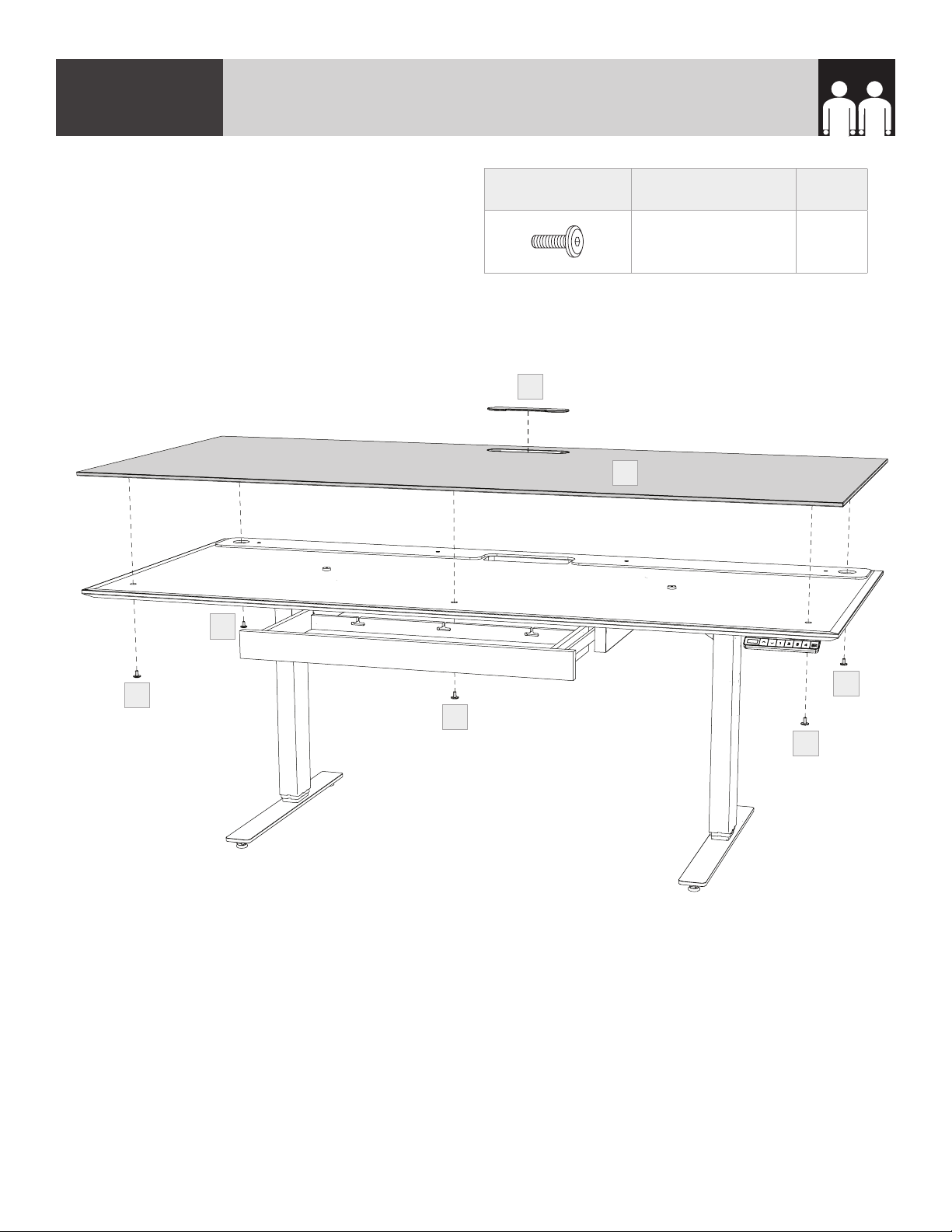
STEP 11. INSTALL GLASS PANEL & GROMMET COVERASSEMBLY
With the help of another person, carefully place
the (C8) Glass Panel on top of the desk top with
the metal pucks facing down. The stem of the
glass pucks should slip into 5 holes. Secure the
(C8) Glass Panel in place from below using
5 (H6) Screws. Do not over tighten. Open
drawer to attach front, center screw. Place
(C9) Grommet Cover into the grommet hole.
PART/DESCRIPTION QTY
H6-SCREW 5
C9
C8
H6
H6
H6
H6
H6
14 | BDIUSA.COM CENTRO 6451-2 & 6452-2
Page 15

STEP 12. ATTACH CORD CONDUIT—OPTIONAL
Remove adhesive film and attach the (C6) Cord Conduit to the back of the top section of the leg
nearest the wall outlet. Insert power cord(s) into (C6) Cord Conduit.
C6
ASSEMBLY
C6
C6
BDIUSA.COM | 15NEED ASSISTANCE? customerservice@bdiusa.com
Page 16

STEP 13. INSTALL MONITOR ARM—OPTIONAL, NOT INCLUDEDASSEMBLY
The Centro Lift Desk is compatible with most third party monitor arms. Attach your monitor arm on
either side of the grommet hole along the back edge, staying at least 1" away from the grommet
hole. The Centro Lift Desk can support 75lb (34Kg) on a monitor arm.
Optional Monitor Arm
(not included)
16 | BDIUSA.COM CENTRO 6451-2 & 6452-2
Page 17

WIPE EXCESS LEG LUBRICANT
When new, the legs may have excess lubricant. Extend the legs to their highest position and wipe
off excess lubricant with a clean, dry cloth or rag.
FINE TUNING
BDIUSA.COM | 17NEED ASSISTANCE? customerservice@bdiusa.com
Page 18

USER MANUAL
CAUTION!
nMake sure there are no obstacles under or over the path of the desk.
nMake sure the desk top is not touching any walls.
nMake sure all the cords are long enough to reach lowest and highest desk positions.
!!
!!
IMPORTANT: YOU MUST RESET THE DESK PRIOR TO USE.
RESET PROCEDURE
1. Press and hold the DOWN button on the keypad until the desk reaches its lowest height.
2. Release the DOWN button.
3. Press and hold the DOWN button again until the LED display reads “RST”.
4. Release the DOWN button.
5. Press and hold the DOWN button again until the desk lowers a little bit more, slightly rises and
stops.
6. Release the DOWN button. Your desk is now ready for use.
“Reset”
looks like this
Up Down Memory
18 | BDIUSA.COM CENTRO 6451-2 & 6452-2
Page 19

HEIGHT ADJUSTMENT
The desk base can be adjusted by pressing and holding either the UP or DOWN button until the
desired height is reached.
To program up to four presets, use the up/down buttons to find a desired height, then press “BDI”
followed by a number 1-4. To Change the Movement Program (explained below) follow the Reset
Procedure to Step 4. The display should be flashing “RST”. Press and hold the “1” button (about 5
seconds) until the display flashes “10.1” or “10.2”. You can press and hold the “1” button again to
switch to the other setting. Once the chosen setting is selected finish the Reset Procedure steps 5
and 6.
ONE TOUCH (DEFAULT)—10.1
Once a preset button is pushed, the desk will move to the programmed height. To stop movement,
press any number on the keypad.
CONSTANT TOUCH—10.2
A preset button must remain pressed for the desk to move to the programmed height. To stop
movement, release the button.
TROUBLE SHOOTING
If your desk is not functioning properly it may need to be reset. Follow the RESET procedure on
page 18. If your LED readout displays an error message Er1 confirm that all wired connections are
secure. Then perform the reset procedure above.
KEYPAD LOCK
To lock the keypad:
Press and hold the “BDI” button for about 8 seconds until the LED display reads “LOC”. The keypad
is now locked and cannot be used to move the desk.
To unlock the keypad:
Press and hold the “BDI” button for about 8 seconds until the LED display switches from “LOC” to
the height display. The keypad is now unlocked and can be used as normal.
HEIGHT DISPLAY: INCHES OR CENTIMETERS
To change unit of height measurements (inches or centimeters) follow the Reset Procedure to Step 4.
The display should be flashing “RST”. Press and hold the “2” button (about 5 seconds) until the
display flashes “10.3” or “10.4”. You can press and hold the “2” button again to switch to the other
setting. Once the chosen setting is selected, finish the Reset Procedure steps 5 and 6.
Centimeters—10.3
Inches (Default)—10.4
BDIUSA.COM | 19NEED ASSISTANCE? customerservice@bdiusa.com
Page 20

SETTING THE UPPER AND LOWER LIMITS
The base is designed to go to its minimum and maximum heights, allowing for the widest possible
range. If you prefer to change the settings to a more narrow range, follow these steps:
TO SET THE LOWER-LIMIT POSITION
Use the UP/DOWN buttons to move the base to the desired minimum height position. Press and
release the “BDI” button and the LED display should read “S”. Next, press and release the DOWN
button. Now, press and hold the “BDI” button (for about 2 seconds) until the LED display changes to
“000” and then automatically returns to show the selected height. The new lower limit is now set.
TO SET THE UPPER-LIMIT POSITION
Use the UP/DOWN buttons to move the base to the desired maximum height position. Press and
release the “BDI” button and the LED display should read “S”. Next, press and release the UP button.
Now, press and hold the “BDI” button (for about 2 seconds) until the LED display changes to 999 and
then automatically returns to show the selected height. The new upper limit is now set.
NOTE
nYou can set just the upper limit or just the lower limit or both.
nAfter the upper and lower limits are set, the previous memory positions (1,2,3,4) may be outside
the new range of movement. If so, simply reset the memory positions.
nIf you attempt to revise a previously set upper or lower limit and it is outside of the existing
range, you will need to remove the previously set upper/lower limits first.
A Reset Procedure requires the desk to be fully lowered (beyond any lower limit set). Please ensure
that you have the proper clearance below the desk!
TO REMOVE THE UPPER/LOWER LIMIT POSITIONS
Press and release the “BDI” button and the LED display should read “S”. Within 5 seconds, press and
hold the “BDI” button until the display flashes “555”. The upper and lower limits are now removed.
TECHNICAL SPECIFICATIONS
Height Range 24.75"–49.75" (63–126 cm)
Travel Speed 1.5" per second
Weight Capacity 150 lbs (68 kg)
Duty Cycle 10%, Max 2 minutes with 18 minutes off
Memory 4 position presets
Monitor Arm Compatible Yes
20 | BDIUSA.COM CENTRO 6451-2 & 6452-2
Page 21

TROUBLE SHOOTING
If your desk is not functioning properly it may need to be reset. Follow the RESET procedure above.
If your LED readout displays an error message Er1 confirm that all wired connections are secure.
Then perform the reset procedure above.
Check that all
cables and the
power cord are
correctly plugged
in. Is the desk now
working properly?
YES
NO
Does the display
read “HO1”?
YES YES
Let the leg motors
cool down for up to
20 minutes
You’re
Done!
NO
YES
Does the display
read “RST”?
Follow the system
reset procedure.
Is the desk now
working properly?
NO
NO
NO
Does the display
NO
read “E01”–“E08”
or is one of the legs
Disconnect and
reconnect the
leg cords to the
control module and
perform a reset. Is
there still an error
code or a leg still
Swap the cables in
the control module
ports M1 and M2.
Perform a system
reset. Is the same
leg still lagging or is
the same error code
number shown?
lagging?
YES
lagging?
YES
NO
Contact BDI
Customer Service
to replace the
control module
YES
Contact BDI
Customer Service
to replace the leg
that is lagging
Contact
BDI
Customer
Service
BDIUSA.COM | 21NEED ASSISTANCE? customerservice@bdiusa.com
Page 22

CARE & MAINTENANCE
GLASS
Glass surface is maintained using household glass cleaner and a paper towel or cloth.
SATIN-ETCHED GLASS
This uniquely smooth-to-the-touch glass surface can be regularly maintained using household glass
cleaner and a paper towel or cloth. Minor scratches or scuffs not eliminated using paper towel or cloth
can usually be removed by using a ‘Magic Eraser’. Magic Eraser is a melamine foam product available
at any grocery store or home improvement center. Dampen the entire glass surface as well as the
Magic Eraser, then rub the entire glass surface in broad, even strokes using moderate pressure. Clean
and dry the surface with a paper towel. Check for results and repeat as necessary.
Any scratches or scuffing not eliminated by one of the above methods can often be addressed by
‘refreshing’ the glass. This is a process that should not be required more than once per 6-12 months.
See this brief video for the simple method: www.bdiusa.com/glass
WOOD
Wood surfaces should be cleaned with a slightly damp (not saturated) cloth or paper towel. Do not
use glass cleaner on wood. If moisture remains, dry the surface with another cloth. If needed, a gentle
non-abrasive cleanser may be used, but be sure to wipe away all cleaner residue and dry the surface
with a cloth.
BDI’s wood finishes feature natural hardwood solids and veneers. Wood is a product of nature and—
unlike man-made materials that can be manufactured to strict and consistent specifications—has
natural imperfections that are part of its appeal and character. Every piece of wood differs from every
other, even when coming from the very same tree. As such, variation in grain, texture and tone should
be expected from one panel or piece of furniture to the next.
While BDI’s stained wood finishes are stable in tone & appearance, all finishes are subject to some
degree of discoloration with prolonged exposure to direct sunlight. Please take care to avoid
positioning your BDI cabinet in any area with extensive direct sunlight. To learn more about the
features of natural wood, visit www.bdiusa.com/wood
METAL & PAINTED SURFACES
Surfaces should be cleaned with a slightly damp (not saturated) cloth or paper towel. If moisture
remains, dry the surface with another cloth. If needed, a gentle non-abrasive cleanser may be used,
but be sure to wipe away all cleaner residue and dry the surface with a cloth.
22 | BDIUSA.COM CENTRO 6451-2 & 6452-2
Page 23

WARRANTY
BDI warrants to the original purchaser that for the below stated warranty term, BDI will repair or
replace any product, part, or component covered by this warranty which fails under normal use as a
result of a defect in material or workmanship. BDI will repair or replace the aforementioned product,
part or component with a comparable product, part or component. The decision to repair or replace
will be at BDI’s sole discretion.
BDI Home Theater Furniture, Office Furniture, Modular Systems, Tables and other furniture pieces
are warranted for three (3) years from the date of purchase as shown on your sales receipt. The
warranty period starts from the date of purchase. This warranty extends only to the original
purchasers who acquire new product from BDI Authorized Resellers. Any product, part, or
component must have been assembled, installed, used, and maintained according to BDI’s published
instructions in order to be eligible for warranty coverage. Any modification to the original product
voids the warranty.
To view BDI’s complete warranty information, visit www.bdiusa.com/warranty
PRODUCT REGISTRATION
Registering your new BDI product allows us to send you important product updates, service
information and helpful hints related to your BDI products. Register today, and you will be entered
to win free a BINK table from BDI: www.bdiusa.com/register
WARNING
SERIOUS OR FATAL CRUSHING INJURIES CAN OCCUR FROM FURNITURE TIP-OVER. TO HELP
PREVENT TIP-OVER:
nInstall tip-over restraint.
n Place heaviest items in lower compartments.
nNever allow children to climb or hang on drawers, doors or shelves.
nNever open more than one drawer at a time.
USE OF TIP-OVER RESTRAINT MAY REDUCE—BUT NOT ELIMINATE—THE RISK OF TIP-OVER.
BDIUSA.COM | 23NEED ASSISTANCE? customerservice@bdiusa.com
Page 24

These distinctive product configurations are protected by US and international patents, trade
dress, and/or copyright laws. Centro & BDI are trademarks of Becker Designed, Inc. All rights
reserved. ©2020, BDI | V.05.28.2020
Made in Vietnam.
 Loading...