

Page 1

ATTENTION:
PLEASE FOLLOW
THESE INSTRUCTIONS
CAREFULLY.
®
SEQUEL
Sequel Corner 6019
Assembly and Placement Information
OFFICE
BDIUSA.COM
CORNER
6019
Page 2

desk and return
2
Page 3
features
Thanks for purchasing the
Sequel System.
Before you begin setting up the Sequel System Components,
it is imperative that you read the Consumer Considerations
section on the next page.
3
Page 4
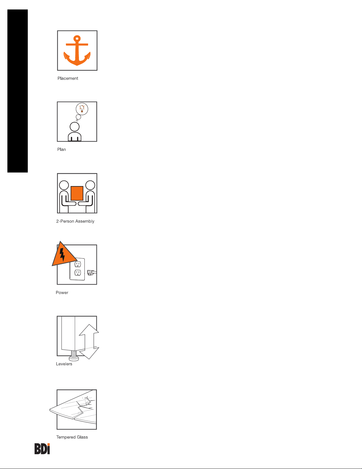
Placement
Once the Sequel System is fully assembled, it cannot be moved.
Make all positioning adjustments prior to final assembly.
Plan your space.
Forethought is essential in determining the placement of each
component. Using a measuring tape, determine how much
fl oor space each unit will require. A cardboard template has
been provided in order to help aid this process.
Consumer Considerations
Get someone to help you.
Help from a second person is required for the majority of the
steps outlined in this instruction manual.
AC power outlet and wire management
Depending on the configuration of your office set up, the Sequel
cabinet may end up resting in front of an AC power outlet. If
so, be sure to plug in the AC power strip, phone/ethernet or
extension cords prior to placing the cabinet in its final position.
Leveling
SEQUEL Furniture is designed for indoor use on level floors. If
the floors are uneven, adjust levelers as necessary.
Tempered glass.
Exercise caution while handling the glass, and be sure to
employ the help of another person. Keep edges of glass panels
away from hard surfaces in order to prevent breakage.
4
Page 5
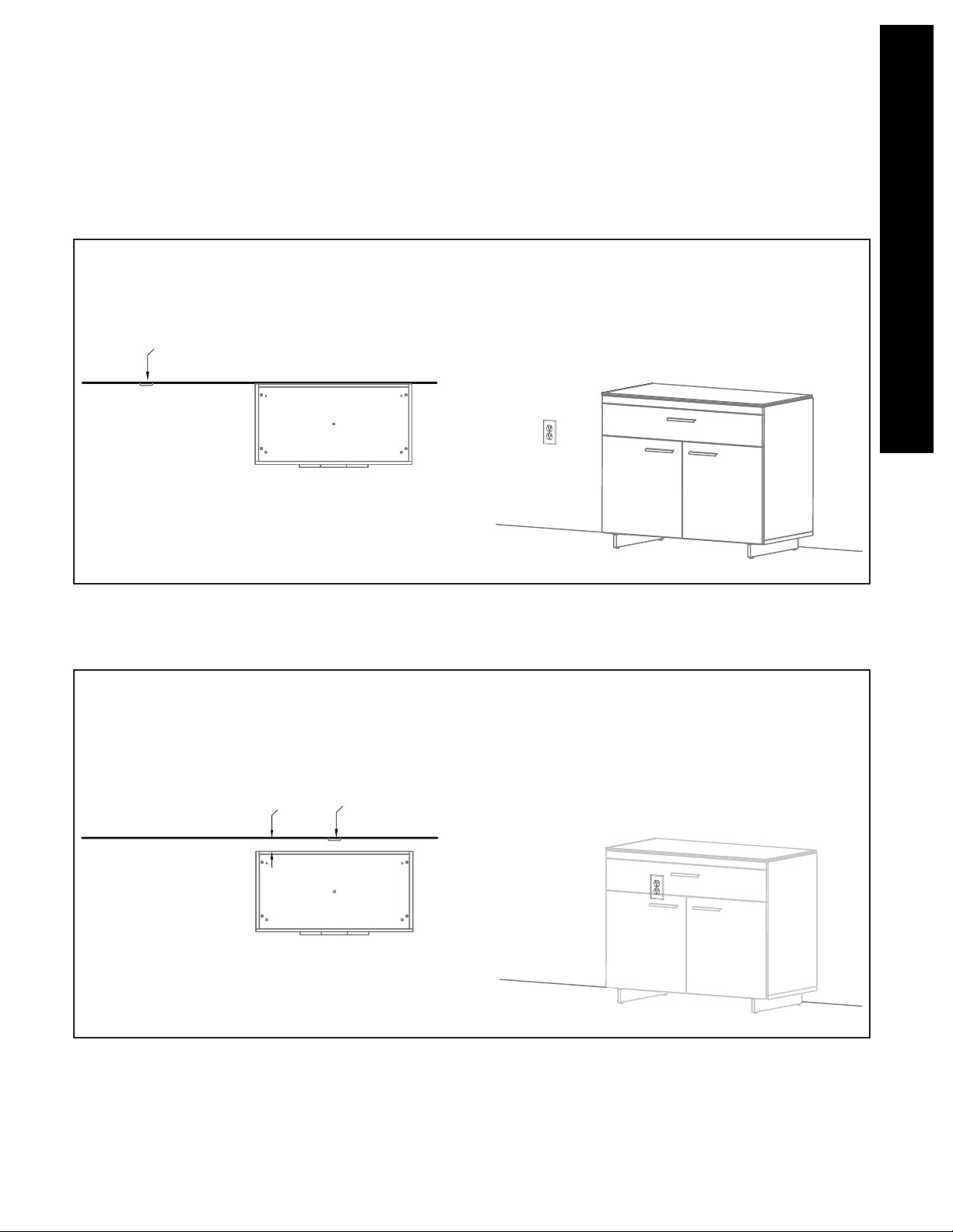
Power & Placement
This page outlines two scenarios:
Scenario 1
If cabinet is NOT blocking an AC power
outlet, it may be positioned close to the wall.
Power
Top View
Consumer Considerations
Scenario 2
If cabinet is going to block an AC power
outlet, position cabinet approximately 3” from
wall. Low profi le extension plugs may be
used to reduce the amount of space required
in this application.
3"
Top View
Power
5
Page 6

Corner Desk
Model 6019
Your SEQUEL
for easy assembly.
Carefully follow this procedure to prevent
any damage.
step 1
Do not use power tools for assembly of this product.
®
6019 Furniture is engineered
Placement and
Maintenance
SEQUEL® 6019 Furniture is designed for
indoor use on level floors. Clean glass with
glass cleaner, and steel parts and wood
veneer with a moist cloth.
Unpack and identify the components.
The assembly workspace should be a
non-marring surface such as carpet. For
missing hardware pieces, please contact
BDI Customer Service at customerservice@
bdiusa.com. For all other concerns, please
contact your BDI Retailer.
D
.
.
K
K
C
E
E
H
D
H
C
Hex Wrench 4mm x 1
A
Hex Wrench 3mm
x 1 (for Leveler
B
adjustment)
1/4-20 5/8” Machine
Screws 4mm Socket
C
Drive x 4
1/4-20 1/2” Flat Head
Screws 4mm Socket
D
Drive x 4
Rubber Stem Bumpers
E
x 3
1/4-20 60mm Machine
Screws 4mm Socket
F
Drive x 6
Cardboard Template x 1
G
Desk Frame Assembly x 1
H
Corner Leg x 1
I
Corner Leg Cover
J
Glass Top x 1
K
F
F
J
G
G
J
I
I
L
L
6
Leveler x 1
L
Velcro Straps x 6
M
Plastic Clips x 6
N
Magnets x 4
O
Page 7

Template
Position the Template (G) in the desired
location where the corner desk will
be positioned, followed by the Sequel
cabinets. Align the side of the cabinet with
the outside edge of the template. NOTE:
Cabinets’ top glass are not installed.
G
G
step 2
Plan View
Room View
7
Page 8

step 3
Wire Management
(Optional)
For the purpose of wire management,
use Plastic Clip (N) to install Velcro Straps
(M) to outside perimeter of Desk Frame
Assembly (H).
M x 6
N x 6
8
Page 9

A
C x 4
step 4
Attach Leg to Desk
Frame
While the second person holds the desk
frame on its side position, attach Corner
Leg (J) to the underside of Desk Frame
Assembly (H) using the Hex Wrench (A)
and Machine Screws (C).
H
J
9
Page 10

step 5
Attach Desk Frame
to Cabinets
With the help of another person, carefully
lower Desk Frame Assembly (H) onto the
adjacent cabinets (Sequel Models 6014,
6015, 6016, or 6017). Adjust frame so that
the holes are aligned with the threaded
inserts on top of the cabinets. Once holes
are aligned, install Flat Head Screws (D)
using Hex Wrench (A).
A
D x 4
10
Page 11

Bumpers & Template
Install Rubber Stem Bumpers (E). At this
time, the cardboard template may be
removed.
step 6
E x 3
11
Page 12

step 7
Install Glass
With the help of another person, carefully
lower the Glass Top (K) onto the frame.
Register the steel discs on underside of
glass into the holes on the frame; then
attach the glass using Machine Screws (F)
and Allen Wrench (A).
NOTE: Do not over-tighten screws!
A
F x 6
12
Page 13

CAUTION:
When setting up multiple
workstations, leave at least
1" between each station.
Failure to do so may result in
damage to tempered glass
work surfaces.
step 8
Plan View
1"
Install Glass
Carefully lower the glass panel onto the
Sequel Cabinet (Refer to individual cabinet
instructions).
13
Page 14

step 9
Magnets
Located inside the Corner Leg (I) are 4
Magnets (O) that may be peeled and
adhered to the rear side of a power strip
(not included).
step 8
Leveler
If needed, adjust leveler on Corner Leg
using 3mm Hex Wrench (B).
B
B
14
Page 15

step 9
step 10
Corner Leg Cover
Upon completion of wire management,
magnetically attach the Corner Leg Cover
(J) to the front of the Corner Leg (I).
15
Page 16

16
BDIUSA.COM
Designed by Matthew Weatherly.
These distinctive product confi gurations are protected
by US and international patents, trade dress, and/or
copyright laws. “Sequel” and BDI are trademarks of
Becker Designed, Inc. All Rights reserved. ©2011, BDI
Made in Taiwan. 6019REV052611v1
 Loading...