

Page 1
assembly instructions
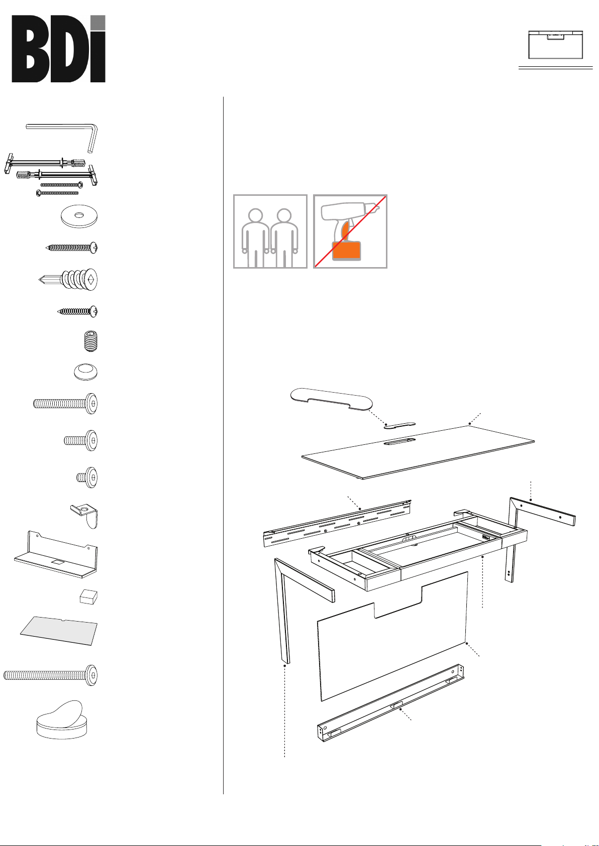
Component List
sequel
®
6004
wall-mounted desk
H - Hex Wrench x 1
I -Toggle Anchor Kit x 2
J - Washer x 6
K - Wood Screw x 4
L - Drywall Anchor x 2
M - Drywall Screw x 2
N - Set Screw x 4
bdiusa.com customerservice@bdiusa.com
Placement and Maintenance
Sequel® Home Office Furniture is designed for indoor use. Clean glass
with glass cleaner, and steel parts and wood veneer with a moist cloth.
Your Sequel® Home Office Furniture is engineered for easy assembly.
Carefully follow this procedure to prevent any damage.
Do not use power tools for assembly of this product.
TWO PERSON ASSEMBLY
Step 1
Unpack and identify the parts listed below. The assembly workspace
should be a non-marring surface such as carpet. For missing hardware
pieces, please contact BDI Customer Service at customerservice@
bdiusa.com. For all other concerns, please contact your BDI Retailer.
O - Adhesive Dot x 4
P - 1/4-20 x 38 mm Screw
x 4
Q - 1/4-20 x 12 mm Screw
x 4
R - 1/4-20 x 6mm Screw
x 4
S - Kick Panel Stop x 2
T - Power Strip Bay x 1
U - Adhesive Bumper x 2
V - Drawer Liner x 1
W -1/4-20 x 58mm Screw
x 3
G - Wire Management Lid x 1
F - Top Glass x 1
CR - Right Desk Side x 1
A - Wall Attachment Rail x 1
B - Drawer Assembly x 1
E - Kick Panel x 1
X - Adhesive Foam/Magnet
x 2
Designed by Matthew Weatherly.
These distinctive product configurations
are protected by US and international
patents, trade dress, and/or copyright laws.
“Sequel” and BDI are trademarks of Becker
Designed, Inc. All Rights reserved. ©2014
Becker Designed, Inc.
Made in Taiwan. 6004REV012615v3
D - Wire Management Trough x 1
CL - Left Desk Side x 1
1
Page 2
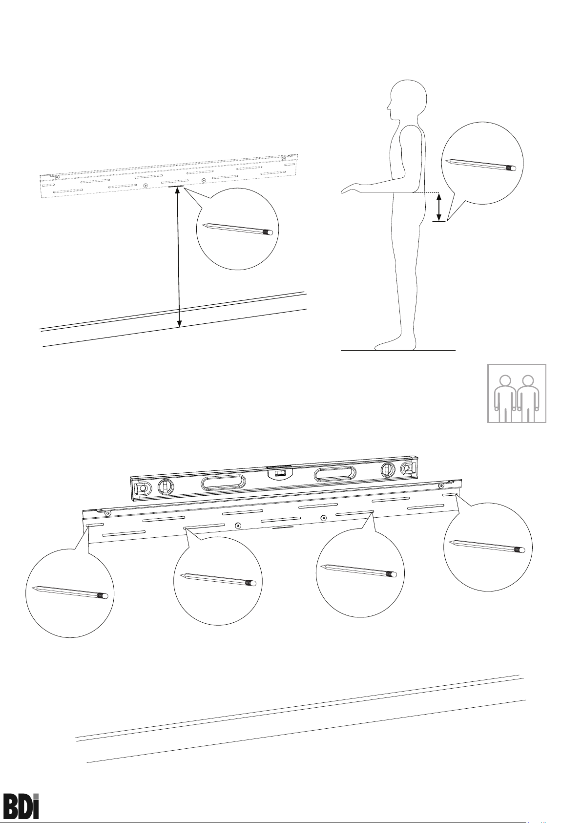
Step 2
The desk can be mounted at any height desired. For a sitting desk, mark the center of the
desk in its desired location 24.8 in/63 cm from the floor. For a standing desk, measure and
mark 4.5 in/11.4 cm from the bottom of your elbow at a 90º position.
Standing
4.5 in/ 11.4 cm
Sitting 24.8 in/ 63 cm
Step 3
Align the bottom of the Wall Attachment Rail (A) to the marked line and level. While holding
the leveled Wall Attachment Rail (A), allow the second person to outline the outermost holes
on the Wall Attachment Rail (A) and mark within each outline. Make two additional marks
within the slots of Wall Attachment Rail (A).
A
TWO PERSON ASSEMBLY
sequel
60 04 wa l l -mo u n t ed de s k
®
2
assembly instructions
bdiusa.com customerservice@bdiusa.com
Page 3
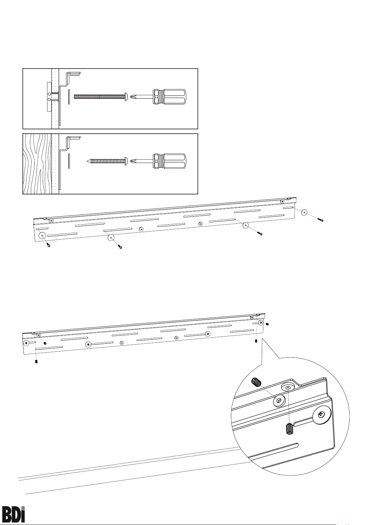
Step 4
Determine which wall attachment method below is needed to attach Wall Attachment Rail
(A) to the wall at each of the marks from the previous step. Follow instructions included in the
Toggle Anchor Kit (I) for proper installation of Toggle Anchors. If installing into a masonry wall,
please contact your local hardware store for preferred method of attachment.
A
Sheet Rock: (I) Toggle Anchor
(A) Wall Attachment Rail
I
J
I-S
A
(I-S) Toggle Anchor Screw
(J) Washer
Wooden Beam: (A) Wall Attacment Rail
(K) Wood Screw
J
K
(J) Washer
J
J
J
A
J
Step 5
Install Set Screws (N) into threaded holes of Wall Attachment Rail (A) using Hex Wrench (H).
N
N
N
A
N
N
A
sequel
®
60 04 wal l -m ou n t e d des k
N
3
assembly instructions
bdiusa.com customerservice@bdiusa.com
Page 4

Step 6
With the Drawer Assembly (B) upside down, attach Desk Sides (CL, CR) with Screw (P)
using Hex Wrench (H). Apply Adhesive Dots (O) to the back edge of Desk Sides (CL, CR) at
the top and bottom.
CL
O
O
CL CR
B
P P
P P
O O
Step 7
P
P
TWO PERSON ASSEMBLY
With the help of another person, carefully lower Wire Management Trough (D) between the
Desk Sides (CL, CR) and align holes. Attach Wire Management Trough (D) to Desk Sides
(CL, CR) with Screw (Q) using Hex Wrench (H).
O
CR
D
D
Q
Q
CR
CL
sequel
®
60 04 wal l -m ou n t e d des k
4
assembly instructions
bdiusa.com customerservice@bdiusa.com
Page 5

Step 8
Attach Kick Panel Stops (S) to the back holes of Drawer Assembly (B) using Screw (R) and
Hex Wrench (H).
B
R
S
B
Step 9
Apply Adhesive Bumpers (U) to the bottom of the back side of Power Strip Bay (T).
U
sequel
60 04 wal l -m ou n t e d des k
®
T
U
5
assembly instructions
bdiusa.com customerservice@bdiusa.com
Page 6

Step 10
Secure Power Strip Bay (T) to Wall Attachment Rail (A) using Screw (R) and Hex Wrench (H).
A
R
R
T
Step 11
With the help of another person gently lower the Desk Assembly onto the Wall Attachment
Rail (A). Ensure the hooks of the Desk Assembly are engaged with the Wall Attachment Rail
(A) before letting go of the assembly.
A
TWO PERSON ASSEMBLY
A
sequel
®
60 04 wal l -m ou n t e d des k
6
assembly instructions
bdiusa.com customerservice@bdiusa.com
Page 7

Step 12
Center the Desk Assembly within the Wall Attachment Rail (A) using the notches in the Wall
Attachment Rail (A) as a guide.
Notch
A
Step 13
Using Hex Wrench (H), adjust Set Screws (N) on Wall
Attachment Rail (A) to create a level work surface that is flush
against wall before moving to Step 14.
A
N
Down
Up
In
Out
N
A
sequel
60 04 wal l -m ou n t e d des k
®
7
assembly instructions
bdiusa.com customerservice@bdiusa.com
Page 8

Step 14
Duplicate the wall attachment method used on the outermost screws from Step 3 for attaching
Wire Management Trough (D) to the wall. If Toggle Anchors were used on Step 3, use
standard Drywall Anchors (L) for this step. Attach Wire Management Trough (D) to wall
using Screw and Washer (J) combination. DO NOT OVERTIGHTEN!
B
D
J
D
J
Step 15
With the help of another person gently lower Top Glass (F) onto Drawer Assembly (B) and
fasten into place using Screw (W) and Hex Wrench (H). With the grippy side facing down,
insert Drawer Liner (V)into drawer body.
F
B
W
TWO PERSON ASSEMBLY
V x 1
sequel
®
60 04 wal l -m ou n t e d des k
W x 3
W
W
8
assembly instructions
bdiusa.com customerservice@bdiusa.com
Page 9

Step 16 (Optional)
Remove Adhesive Foam/Magnets (X) from the Power Strip Bay (T). Peel film from
side of the Adhesive Foam/Magnets (X) and attach to clean, dry back side of AC power
strip (not included). Cleaning of power strip surface with rubbing alcohol will ensure
best adhesive bond. **UNPLUG POWER STRIP FROM POWER SOUCE BEFORE
CLEANING**
Attach AC power strip/surge protector (not included) on platform of
Power Strip Bay (T) as shown in illustration below.
1.
2.
Use the slot holes provided to run all wire to and from the desk. Keep
all wire behind the folded metal lips. Failure to do so will prevent Kick
Panel (E) from attaching properly.
3.
X
X
* AC Power Strip Not Included
sequel
60 04 wal l -m ou n t e d des k
®
T
9
assembly instructions
bdiusa.com customerservice@bdiusa.com
Page 10

Step 17
Once all the electrical wire are routed, install Kick Panel (E) as shown below. The rear side
of the panel has magnets that will hold it into place. Place Wire Management Lid (G) into
opening of Top Glass (F).
G
F
E
sequel
60 04 wal l -m ou n t e d des k
®
10
assembly instructions
bdiusa.com customerservice@bdiusa.com
 Loading...