

Page 1
a s s e m b l y i n s t r u c t i o n s
EILEEN & EILEEN BLANC
51 56 & 5157
bdiusa.com cust omerservice@bdiusa.com
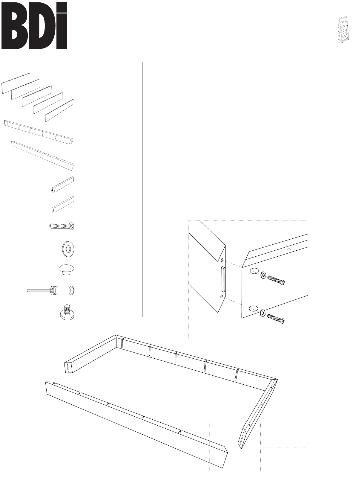
Component List
A1 - Glass Shelf x 1
A2 - Glass Shelf x 1
A3 - Glass Shelf x 1
A4 - Glass Shelf x 1
A5 - Glass Shelf x 1
Right Frame x 1
Left Frame x 1
Top Frame x 1
Bottom Frame x 1
D - Machine Screw x 8
Eileen Shelf is engineered for easy assembly. Carefully follow this
procedure to prevent any damage.
Placement and Maintenance
Eileen Shelf is designed for indoor use on level floors. Clean
glass with glass cleaner, and steel parts and wood veneer with a
moist cloth.
Step 1
Unpack and Identify
Unpack and identify the components at left. The assembly
workspace should be a non-marring surface such as carpet. For
missing hardware pieces, please contact BDI Customer Service
at customerservice@bdiusa.com. For all other concerns, please
contact your BDI Retailer.
Step 2
Assemble wood frame
Connect Left Frame and Right Frame with Top Frame and
Bottom Frame using Machine Screw (D), Washer (E) and Hex
Drive (G).
E - Washer x 8
F - Rubber Bumper x 2
G - Hex Drive
H - Leveler x 2
Bottom Frame
E x 8
D x 8
Right Frame
Left Frame
Top Frame
Designed by Matthew Weatherly.
These distinctive product configurations are protected by US and international patents, trade dress, and/or copyright laws.
BDI is trademark of Becker Designed, Inc.
All rights reserved. ©2010, BDI
Made in China. 5156REV071813v3
1
Page 2
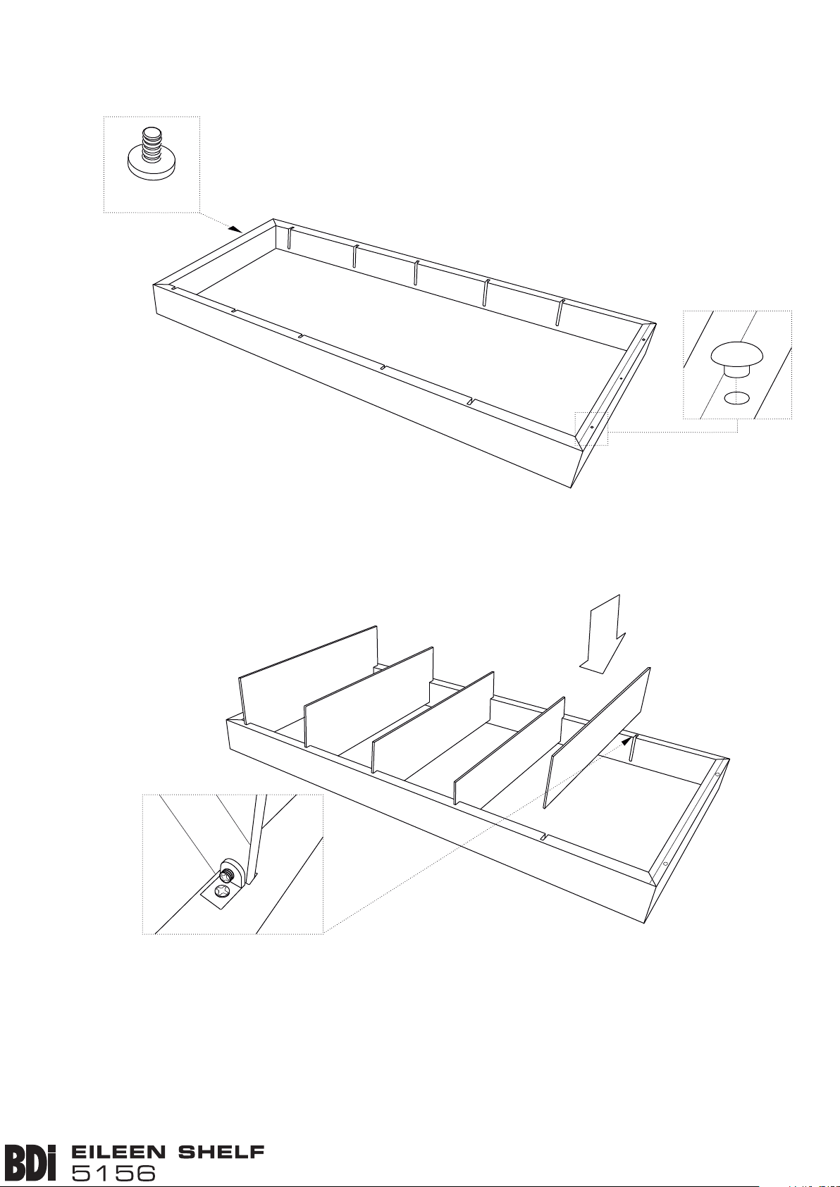
Step 3
Install Levelers and Rubber Bumper Inserts
Install Levelers (H) and Rubber Bumper Inserts (F) as shown
below.
H x 2
F x 2
Step 4
Install Glass Shelves
Install glass shelves to all slot locations on left frame and right
frame.
A1
A2
A3
A4
A5
Step 5
Secure Glass Shelves
Once shelves have been installed, tighten the plastic threaded
insert on the bottom of shelf bracket using a Phillips screwdriver.
2
bdiusa.com customerservice@bdiusa.com
assembly i nstructio ns
Page 3

Step 6
Once step 4 and 5 have been completed, lift assembled Eileen
against the wall.
1/8”
Side Elevation
The rear edge of all shelves
(except bottom shelf) should be
approximately 1/8" from the wall.
Step 6 - Install Tipping Restraint Kit.
On the rear side of the top frame, there is a pre-drilled
hole for installing the HH510 Furniture Tipping Restraint Kit
(included).
This tip restraint must be attached to a wall stud using the
2" screw enclosed.
1. Attach a bracket to the back top rail or back top edge of
the shelf using the 5/8" screw provided, through the smaller
hole in the bracket.
2. Determine where the shelf is to be placed and mark
location on the wall over a wall stud for the wall bracket hole
approximately 2” below the mounting bracket secured to the
back of your shelf. Attach to the wall stud, using the 2" screw
provided, through the smaller hole.
3. Place the shelf into position so both mounting brackets are
vertically in line.
5/8" Screw
To Mirror
Restraint Strap
Approx. 2"
To Wall
2" Wall Screw
Approx. 2”
Wall Screw
Restraint Strap
4. Lace the end of the restraint strap through the larger hole
in each bracket. Bring both ends together and slide the flat
end through the locking end and draw it through until all
slack is removed.
5. Confirm that strap is securely laced and locked.
3
*Note HH-510 Furniture Tipping Restraint Kit
is supplied by Walter of Wabash. For further
information, visit www.walterofwabash.com
assembly i nstructio ns
bdiusa.com customerservice@bdiusa.com
 Loading...