

Page 1
PHASE
51 30
a s s e m b l y i n s t r u c t i o n s
bdiusa.com cust omerservice@bd iusa.com
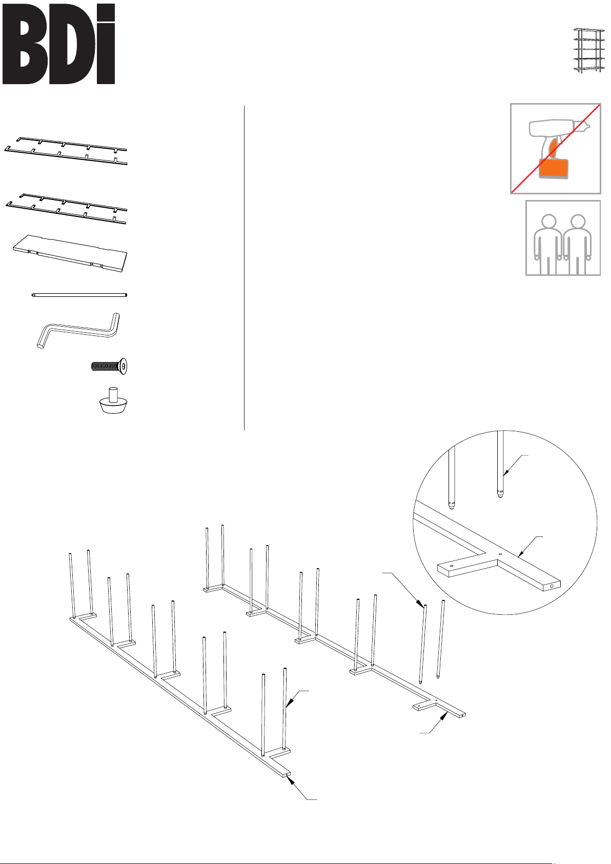
Component List
A1 - Front Support
x 1
A2 - Front Support
x 1
B1 - Back Support
x 1
B2 - Back Support
x 1
C - Wood Shelf x 5
D - Attachment Rod
x 20
E - 4mm Hex Wrench
x 1
F - M6 x 20mm Screw
x 20
G - Leveler x 4
Carefully follow this procedure to prevent any
damage.
Placement and Maintenance
Phase shelf is designed for indoor use on level
floors. Clean steel parts and wood veneer with a
moist cloth.
Many wood surfaces are subject to fading under
direct sunlight. BDI’s unique Graphite finish has
properties that make it more sensitive than others.
Please avoid placing BDI’s Graphite finish in direct
sunlight.
Step 1
TWO PERSON ASSEMBLY
Unpack and Identify
Unpack and identify the components at left. The assembly
workspace should be a non-marring surface such as carpet. For
missing hardware pieces, please contact BDI Customer Service
at customerservice@bdiusa.com. For all other concerns, please
contact your BDI Retailer.
Step 2
Attach Rods to Front Supports
With the holes facing up, place Front Supports (A1, A2) on soft
surface in order to prevent
damage. Hand tighten
Attachment Rods (D) to Front
D
Supports (A1, A2).
Designed by Matthew Weatherly.
These distinctive product configurations are protected by US and international
patents, trade dress, and/or copyright laws.
BDI is trademark of Becker Designed, Inc.
All rights reserved. ©2013, BDI
Made in China. 5130REV01292014v3
A2
D
D
A2
A1
1
Page 2
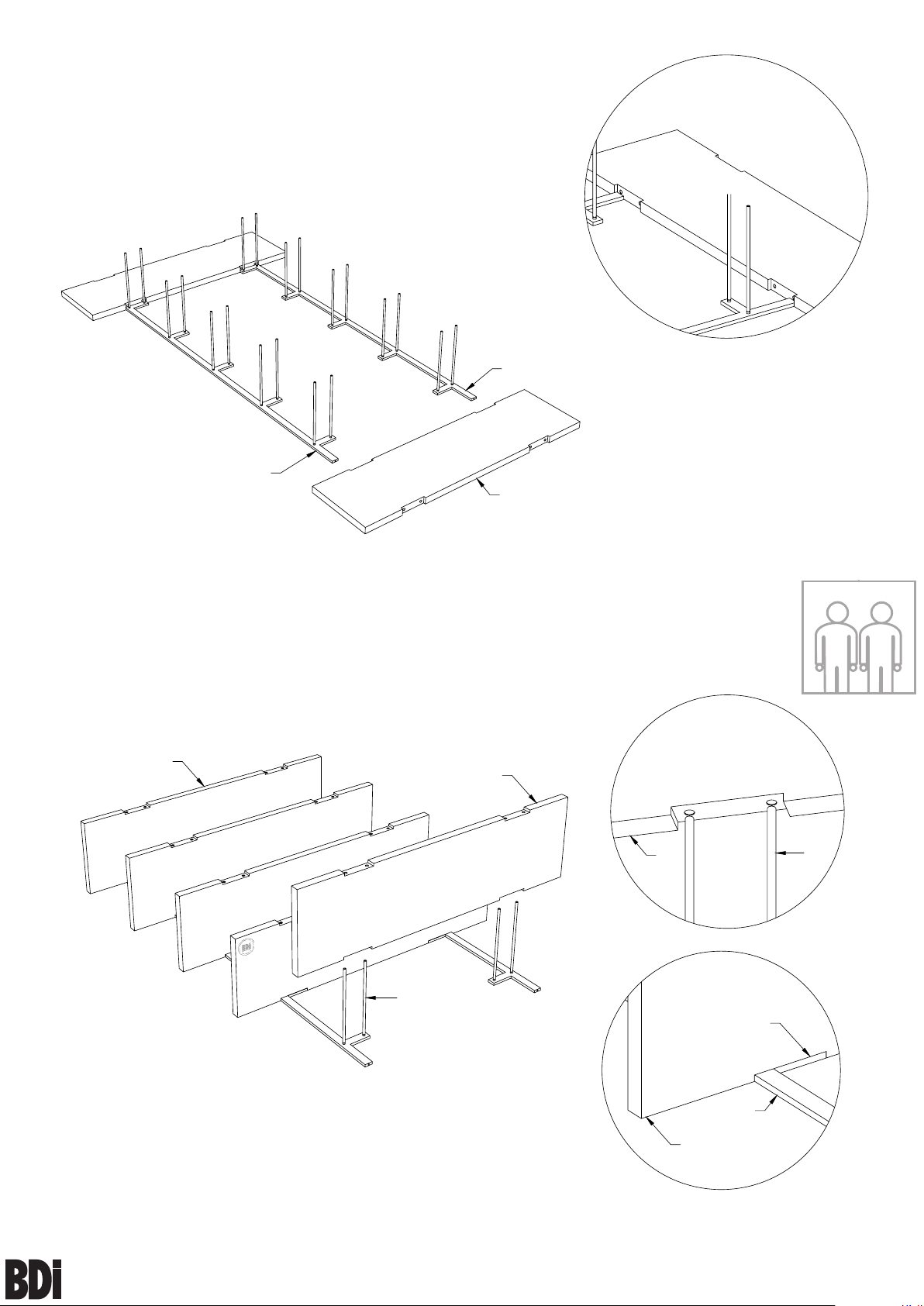
Step 3
Space Front Supports
Lay two Wood Shelves (C) on each end of the Front Frames
(A1, A2) so that the ends of the Frames are laying within the
indented spaces of the Wood Shelves (C).
A2
A1
C
Front Supports
spaced properly.
Step 4
Install Wood Shelves
Position each Wood Shelf (C) over the respective Attachment
Rods (D) and carefully lower into place so that Wood Shelf rests
flush against Front Supports (A1, A2). Some shelves may be
easier to install than others due to the multiple attachment points.
*Gentle force may be required.
C
C
D
C
Shelf resting
flush to metal.
TWO PERSON ASSEMBLY
D
pha s e
51 30
2
A1
C
assembly instr uctions
bdiusa.com customerservice@bdiusa.com
Page 3

Step 5
Align Back Supports
Lay the Back Supports (B1, B2), with the countersunk holes to
the outside, onto the Wood Shelves (C).
Countersunk
side facing up.
B2
B1
C
Step 6
Attach Back Supports & Turn Shelf Upright
Screw Back Support (B1, B2) to assembly using the Hex Wrench
(E) and Screws (F). Do not overtighten. At this time insert
Levelers (G) into the bottom of all the Frames. Lift assembled
Phase upright.
C
F
B1
B2
F
G x 4
C
pha s e
51 30
3
assembly instr uctions
bdiusa.com customerservice@bdiusa.com
Page 4

Step 7
Align Wood Shelves with Metal
Make sure all Wood Shelves (C) are aligned and flush with the
Metal Supports (A1, A2, B1, B2). If anything is misaligned or
unevenly spaced, tap the Shelf (C) and Supports (A1, A2, B1, B2)
to its appropriate position. Once everything is flush and properly
spaced completely tighten the Screws (F) with Hex Wrench (E).
Correctly Aligned Incorrectly Aligned
Step 8
Retighten Wood Shelves
Retighten Screws (F) with Hex Wrench (E) on all Wood Shelves
(C) after a few weeks of use, as Wood Shelves (C) may contract
and fasteners may loosen due to varying humidity levels.
Step 9
Install Tipping Restraint Kit.
There is no pre-drilled hole on the rear side of the top shelf
for installing the HH510 Furniture Tipping Restraint Kit
(included).
This tip restraint must be attached to a wall stud using the
2" screw enclosed.
1. Determine where shelf is to be placed and mark the
location of a wall stud on the back edge of the top shelf. Drill
the provided 5/8” screw into the back edge of the top shelf at
the stud mark, attaching through the smaller hole in the
bracket.
2. Line the shelf back up to the determined wall stud and
mark the location on the wall for the wall bracket hole,
approximately 1” below the mounting bracket secured to the
back of the shelf. Attach to the wall stud, using 2” screw
provided, through the smaller hole of the bracket.
3. Place the shelf into position so both mounting brackets are
vertically in line.
4. Lace the end of the restraint strap through the larger
hole in each bracket. Bring both ends together and slide the
flat end through the locking end and draw it through until all
slack is removed.
5. Confirm the strap is securely laced and locked.
5/8" Screw
To Mirror
Restraint Strap
Approx. 2"
To Wall
2" Wall Screw
*Note HH-510 Furniture Tipping Restraint Kit
is supplied by Walter of Wabash. For further
information, visit www.walterofwabash.com
pha s e
51 30
4
assembly instr uctions
bdiusa.com customerservice@bdiusa.com
 Loading...