

Page 1

19 November 2008 BD X-Monitor 2 # 1080500 1
B
D
B
D
Digital Gauge Monitoring Package
*** READ THIS MANUAL & DISCLAIMER COMPLETELY BEFORE INSTALLING THIS PR ODUCT ***
Ship: #88 – 446 Harrison St, Sumas, WA 98295 Mail: PO Box 231, Sumas, WA 98295
X--
X
A10 – 33733 King Rd, Abbotsford, BC, Canada V2S 7M9
Ph: 604.853.6096 Fax: 604.853.8749 Internet: www.bd-power.com
M
M
Installation Instructions
P/N#
Installation Manual P/N#: I1080500
O
O
BD Engine Brake Inc
N
N
1080500
I
I
T
T
O
O
R
R
2
2
Page 2

19 November 2008 BD X-Monitor 2 # 1080500 2
TABLE OF CONTENTS
Accessories......................................................................................................................4
Pillar Mounts.............................................................................................................4
Others.......................................................................................................................4
Tools Needed....................................................................................................................4
Pre-Installation.................................................................................................................4
Installation........................................................................................................................5
Thermocouple Installation ..............................................................................................6
Vehicle Specific Placement.......................................................................................6
Dodge 1998-2006............................................................................................6
Ford 1999-2006...............................................................................................6
GM 2001-2006.................................................................................................7
Generic Installation of the Thermocouple.................................................................7
Pre-Turbo Installation ......................................................................................7
Post-Turbo Installation.....................................................................................8
Wiring Installation............................................................................................................8
Dodge 1998-2002 5.9L.............................................................................................8
Dodge 2003-2006 5.9L...........................................................................................12
Optional Ram Xpower Control #1800505...............................................................15
X-Power Control Wiring Diagram...................................................................16
Optional Ram Fuel Pressure Monitoring Kit #1080150...........................................17
Rail Pressure Sensor (3rd Gen Dodge Only 2003-06) ...................................17
Auxiliary Fuel Pressure..................................................................................17
Wiring Diagram (Fuel Pressure)....................................................................18
Ford 1999-2003 7.3L ..............................................................................................19
Ford 2003-2006 6.0L ..............................................................................................22
Duramax 2001-06...................................................................................................25
Universal Wiring Diagram .............................................................................................28
Display Functions..........................................................................................................29
Main Menu..............................................................................................................29
Display Menu.................................................................................................30
Alerts Menu....................................................................................................30
Defueling Settings ................................................................................30
Warnings..............................................................................................31
Setup .............................................................................................................31
Backlight...............................................................................................33
Technical Support..........................................................................................................33
A10 – 33733 King Rd, Abbotsford, BC, Canada V2S 7M9
Ship: #88 – 446 Harrison St, Sumas, WA 98295 Mail: PO Box 231, Sumas, WA 98295
Ph: 604.853.6096 Fax: 604.853.8749 Internet: www.bd-power.com
BD Engine Brake Inc
Page 3
19 November 2008 BD X-Monitor 2 # 1080500 3
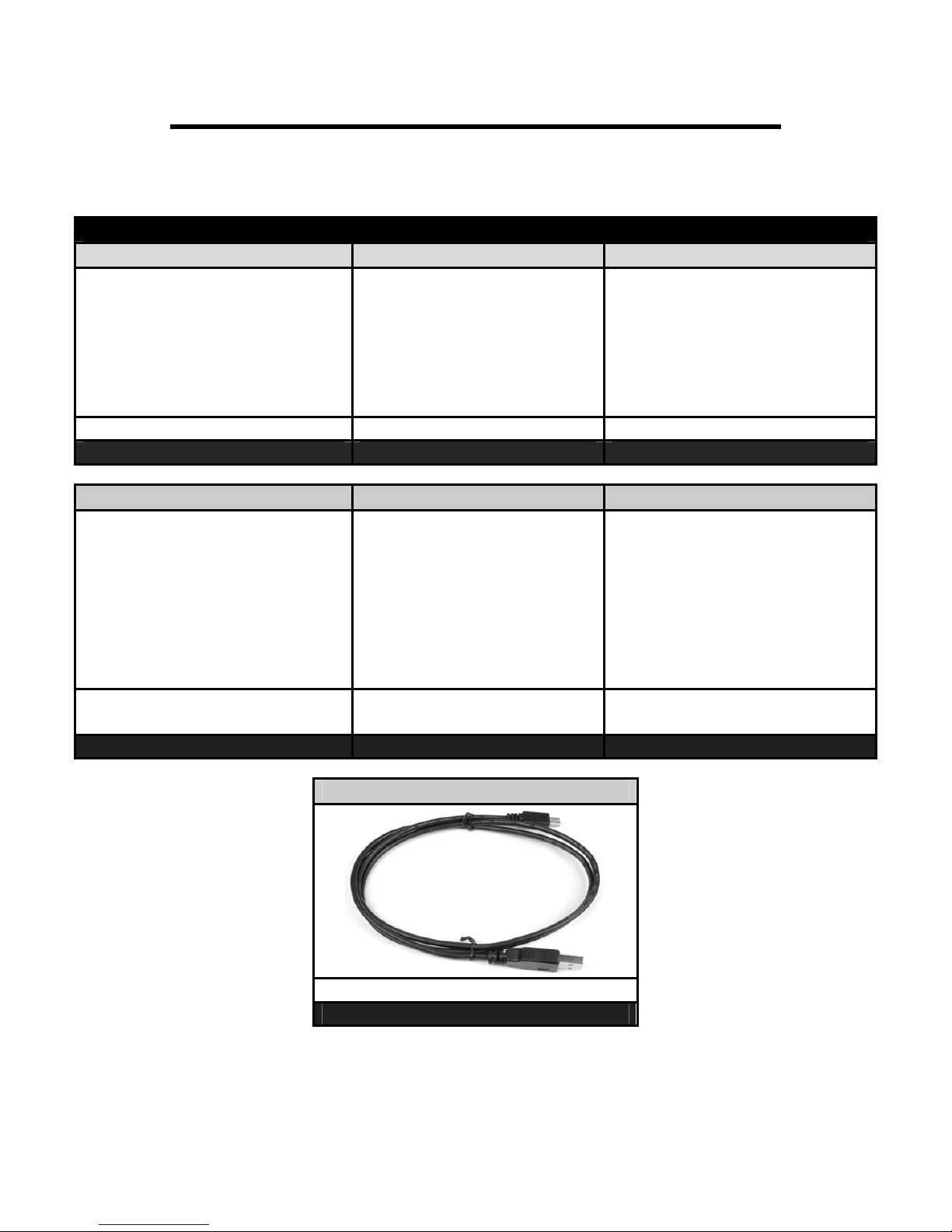
KIT CONTENTS:
Please check to make sure that you have all the parts listed in this kit before you start
the disassembly your truck.
1080500 – BD X2 Monitor
1805000 1800508 1800502
X2 Monitor Assembly
Qty: 1 Qty: 1 Qty: 3
Monitor Holder
Thermocouple w/ Harness
1800503 1800504 1800506
Sensor Fitting Adapters
Qty: 3 Qty: 1 Qty: 1
Main Harness
(includes oil sensor)
X2 Installation Care Kit
1800507
A10 – 33733 King Rd, Abbotsford, BC, Canada V2S 7M9
Ship: #88 – 446 Harrison St, Sumas, WA 98295 Mail: PO Box 231, Sumas, WA 98295
Ph: 604.853.6096 Fax: 604.853.8749 Internet: www.bd-power.com
USB Cable (for internet updates)
Qty: 1
BD Engine Brake Inc
Page 4
19 November 2008 BD X-Monitor 2 # 1080500 4
Accessories
Pillar Mounts
P/N# Application
1080570
1080571
1080572
P/N# Application
1080551
1080553
1080552
P/N# Application
1080560
1080561
Powerstroke 1999-2002 7.3L
Powerstroke 2003-2007 6.0L
Powerstroke 2007-2008 6.4L
Cummins 1998½-2002 24V w/ Speaker
Cummins 1998½-2002 24V w/o Speaker
Cummins 2003-2007 24V HPCR
Duramax 6.6L 2001-2007 w/o Speaker
Duramax 6.6L 2001-2007 w/ Speaker
Others
Fuel Pressure Monitoring Kit
P/N# Application
1080150
1800505
All
Ram Xpower Control
Tools Needed
Power Drill, 21/64” Drill Bit, 1/8” NPT Tap, Teflon Tape
Pre-Installation
The BD X2 Monitor is a powerful monitor that has the ability to monitor up to 7 engine
parameters, with up to 4 displaying at a time. However, the X2 still monitors up to all 7
parameters simultaneously with the option to set warnings for up to 6 parameters. Defueling options are available based upon 4 of these parameters. While monitoring these
parameters, the X2 also records the highest/lowest value of all parameters being
monitored. In addition to recording the min/max readings you also have the ability to data
log these parameters. The X2 also has the ability to control multiple power modules.
There are many more features to the X2 which will be explained in detail further on in the
manual.
A10 – 33733 King Rd, Abbotsford, BC, Canada V2S 7M9
Ship: #88 – 446 Harrison St, Sumas, WA 98295 Mail: PO Box 231, Sumas, WA 98295
Ph: 604.853.6096 Fax: 604.853.8749 Internet: www.bd-power.com
BD Engine Brake Inc
Page 5

19 November 2008 BD X-Monitor 2 # 1080500 5
Installation
Choose a location in your vehicle where you want to mount the X2. It is important to do a
test fitting to make sure that is plainly visible while driving, but not an obstruction of your
driving view. We recommend beside the A-Pillar on the driver’s side. The rest of these
instructions assume that you chose this location. If you choose a different location, you
may have to use different techniques to route the cable harness under the dash.
Loosen or remove the A-Pillar. You need the pillar to be loose enough to route the
connectors down the pillar and beside the dash. The ultimate goal is to get the 3
connectors on the end of the cable harness under the dash and below the steering
wheel. Most A-Pillars have plenty of room to route the cable and still install the A-Pillar
back in the factory position without any modifications. It is okay for the pillar to be tight
against the cable as long as it doesn’t have enough pressure to damage the harness.
Once the cable is routed, pull any slack down
under the dash, but leave enough room to stand
the X2 up in the mounted position.
Clip the assembled base onto the X2. Hold the
X2 with the base i
ntact in the posit
to mount it. Make sure the viewing angle is
correct for the location. If the base needs to be
adjusted, you may do so by using a #2 Phillips
head screwdriver. Simply loosen the 2 screws
holding the base onto the adjustable disk. Do not
remove the screws completely; just loosen them
enough to move the X2’s position. Once you
have your desired angle, tighten the screws.
There are two ways to secure the base to your dash. You may permanently mount it with
the 2 supplied screws or you can use the supplied double sided 3M Tape. This tape is
strong enough to hold your gauge in position and is also removable.
If Using Screws: Holding the X2 in place, carefully mark a spot on the dash on both sides
of the disk where the screw slots are located. Carefully drill a 1/8” hole in these spots for
a pilot hole. You want to make sure to try and drill in the center of the provided slots so
that you leave some room for adjustment. Holding the gauge back into place, carefully
install the screws into the pilot holes. Although the dashes are fairly thick it is important to
not over tighten the screws and strip the plastic material.
If Using Tape: Clean the desired mounting area and the bottom of the mount with the
provided alcohol wipe. Apply the double sided tape to the bottom of the mount. It is best
ion you want
A10 – 33733 King Rd, Abbotsford, BC, Canada V2S 7M9
Ship: #88 – 446 Harrison St, Sumas, WA 98295 Mail: PO Box 231, Sumas, WA 98295
Ph: 604.853.6096 Fax: 604.853.8749 Internet: www.bd-power.com
BD Engine Brake Inc
Page 6
19 November 2008 BD X-Monitor 2 # 1080500 6
to only peel one side of the tape protector off at a time. Once you are ready to mount it,
carefully stick it to the dash. Once it is in its desired location, press down firmly onto the
dash. It is best to apply pressure on all parts of the base that has the tape on so it takes a
good hold.
Thermocouple Installation
Vehicle Specific Placement
Please review the recommended positioning for the thermocouple for your specific
vehicle.
Dodge 1998-2006
On the passenger side of the
vehicle locate the exhaust
manifold. On the top side of the
manifold between cylinders #2
and #3 is the ideal location for the
thermocouple.
Ford 1999-2006
On the driver’s side of the
vehicle, locate the exhaust
manifold. You will need to drill
from underneath the vehicle. The
ideal location for the
thermocouple is located just as
the manifold turns up to the turbo
inlet pipe. Make certain that you
drill at an angle that will accept
the length of the thermocouple.
A10 – 33733 King Rd, Abbotsford, BC, Canada V2S 7M9
Ship: #88 – 446 Harrison St, Sumas, WA 98295 Mail: PO Box 231, Sumas, WA 98295
Ph: 604.853.6096 Fax: 604.853.8749 Internet: www.bd-power.com
BD Engine Brake Inc
Page 7
19 November 2008 BD X-Monitor 2 # 1080500 7
GM 2001-2006
Remove the passenger side
fender well. Once this is removed,
you will see the exhaust manifold.
Towards the rear of the manifold
there is a flange that the manifold
bolts to. Just in front of this flange
is the ideal place to drill for the
thermocouple.
Generic Installation of the Thermocouple
This section provides instructions for the generic installation of the thermocouple.
Pre-Turbo Installation
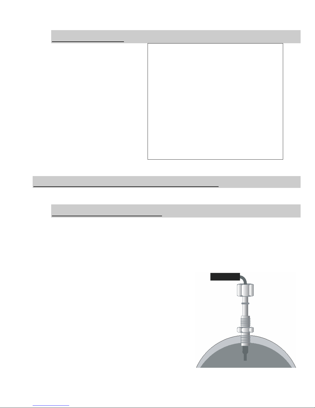
You must drill a 21/64 hole in your exhaust manifold. There are 2 ways to do this – the
best way is the way that makes you most comfortable. You can remove the manifold to
do this or you can do it on the vehicle while the engine is idling. It is also desirable to drill
a 1/8” pilot hole. Leaving the engine idling will allow any small shavings to safely exit the
exhaust. It is recommended to apply a small amount of grease to the drill bit before
drilling.
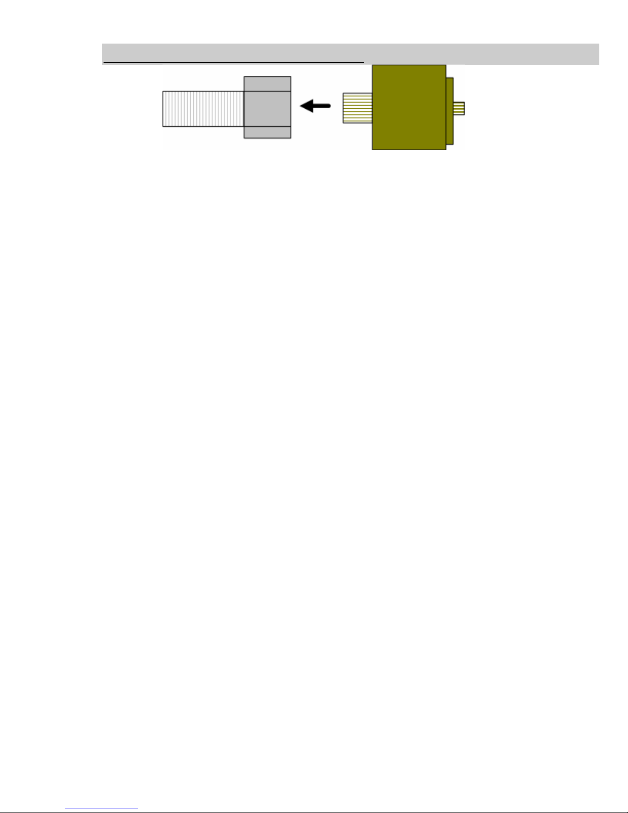
Use a 1/8-27 or 1/8NPT tap to make threads in the
hole you just drilled. You will not want to run the tap all
the way into the manifold. This is a tapered tap so the
threads at the top are larger than the ones on the
bottom. You need to tape it far enough to screw the
thermocouple bushing into the manifold.
Screw the thermocouple bushing into the manifold. Be
careful not to over tighten it.
Insert the supplied thermocouple into the bushing and
tighten the locking nut.
A10 – 33733 King Rd, Abbotsford, BC, Canada V2S 7M9
Ship: #88 – 446 Harrison St, Sumas, WA 98295 Mail: PO Box 231, Sumas, WA 98295
Ph: 604.853.6096 Fax: 604.853.8749 Internet: www.bd-power.com
BD Engine Brake Inc
Page 8

19 November 2008 BD X-Monitor 2 # 1080500 8
Post-Turbo Installation
Drill a 21/64 hole into your turbo down pipe. There is no need for the engine to idle or to
remove the exhaust piece from the truck. The metal shavings will simply exit the exhaust
system when you run the engine.
Use a 1/8-27 or 1/8NPT tap to make threads in the hole you just drilled. You will not want
to run the tap all the way into the manifold. This is a tapered tap, meaning that the
threads at the top are larger than the ones on the bottom. You need to tap it far enough
to screw the thermocouple bushing into the exhaust pipe.
Screw the thermocouple bushing into the pipe. Be careful not to over tighten because it is
easy to strip the threads in the thin exhaust pipe.
Insert the supplied thermocouple into the bushing and tighten the locking nut.
Wiring Installation
Dodge 1998-2002 5.9L
1. Find the lead wire. This is a 2-wire harness with an orange and black wire. The
larger connector needs to be connected to the thermocouple.
2. Route the lead wire across the engine bay to the driver’s side. Tie the lead wire out
of the way of any moving or hot parts to avoid damage to the wires.
3. On the driver’s side firewall there is a rubber plug. Cut a slit in the outer portion of
the plug to route the small connector and wire into the cab.
4. Plug the small 2-wire plug into the corresponding plug on the cable harness.
5. Lay wiring harness #1 out on your engine. The green plug will go inside the cabin
using the same location you routed the lead wire through.
6. Locate the engine’s MAP sensor. This is on the driver’s side of the engine and
behind the fuel filter canister. The year model determines the shape of the
connector.
a. For 1998-2000 trucks, the MAP sensor is round (triangle). There are 2 wires
in the top of the plug and 1 wire in the bottom of the plug. Connect the
supplied T-Tap to the wire that is on the bottom of the plug. This should also
be labeled pin “C” on the connector.
A10 – 33733 King Rd, Abbotsford, BC, Canada V2S 7M9
Ship: #88 – 446 Harrison St, Sumas, WA 98295 Mail: PO Box 231, Sumas, WA 98295
Ph: 604.853.6096 Fax: 604.853.8749 Internet: www.bd-power.com
BD Engine Brake Inc
Page 9

19 November 2008 BD X-Monitor 2 # 1080500 9
b. For 2001 trucks, the
MAP sensor is an
oval shape. It also
has 3 wires. Connect
the supplied wire tap
to pin “C” on the
plug. To locate pin C,
look at the back of
the plug where the
wires go into the plug
and the retaining clip
is on top, pin “C” is
on the right side.
c. For 2002 trucks, the MAP sensor is also an oval shape, but it also has a
plastic red lock that you m
ust remove to remove the sensor. It also has 3
wires. Connect the supplied T-Tap to the wire that is in the center of the plug.
If you have a power module installed,
you will need to connect to the same
wire on the module’s wiring harness to
receive an accurate reading. Only tap
the wire of the plug that is going into
the sensor. Do not tap the wire on the
factory plug when you are using a
power module. This will result in a
false reading.
7. Connect the blue wire to the TTap.
8.
Locate the Engine Coolant Temperature Sensor (ECT) on the front of the engine.
This is a 2-wire connector located on the top of the engine, in front of the valve
cover.
9. Connect the orange wire to the T-Tap.
10. Find the 1/8” male x ¼” female and the ¼” male x 1/8” female brass fittings supplied
in the kit.
11. Screw the ¼” male end of the brass fitting into the ¼” female fitting. Use Teflon tape
to make sure that it will not leak.
A10 – 33733 King Rd, Abbotsford, BC, Canada V2S 7M9
Ship: #88 – 446 Harrison St, Sumas, WA 98295 Mail: PO Box 231, Sumas, WA 98295
Ph: 604.853.6096 Fax: 604.853.8749 Internet: www.bd-power.com
BD Engine Brake Inc
Page 10

19 November 2008 BD X-Monitor 2 # 1080500 10
12. Screw the supplied 1/8” temperature sensor into the 1/8” female side of the brass
connector.
13. Locate test port #2 on your transmission.
This port is on the passenger side of the
vehicle. The transmission is round on the
front passenger side corner. Moving
towards the rear of the transmission you
will see an inset part of the transmission.
There is a small plug in the test port.
Remove the plug.
14. Using Teflon tape, screw the temperature
probe and fittings into the test port. Do
not over tighten.
Route the purple wire from the wiring harness to the temperature sensor.
15.
16. Remove the nut and washers from the sensor and install the purple wire. Replace
the washers and tighten the nut to secure the wire.
17. Go over the wiring harness and secure it to the vehicle, out of harms way using the
supplied wire ties. Keep all wires as far away from moving parts and hot parts of the
engine as possible.
18. Slide the green plug through the rubber grommet where you ran the lead wire. Pull
enough of the wire harness inside the cab so that the switch port connection (white
and black wires) and the black wire with the ring terminal and the red wire with the
fuse tap are inside the cab.
19. Find the bolt located by the firewall and remove it. Place the bolt through the ring
terminal of the black wire and screw it back into its location.
20. Open the fuse box, located on the inside of the truck on the driver’s side of the
dash. You will be required to open the driver’s side door to access the fuse
compartment.
21. Remove fuse #17 and install the fuse tap over the leg of the fuse. Re-install the
fuse.
22. Once everything is secure and installed, you will want to start your engine. The X2
comes pre-set for these 4 parameters. To make sure everything is installed
correctly, use these basic guidelines:
BD Engine Brake Inc
A10 – 33733 King Rd, Abbotsford, BC, Canada V2S 7M9
Ship: #88 – 446 Harrison St, Sumas, WA 98295 Mail: PO Box 231, Sumas, WA 98295
Ph: 604.853.6096 Fax: 604.853.8749 Internet: www.bd-power.com
Page 11

19 November 2008 BD X-Monitor 2 # 1080500 11
EGT temperatures should be in the 250-350°F (120-175°C) ranges, depending on
engine temperature and outside temperature. Boost pressure should read 0psi at
idle and up to 5psi while revving the engine at the idle position. ECT should be
similar to your factory gauge. If the vehicle is cold, it should read close to ambient
temperature and slowly rise.
Transmission temperature will most likely read ~100°F (35°C). It can take up to 20
miles, depending on the outside temperature, driving style and load to reach
temperatures above 100°F (35°C). Operating temperatures range from 110-180°F
(40-80°C) dependant upon load and driving style.
23. Using the supplied wire ties, tie up the wire and cable harness under the dash.
A10 – 33733 King Rd, Abbotsford, BC, Canada V2S 7M9
Ship: #88 – 446 Harrison St, Sumas, WA 98295 Mail: PO Box 231, Sumas, WA 98295
Ph: 604.853.6096 Fax: 604.853.8749 Internet: www.bd-power.com
BD Engine Brake Inc
Page 12

19 November 2008 BD X-Monitor 2 # 1080500 12
Dodge 2003-2006 5.9L
1. Find the lead wire. This is a 2-wire harness with an orange and black wire. The
larger connector needs to be connected to the thermocouple.
2. Route the lead wire across the engine bay to the driver’s side. Tie the lead wire out
of the way of any moving or hot parts to avoid damage to the wires.
3. On the driver’s side firewall there is a rubber plug. You can either pop the rubber
plug out or cut a slit in it to route the small connector and wire the cab.
4. Plug the small 2-wire plug into the corresponding plug on the cable harness.
5. Lay wiring harness #1 out on your engine. The green plug will go inside the cabin
using the same location you routed the lead wire through.
6. Locate the engine’s MAP sensor. This is on the driver’s side of the engine, next to
the valve cover. It has 4 wires coming from it.
A10 – 33733 King Rd, Abbotsford, BC, Canada V2S 7M9
Ship: #88 – 446 Harrison St, Sumas, WA 98295 Mail: PO Box 231, Sumas, WA 98295
Ph: 604.853.6096 Fax: 604.853.8749 Internet: www.bd-power.com
BD Engine Brake Inc
Page 13

19 November 2008 BD X-Monitor 2 # 1080500 13
7. Connect the supplied wire tap to pin “D”. When you look at the back of the plug
where the wires go into the plug and retaining clip is on top, pin “D” is on the right
side. If you have a power module installed, you will need to connect to the same
wire on the module’s wiring harness to receive an accurate reading. Only tap the
wire of the plug that is going into the sensor. Tapping the factory wire when using a
power module will result in a false reading.
8. Connect the blue wire to the wire tap.
9. Locate the Engine Coolant Temperature Sensor (ECT) on the front of the engine.
This is a 2-wire connector located on the top of the engine in front of the valve
cover.
10. Due to having various wire colors used by the factory it is recommended to use a
voltmeter to determine the correct wire. With the key in the on position, check
voltages on both wires. One wire should be ground or read .006 and the other wire
should read .9-3.5V. Connect the wire that has voltage on it. Once the proper wire
is determined, install the supplied T-Tap. On 2003-2004 models you should
connect to pin “2” as labeled on the top of the connector. On 2005-2006 models,
you should connect to pin “B” as labeled on top of the connector.
11. Connect the orange wire to the T-Tap.
12. Find the 1/8” male x ¼” female and the ¼” male x 1/8” female brass fittings supplied
in the kit.
13. Screw the ¼” male end of the brass fitting into the ¼” female fitting. Use Teflon tape
to make sure that it will not leak.
14. Screw the supplied 1/8” temperature
sensor into the 1/8” female side of
your brass connector.
15. Locate test port #2 on your
transmission. This port is on the
passenger side of the vehicle. The
transmission is round on the front
passenger side corner. Moving
towards the rear of the transmission
you will see an inset part of the
transmission. There is a small plug in
the test port. Remove the plug.
BD Engine Brake Inc
A10 – 33733 King Rd, Abbotsford, BC, Canada V2S 7M9
Ship: #88 – 446 Harrison St, Sumas, WA 98295 Mail: PO Box 231, Sumas, WA 98295
Ph: 604.853.6096 Fax: 604.853.8749 Internet: www.bd-power.com
Page 14

19 November 2008 BD X-Monitor 2 # 1080500 14
16. Using Teflon tape, screw the temperature probe and fittings into the test port. Do
not over tighten.
17. Route the purple wire from the wiring harness to the temperature sensor.
18. Remove the nut and washers from the sensor and install the purple wire. Replace
the washers and tighten the nut to secure the wire.
19. Go over the wiring harness and secure it to the vehicle, out of harms way using the
supplied wire ties. Keep all wires as far away from moving parts and hot parts as
possible.
20. Slide the green plug through the rubber grommet where you ran the lead wire. Pull
enough of the wire harness inside the cab so that the switch port connection (white
and black wires) and the black wire with the ring terminal are inside the cabin.
21. Find the bolt located by the firewall and remove it. Place the bolt through the ring
terminal of the black wire and screw it back into its location.
22. In the engine compartment, locate the red wire with the installed fuse tap.
23. Open the fuse box located under the hood on the driver’s side fender.
24. Remove fuse #28 and install the fuse tap over the leg of the fuse. Re-install the
fuse.
25. Once everything is secure and installed you will want to start your engine. The X2
comes pre-set for these 4 parameters. To make sure everything is installed
correctly, use these basic guidelines:
EGT temperatures should be in the 250-350°F (120-175°C) ranges, depending on
engine temperature and outside temperature. Boost pressure should read 0psi at
idle and up to 5psi while revving the engine at the idle position. ECT should be
similar to your factory gauge. If the vehicle is cold, it should read close to ambient
temperature and slowly rise.
Transmission temperature will most likely read ~100°F (35°C). It can take up to 20
miles, depending on the outside temperature, driving style and load to reach
temperatures above 100°F (35°C). Operating temperatures range from 110-180°F
(40-80°C) dependant upon load and driving style.
26. Using the supplied wire ties, tie up the wire and cable harness under the dash.
A10 – 33733 King Rd, Abbotsford, BC, Canada V2S 7M9
Ship: #88 – 446 Harrison St, Sumas, WA 98295 Mail: PO Box 231, Sumas, WA 98295
Ph: 604.853.6096 Fax: 604.853.8749 Internet: www.bd-power.com
BD Engine Brake Inc
Page 15

19 November 2008 BD X-Monitor 2 # 1080500 15
Optional Ram Xpower Control #1800505
With the X2 Monitor you now have the ability to control your Dodge Ram Xpower. You
can set EGT limits as well as adjust the horsepower on the fly with a simply up click or
down click.
Follow the below diagram to connect the X2 to the communication controller and then to
the Ram Xpower.
A10 – 33733 King Rd, Abbotsford, BC, Canada V2S 7M9
Ship: #88 – 446 Harrison St, Sumas, WA 98295 Mail: PO Box 231, Sumas, WA 98295
Ph: 604.853.6096 Fax: 604.853.8749 Internet: www.bd-power.com
BD Engine Brake Inc
Page 16

19 November 2008 BD X-Monitor 2 # 1080500 16
X-Power Control Wiring Diagram
A10 – 33733 King Rd, Abbotsford, BC, Canada V2S 7M9
Ship: #88 – 446 Harrison St, Sumas, WA 98295 Mail: PO Box 231, Sumas, WA 98295
Ph: 604.853.6096 Fax: 604.853.8749 Internet: www.bd-power.com
BD Engine Brake Inc
Page 17
19 November 2008 BD X-Monitor 2 # 1080500 17
Optional Ram Fuel Pressure Monitoring Kit #1080150
With the X2 Monitor you can also monitor the auxiliary fuel pressure as well as the rail
pressure on your Dodge Common Rail engine (2003-06). If you have a 1999.5 to 2002
Dodge you can utilize the auxiliary fuel pressure sensor only and not the rail pressure
sensor. For the connections you do not reuse, you should zip tie them out of the way.
Rail Pressure Sensor (3rd Gen Dodge Only 2003-06)
On the top of the intake to the engine on the driver’s side you will need to locate the rail
pressure sensor. This sensor is a three wire type.
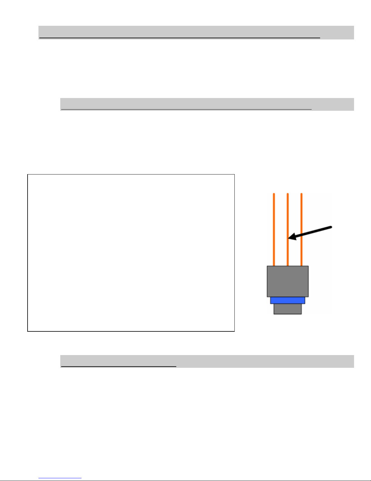
Use the supplied scotk-lok and connect to Pin # 2 or the center wire. With the scotk-lok
connected, then connect the green wire with the male spade connector from the wiring
harness to it.
Auxiliary Fuel Pressure
First you will need to install the supplied banjo bolt and the new sealing washers into the
intake of either the VP44 or CP3. Make sure that you install it into the supply line (larger
line) and not the return line (smaller line). Once the banjo is installed you can install the
fuel pressure sender into the banjo bolt. The thread is 1/8NPT so you will want to snug
the connection up otherwise it will leak. We advise against using Teflon tap as it there is
no filter between this connection and your injection pump. Once this connection is made
you can then attach the ring terminal/yellow wire of the harness.
BD Engine Brake Inc
A10 – 33733 King Rd, Abbotsford, BC, Canada V2S 7M9
Ship: #88 – 446 Harrison St, Sumas, WA 98295 Mail: PO Box 231, Sumas, WA 98295
Ph: 604.853.6096 Fax: 604.853.8749 Internet: www.bd-power.com
Page 18
19 November 2008 BD X-Monitor 2 # 1080500 18
Wiring Diagram (Fuel Pressure)
A10 – 33733 King Rd, Abbotsford, BC, Canada V2S 7M9
Ship: #88 – 446 Harrison St, Sumas, WA 98295 Mail: PO Box 231, Sumas, WA 98295
Ph: 604.853.6096 Fax: 604.853.8749 Internet: www.bd-power.com
BD Engine Brake Inc
Page 19

19 November 2008 BD X-Monitor 2 # 1080500 19
Ford 1999-2003 7.3L
1. Find the lead wire. This is a 2 wire harness with an orange and black wire. The
larger connector needs to be connected to the thermocouple.
2. Route the lead wire from the thermocouple to the driver’s side firewall. There is a
plastic plug that is diamond shaped on the firewall. Pop the plug out from the inside.
You can either leave the entire plug out or drill a hole large enough to fit the lead
wire plug and the plug from harness #1 into the cab. Tie the lead wire out of the
way of any moving or hot parts to avoid damage to the wires.
3. Plug the small 2-wire plug into the corresponding plug on the cable harness.
4. Lay wiring harness #1 out on your engine. The green plug will go inside the cab
using the same location you routed the lead wire through.
5. Locate the engine’s MAP sensor. This is on the passenger side of the engine,
beside the hot side of the intercooler tube. It has 3 wires coming from it.
6. Connect the supplied wire tap to the wire in the middle of the connector. If you have
a power module installed you will need to connect to the same wire on the module’s
A10 – 33733 King Rd, Abbotsford, BC, Canada V2S 7M9
Ship: #88 – 446 Harrison St, Sumas, WA 98295 Mail: PO Box 231, Sumas, WA 98295
Ph: 604.853.6096 Fax: 604.853.8749 Internet: www.bd-power.com
BD Engine Brake Inc
Page 20

19 November 2008 BD X-Monitor 2 # 1080500 20
wiring harness to receive an accurate reading. Only tap the wire of the plug that is
going to the sensor. Tapping the factory wire when using a power module will result
in a false reading.
7. Connect the blue wire to the wire tap.
8. Locate the Engine Oil Temperature Sensor (EOT) towards the front of the engine.
This is a 2-wire connector located on the top of the engine just behind the High
Pressure Oil reservoir. The sensor will be mounted horizontal to the truck. Note: On
the 7.3L engines we monitor the oil
temperature instead of coolant
temperature. This will cause the
temperatures to be slightly higher than
water and you should adjust your
warnings and warm-up module
accordingly.
9. Connect the supplied wire tap to pin
#2. If you are holding the connector
with the clip release facing up and
looking at the back side where the wires enter the connector, then the correct wire
should be on the left side.
10. Connect the orange wire to the wire tap.
Locate the high pressure test port on your transmission. This port is on the driver’s
11.
side of the vehicle. There is a
small plug in the test port.
Remove the plug.
12. Using Teflon tape, screw the
temperature probe and fittings into
the test port. Do not over tighten.
13. Route the purple wire from the
wiring harness to the temperature
sensor.
14. Remove the nut and washers from the sensor and install the purple wire. Replace
the washers and tighten the nut to secure the wire.
15. Go over the wiring harness and secure it to the vehicle out of harms way using the
supplied wire ties. Keep all wires far away from any moving or hot parts.
BD Engine Brake Inc
A10 – 33733 King Rd, Abbotsford, BC, Canada V2S 7M9
Ship: #88 – 446 Harrison St, Sumas, WA 98295 Mail: PO Box 231, Sumas, WA 98295
Ph: 604.853.6096 Fax: 604.853.8749 Internet: www.bd-power.com
Page 21

19 November 2008 BD X-Monitor 2 # 1080500 21
16. Slide the green plug through the rubber grommet where you ran the lead wire. Pull
enough of the wire harness inside the cab so that the switch port connection (white
and black wires), the black wire with the ring terminal, and the red wire with the fuse
tap are inside the cab.
17. Find the bolt located by the firewall and remove it. Place the bolt through the ring
terminal of the black wire and screw it back into its location.
18. Open the fuse box located on the driver’s side below the steering wheel. You will
need to remove the dash panel to access the fuse box.
19. Remove fuse #27 and install the fuse tap over the leg of the fuse. Re-install the
fuse.
20. Once everything is secure and installed, you will want to start your engine. The X2
comes pre-set for these 4 parameters. To make sure everything is installed
correctly, use these basic guidelines:
EGT temperatures should be in the 250-350°F (120-175°C) ranges, depending on
engine temperature and outside temperature. Boost pressure should read 0psi at
idle and up to 5psi while revving the engine at idle. ECT should be similar to your
factory gauge. If the vehicle is cold, it should read close to ambient temperature
and slowly rise.
Transmission temperature will most likely read ~100°F (35°C). It can take up to 20
miles, depending on the outside temperature, driving style and load to reach
temperatures above 100°F (35°C). Operating temperatures range from 110-180°F
(40-80°C) dependant upon load and driving style.
21. Using the supplied wire ties, tie up the wire and cable harness up under the dash.
A10 – 33733 King Rd, Abbotsford, BC, Canada V2S 7M9
Ship: #88 – 446 Harrison St, Sumas, WA 98295 Mail: PO Box 231, Sumas, WA 98295
Ph: 604.853.6096 Fax: 604.853.8749 Internet: www.bd-power.com
BD Engine Brake Inc
Page 22

19 November 2008 BD X-Monitor 2 # 1080500 22
Ford 2003-2006 6.0L
1. Find the lead wire. This is a 2-wire harness with an orange and black wire. The
larger connector needs to be connected to the thermocouple.
2. Route the lead wire from the thermocouple to the driver’s side firewall. There is a
plastic plug that is diamond shaped on the firewall. Some trucks have foil tape that
has to be removed for access through the firewall instead of the plastic plug. From
the inside, pop the plug out. You can either leave the entire plug out or drill a hole
large enough to fit the lead wire plug and the plug from harness #1 into the cab. Tie
the lead wire out of the way of any moving or hot parts to avoid damage to the
wires.
3. Plug the small 2-wire plug into the corresponding plug on the cable harness.
4. Lay wiring harness #1 out on your engine. The green plug will go inside the cabin
using the same location you routed the lead wire through.
5. Locate the engine’s MAP sensor. This is on the passenger side of the engine, next
to the hot side of the intercooler tube. It has 3 wires coming from it.
A10 – 33733 King Rd, Abbotsford, BC, Canada V2S 7M9
Ship: #88 – 446 Harrison St, Sumas, WA 98295 Mail: PO Box 231, Sumas, WA 98295
Ph: 604.853.6096 Fax: 604.853.8749 Internet: www.bd-power.com
BD Engine Brake Inc
Page 23

19 November 2008 BD X-Monitor 2 # 1080500 23
6. Connect the supplied wire tap to the wire in the middle of the connector. IF you
have a power module installed, you will need to connect to the same wire on the
module’s wiring harness to receive an accurate reading. Only tap the wire of the
plug that is going into the sensor. Tapping the factory wire when using a power
module will result in a false reading.
7. Connect the blue wire to the wire tap.
8. Locate the Engine Coolant Temperature Sensor
(ECT) on the front of the engine, just below the
upper radiator hose. This is a 2-wire, gray
connector.
9. Connect the supplied wire tap to pin #2. If you
are holding the connector with the clip release
facing up and looking at the back side where the
wires enter the connector, the correct wire should be on the left side.
10. Connect the orange wire to the wire
tap.
11.
Locate the high pressure test port
on your transmission. This port is
on the driver’s side of the vehicle.
There is a small plug in the test
port. Remove the plug.
12. Using Teflon tape, screw the
temperature probe and fittings into
the test port. Do not over-tighten.
13. Route the purple wire from the wiring harness to the temperature sensor.
14.
Remove the nut and washers from the sensor and install the purple wire. Replace
the washers and tighten the nut to secure the wire.
15. Go over the wiring harness and secure it to the vehicle (out of harms way) using the
supplied wire ties. Keep all wires as far away from hot or moving engine parts as
possible.
16. Slide the green plug through the rubber grommet where you ran the lead wire. Pull
enough of the wire harness inside the cab so that the switch port connection (white
and black wires), the black wire with the ring terminal, and the red wire with the fuse
tap are inside the cab.
BD Engine Brake Inc
A10 – 33733 King Rd, Abbotsford, BC, Canada V2S 7M9
Ship: #88 – 446 Harrison St, Sumas, WA 98295 Mail: PO Box 231, Sumas, WA 98295
Ph: 604.853.6096 Fax: 604.853.8749 Internet: www.bd-power.com
Page 24

19 November 2008 BD X-Monitor 2 # 1080500 24
17. Find the bolt located by the firewall and remove it. Place the bolt through the ring
terminal of the black wire and screw it back into its original location.
18. Open the fuse box, located on the driver’s side below the steering wheel. You will
need to remove the dash panel to access the fuse box.
19. Remove fuse #45 and install the fuse tap over the leg of the fuse, and then reinstall the fuse.
20. Once everything is secure and installed, you will want to start your engine. The X2
comes pre-set for these 4 parameters. To make sure everything is installed
correctly, use these basic guidelines:
EGT temperatures should be in the 250-350°F (120-175°C) ranges, depending on
engine temperature and outside temperature. Boost pressure should read 0psi at
idle and up to 5psi while revving the engine at idle. ECT should be similar to your
factory gauge. If the vehicle is cold, it should read close to ambient temperature
and slowly rise.
Transmission temperature will most likely read ~100°F (35°C). It can take up to 20
miles, depending on the outside temperature, driving style and load to reach
temperatures above 100°F (35°C). Operating temperatures range from 110-180°F
(40-80°C) dependant upon load and driving style.
21. Using the supplied wire ties, tie up the wire and cable harness under the dash.
A10 – 33733 King Rd, Abbotsford, BC, Canada V2S 7M9
Ship: #88 – 446 Harrison St, Sumas, WA 98295 Mail: PO Box 231, Sumas, WA 98295
Ph: 604.853.6096 Fax: 604.853.8749 Internet: www.bd-power.com
BD Engine Brake Inc
Page 25

19 November 2008 BD X-Monitor 2 # 1080500 25
Duramax 2001-06
1. Find the lead wire. This is a 2-wire harness with an orange and black wire. The
larger connector needs to be connected to the thermocouple.
2. Route the lead wire across the engine bay to the driver’s side. Tie the lead wire out
of the way of any moving or hot parts to avoid damage to the wires.
3. On the driver’s side firewall, there is a rubber plug. Cut a slit in the outer portion of
the plug to route the small connector and wire into the cab.
4. Plug the small 2-wire plug into the corresponding plug on the cable harness.
5. Lay wiring harness #1 out on your engine. The green plug will go inside the cabin
using the same location you routed the
lead wire through.
Locate the main engine plugs. These
are located on the driver’s side of the
engine, directly above the valve cover.
There are 2 large connectors stacked
on top of each other. You are looking
for the smaller plug that is on the top.
This is a 24-pin connector. Connect
the supplied wire tap to pin “C8”. This
should be a light green wire located in
the top row of wires and nearest to the
firewall.
6. Connect the blue wire from your X2 to
the blue wire tap.
If you have an aftermarket transmission pan you may now install the 1/8” NPT
sensor into the oil pan fitting. On factory transmission there is also a test port
located on the bottom and towards the front of the transmission. You may desire to
get the proper “AN” fitting to take a reading at this location, but it is not
recommended due to the fact that the sensor could be damaged from protruding
too low off of the transmission. We recommend using the 1/8” NPT probe to
measure oil temperature on the Duramax engines.
7. Find the 3/8” x 1/8” NPT bushing included with your kit.
8. Using Teflon tape, install the temperature probe into the bushing.
A10 – 33733 King Rd, Abbotsford, BC, Canada V2S 7M9
Ship: #88 – 446 Harrison St, Sumas, WA 98295 Mail: PO Box 231, Sumas, WA 98295
Ph: 604.853.6096 Fax: 604.853.8749 Internet: www.bd-power.com
BD Engine Brake Inc
Page 26

19 November 2008 BD X-Monitor 2 # 1080500 26
9. Locate the oil filter housing. This
is easiest to find from under the
driver’s side of the engine. On
the oil filter housing, look for the
3/8” bushing that uses an 8mm
hex head for removal. This port
should be located towards the
front of the housing and should
be facing the driver’s side front
tire. Have a rag ready as you will
spill some oil. Make sure that the
vehicle has cooled off as the oil
can be very hot.
10. Using Teflon tape, install the
bushing into the port. Be careful not to over-tighten it.
11. Route the purple wire from the X2 wiring harness to the temperature sensor.
Remove the nut and washers from the sensor and install the purple wire.
12.
Replace the washers and nut onto the temperature sensor. Make sure that the nut
is secure but do not over-tighten it.
13. Go over the wiring harness and secure it to the vehicle (out of harms way) using the
supplied wire ties. Keep all wires as far away from moving or hot parts of the engine
as possible.
14. Slide the green plug through the rubber grommet where you ran the lead wire. Pull
enough of the wire harness inside the cab so that the switch port connection (white
and black wires), the black wire with the ring terminal and the red wire with the fuse
tap are inside the cab.
15. Find the bolt located by the firewall and remove it. Place the bolt through the ring
terminal of the black wire and screw it back into its location.
16. Open the fuse box located on the inside of the truck on the driver’s side of the dash.
You will be required to open the driver’s side door to access the fuse compartment.
17. Re-install the fuse. Attach the red wire with the fuse tap to the fuse labeled “IGN”
18. Once everything is secure and installed, you will want to start your engine. The X2
comes pre-set for these 4 parameters. To make sure everything is installed
correctly, use these basic guidelines:
BD Engine Brake Inc
A10 – 33733 King Rd, Abbotsford, BC, Canada V2S 7M9
Ship: #88 – 446 Harrison St, Sumas, WA 98295 Mail: PO Box 231, Sumas, WA 98295
Ph: 604.853.6096 Fax: 604.853.8749 Internet: www.bd-power.com
Page 27

19 November 2008 BD X-Monitor 2 # 1080500 27
EGT temperatures should be in the 250-350°F (120-175°C) ranges, depending on
engine temperature and outside temperature. Boost pressure should read 0psi at
idle and up to 5psi while revving the engine at idle. ECT should be similar to your
factory gauge. If the vehicle is cold, it should read close to ambient temperature
and slowly rise.
Transmission temperature will most likely read ~100°F (35°C). It can take up to 20
miles, depending on the outside temperature, driving style and load to reach
temperatures above 100°F (35°C). Operating temperatures range from 110-180°F
(40-80°C) dependant upon load and driving style.
NOTE: Coolant temperature on 01-06 Duramax’s is not currently supported.
This may be a feature that will be available with a future update available via
the web.
19. Using the supplied wire ties, tie up the wire and cable harness under the dash.
A10 – 33733 King Rd, Abbotsford, BC, Canada V2S 7M9
Ship: #88 – 446 Harrison St, Sumas, WA 98295 Mail: PO Box 231, Sumas, WA 98295
Ph: 604.853.6096 Fax: 604.853.8749 Internet: www.bd-power.com
BD Engine Brake Inc
Page 28

19 November 2008 BD X-Monitor 2 # 1080500 28
Universal Wiring Diagram
A10 – 33733 King Rd, Abbotsford, BC, Canada V2S 7M9
Ship: #88 – 446 Harrison St, Sumas, WA 98295 Mail: PO Box 231, Sumas, WA 98295
Ph: 604.853.6096 Fax: 604.853.8749 Internet: www.bd-power.com
BD Engine Brake Inc
Page 29
19 November 2008 BD X-Monitor 2 # 1080500 29
Display Functions
The X2 has 4 buttons for control. The buttons have a reference on the display screen for
ease of use.
The top button is the Menu/Escape button. This button can be used to enter the Main
Menu anytime you have the X2 in the monitoring mode. Simply press the top button once
and you will enter the Main Menu.
The top button is also the Escape (back) button. Once you are in the main menu you can
press the top button again to go back to the main display. While in any other menu, this
button will bring you back one menu level. You can use this button to completely escape
from the menus if you desire.
The 2
a button to scroll rapidly through any menu. These buttons are also used for adjusting
power levels up and down if the X2 is connected to a module/chip.
The bottom button is the Select button. Use this button to choose your options in the
menu. This button will advance you to the next menu or screen.
The X2 uses a highlighted cursor so that you can easily navigate the menu. The selection
that the cursor is over will be in black and the numbers/letters will appear in white.
The X2 defaults to a 4-function display upon initial startup. EGT/Boost PSI/ Transmission
Temp and Coolant Temp will be displayed. The power level will be defaulted at 0. Defueling and all warnings will be turned to the off position.
nd
and 3rd buttons are used to move up and down in the menus. You may also hold
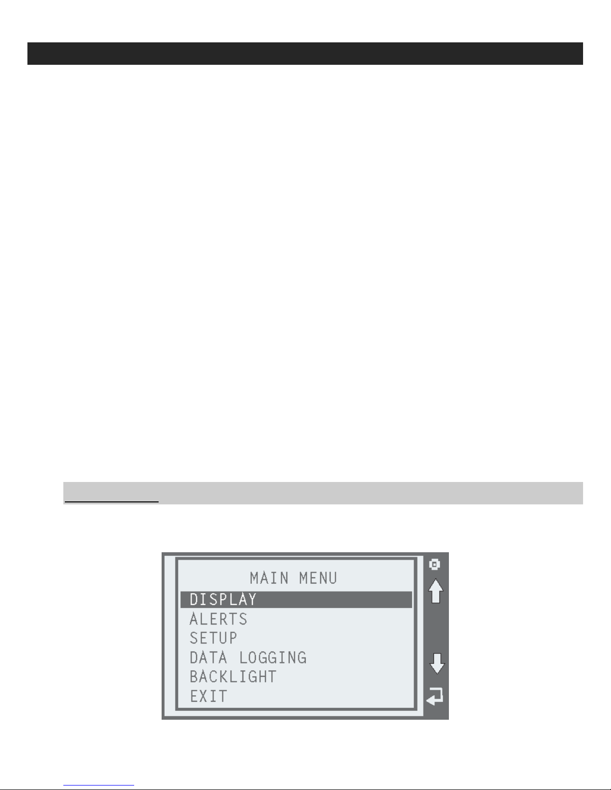
Main Menu
To get to the main menu, press the top or menu button one time. You will see the
following menu:
BD Engine Brake Inc
A10 – 33733 King Rd, Abbotsford, BC, Canada V2S 7M9
Ship: #88 – 446 Harrison St, Sumas, WA 98295 Mail: PO Box 231, Sumas, WA 98295
Ph: 604.853.6096 Fax: 604.853.8749 Internet: www.bd-power.com
Page 30
19 November 2008 BD X-Monitor 2 # 1080500 30
Display Menu
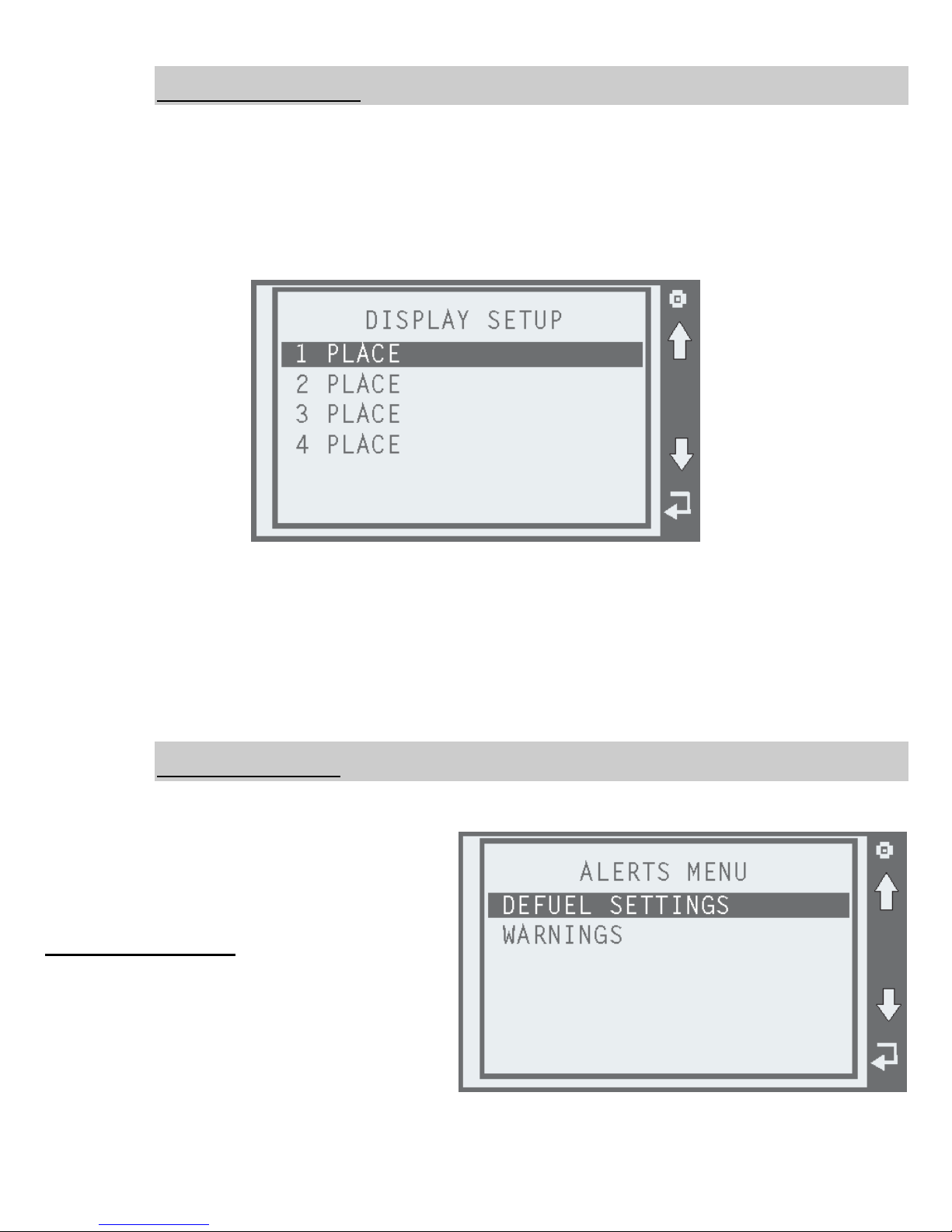
The X2 has 4 different display options. Depending on how many parameters you choose
to view at one time will determine the correct layout for you. Below are examples of all 4
display options. Once you select your desired number of functions to view, you will be
able to customize that view to your liking.
Selection the display menu will show you the following screen:
Selecting any of the above options will allow you to set up how you display the monitored
parameters. A check mark will show you which parameters you have already selected.
Once you make your selection, you will be returned to the main menu. You may move to
another area of the menu or you may choose the exit button. You may also just use the
Esc/Back button if you desire. The X2 will save any changes you make.
Alerts Menu
The alerts menu is where you can set up engine de-fueling if you have a module or chip,
or you may set warnings.
You will see this menu if you select
alerts:
Defueling Settings
Selecting the defuel setting will show you
all of the parameters that you may defuel your engine on as long as they are
monitored. You may select one or all of
the parameters to defuel your engine on,
but it is recommended to be practical in
your selections. The defuel function is meant for safety under normal driving and towing
A10 – 33733 King Rd, Abbotsford, BC, Canada V2S 7M9
Ship: #88 – 446 Harrison St, Sumas, WA 98295 Mail: PO Box 231, Sumas, WA 98295
Ph: 604.853.6096 Fax: 604.853.8749 Internet: www.bd-power.com
BD Engine Brake Inc
Page 31
19 November 2008 BD X-Monitor 2 # 1080500 31
conditions. Selecting values that will be reached on a normal basis will affect drivability as
the truck will constantly be defueling. If you are drag racing it is recommended to turn the
defuel settings to OFF. The defuel settings will be functional even if you choose not to
view the parameter.
Example: If you choose a 1 function display for EGT, but you want to defuel based on
boost, the X2 will display EGT at all times, but it will defuel the engine when the boost
level reaches your set maximum. The X2 will return the full amount of power that you
have selected once the parameter that was exceeded is back within a normal operation
range.
Warnings
Once you enter the warnings menu, you will be able to set a visible warning to any
monitored parameter. You do not have to be viewing the parameter in order for it to give
a warning. You may set as many warnings as you desire. Once again, it is recommended
to keep your warnings practical as constant warnings flashing on your screen may
become undesirable. The X2 has the ability ti display as many as 4 different warnings at
one time.
If one warning is reached, then the X2 will switch to a 1 function display, and display the
parameter that has reached the maximum. If two warnings are reached, the X2 will show
the 2 function display with a warning on each side. The 3 and 4 function screens will
appear if 3 or 4 warnings are reached. The X2 will continue to display the warnings until
the parameters fall back below your set maximum, or you can reset the warnings.
Once again, it is not necessary to view any of the parameters that you choose to set
warnings for. The warnings are meant for parameters that you choose not to watch and
that you want the X2 to watch for you. This gives you the ability to view only those
parameters that you desire to see all the time.
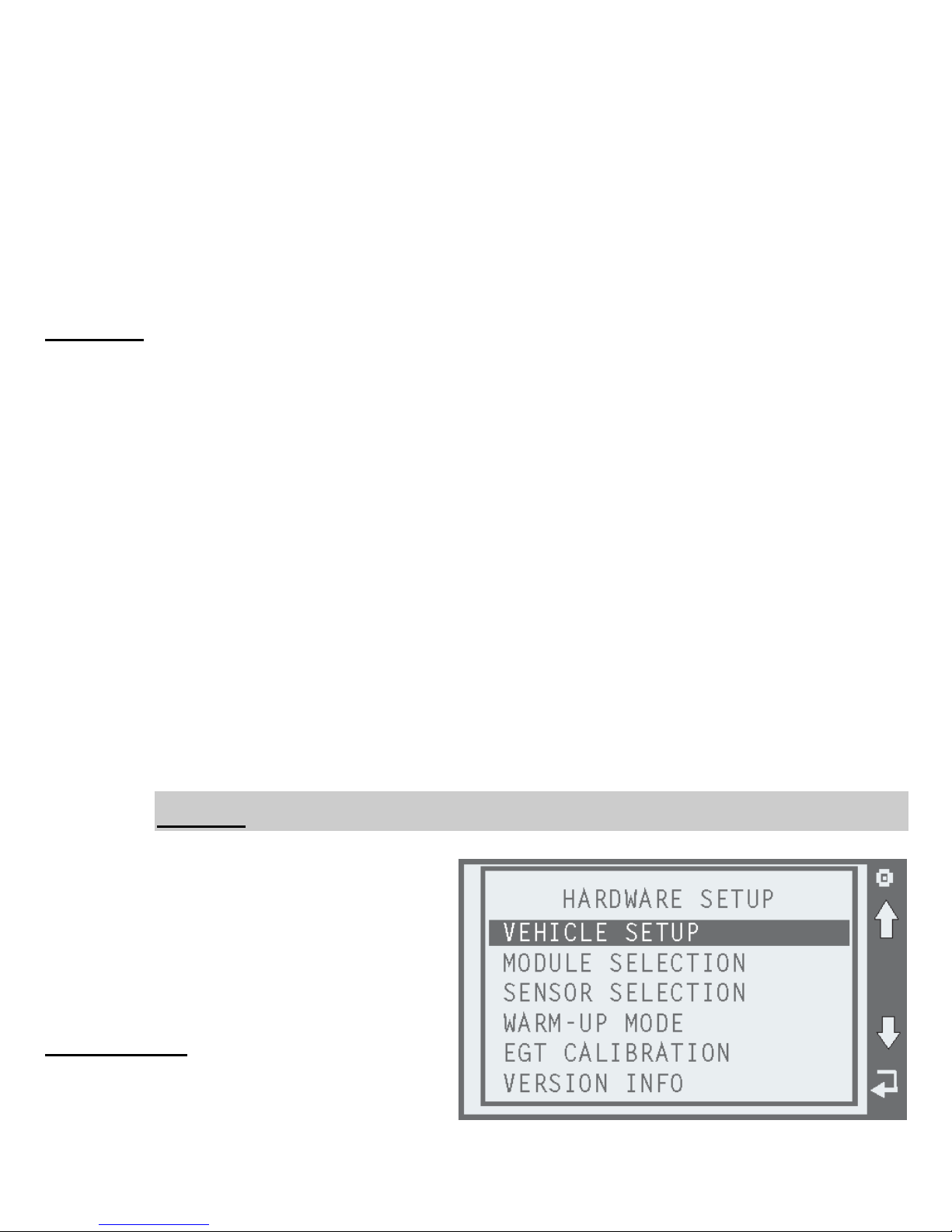
Setup
This menu allows you to select your particular vehicle, choose a power module or chip to
control, turn sensors on and off, set
warm-up mode, calibrate your EGT
gauge, or retrieve version and serial
numbers.
The setup menu is as follows:
Vehicle Setup
This menu allows you to choose what
vehicle you are installing the X2 in. If you
choose to move it to another vehicle, you
BD Engine Brake Inc
A10 – 33733 King Rd, Abbotsford, BC, Canada V2S 7M9
Ship: #88 – 446 Harrison St, Sumas, WA 98295 Mail: PO Box 231, Sumas, WA 98295
Ph: 604.853.6096 Fax: 604.853.8749 Internet: www.bd-power.com
Page 32

19 November 2008 BD X-Monitor 2 # 1080500 32
may switch vehicles at any time. It is important to select the proper vehicle as the proper
data is needed for coolant and boost monitoring.
Module Selection
This provides the list of the supported power modules and chips that you can control.
Some modules and chips are not supported on the standard version of the X2 and may
require additional hardware.
Sensor Selection
This section allows you to turn parameters on or off. If you choose to view a parameter
that is turned off, the X2 will display OFF in the corresponding window that it is to be
viewed in. If you are connected to this parameter and choose to monitor it you must turn
it to ON.
Warm-Up Mode
The Warm-Up Mode is only for vehicles using a module or chip. This allows you to
choose what temperature your module or chip starts adding power. The X2 will turn the
power adder to the last used power level. The default is at zero. This works for any
module or chip that the X2 is controlling. If your module already has cold engine
protection you can turn this off, or you may want to raise the temperature at which it
starts adding power. The X2 will supersede the module’s set warm-up temperature as
long as the turn-on point is higher than the module’s.
EGT Calibration
This function allows you to slightly alter the EGT reading of your gauge. If you already
have an analog gauge that you trust, you want to use an existing thermocouple, or you
have a thermocouple test tool, you may dial the X2 in to read exactly like your existing
gauge. The amount of scaling is not large and is used for fine tuning if you desire. The X2
comes set to match perfectly with the supplied thermocouple and should only be altered if
you have the proper equipment.
Version Info
This is where you may retrieve your software version number as well as the
Commander’s serial number. This is very helpful information if technical assistance is
ever needed. The version number will also be needed in order to download updates to
the X2.
Data Logging
This is where your records are stored. The X2 keeps a log of all minimum and maximum
values it records from the time you start your truck. Each time you turn your vehicle off,
the X2 resets the log and starts a new one. If you desire to reset your parameters while
the vehicle is running you may do so by selecting RESET ALL.
A10 – 33733 King Rd, Abbotsford, BC, Canada V2S 7M9
Ship: #88 – 446 Harrison St, Sumas, WA 98295 Mail: PO Box 231, Sumas, WA 98295
Ph: 604.853.6096 Fax: 604.853.8749 Internet: www.bd-power.com
BD Engine Brake Inc
Page 33

19 November 2008 BD X-Monitor 2 # 1080500 33
To retrieve the logged data, simply select the RECORDS item, and then select the
desired parameter.
Backlight
The X2 is equipped with a fully adjustable backlight. By selecting the backlight menu you
will be able to dim or brighten the backlight to suit your viewing needs.
Technical Support
If you require technical support for this product, please call our Technical Support hotline
at (800) 887-5030 between 8am – 5pm, Monday to Friday, Pacific Standard Time (PST).
You can also post a technical support question on the BD Power Forums, located at
http://www.bd-power.com/forum/
A10 – 33733 King Rd, Abbotsford, BC, Canada V2S 7M9
Ship: #88 – 446 Harrison St, Sumas, WA 98295 Mail: PO Box 231, Sumas, WA 98295
Ph: 604.853.6096 Fax: 604.853.8749 Internet: www.bd-power.com
BD Engine Brake Inc
Page 34

19 November 2008 BD X-Monitor 2 # 1080500 34
LIMITED WARRANTY STATEMENT
BD Engine Brake, Inc., Valley Fuel Injection Ltd., BD Diesel Performance, Turbocharger.net (the “Seller”)
warrants the following product(s):
All products manufactured or rebuilt by the Seller are to be free from defects in material or workmanship which
includes but is not limited to Turbochargers, Exhaust and Intake manifolds, Exhaust brakes, Intercoolers, Flex
Plates, Transmissions, Torque Converters, Oil pans, Fuel pumps and systems, Electronic monitors and control
systems. The Seller warrants to the original buyer of the product (the “Buyer”) that it will repair or replace, free of
charge, any product which has a defect in material or workmanship within the warranty period described below.
Copy of original invoice is required to qualify for warranty.
A defect is defined as a condition within the product that would render the product inoperable under normal
conditions of use and service. The Seller’s responsibility under this Warranty is limited to the repair or
replacement, at the Seller’s option, of any warrantable product returned prepaid with a complete service history
and proof of purchase. A valid proof of purchase is a dated bill of sale or receipt.
A Return Material Authorization (RMA) number, obtained in advance from a customer service representative of
the Seller and the dated bill of sale or receipt, must accompany any product returned by the Buyer for warranty
determination. The Seller will be the final authority on the approval of all warranty claims hereunder. The
issuance of a RMA number does not represent an approval of a warranty claim. All repaired or replaced products
will be returned to the Buyer freight collect. Accepted warranty products, which have been replaced, will become
the sole property of the Seller.
Until the Seller has approved a warranty claim, the Buyer will be responsible for all costs. Replacement parts and
the labor costs incurred by the removal and replacement of the product while performing warranty work will be the
responsibility of the Buyer. In no case does the obligation of the Seller exceed the original purchase price of the
product as indicated on the original bill of sale or receipt. Under no circumstances will the Seller be liable for any
travel time incurred in diagnosis for defects, or any other contingent expenses.
Once the claim is approved and with in a 1 year period of original purchase Labor costs incurred will be
considered for the removal and replacement of an eligible part while performing warranty work, at a rate of 55.00
per hour at authorized centers with prior approval of the Seller. Freight is FOB Abbotsford, B.C. Canada.
To the extent permitted by law, the Buyer hereby waives all rights other than those expressly set out herein and
acknowledges that this warranty sets out the Buyer’s exclusive remedies with respect to products covered by it.
This warranty shall not be extended, amended or varied except by written instrument signed by the Seller and the
Buyer.
The Seller will administer warranty requests on products sold by the Seller and not manufactured by the Seller by
forwarding claims made by a Buyer under the manufacturer’s warranty to the manufacturer. The final disposition
of such claims will be made by the manufacturer and ruled by the laws of British Columbia, Canada.
Customer assumes risk in purchasing product with in 30 days may return the product for exchange of other BD
products or services only. No cash refunds are available.
Please refer to Warranty time limitation per product.
A10 – 33733 King Rd, Abbotsford, BC, Canada V2S 7M9
Ship: #88 – 446 Harrison St, Sumas, WA 98295 Mail: PO Box 231, Sumas, WA 98295
Ph: 604.853.6096 Fax: 604.853.8749 Internet: www.bd-power.com
BD Engine Brake Inc
Page 35

19 November 2008 BD X-Monitor 2 # 1080500 35
NOT COVERED UNDER THIS WARRANTY
This warranty is limited to the original purchaser of the product and is not transferable to subsequent owners.
Specifically excluded from this warranty are failures of products caused by misuse, misapplication, negligence of
the Buyer, accidents, modification, abuse, improper storage, installation, repair or operation, use of unauthorized
parts or other mistreatment of the Buyer or his agent. Any competitive use, sled pulling, drag racing will void
warranty on product. A sheared or twisted shaft, broken planetary gear sets, burned clutches, broken drive hubs,
sun gear damage, cracked housings is not covered. Fluids and filters or damage caused from fuel or air
contamination, BioDiesel, low fluid levels. This warranty does not cover deterioration of plating, paint or any other
coating, linings or parts that are subject to normal wear and tear, such as light bulbs, fuses, bearing wear, seal
wear, etc.
If product is not installed by a trained and authorized BD dealer, installation facility must prove it is properly tooled
and has certified training to have installed or to carry out repair of product.
The Seller also disclaims any liability for incidental or consequential damages including but not limited to, repair
labor, rental vehicles, hotel cost or any other inconvenience cost. To the extent permitted by law, this warranty is
in lieu of all other warranties or guaranties, either expressed or implied, included the implied warranties of
merchantability and fitness for a particular purpose and shall not extend to any Buyer or to any person other than
the original purchaser residing within the boundaries of the continental U.S. or Canada. As well the seller is not
responsible or obligated to update previously manufactured parts that are currently under the above warranty.
NOTE THAT THIS GUARANTEE WILL BE VOID IF THE USER BREACHES THE CONDITIONS IN THE
SECTION LABELED “NOT COVERED UNDER THIS WARRANTY” AND IS ONLY APPLICABLE ON THE
PRODUCTS THE SELLER MANUFACTURES.
DISCLAIMER OF LIABILITY
Other than as expressly set forth herein, the Seller, together with its distributors, jobbers and dealers shall in no
way be responsible for the product’s proper use and service. In no event shall the Seller be liable for any special,
incidental, indirect or consequential damages of any kind or nature, whether or not the Buyer was advised of the
possibility of damage, arising or resulting from the use or performance of the product, and the Buyer hereby
waives any and all such claims.
The Buyer acknowledges that he/she/it is not relying on the Seller’s skill or judgment to select or furnish goods
suitable for any particular purpose and that the Seller has no liability that will extend beyond the scope of the
limited warranty contained herein, and the Buyer hereby waives all remedies or liabilities, expressed or implied,
arising by operation of law or otherwise, (including, without limitation, any obligations of the Seller with respect to
fitness for any particular purpose; merchantability; and special, incidental, indirect or consequential damages) or
whether or not occasioned by the Seller’s negligence.
The Seller disclaims any warranty and expressly disclaims any liability for personal injury or damages related to
the Buyer’s use of the product. The Buyer acknowledges and agrees that the disclaimer of any liability for
personal injury is a material term for this Agreement and the Buyer agrees to indemnify the Seller and hold the
Seller harmless from any claim related to the product and its use or performance. Under no circumstances will
the Seller be liable for any damages, liabilities, costs or expenses incurred as a result of by reason of the use,
performance or sale of the product, including without limitation, any damages, liabilities, costs or expenses
incurred by reason of the Buyer’s negligence related to those uses of the product as a result of the removal of the
speed limiter.
The Seller assumes no liability regarding the improper installation or misapplication of the product. It is the
installer’s responsibility to check for proper installation, and, if in doubt, contact the manufacturer.
A10 – 33733 King Rd, Abbotsford, BC, Canada V2S 7M9
Ship: #88 – 446 Harrison St, Sumas, WA 98295 Mail: PO Box 231, Sumas, WA 98295
Ph: 604.853.6096 Fax: 604.853.8749 Internet: www.bd-power.com
BD Engine Brake Inc
Page 36
19 November 2008 BD X-Monitor 2 # 1080500 36
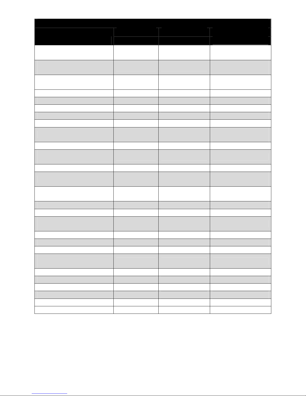
Limited Warranty Details
Parts Labour
Product Name
(Months/Miles)
1
(Months/Miles)
Torque Converters (Dodge) 36/ 150,000 12/12,000
Torque Converters (Ford &
Allison)
36/ 150,000 12/ 12,000
Transmissions 36/ 150,000 12/ 24,000
Race Transmissions 12/ 24,000 Not Eligible
Valve / Accumulators Bodies 12/ 24,000 12/ 24,000
Transmission Pans 36/ 150,000 Not Eligible
Auto / Torq / Towloc’s 12 / 24,000 Not Eligible
Flex Plates 36/ 150,000 Not Eligible
Injectors & Injection Pumps 12 / 24,000 12/ 24,000
Tuners and Chips Manufacturer3 Not Eligible
X-Monitor / Cool Down
Timers
12/ 24,000 Not Eligible
Intake / Exhaust Manifolds 36/ 75,000 Not Eligible
Exhaust Kits 24 Months Not Eligible
Turbo Guards / Boost
Builders / Waste Gate Kits
12/ 24,000 Not Eligible
Intercoolers / Hoses / Clamps 12/ 24,000 Not Eligible
Transmission Coolers Manufacturer3 Manufacturer3
Manual Transmission
Clutches
Manufacturer3 Manufacturer3
Short Shifters 12/ 24,000 Not Eligible
Engine / Head Stud kits Manufacturer3 Manufacturer3
Engine Brakes 24/ 24,000 12/ 24,000
Steering Stabilizers / Sway
bars
12/ 24,000 Not Eligible
Boost Coolers Manufacturer3 Manufacturer3
Gauges and Mounts Manufacturer3 Manufacturer3
Performance Turbos 12/ 12,000 Not Eligible
FlowMAX Fuel Pumps 60/ 75,000 Not Eligible
Auxiliary Fuel Pumps 12/ 12,000 Not Eligible
1, 2
Notes
No Race abuse
covered
No Race abuse
covered
No Race abuse
covered
Race Pumps 90 days
parts/No labour
Surface rust not
eligible
A Return Material Authorization (RMA) number, obtained in advance from a customer service representative of the Seller and the dated bill of sale or receipt,
must accompany any product returned by the Buyer for warranty determination.
1
Warranty is based on whichever occurs first (Months or Mileage).
2
Prior approvals must be given to qualify for labour reimbursement.
3
As per Manufacturer’s warranty
BD Engine Brake Inc
A10 – 33733 King Rd, Abbotsford, BC, Canada V2S 7M9
Ship: #88 – 446 Harrison St, Sumas, WA 98295 Mail: PO Box 231, Sumas, WA 98295
Ph: 604.853.6096 Fax: 604.853.8749 Internet: www.bd-power.com
 Loading...