

Page 1

BDCOM S6508 Switch
Hardware Installation Guide
Page 2

Content
Table of Content
Chapter 1 Information of BDCOM S6508 Switch..................................................................................................................1
1.1 Overview................................................................................................................................................................1
1.2 Features................................................................................................................................................................1
1.3 S6508 Switch View................................................................................................................................................2
1.4 S6508 Switch Hareware composing......................................................................................................................3
1.4.1 Rack..........................................................................................................................................................3
1.4.2 Chassis......................................................................................................................................................3
1.4.3 System module Slots.................................................................................................................................6
1.4.4 Power Supply............................................................................................................................................7
1.5 S6508 Switch Airflow.............................................................................................................................................9
1.6 S6508 system module overview..........................................................................................................................10
1.6.1 System Management and Switching Unit module (LS6508-MSU).......................................................... 11
1.6.2 4-Ports Gigabit TX/SFP Module(LS65-4GE-TX/SFP).......................................................................13
1.6.3 4-Ports Gigabit SFP Module(LS65-4GE-SFP)..................................................................................15
1.6.4 16-Port 100BASE SFP Module (LS65-16FE-SFP)..........................................................................17
1.6.5 32-Port 10/100BASE-TX Module(LS65-32FE-TX)............................................................................19
Chapter 2 Preparing for installation....................................................................................................................................22
2.1 Safety notice........................................................................................................................................................22
2.1.1 Ensure safety as the following principals................................................................................................22
2.1.2 Safety principal of Moving.......................................................................................................................22
2.1.3 Safety principal of operation with electricity............................................................................................23
2.1.4 Preventing Electrostatic Discharge Damage...........................................................................................23
2.1.5 Laser warning..........................................................................................................................................24
2.2 General site requirements...................................................................................................................................24
2.2.1 Reqirements of the rack..........................................................................................................................24
2.2.2 Air Flow conditions..................................................................................................................................24
2.2.3 Temperature and Humidity......................................................................................................................25
2.2.4 Air Environment.......................................................................................................................................26
2.2.5 Power supply condition...........................................................................................................................27
2.3 System Grounding...............................................................................................................................................27
2.3.1 Grounding Safety....................................................................................................................................27
2.3.2 Lightning protection.................................................................................................................................27
2.3.3 The grounding of EMC............................................................................................................................28
2.3.4 EMI calculation........................................................................................................................................28
2.3.5 Fiber-Optic Connectors Note...................................................................................................................29
2.4 The request of installation tools...........................................................................................................................29
2.5 Requirement of checking.....................................................................................................................................29
2.5.1 Checking Equipment...............................................................................................................................30
2.5.2 Record local log.......................................................................................................................................31
Chapter 3 Installing switch..................................................................................................................................................32
3.1 Installing flow.......................................................................................................................................................32
- I -
Page 3

Content
3.2 Site for installing..................................................................................................................................................33
3.3 Installing Rack.....................................................................................................................................................33
3.3.1 Notice proceeding...................................................................................................................................33
3.3.2 Installing steps.........................................................................................................................................34
3.4 Installing the S6508 chassis in Rack...................................................................................................................34
3.4.1 Notice proceeding...................................................................................................................................34
3.4.2 Installation steps......................................................................................................................................34
3.5 Establishing the system ground...........................................................................................................................34
3.5.1 Notice proceeding...................................................................................................................................35
3.5.2 Grounding Steps.....................................................................................................................................35
3.6 Connecting the DC Power supply........................................................................................................................35
3.6.1 Notice proceeding...................................................................................................................................36
3.6.2 Connecting steps.....................................................................................................................................36
3.7 Connecting the AC Power supply........................................................................................................................36
3.7.1 Notice proceeding...................................................................................................................................37
3.7.2 Connecting steps.....................................................................................................................................37
3.8 Connect the cable to the LS6508-MSU module..................................................................................................37
3.8.1 Connecting steps.....................................................................................................................................37
3.9 Removing the system Module.............................................................................................................................38
3.9.1 Removing steps.......................................................................................................................................38
3.10 Installing the system module.............................................................................................................................39
3.10.1 Installing steps.......................................................................................................................................39
3.11 Connecting external interface cable..................................................................................................................39
3.11.1 Notice proceeding..................................................................................................................................39
3.11.2 Connecting Steps..................................................................................................................................39
3.12 Packing cable....................................................................................................................................................39
3.12.1 Notice proceeding.................................................................................................................................39
3.12.2 Packing Steps.......................................................................................................................................40
3.13 Verifying the Switch chassis Installation............................................................................................................40
3.13.1 Checking the Rack................................................................................................................................40
3.13.2 Checking the connecting.......................................................................................................................40
3.13.3 Checking the Power..............................................................................................................................40
Chapter 4 System debug....................................................................................................................................................41
4.1 Debug flow ..........................................................................................................................................................41
4.2 set up configurable environment.........................................................................................................................41
4.2.1 set up configurable environment by console...........................................................................................41
4.3 Check the status before system operating..........................................................................................................44
4.3.1 Power Check...........................................................................................................................................44
4.4 start system and watch initialization status..........................................................................................................44
4.4.1 start system.............................................................................................................................................44
4.4.2 check version of software and hardware.................................................................................................44
4.4.3 source of S6508 IOS...............................................................................................................................45
4.5 Install and upgrade S6508 IOS...........................................................................................................................45
4.5.1 Installation and upgradation about S6508 system softerware.................................................................45
4.5.2 update configuratation.............................................................................................................................49
4.5.3 Bootrom upgrade.....................................................................................................................................49
- II -
Page 4

Content
4.5.4 upgrade in CLI(command line interface).................................................................................................51
4.6 basic step of configing S6508..............................................................................................................................52
4.7 upload and download configuration file...............................................................................................................53
Chapter 5 S6508 maintenance...........................................................................................................................................54
5.1 S6508’s monitor function.....................................................................................................................................54
5.2 run diagnose function in s6508............................................................................................................................54
5.3 S6508 hardware maintenance.............................................................................................................................54
5.3.1 The system module maintenance...........................................................................................................54
5.3.2 Fan assembly maintenance....................................................................................................................54
5.3.3 power supply maintenance......................................................................................................................55
5.4 remote maintenance............................................................................................................................................55
Chapter 6 Hardware Troubleshooting.................................................................................................................................56
6.1 The universal flow of checking installation trouble..............................................................................................57
6.2 trouble shooting of losting switch password........................................................................................................58
6.3 deal with hardware installation trouble................................................................................................................58
6.3.1 trouble shooting about power supply module..........................................................................................58
6.3.2 trouble shooting about the module installation........................................................................................59
6.4 trouble shooting about software installation........................................................................................................60
Chapter 7 Appendix............................................................................................................................................................61
7.1 Identification,Package,Transport,Stockpile.........................................................................................................61
7.1.1 Identification in product...........................................................................................................................61
7.1.2 Identification in Package.........................................................................................................................61
7.1.3 Produce Area...........................................................................................................................................61
7.1.4 Product Type...........................................................................................................................................61
7.1.5 Wrapper...................................................................................................................................................61
7.1.6 Transport.................................................................................................................................................62
7.1.7 Stockpile..................................................................................................................................................62
7.2 Tools of open and close the package..................................................................................................................63
7.3 Other ...................................................................................................................................................................63
7.3.1 Files in the package................................................................................................................................63
7.3.2 Cables with Equipment............................................................................................................................63
- III -
Page 5

BDCOM S6508 Switch Hardware Installation Guide
Chapter 1 Information of BDCOM S6508 Switch
1.1 Overview
In recent years, the number of Internet user has experienced an explosive growth. The
traditional communication services which are mainly provided through PSTN can not
satisfy the customers, which means that multimedia services, voice, data and video for
example, should be provided. The traditional narrowband access technology can not
meet the needs of the customers, while the broadband access technology will
change people’s life and work dramatically.
Compared with other broadband access methods, such as ADSL or HFC, ether access
can provide broader band with lower cost. IP is the main service of MAN, and
Ethernet is the most direct way to provide IP service. No other particular equipment is
need, which cut down the cost in the process of protocol transformation. Meanwhile,
Ethernet adapts well to the populous communities. That’s why Ethernet is so
commonly used.
So ShangHai Baud Data Communication Co., Ltd. Provide a business ethernet
scheme to support this application for business ISP, BDCOM S6508 is a switch that
can be managned for buseniss ethernet.
S6508 provides user network manage function and mutlilayer switch function, it also
provides high performance in multilayer switch with wire speed, and provides various
charge mode. BDCOM S6508 provides flexibel, high perpormance service for ISP.
S6508 is a switch can provide many module in need.Use different module can be
used multilayer switch, router and boardband accesses server, meanwhile have
managable funciotn and rich QOS characteristics.
S6508 support the following service:
Support Internet boardband accesses.
Solve the big capability data exchange of MAN about inside or among project,
and build net around the project area.
1.2 Features
L2 and L3 switch with wire speed.
Combine advantage that ASIC process with wire speed and NP flexiable into
together.
High reliablity of redundant backup without reboot.
Reasonable switch capacitance and high port density.
Support various accessing method and allow them to run at the same time.
- 1 -
Page 6
BDCOM S6508 Switch Hardware Installation Guide
Uniform user management.
Agile charge method.
User bandwidth and priority control base on RADIUS.
Use standard switch struct, can expand to other non-ethernet module.
1.3 S6508 Switch View
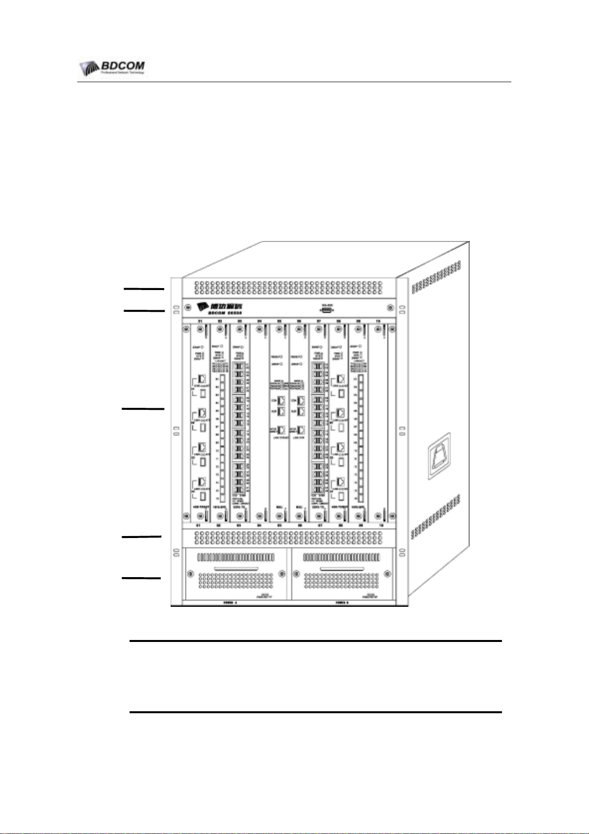
S6508 Switch is a 10-slot vertical chassis. Figure 1-1 shows the S6508 Switch chassis.
(1)
(2)
(3)
(4)
(5)
Figure 1-1 BDCOM S6508 Switch View
(1)Airflow exhaust: the system module air exhaust.
(2)Fan Assembly: the system fan assembly, 6 fans support.
(3)system module slot: 10 system module slots, support 10 system module.
(3)Airflow intake: the system module air inlet.
(4)Power supply slot: support AC-Power module or DC-Power module.
- 2 -
Page 7

BDCOM S6508 Switch Hardware Installation Guide
1.4 S6508 Switch Hareware composing
S6508 Switch Hardware system include Chasssis, Power module and System module.
S6508 Chassis Weight: 35KG; Power module Weight:3.2KG; One System module
Weight: about 2.9KG. Chassis fully configured Weight 68KG(10 modules, 2
AC-Power modules). The final package with the fully configured chassis weight 86KG
(the package weight 17KG; adjunct case weight 1KG).
1.4.1 Rack
S6508 can be installed in
Ltd. can provide 4 type
2.2m metal Rack(H×W×D=2200mm×600mm×600mm)
2.0m metal Rack(H×W×D =2000mm×600mm×600mm)
1.8m metal Rack(H×W×D =1800mm×600mm×600mm)
1.6m metal Rack(H×W×D =1600mm×600mm×600mm)
1.4.2 Chassis
19-inch Rack. ShangHai Baud Data Communication Co.,
standard
19-inch Rack:
The S6508 Chassis is 19 Inchs Chassis, The chassis hight is 670mm(15U), width is
440mm, depth is 455mm. The chassis include Airflow exhaust, Fan assembly, System
module Slots, Airflow intake and Power Supply Slots.
System module Slots are the main of the chassis. The system modules can be pluged
in the Slots.
On the bottom of chassis, there are two Power supply Slots, Between the Power
supply Slots and the System module Slots, there is the airflow intake.
Fan Assembly is on the top of System module Slots. The Fan Assembly have 6 fans.
On the top of Fan Assembly,there is the airflow exhaust.
- 3 -
Page 8
BDCOM S6508 Switch Hardware Installation Guide
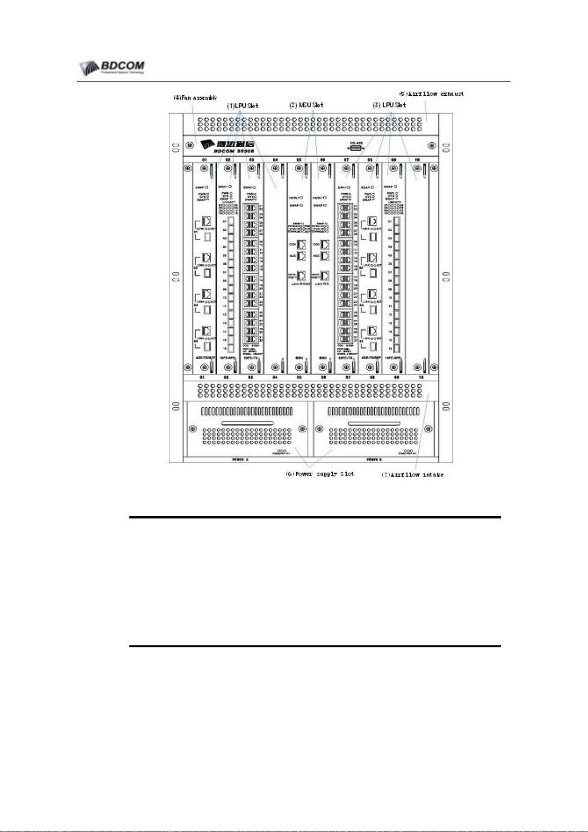
Figure 1-2 S6508 front View
1)LPU slot: there are 8 LPU slots, the LPU module such as LS65-32FE-TX,
(
LS65-4GE-TX/SFP and LS65-16FE-SFP can be pluged in the Slots.
(2)MSU slot:there are 2 MSU slots,only support LS6508-MSU.
(3)LPU slot: there are 8 LPU slots, the LPU module such as LS65-32FE-TX,
LS65-4GE-TX/SFP and LS65-16FE-SFP can be pluged in the Slots.
(4)Fan Assembly: the system fan assembly, 6 fans support.
(5)Airflow exhaust: the system module air exhaust.
(6)Power supply slot: support AC-Power module(800W) or DC-Power
module(800W).
(7)Airflow intake: the system module air inlet.
- 4 -
Page 9
BDCOM S6508 Switch Hardware Installation Guide
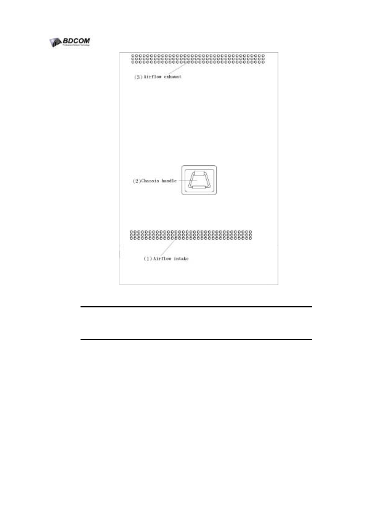
Figure 1-3 S6508 side view
Airflow int ake: the system module air inlet.
(1)
Chassis handle: can be used to move the S6508.
(2)
Airflow exhaust: the system module air exhaust.
(3)
- 5 -
Page 10
BDCOM S6508 Switch Hardware Installation Guide
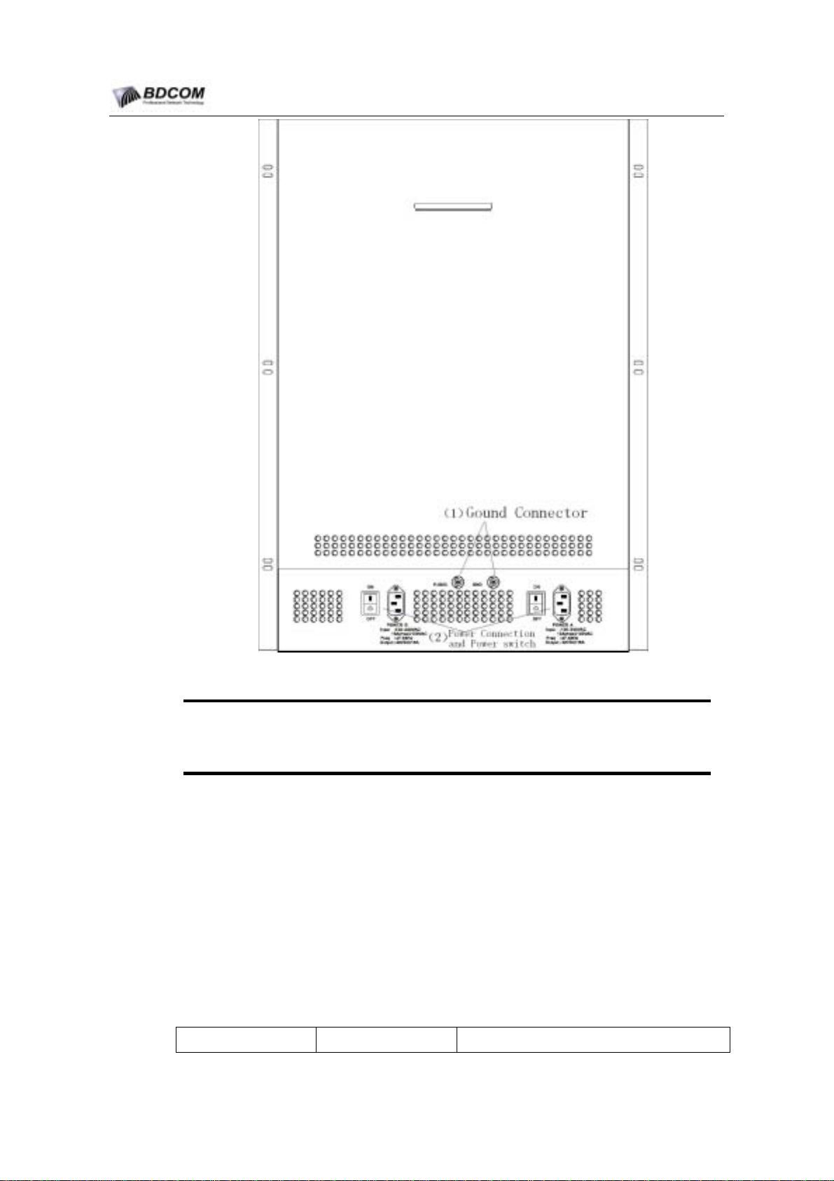
Figure 1-4 S6508 Rear View
Gound Connector: System Gound Connector.
(1)
Power Connection and Power switch: The System Power supply’s Power
(2)
Connection and Power switch.
1.4.3 System module Slots
System module Slots include the slot guides and the backplane.
The S6508 chassis have 10 system module Slots, the space between the two near
Slots is 40mm. The slots is vertical.The Slots number is ordinal, from left to right is Slot
1 to Slot 9. The Slot 5 and the Slot 6 are MSU Slots that only support the LS6508-MSU,
and other modules must not be pluged in. Slot 1-4 and Slot 7-10 are LPU Slots that
support the other S6508 Switching modules.
The following Table1-1 describes the System Slots support module.
Table 1-1 System Slots Sopport module Decription
Slot number Slot Name Support module name
- 6 -
Page 11
BDCOM S6508 Switch Hardware Installation Guide
Slot 1-4 LPU Slot
Slot 5-6 MSU Slot LS6508-MSU
LS65-32FE-TX
LS65-4GE-TX/SFP
LS65-4GE-SFP
LS65-16FE-SFP
Slot 7-10 LPU Slot
The system module’s height is 370mm, depth is 370mm.
1.4.4 Power Supply
S6508 support AC-Power Input or DC-Power Input.There are 2 type Power supply
module(AC-Power supply module and DC-Power supply module ) are supported in
S6508.
1. DC-Power Supply
When you want to use DC Supply input, you can use LS65-PWR-DC-800 module.The
DC-Power input must be –48V. LS65-PWR-DC-800 max output is 800W.
LS65-32FE-TX
LS65-4GE-TX/SFP
LS65-4GE-SFP
LS65-16FE-SFP
2. AC-Power Supply
When you want to use AC-Power input,you can use LS65-PWR-AC-800 module. The
AC-Power input is 100~240V/AC; the AC-Power input frequency is 47Hz
63Hz.LS65-PWR-AC-800 max output is 800W.
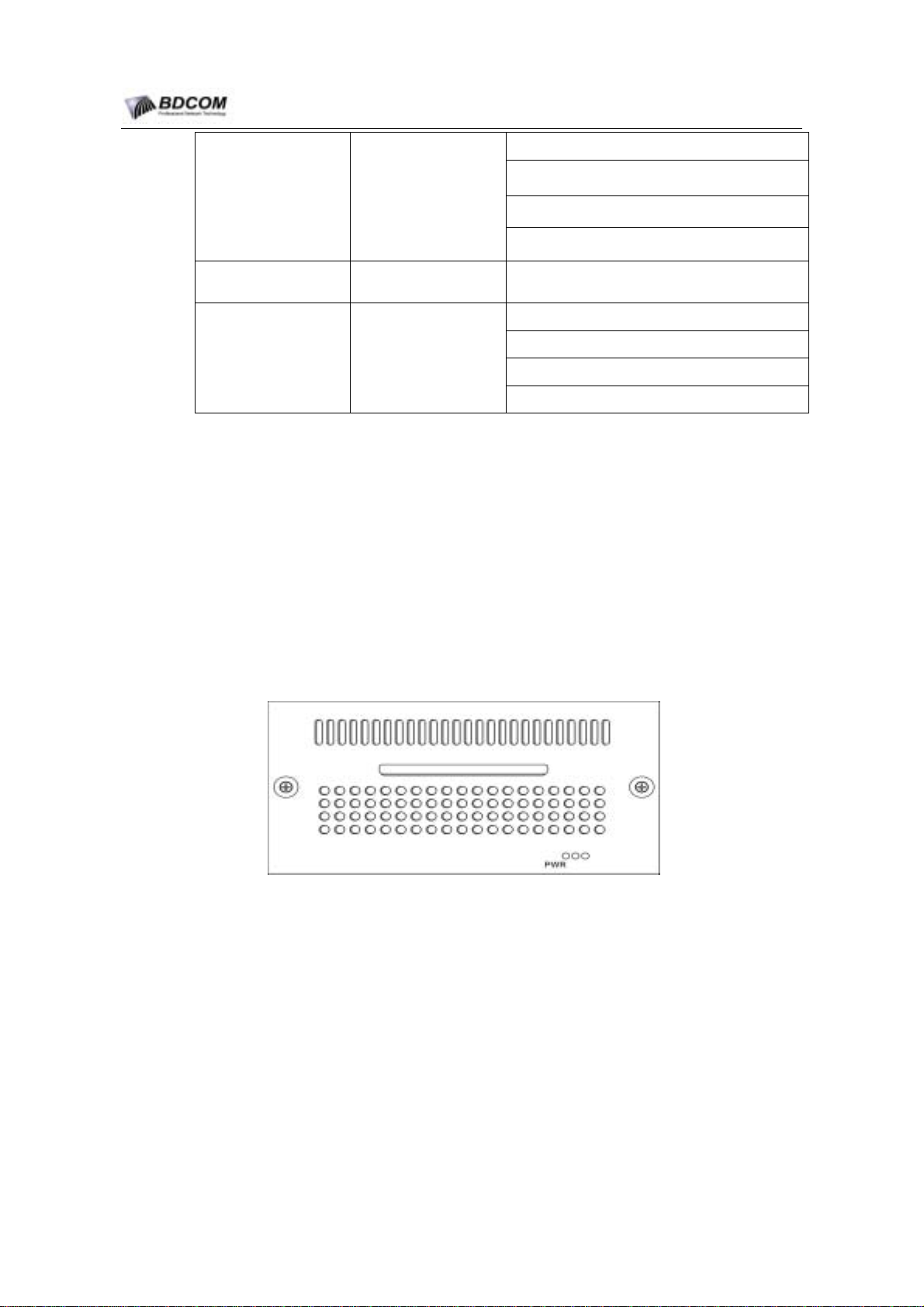
Figure 1-5 LS65-PWR-DC-800 View
~
- 7 -
Page 12
BDCOM S6508 Switch Hardware Installation Guide
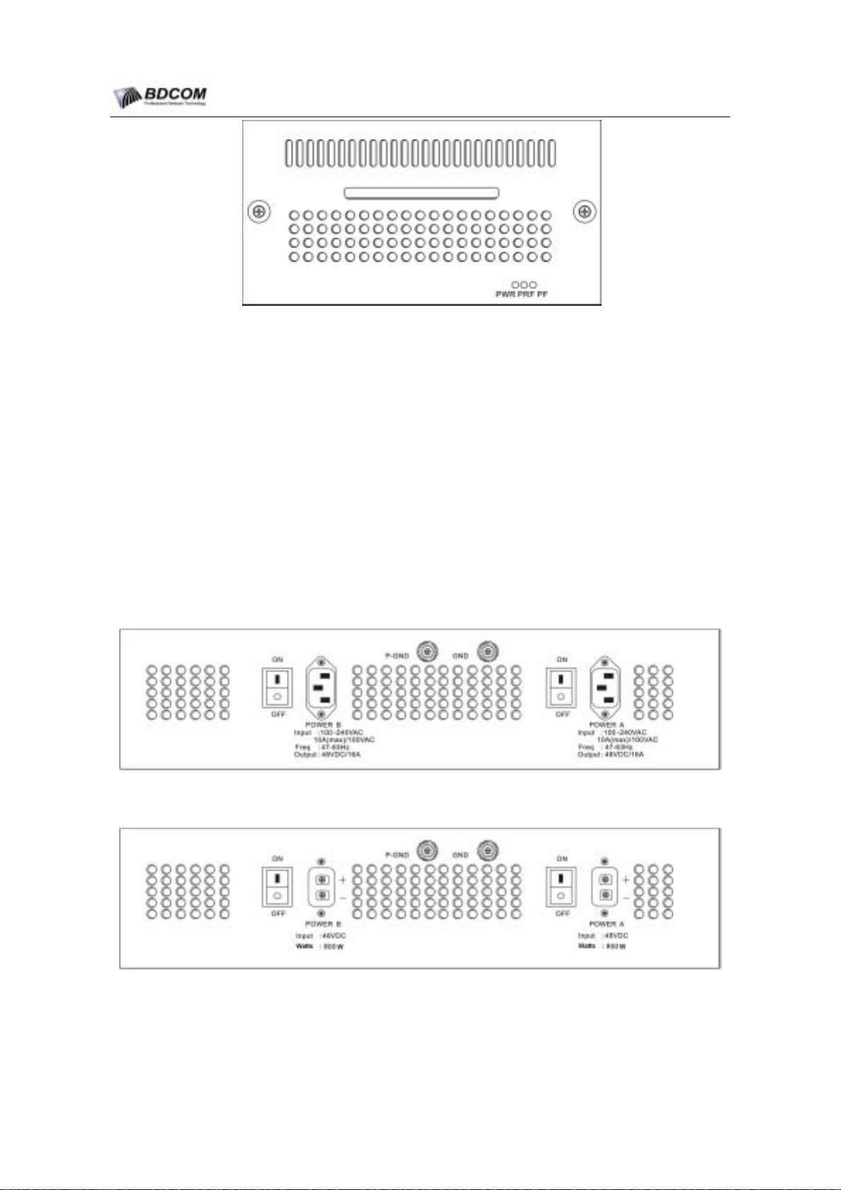
Figure 1-6 LS65-PWR-AC-800 View
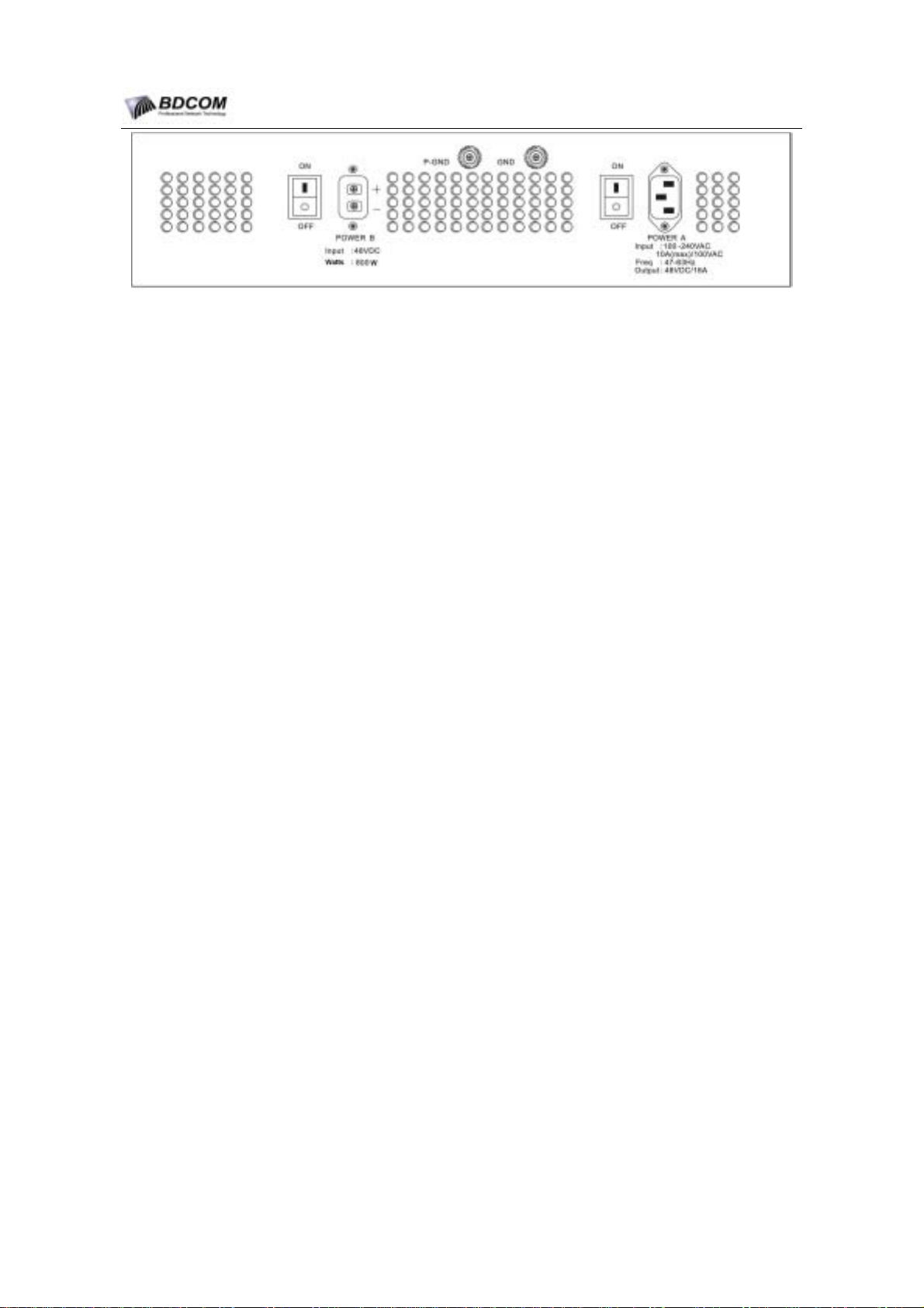
There are 3 Type S6508 Chassis:Double-AC Power Chassis; Double-DC Power
Chassis; AC+DC Power Chassis. For difference environment, user can choose the
type S6508 chassis. The following describes the difference between the 3 type
chassis.
Double-AC Power Chassis: the chassis’s Slot PowerA and Slot PowerB only Support
LS65-PWR-AC-800 module.
Double-DC Power Chassis:the chassis’s Slot PowerA and Slot PowerB only Support
LS65-PWR-DC-800 module.
AC+DC Power Chassis: the chassis’s Slot PowerA only Support LS65-PWR-AC-800
module; the chassis’s Slot PowerB only Support LS65-PWR-AC-800 module.
3 type chassis rear view also are different.The following Figure show the difference.
Figure 1-7 Double-AC Power Chassis Rear View
Figure 1-8 Double-DC Power Chassis Rear View
- 8 -
Page 13
BDCOM S6508 Switch Hardware Installation Guide
Figure 1-9 AC+DC Power Chassis Rear View
1.5 S6508 Switch Airflow
S6508 operate at 0-40℃, The system fan assembly provides cooling air for the MSU
modules and the LPU modules.
Sensors on the MSU modules monitor the internal air temperatures. If the air
temperature exceeds a preset threshold, the TEMPALM LED turns red.
If an individual fan within the assembly fails, the FANALM LED turns red. Then the Fan
assembly should be replaced.
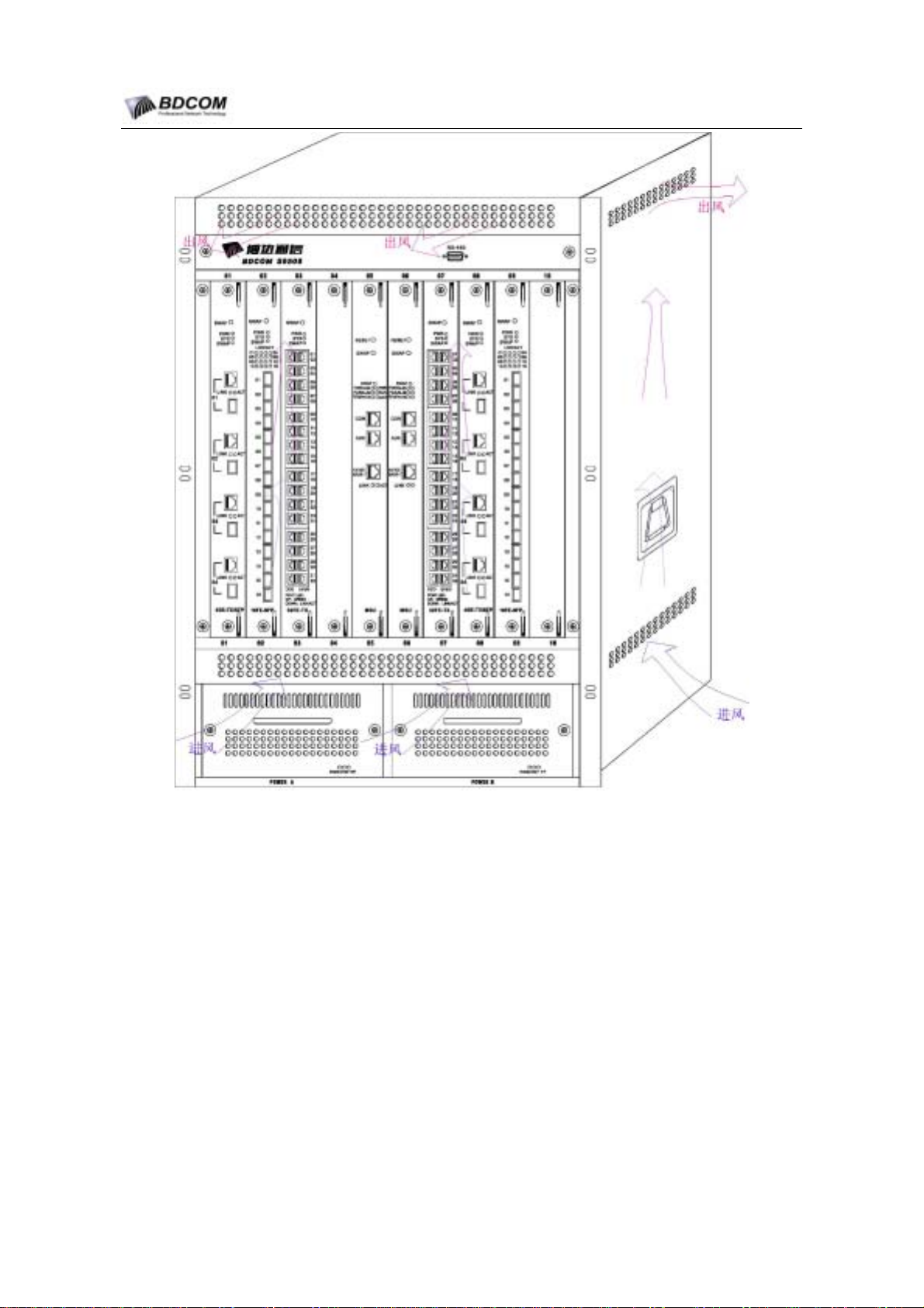
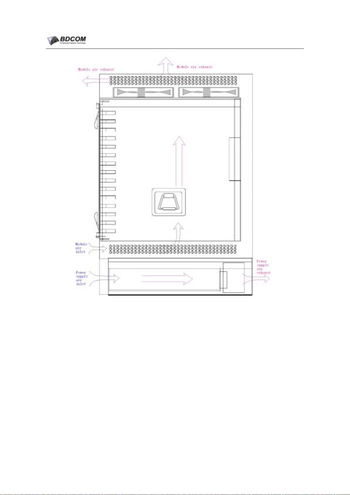
The chassis Airflow is designed as Figure1-5.
- 9 -
Page 14
BDCOM S6508 Switch Hardware Installation Guide
Figure 1-10 S6508 Switch internal Airflow
1.6 S6508 system module overview
S6508 have 5 type system modules.One is MSU module,the other four are LPU
modules.
System Management and Switching Unit module(LS6508-MSU): is the MSU
module. LS6508-MSU is the center of Ethernet Switching. Manage and Control
the S6508 system.
4-Port Gigabit TX/SFP Module(LS65-4GE-TX/SFP): is a type of the LPU
module.
LS65-4GE-TX/SFP module provides 4 switched,full-duplex Gigabit
Ethernet Ports
. Support
Category 5 UTP
cable or Gigabit SFP module.
- 10 -
Page 15
BDCOM S6508 Switch Hardware Installation Guide
4-Port Gigabit SFP Module(LS65-4GE-SFP): is a type of the LPU module.
LS65-4GE-SFP module provides 4 switched, full-duplex Gigabit Ethernet
. Support Gigabit SFP module.
Ports
32-Port 10/100BASE-TX Module(LS65-32FE-TX): is a type of the LPU
module.LS65-32FE-TX module provides 32 switched 10/100-Mbps autosensing,
full or half-duplex ports.
16-Port 100BASE SFP Module(LS65-16FE-SFP):is a type of the LPU
module.LS65-16FE-SFP module provides 16 switched 100-Mbps ports.Support
100BASE SFP module.
1.6.1 System Management and Switching Unit module (LS6508-MSU)
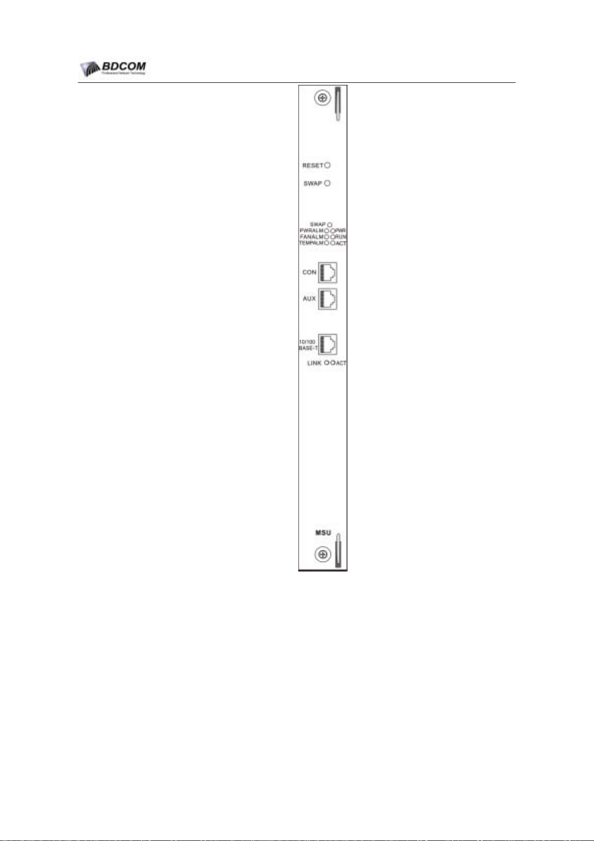
Figure1-11 is System Management and Switching Unit module(LS6508-MSU)front
view. LS6508-MSU is the center of Ethernet Switching.Manage and Control the S6508
system.The chassis provides 2 Slot (Slot 5 and Slot6)for the LS6508-MSU modules.
When two LS6508-MSU modules are all pluged in Slot 5 and Slot 6, one module will
operate at Master status, the other module will operate at Slave status.Then the
system will support Hot-backup.
Two LS6508-MSU modules are configured in one chassis is recommended to get the
system’s high reliability.
- 11 -
Page 16
BDCOM S6508 Switch Hardware Installation Guide
1. Port
2. LED
Figure 1-11 LS6508-MSU front view
LS6508-MSU module provides three Port: Console port, AUX port, 10/100Base-T
Ethernet port.
There are 7 LEDs on the LS6508-MSU front panel.Table1-2 decribes the LEDs means.
Table 1-2 LS6508-MSU module LEDs Decription
- 12 -
Page 17
BDCOM S6508 Switch Hardware Installation Guide
LED Name Decription
3. Button
SWAP
PWR
RUN
ACT
PWRALM
FANALM
TEMPALM
Green means that the MSU module can be hot-pluged out
Off means that the MSU module can not be hot-pluged out
Green means that the MSU Module is Power On
Off means that the MSU Module is Power Off
Flashing Green with 0.5Hz frequency
operates right
.
means that the MSU
.
.
Green means that the MSU Module is at master status
Off means that the MSU Module is at Slave status
.
Red means that something wrong at the system Power
Off means that the system Power is OK
.
Red means that something wrong at the fan assembly
Off means that the system Fan is OK
.
.
.
module
.
.
.
Red means that air temperature exceeds a preset threshold.
Off means that air temperature is OK.
Table 1-3 LS6508-MSU module button decription
Button name Button Decription
RST
SWAP
The RST button allows you to restart the switch.
Use for hot Swap. When use two LS6508-MSU module; one operates at
Master status and the other operates at Slave status. press the master
MSU module SWAP button, the Slave MSU module ture to Master and
the system will light the SWAP LED and Off the ACT LED, then the
MSU module can be hot pluged out.
Use a ballpoint pen tip or other small, pointed object to access the button.
1.6.2 4-Ports Gigabit TX/SFP Module(LS65-4GE-TX/SFP)
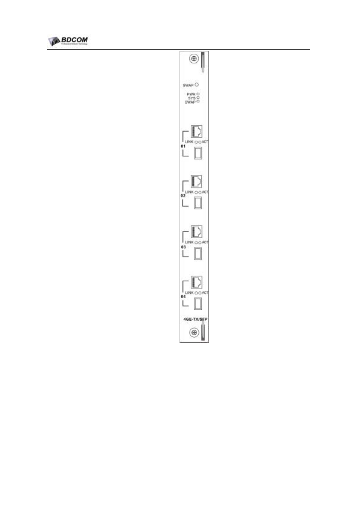
Figure1-12 is 4-Ports Gigabit TX/SFP Module(LS65-4GE-TX/SFP)front view.
- 13 -
Page 18
BDCOM S6508 Switch Hardware Installation Guide
1. Port
Figure 1-12 LS65-4GE-TX/SFP front view
LS65-4GE-TX/SFP module provides 4 switched, full-duplex Gigabit Ethernet
Ports. Every port have one RJ45 Connector and one SFP module connector.
RJ45 Connector Support Category 5 UTP cable. SFP module Connector support
any Gigabit SFP module include 1000BASE-SX, LX/LH, and ZX SFPs, or
copper SFPs. The RJ45 Connector and the SFP module Connector are
autosensing; at the same time, between the RJ45 Connector and the SFP
module Connector in one port, only one can be used. When the RJ45 Connector
and the SFP module Connector are all connected, SFP module first.
- 14 -
Page 19
2. LED
BDCOM S6508 Switch Hardware Installation Guide
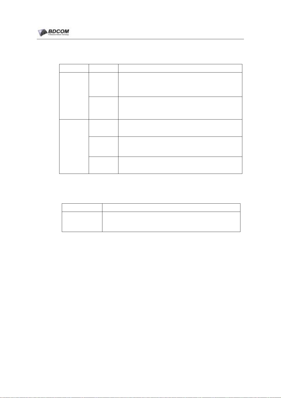
Table 1-4 LS65-4GE-TX/SFP module LEDs Decription
Localtion LED Name Decription
Green means that the Port is active(the link is connected and
In the middle
of the RJ45
connector
and the SFP
module
connector
LINK
ACT
operational).
Off means that the Port is No link.
Green means that the Port is Activity,Port is transmitting or
receiving data.
Off means that the Port is not Activity.
PWR
Off means that the Module is Power Off
Green means that the Module is Power On
On the top of
Panel
SYS
Green means that the Module is active
Off means that the Module is No active.
Green means that the module can be hot-pluged out
SWAP
Off means that the module can not be hot-pluged out
3. Button
Table 1-5 LS65-4GE-TX/SFP module button decription
Button name Button Decription
SWAP Use for hot plug. Press the SWAP button, then system will light the
SWAP Led.When the SWAP Led light On, the module can be hot
pluged out.
1.6.3 4-Ports Gigabit SFP Module(LS65-4GE-SFP)
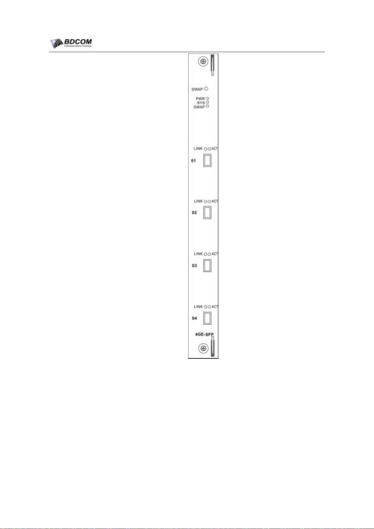
Figure1-13 is 4-Ports Gigabit SFP Module(LS65-4GE-SFP)front view.
.
.
.
.
- 15 -
Page 20
BDCOM S6508 Switch Hardware Installation Guide
1. Port
2. LED
Figure 1-13 4-Ports Gigabit SFP Module(LS65-4GE-SFP)Panel View
LS65-4GE-SFP module provides 4 switched,full-duplex Gigabit Ethernet Ports.The
ports have SFP module connectors for 1000BASE-SX, LX/LH, and ZX SFPs, or
copper SFPs.
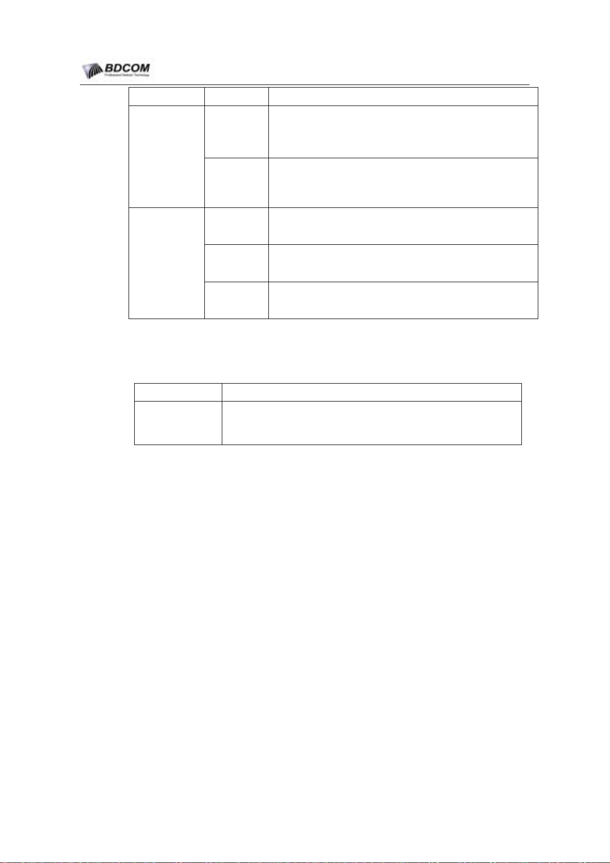
Table 1-6 LS65-4GE-SFP module LEDs Decription
- 16 -
Page 21
BDCOM S6508 Switch Hardware Installation Guide
Localtion LED Name Decription
Green means that the Port is active(the link is connected and
On the top of
ever SFP
module
Connector
LINK
ACT
operational).
Off means that the Port is No link.
Green means that the Port is Activity, Port is transmitting or
receiving data.
Off means that the Port is not Activity.
PWR
Off means that the Module is Power Off
Green means that the Module is Power On
On the top of
Panel
SYS
Green means that the Module is active
Off means that the Module is No active.
Green means that the module can be hot-pluged out
SWAP
Off means that the module can not be hot-pluged out
3. Button
Table 1-7 LS65-4GE-SFP module button description
Button name Button Decription
SWAP
Use for hot plug. Press the SWAP button, then system will light the
SWAP Led. When the SWAP Led light On, the module can be hot
pluged out.
1.6.4 16-Port 100BASE SFP Module (LS65-16FE-SFP)
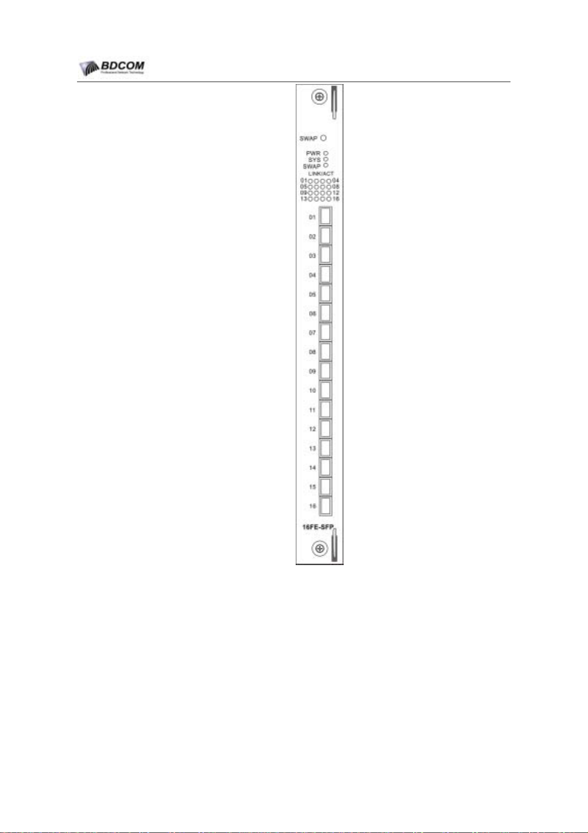
Figure 1-14 is 16-Port 100BASE SFP Module (LS65-16FE-SFP)front view.
.
.
.
.
- 17 -
Page 22
BDCOM S6508 Switch Hardware Installation Guide
1. Port
LS65-16FE-SFP module provides 16 switched 100-Mbps full-duplex ports.The
16 ports have SFP module connectors for 100BASE SFP modules.
2. LED Description
Figure 1-14 LS65-16FE-SFP module front view
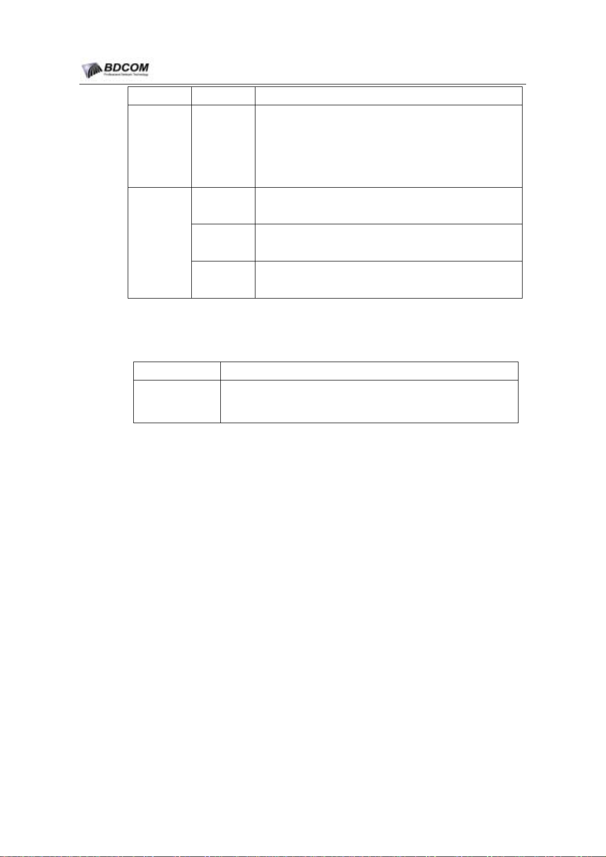
Table 1-8 LS65-16FE-SFP module LEDs Decription
- 18 -
Page 23
BDCOM S6508 Switch Hardware Installation Guide
Localtion LED Name Decription
Green means that the Port is active(the link is connected and
operational).
On the top of
Panel
LINK/ACT
Flashing Green means that the Port is Activity,Port is
transmitting or receiving data.
Off means that the Port is No link.
Green means that the Module is Power On
PWR
Off means that the Module is Power Off
On the top of
LINK/ACT
LEDs
SYS
Green means that the Module is active
Off means that the Module is No active.
Green means that the module can be hot-pluged out
SWAP
Off means that the module can not be hot-pluged out
3. Button
Table 1-9 LS65-16FE-SFP module button decription
Button name Button Decription
SWAP
Use for hot plug.Press the SWAP button, then system will light the
SWAP Led.When the SWAP Led light On, the module can be hot
pluged out.
1.6.5 32-Port 10/100BASE-TX Module(LS65-32FE-TX)
.
.
.
.
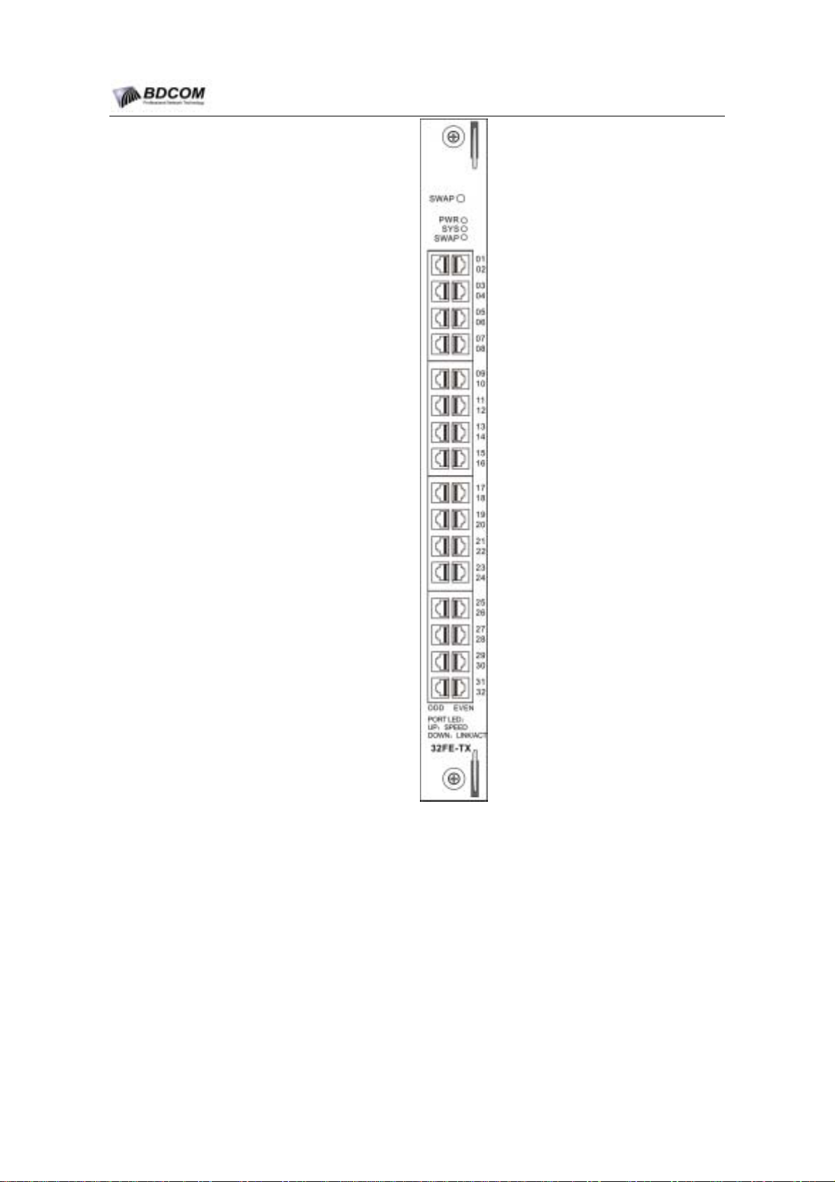
Figure 1-15 shows 32-Port 10/100BASE-T Ethernet Switching Module
LS65-32FE-TX).
(
- 19 -
Page 24
BDCOM S6508 Switch Hardware Installation Guide
Figure 1-15 32-Port 10/100BASE-TX Ethernet Switching Module(LS65-32FE-TX)
1. Port
LS65-32FE-TX module provides 32 switched 10/100-Mbps autosensing, full or
half-duplex ports. The 32 ports have RJ45 connectors for Category 3, Category 5,
Category 5e, or Category 6 UTP or FTP cable.
2. LED
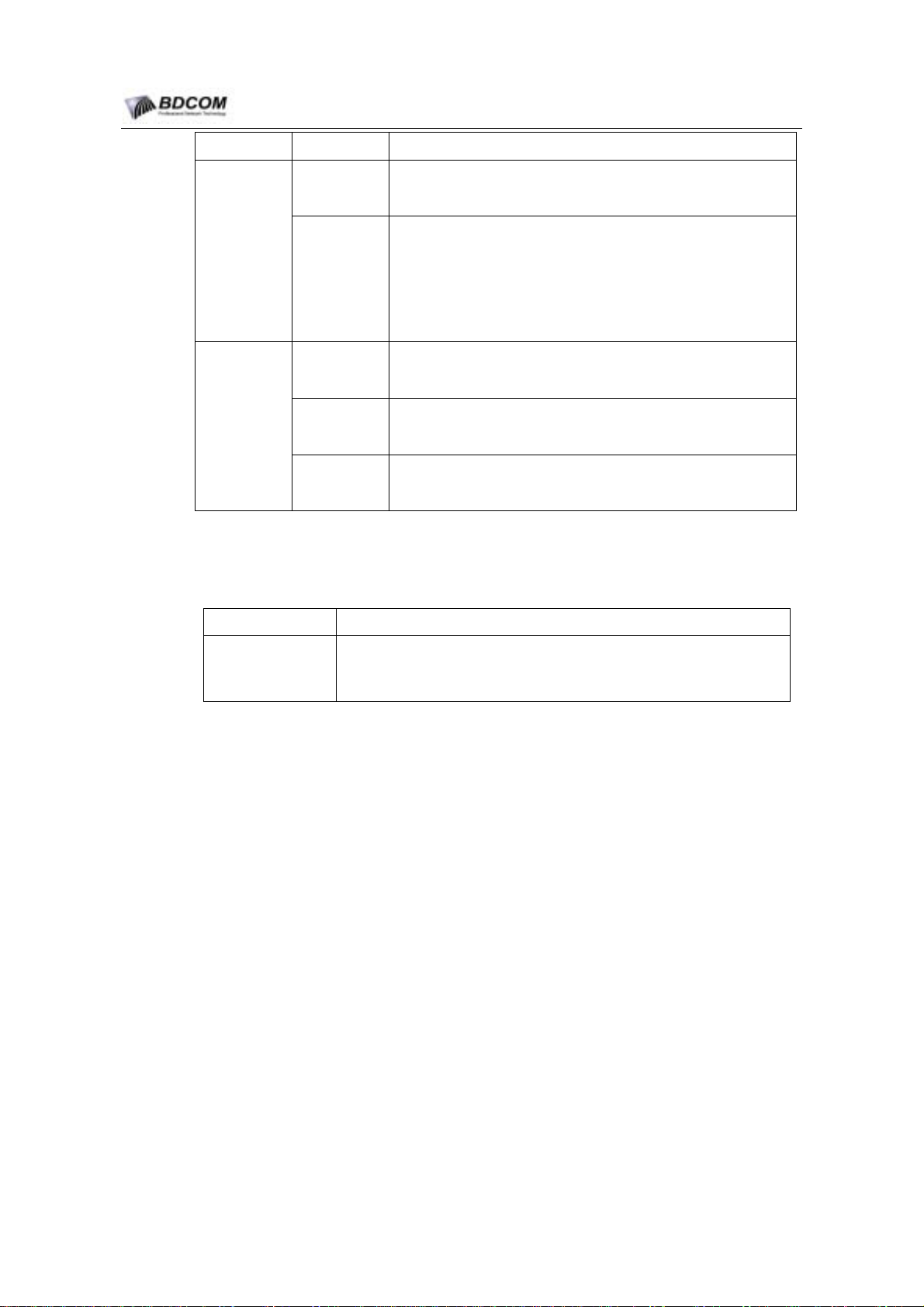
Table 1-10 LS65-32FE-TX module LEDs Decription
- 20 -
Page 25
BDCOM S6508 Switch Hardware Installation Guide
Localtion LED Name Decription
3. Button
SPEEP
Off means that the Port is not operating at 100Mbps.
Green means that the Port is operating at 100Mbps.
With ever
RJ45
Connectors
LINK/ACT
Orange means that the Port is active(the link is connected and
operational).
Flashing Orange means that the Port is Activity,Port is
transmitting or receiving data.
Off means that the Port is No link.
Green means that the Module is Power On
PWR
Off means that the Module is Power Off
On the top of
Panel
SYS
Green means that the Module is active
Off means that the Module is No active.
Green means that the module can be hot-pluged out
SWAP
Off means that the module can not be hot-pluged out
Table 1-11 LS-32FE-TX module button decription
Button name Button Decription
SWAP
Use for hot plug.Press the SWAP button, then system will light the
SWAP Led. When the SWAP Led light On, the module can be hot
pluged out.
.
.
.
.
- 21 -
Page 26

BDCOM S6508 Switch Hardware Installation Guide
Chapter 2 Preparing for installation
2.1 Safety notice
Before you install, operate, or service the system, read the Safety notice carefully. The
Safety notice contains important safety information you should know before working
with the system.
Only trained and qualified personnel should be allowed to install, replace, or service this
equipment.
2.1.1 Ensure safety as the following principals
Keep the chassis ares clear and dust-free during and after installation;
Put the cover in a safe place;
Put the tools away from walk areas where you and others could fall over them;
If the working environment could cause damage to your eyes, wear protection
glasses;
Do not wear loose clothing that could get caught in the chassis. Fasten your tie
or scarf and roll up your sleeves.
Before working on a chassis or working near power supplies, unplug the power
cord on AC unit s; disconnect the power at the circuit breaker on DC units.
Do not do anything that causes damage to human or device.
2.1.2 Safety principal of Moving
Because the S6508 chassis is large and weight, before moving the chassis, read the
following note:
S6508 Weight is about 60kg, Avoid to move the chassis frequently.
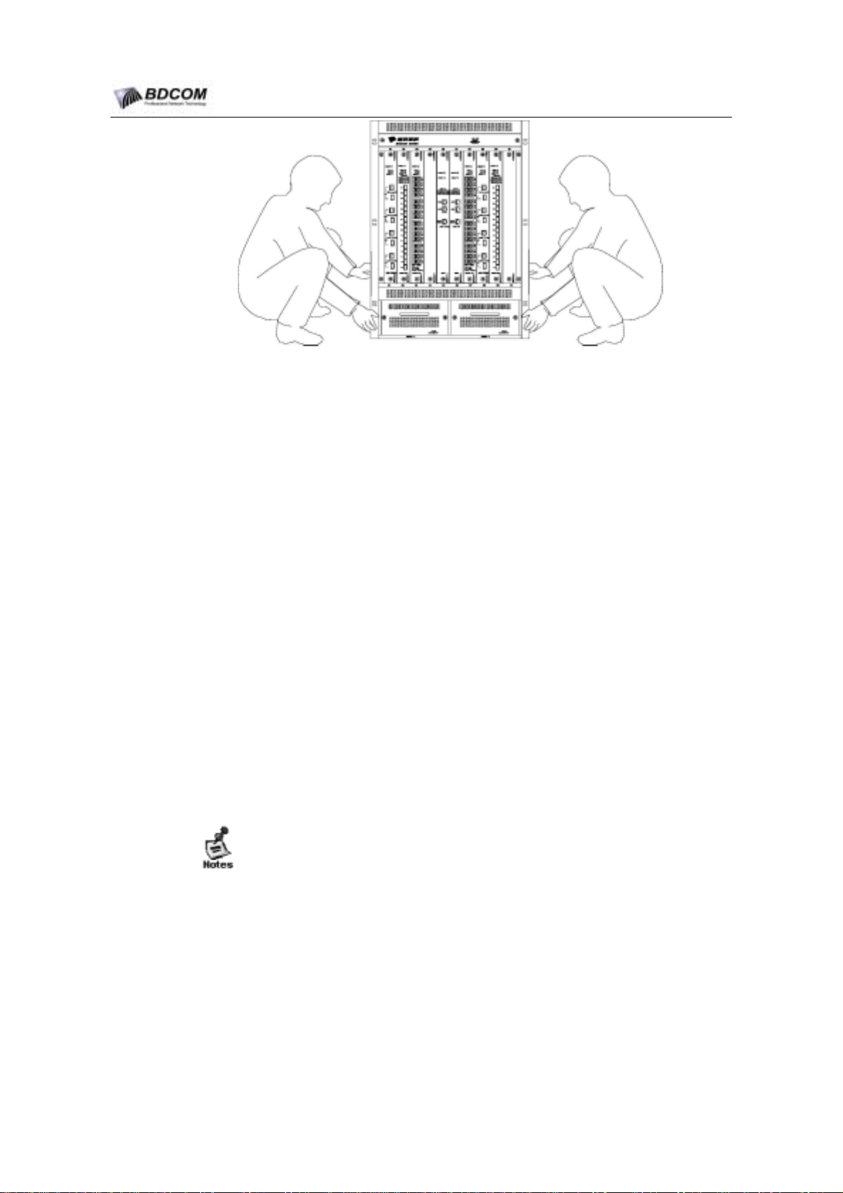
Two people are required to lift the chassis.Moving the chassis by one person is
forbided.
Avoid sudden twists or moves to prevent injury.When moving the chassis,keep
balance to prevent injury.
Before moving the chassis,Turn off the Power and disconnect all the power
cable.
- 22 -
Page 27
BDCOM S6508 Switch Hardware Installation Guide
Figure 2-1 the right way of moving the chassis
The right way is the following: With a person standing at each side of the chassis,
grasp the chassis handle with one hand, and use the other hand near the back of the
chassis for balance. Slowly lift the chassis in unison. Move and keep balance.
2.1.3 Safety principal of operation with electricity
Please check the operating room carefully such as Power Gounding is OK, the
floor is dry. Confirm that there is no hazards.
Before install, Must know the location of the room’s Power switch.
Do not maintenance the S6508 with power on by one person alone.
Do not place the chassis in the wet room, also do not allow the liquid inpour the
chassis.
When using DC-Power to supply, follow the guide to connect the wire.
2.1.4 Preventing Electrostatic Discharge Damage
Electrostatic discharge(ESD) damage, which can occur when electronic cards or
components are improperly handled. This can cause serious damage to the system.
Follow these guidelines for preventing ESD damage:
1) The chassis and the floor have proper gounding.
2) Keep the air clean.
3) Maintain the humidity within an acceptable range.
4) Always use an ESD wrist, and ensure that it makes maximum contact
with the skin.Make sure that the wrist is in contact with bare skin.
- 23 -
Page 28

BDCOM S6508 Switch Hardware Installation Guide
When replace the module or install the module to the chassis,must notice :
Avoid contact between the printed circuit boards and clothing. The wrist strap only protects
components from ESD voltages on the body; ESD voltages on clothing can still cause
damage.
1) When install module, must wear ESD wrist.
2) Handle module by available handles or edges only; avoid touching the
printed circuit boards or connectors.
2.1.5 Laser warning
Always install protective covers on unused or disconnected components to
prevent contamination.
Invisible laser radiation may be emitted from disconnected fibers or connectors.
Do not stare into beams or view directly with optical instruments.
2.2 General site requirements
S6508 chassis should operate in the house.For that the equipment operate well and
prolong longevity of the system, the chassis installed site has the following
requirements.
2.2.1 Reqirements of the rack
If the S6508 is planed to be installed in a rack, please confirm that the following
requirements should be reached.
It’s better to install the switch in openning rack. If the rack is closed, please
confirm that the rack have good airiness for cooling system.
The Rack is strong enough to support the weight of fully configured chassis.
The size of the rack meet the S6508 chassis.There are enough space for airflow .
The rack has proper grounded.
2.2.2 Air Flow conditions
Figure 2-2 shows The chassis airflow. It should have enough space near the air intake
and the air exhaust for the system cooling. After the cables being connected, the
cables should be packed to avoid close the air intake.
- 24 -
Page 29
BDCOM S6508 Switch Hardware Installation Guide
Figure 2-2 S6508 airflow
2.2.3 Temperature and Humidity
To guarantee that S6580 can work smoothly, the temperature and humidity of the
operational environment should be under control.
Otherwise, the equipment may be damaged.
High-humidity conditions can cause moisture migration and penetration into the
system. This moisture can cause corrosion of internal components and
degradation of properties such as electrical resistance, thermal conductivity,
physical strength, and size. Extreme moisture buildup inside the system can
result in electrical shorts, which can cause serious damage to the system.
Low relative humidity can result in electrostatic disarge, which can casue serious
damage to the system.
- 25 -
Page 30
BDCOM S6508 Switch Hardware Installation Guide
Temperature extremes can cause a system to operate at reduced efficiency and
cause a variety of problems, including premature life and failure of chips, and
failure of mechanical devices. Extreme temperature fluctuations can cause chips
to become loose in their sockets.
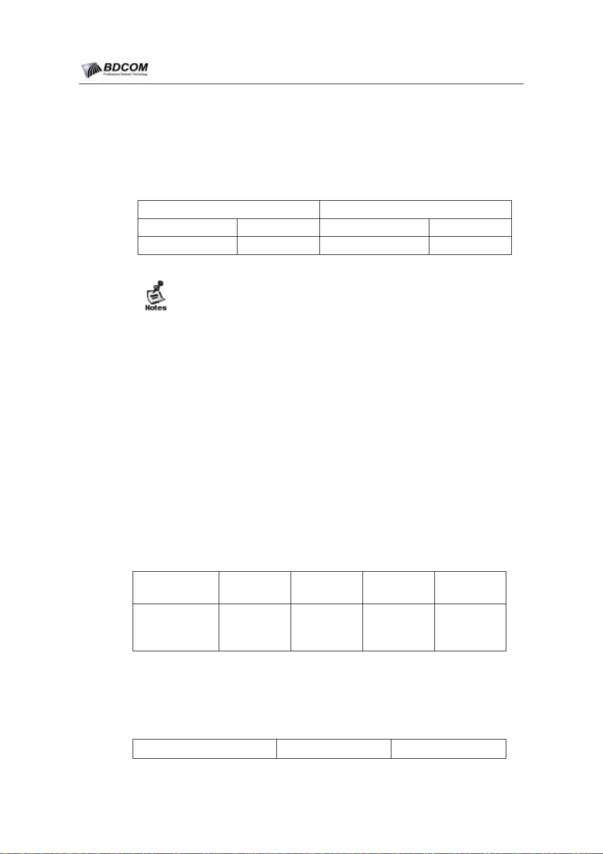
So, the temperature and humidity must be carefully controled to meet the requirements
as illustrated in table 2-1:
Table 2-1 S6508 requirements for temperature and humidity
Temperature Relative humidity
Long term Short term Long term Short term
15ºC-30ºC 0ºC-60ºC 40%-65% 10%-90%
1) The measure point of temperature and humidity about equipment
working environment, is the measure that there is no protection board
on the front and back of bracket. It is the measure numerical value
that 1.5m distance to floor and 0.4m distance to front panel of
equipment.
2) The short time of working condition indicate that the sequence doesn’t
overrun 48 hours and the accumulative total doesn’t overrun 15 days.
2.2.4 Air Environment
Fans will ingest dust and other particles,causing contaminant build up in the system
and increased internal chassis temperature. A clean operating environment can greatly
reduce the negative effects of dust and other particles, which act as insulators and
interfere with the mechanical components in the system.The requirement of the
concentration and the diameter of the dust in the chassis operating room are showed
in Table 2-2.
Table 2-2 Requirements of the concentration and the diameter
max diameter(μ
m)
max
concentration
(number/m3)
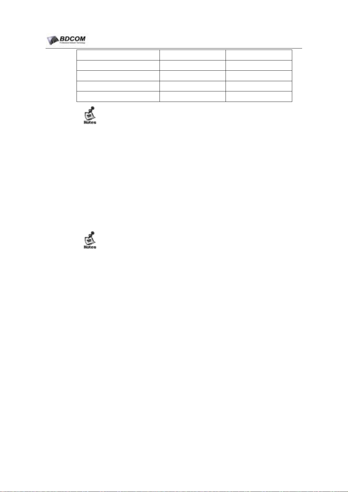
Expect the dust, there are some nocuous gases in air. These gases can cause
corrosion of internal components and degradation of properties. The operating room
must prevent the nocuous gas(Such as sulfur dioxide, sulfureted hydrogen, nitrogen
dioxide, chlorine)in. The limits of nocuous gas are showed in Table 2-3.
3) The extreme scurviness working environment, usually indicate that the
environment temperature and humidity which can get right range
among 5 hours when there is trouble in the room air-condition system.
0.5 1 3 5
4
1.4 x 10
7 x 10³ 2.4 x 10³ 1.3 x 10³
Gas name
Table 2-3 limit of nocuous gas
Nomal(mg/m3 ) Max(mg/m3)
- 26 -
Page 31
BDCOM S6508 Switch Hardware Installation Guide
sulfur dioxide
sulfureted hydrogen
nitrogen dioxide
gaseous ammonia
chlorine
Do not permit smoking anywhere near the system.
Do not permit food or drink near the system.
2.2.5 Power supply condition
When S6508 use AC-Power supply:
AC input Voltage: AC 100V~240V
AC Frequency : 47Hz~63Hz
Power : 800W
When S6508 use DC-Power supply:
DC input: DC -48 V
Power : 800W
0.2 1.5
0.006 0.03
0.04 0.15
0.05 0.15
0.01 0.3
Dual power supplies are recommended in a system. connect each power supply to a
separate input source. In case of a power source failure, the second source should still
be available.
2.3 System Grounding
Grounding is one of the most important parts of equipment installation. When you
properly ground systems during installation, you reduce or prevent shock hazards,
equipment damage due to transients, and data corruption.Please check carfully to
Verify that the site of installing ground have reached the grounding requirements.Make
sure that the grounding is proper.
2.3.1 Grounding Safety
When use AC input, the equipment must be grounder by Kelly ground wire.This can
protect the body.Check the AC power supply outlet to make sure the grounding
condoctor is offered.
2.3.2 Lightning protection
The lightning protection is independence system which includes air terminals
("lightning rods"), connecting cables and clamps, and grounding electrodes.the
lightning protecton is requirement only for the building.the building which the chassis
located must have lightning protection.
- 27 -
Page 32
BDCOM S6508 Switch Hardware Installation Guide
2.3.3 The grounding of EMC
The grounding of EMC includes: screen grounding, rejector grounding, yawp and jam
control, voltage reference. The upwards description come into being the integrate
require of grounding. The grounding resistance must be less than 1Ω.
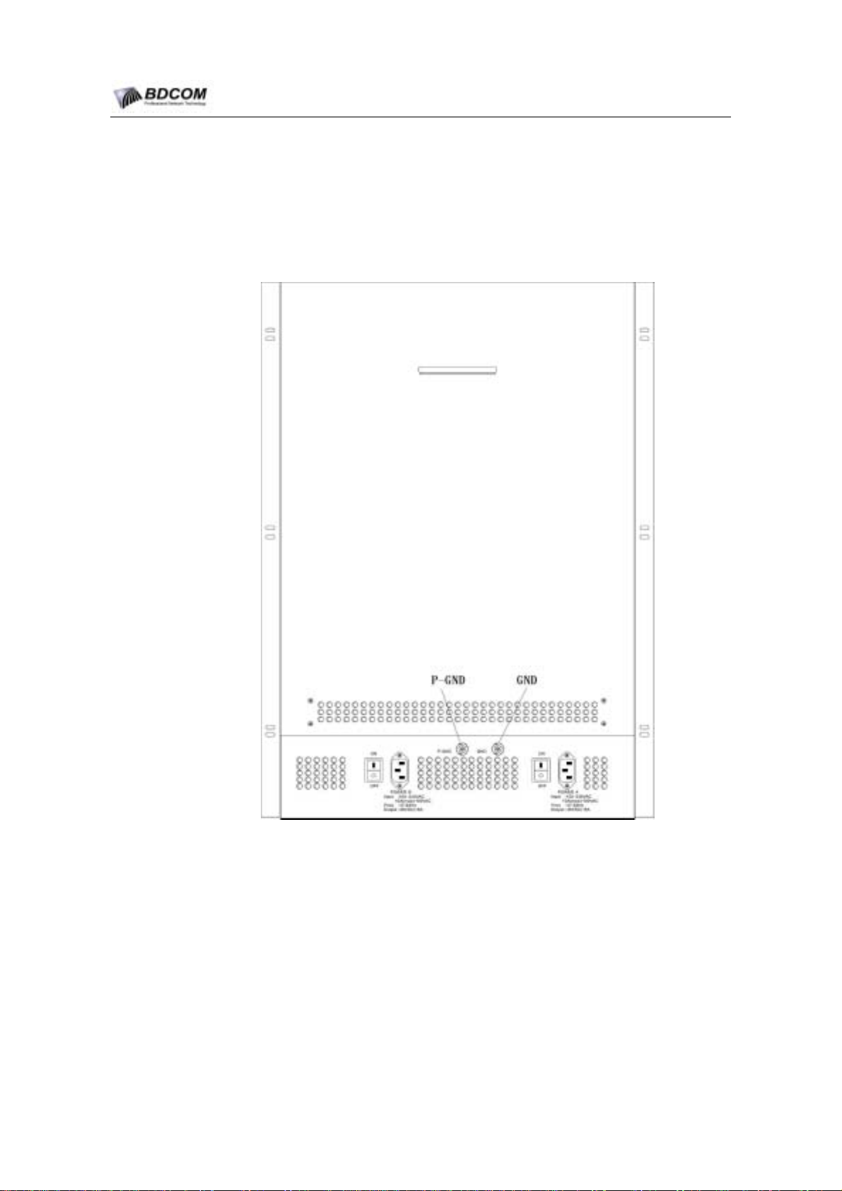
There are two ground connector on the back of the chassis.one is signal ground, the
other is protecting ground.The view like Figure 2-3.
Figure 2-3 S6508 ground connector view
In order to ensure the equipment to run normally, users must read the following notice
proceeding before connecting lines.
2.3.4 EMI calculation
Various interference fountain which comes from equipment or exterior or within of
appliance system, they all can influence the equipment by the conduction mode that
like electric capacity coupling, inductance coupling, electromagnetic wave radiation
and so on.
- 28 -
Page 33
BDCOM S6508 Switch Hardware Installation Guide
There is two types about EMI: radiation interference and conduction interference. It is
decided by the style of transmit path.
When the emanant energy of a parts of an apparatus which is radio frequency energy
get to sense organ through interspace, it is intituled radiation interference. The
interference fountain can be a part of system that is beared interrerence, also can be a
cell that is separated completely by electric. The production of conduction interference
that is because there is connection between fountain and sense organ, the
interference is transmitted from one cell to another cell along the cable. The
conduction interference often influence power of equipment, but it is controlled by
rejector. The radiation interference can influence any signal path of equipment, so it is
difficult to screen.
1) Take effective measure which prevent the interference of electrified wire netting for
power supply system.
2) The switch working place should not share with the grounding fitting of electrical
equipment and preventing thunder equipment. It is better that their distance is
farness.
3) The switch should be far away those strong power wireless launch pad, radar
launch pad and high frequency and strong electric current equipment.
4) It must take measure of static screen.
2.3.5 Fiber-Optic Connectors Note
Always make sure that you insert the connector completely into the socket. Use
extreme care when removing or installing connectors so that you do not damage the
connector housing or scratch the end-face surface of the fiber.
2.4 The request of installation tools
Table 2-4 The list of tools and instruments
Tools
Expert tools
Meter
Screw-driver, pertinent cable and ray cable, bracket bolt,
electric welding, pincers and broad belt.
Electrostatic-protective wrist strap
multimeter
S6508 equipment is no saddlebag, so those tools need to be prepared by users.
2.5 Requirement of checking
The equipment is sent according to the compact,the consignee must check the
equipment by opening the package according the compact.
- 29 -
Page 34
BDCOM S6508 Switch Hardware Installation Guide
2.5.1 Checking Equipment
1. Wrappage of equipment chassis
Confirm that all kinds of faceplate in the equipment are installed OK.
Confirm that the power modul of the equipment is the AC modul or DC modul
whitch required in the compact.
The power cable and ground cable.
Config cable and fiber.
File with the equipment.
Check list about the equiment.
2. Wrappage of faceplate
The backup faceplate of equipment in the box.
It is the usual instance, something maybe different, everything according to the compact.
Please check the equipment carefully according to th compact or the check list about the
equipment ; If have any other questions, please contact the dealer.
3. Check transport box
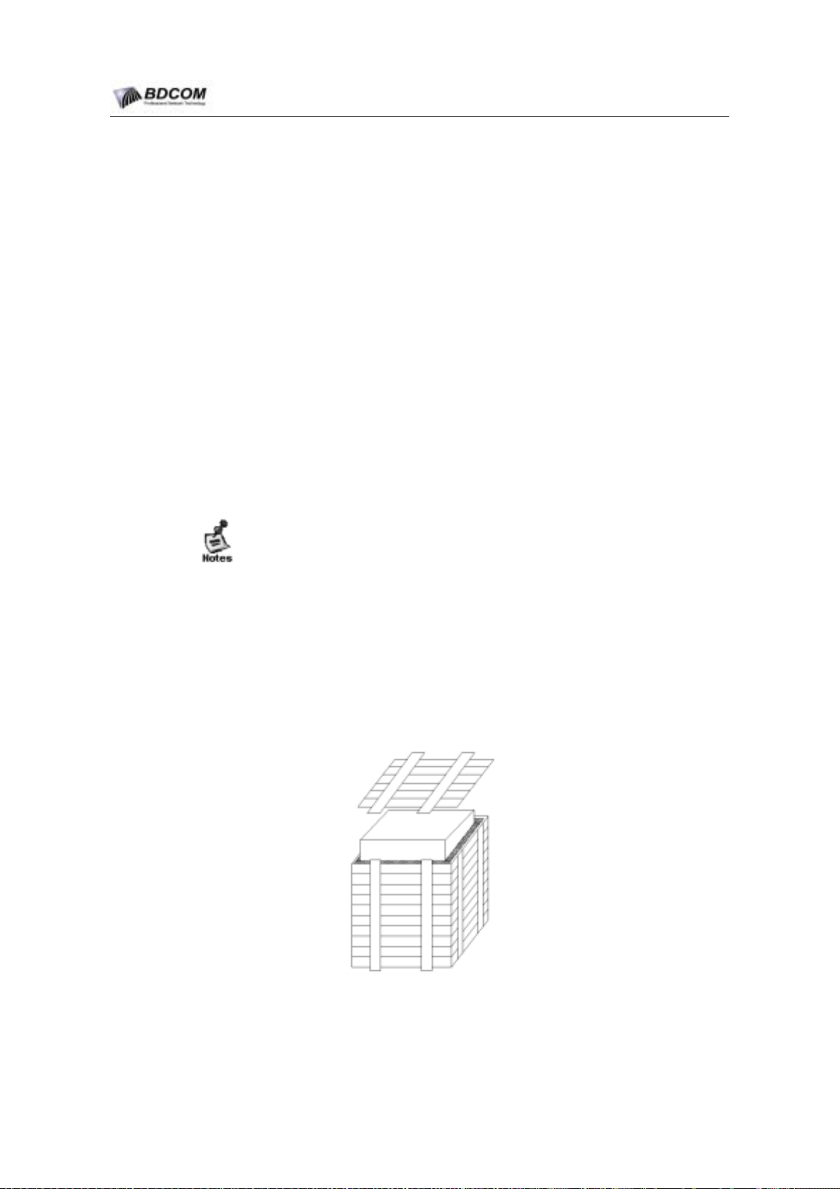
The way that packing the transport box as show in Figure 2-4. After openning the box,
we must check:
Is the shockproof EPE foam in the transport box.
Confirm that the shee box in the transport box isn’t destroyable.
Figure 2-4 transpot box packing
- 30 -
Page 35

BDCOM S6508 Switch Hardware Installation Guide
2.5.2 Record local log
After check all,please labeled on the transport box,and take the relevant record.
Each equipment must have a local log record, including these information: produce
date, debug record, software and hardware version number, product series number.
- 31 -
Page 36
BDCOM S6508 Switch Hardware Installation Guide
Chapter 3 Installing switch
Before install the S6508, please confirm that the chapter 2 has be readed. Please confirm
that the principals are all reached.
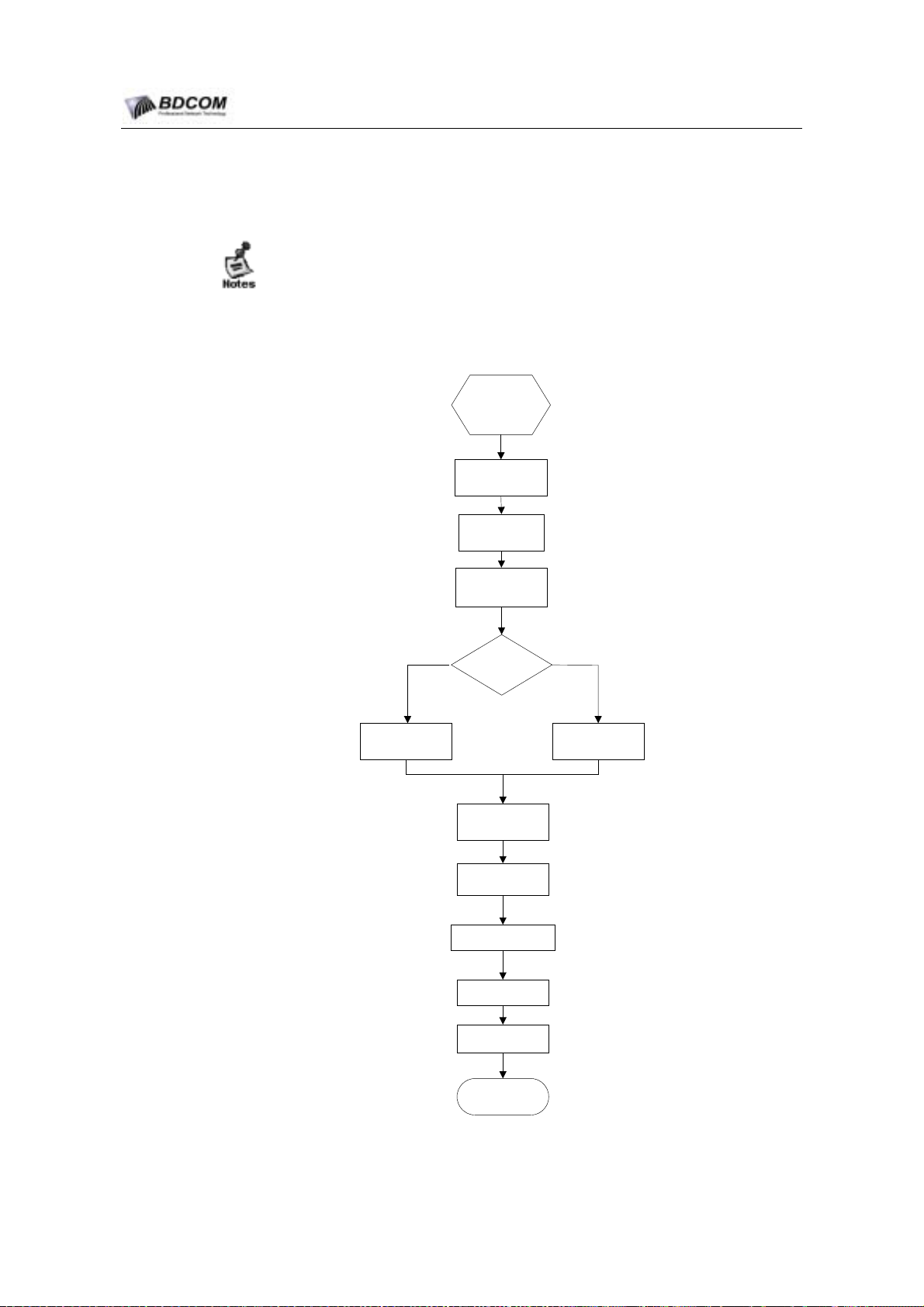
3.1 Installing flow
Prepartion
before
install
S6508
Install rack
Install s6508
on rack
Grounding switch
Connect
power
supply(AC/
DC)
Connect AC power Connect DC power
Connect MSU
cable
Plug info module
Plug cable on
module
Bind cable
Post-check
Install finished
- 32 -
Page 37

BDCOM S6508 Switch Hardware Installation Guide
3.2 Site for installing
Planning a proper location for the switch and layout of your equipment rack or wiring
closet is essential for successful system operation.
Please confirm that the following requirements are reached:
The Site have enough air flowing in the switch.
The Site have enough Power for switch.
The site have enough space to maintain.
3.3 Installing Rack
3.3.1 Notice proceeding
Read the following notes before installing the Rack.
The expand bolt connecting the Rack base and the ground must be installed
complete, the order from up to down must be the nut, the stretch gasket and the
big flat gasket, and the joint between the hole in the chassis base and the
expand bolt.
The Rack must be stably after installing.
The Rack must be apeak after installing.
The Rack must be a beeline with other Rack in the room, the error must be less
than five millimeter.
The front door and the back door must be installed, and be all right when open
and close, the lock is OK, and the key is all ready.
There is no spilth and uncorrective label in the Rack or on the board of the
Rack.
The handle must be installed completely .
The equipment in the chassis must be fixup by bolt, and the bolt must be same.
The singal board of the equipment must be installed fastness, the bolt in the
faceplate must be compactness.
The cable thoughout hole in the Rack top or bottom must install defending
mouse-net, the gap must less than 1.5cm, it can prevent mouse and other little
animal into the Rack.
ESD wrist strap must be equipped in the Rack.
-
- 33 -
Page 38

BDCOM S6508 Switch Hardware Installation Guide
3.3.2 Installing steps
(1) Must have a plane about the room used, make sure that there is enough
tomainenace place before the front door and the back door.
(2) Setting the 19’’ Rack in the appointed place, and fixing it.
(3) Install the cable guides and the connection cable.
(4) Bases the actual instantce, install the stock in the Rack.
3.4 Installing the S6508 chassis in Rack
3.4.1 Notice proceeding
Before installing the chassis in rack, check the location of the brackets are suitable.
After installation, the space between the chassis’s front panel and the rack’s front door
should be over 10CM.
Before installing the chassis in rack, confirm that the rack is fixed and the chassis has
be moved near the rack and there is no obstacle near the rack.
3.4.2 Installation steps
(1) With a person standing at each side of the chassis, grasp the chassis handle
with one hand, and use the other hand near the back of the chassis for balance.
Slowly lift the chassis in unison. Avoid sudden twists or moves to prevent injury.
(2) Insert the chassis between the mounting posts, resting the chassis on the shelf
brackets, and then carefully slide the chassis into the rack.
(3) Install the screws through the holes in the L bracket and into the threaded holes
in the equipment rack posts.
3.5 Establishing the system ground
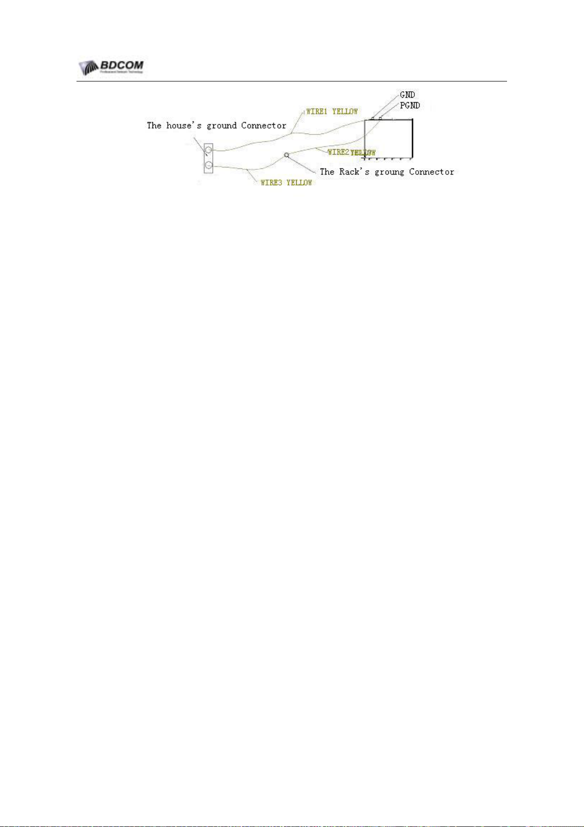
On the back of chassis, there are two ground connector. One is the Signal
Ground(GND), the other is protecting Ground(PGND). GND must connect the Ground
Connector of the house directly. If the the house have analog Grunnd and digtal
Ground, connect GND to the digtal Ground.
Connect PGND to the Rack’s Ground connector,then connect the Rack’s ground
connector to the house’s ground connector. If the the house have analog Grunnd and
digtal Ground, connect GND to the analog Ground.
Establish the system ground as the Figure 3-1.
- 34 -
Page 39
BDCOM S6508 Switch Hardware Installation Guide
Figure 3-1 The system ground of S6508
3.5.1 Notice proceeding
6 AWG wire is recommended.
Do not use naked wire.
The resistance value between the house’s ground connector and the chassis’s
ground connector should be less than 1Ω.
3.5.2 Grounding Steps
(1) Loosen the nut of the ground connector which local on the rear of the chassis.
(2) Connect the right grounding cable to the ground connector.
(3) Tight the the nut of the ground connector.
(4) Connect the ground conector as the figure3-1 by the above steps.
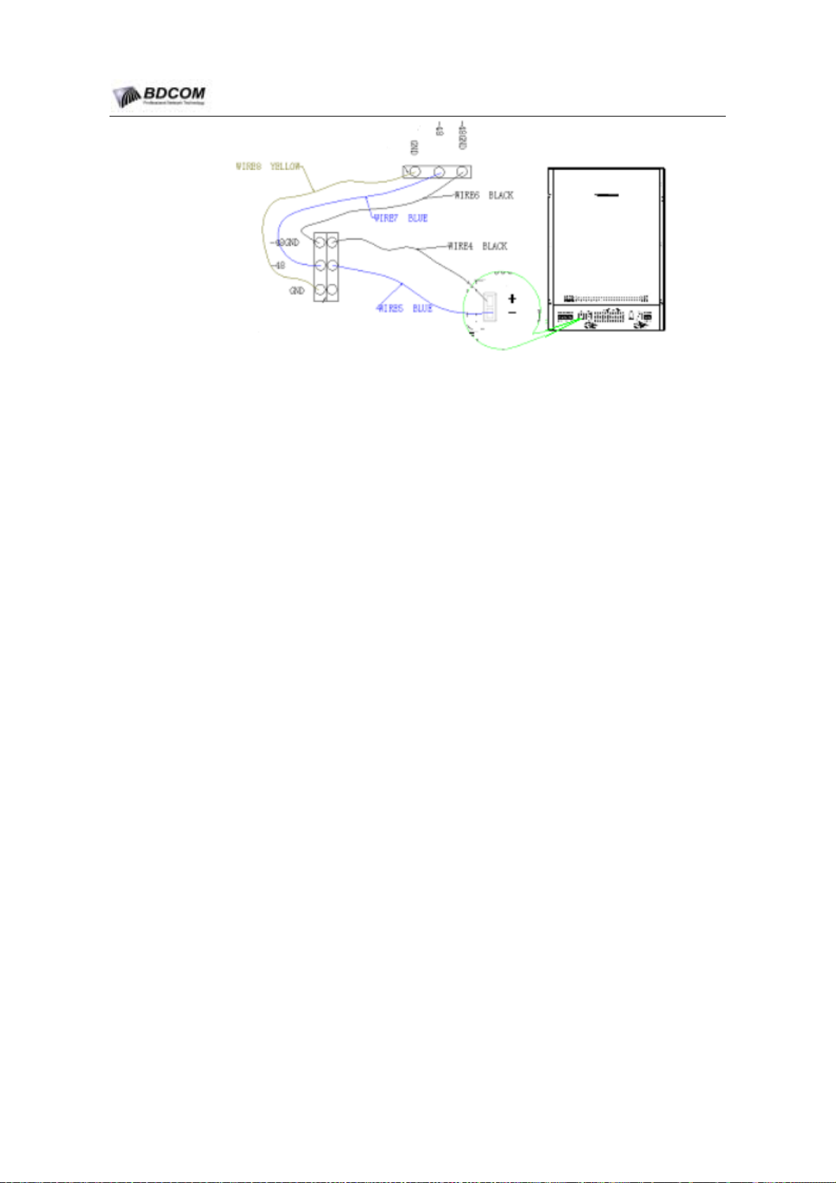
3.6 Connecting the DC Power supply
Look the rear panel of the chassis, and confirm the location of the DC terminal block.
Connect the DC-wires to the right terminal block. The following figure show the right
connection.
- 35 -
Page 40
BDCOM S6508 Switch Hardware Installation Guide
Figure 3-2 DC-wires Connecting
3.6.1 Notice proceeding
Before connecting the DC Power supply,Verify that the DC input reach the
DC-Power supply required.
Before connecting the AC Power supply,Verify that the power switch is the off(0)
position.
Must use the right color power wire to Connect the Power.
Make sure that there is solid metal-to-metal contact.
3.6.2 Connecting steps
(1) Conect the power wires to the right conncetor,tight the screw.
(2) Connect the other end of power wires to the right Power supply connector.
3.7 Connecting the AC Power supply
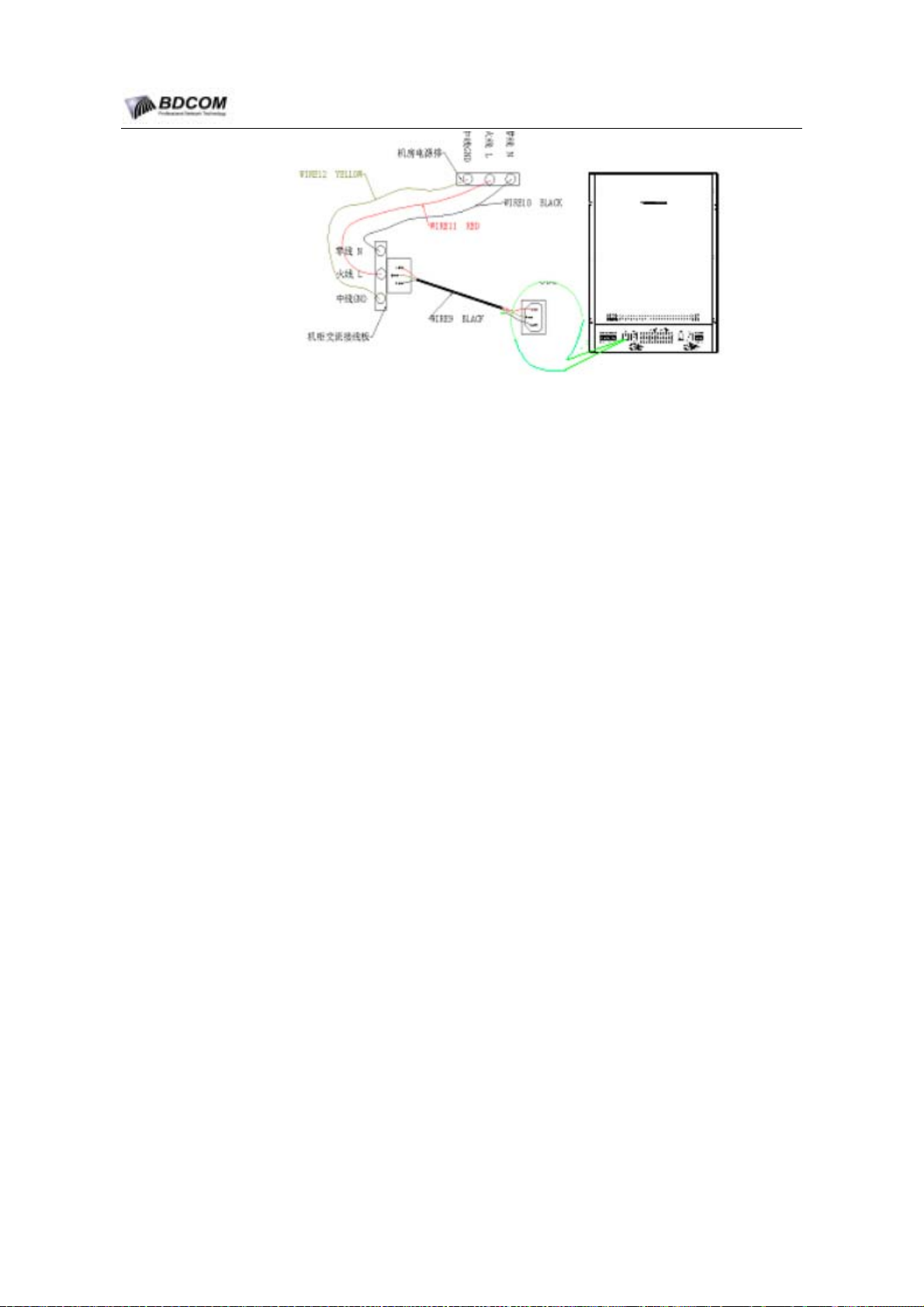
Look the rear panel of the chassis,and confirm the location of the AC terminal
block.Plug the power cord to the power connection.the following Figure show the right
connecting.
- 36 -
Page 41
BDCOM S6508 Switch Hardware Installation Guide
Figure 3-3 AC-wires Connecting
3.7.1 Notice proceeding
Before connect the AC Power supply, please verify that the AC input reach the
AC-Power supply required.
Before connect the AC Power supply, please verify that the power switch is the
off(0) position.
Make sure that the power cord is well connected.
3.7.2 Connecting steps
(1) Plug the power cord into the power connection.
(2) Connect the other end of power cord to an AC-input power source.
3.8 Connect the cable to the LS6508-MSU module
3.8.1 Connecting steps
(1) Plug one end of the Ethernet cable into the FastEthernet interface RJ45 on the
LS6508-MSU module, connect the other end of the cable to the network or to the
control terminal equipment.
(2) Plug one end of the RS-232 serial port console cable into the RS-232 serial port
interface RJ45 on the LS6508-MSU module, connect the other end to the
control terminal equipment.
- 37 -
Page 42
BDCOM S6508 Switch Hardware Installation Guide
3.9 Removing the system Module
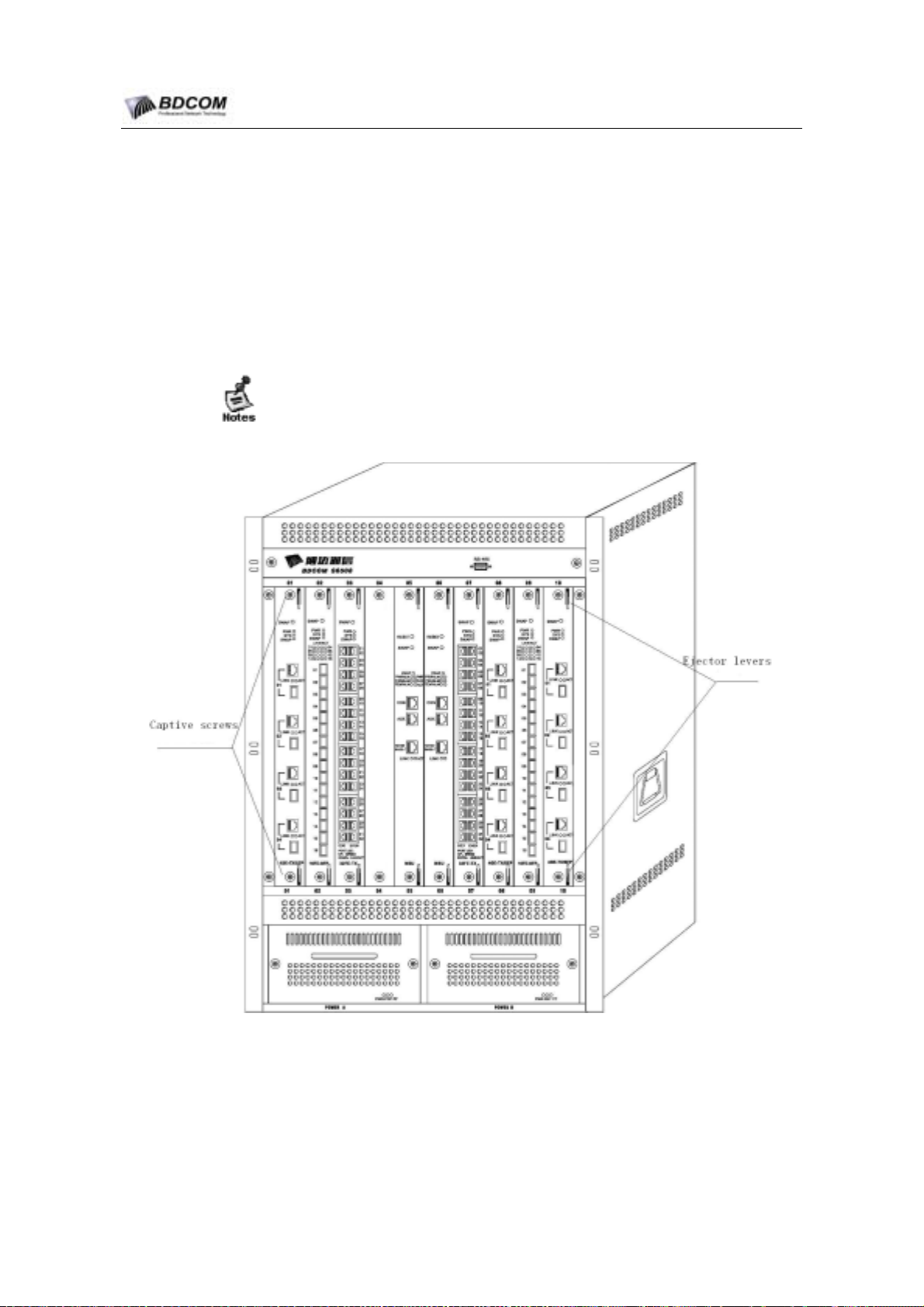
3.9.1 Removing steps
(1) Disconnect any network interface cables attached to the module.
(2) Loosen the two captive screws on the module.
(3) Place your thumbs on the ejector levers, and simultaneously rotate the levers
outward to unseat the module from the backplane connector.
1) Before remove the module,confirm that ESD wrist have be worn.
2) Handle module by available handles or edges only; avoid touching the printed
circuit boards or connectors.
Figure 3-4 Captive Screws and Ejector levers view
- 38 -
Page 43
BDCOM S6508 Switch Hardware Installation Guide
3.10 Installing the system module
3.10.1 Installing steps
(1) Choose a slot for the module.
(2) Remove the module from the choosed slot as 3.9, if there is the other module is
installed in the choosed slot.
(3) Position the module in the slot. Make sure that you align the sides of the
switching-module carrier with the slot guides on the top and bottom of the
slot.slide the module into the slot.
(4) simultaneously close the levers to fully seat the module in the backplane
connector. Tighten the two captive installation screws on the module.
avoid touching the printed circuit boards or connectors.
When Installing or removing the module,Please use ejector levers.
3.11 Connecting external interface cable
3.11.1 Notice proceeding
Distinguish correctly between single-mode and multi-mode fiber.
Avoid small curvature bend at plug.
3.11.2 Connecting Steps
(1) Plug one end of the Ethernet cable into the FastEthernet interface RJ45 on the
LSU module, connect the other end of the cable to the network or to the control
terminal equipment.
(2) Plug single-mode and multi-mode fibers into corresponding interface according
the SFP modules.
(3) Plug all cables and fibers into all modules in turn.
3.12 Packing cable
3.12.1 Notice proceeding
Packing the power cable and other cables to appear orderliness.
Ensure that fiber at plug gets unforced or big curvature bend status.
- 39 -
Page 44

BDCOM S6508 Switch Hardware Installation Guide
Don’t pack fiber and cable too tightly so that avoid pressuring on the cables to
reduce service life and performance of cables.
3.12.2 Packing Steps
(1) Pack pendent fibers and cables of all modules, and make them to branch either
side of the chassis according to convenience.
(2) At all sides of the chassis, fix all fibers and cables by chassis pack cable ring or
cable guides.
(3) For power supply cables, extend under the chassis when packing.Ensure that
cables cling to the chassis and go straightly.
3.13 Verifying the Switch chassis Installation
3.13.1 Checking the Rack
Confirm that Power supply are matched to the Power switchboard of the rack.
After the chassis being unstalled in the rack, comfirm that the front door and the
back door of the Rack can be closed.
Confirm that the rack is completely fixed and the rack can not move in the rack.
Confirm that the chassis is completely fixed and the cables are fixed on the rack.
3.13.2 Checking the connecting
Confirm that the fibers and the cables are matched to the interface.
Confirm that the way of packing cable is right.
3.13.3 Checking the Power
Confirm that the power wire connecting is good and safty.
Confirm that the captive screws on the power supply module panel are tighted.
Turn on the power switch, and verify that the power module can work normally.
- 40 -
Page 45
BDCOM S6508 Switch Hardware Installation Guide
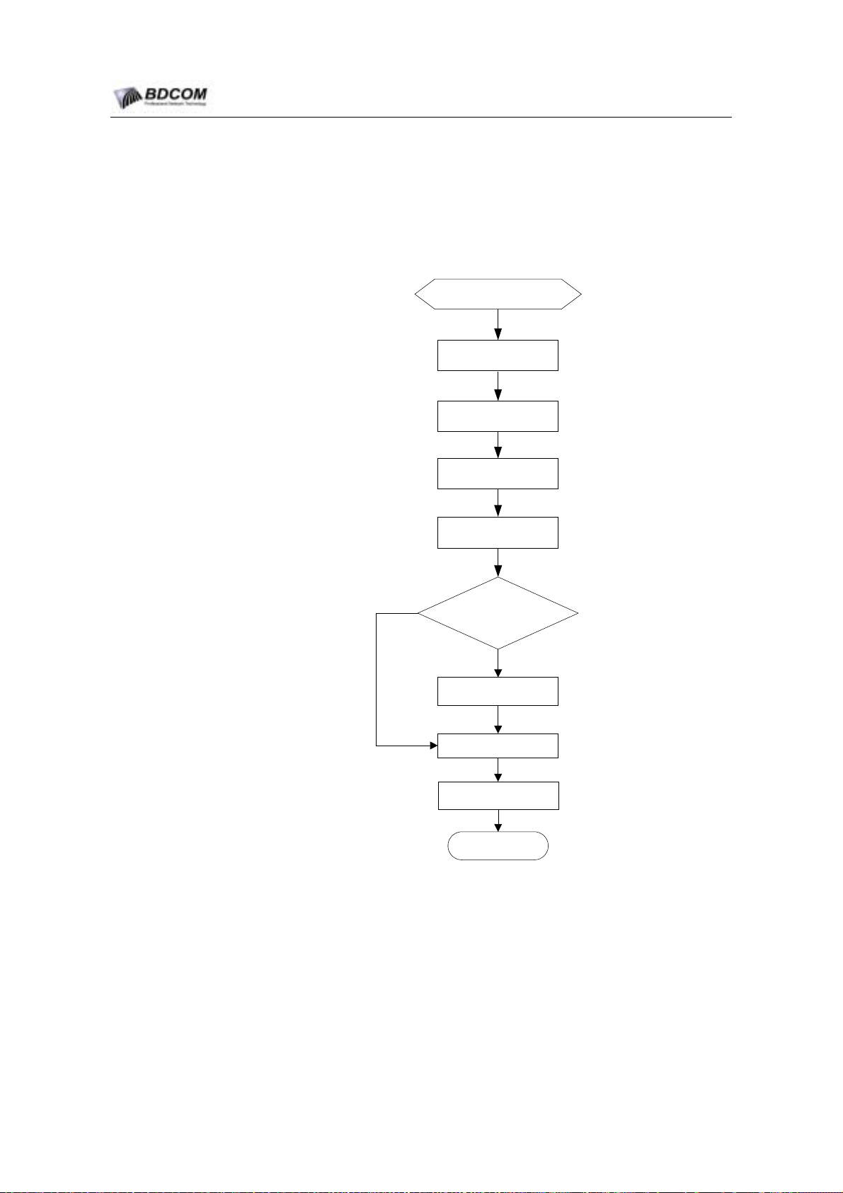
4.1 Debug flow
Chapter 4 System debug
Finish Installation
Set up cofiguration
envirament
Pre-check
Start system
Check Init status
no
Is software exist?
Install software
Config parameter
4.2 set up configurable environment
yes
Run self-test
Debug over
4.2.1 set up configurable environment by console
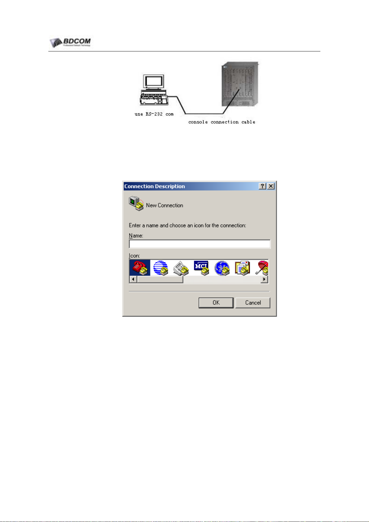
(1) As shown in figure 4-1, to set up local configurable environment, you need
connect PC’s COM port with 6508’s console by RS-232 cable
- 41 -
Page 46
BDCOM S6508 Switch Hardware Installation Guide
Figure 4-1 set up local configurable enviroment by console
(2) Run hyperTerminal program(like Terminal in Windows 3.1 system or
hyperTermial ). if you want to run it, please selet
[program]->[accessary]->hyperTerminal, as shown in figure 4-2.
Figure 4-2 new connection
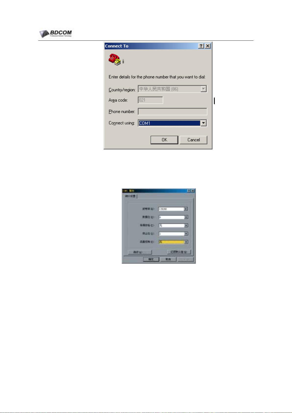
(3) Set up a connection, and set connection port, as shown in figure 4-3.
- 42 -
Page 47
BDCOM S6508 Switch Hardware Installation Guide
Figure 4-3 COM port configration
(5) Config communication parameter is: 9600bps, 8 data bit, 1 stop bit, no parity, no
flow control, terminal type is set to VT100.
Figure 4-4 COM parameter configration
After POWER on, system will run self-checking, after self-checking, switch will prompt
user to input <ENTER>, until command prompt string is displayed.
Input command, config S6508 or watch S6508 run-time status, if you need help, you
can input “?” at any time, specific information about command see 《S6508 Switch
command manual》.
- 43 -
Page 48

BDCOM S6508 Switch Hardware Installation Guide
4.3 Check the status before system operating
4.3.1 Power Check
(1) Set the on-off of 220V AC or –48V DC power on the chassis to OFF status; set
all AC electric supply socket and device power supply switch that link to devices
and terminals to OFF status; set the on-off of all two power supply module of
s6508 to OFF status.
(2) Check to confirm that there is no short circuit among fire wire, ground wire, zero
wire of all electric supply socket by multimeter.
(3) If 220V AC supply is used, turn on the 220V AC power supply switch on the
chassis, check to confirm that the AC input is in normal range(from AC 100V to
AC 240V)by multimeter.
(4) If –48V DC supply is used, first check to confirm that there is no short circuit
among the three power supply end of –48V, GND, PGND on the chassis electric
switchboard. Second, turn on the switch of –48V DC power supply, check to
confirm that the voltage between –48V and GND and the voltage between –48V
and PGND are normal(from DC –72V to DC –36V)by multimeter.
(5) If 220V AC power supply input is ok, turn on the switch of the power supply
module, all module’s PWR indicator lights are lighted. The fans of fan board in
the chassis are turned on, and if they aren’t running normally, fan board should
be taken out to check.
(6) If -48V DC power supply input is ok, turn on the switch of power supply module,
all card’s PWR indicator lights are lighted. The fans of fan board in the chassis
are turned on, and if they aren’t running normally, fan board should be taken out
to check.
4.4 start system and watch initialization status
4.4.1 start system
Usually, software of S6508 should have been installed, software is stored in flash
media of board, so system can normally run once power on.
4.4.2 check version of software and hardware
After system power on, users should check version, ensure it is a legal, release
version. The method of checking version information is using command”show version”,
it will display current version of software and hardware.
switch# show version
BDCOM(tm) S6508 Software, Version 2.1.0D
Copyright by Shanghai Baud Data Communication CO., LTD.
Compiled: 2004-12-28 15:17:31 by WALTER, Image text-base: 0x10000
ROM: System Bootstrap, Version 0.2.5, Serial num:S62000103
- 44 -
Page 49

BDCOM S6508 Switch Hardware Installation Guide
System image file is "12.28.bin"
(RISC) processor with 131072K bytes of memory, 16384K bytes of flash
Base ethernet MAC Address: 00:e0:0f:58:ec:b0
gateway uptime is 1:02:33:25, The current time: 2004-12-30 10:3:19
As shown above, it display version of SWITCH and version of MSU IOS .
4.4.3 source of S6508 IOS
All switch IOS is distributed by Shanghai Baud Data Communication Co., Ltd.
4.5 Install and upgrade S6508 IOS.
Installation and upgradation of system IOS can be run in BOOTROM moniter
enviroment or run-time enviroment, you can also upgrad BIOS in BOOTROM moniter
enviroment.
4.5.1 Installation and upgradation about S6508 system softerware.
1. download switch.bin by TFTP method
(1) Run S6508 system software of MSU, setup configurable enviroment as
mentioned in 1.2, Connect PC’s COM port to console of primary MSU of s6508.
(2) TO finishe installation or upgradation of system software, Use following step to
download system software to MSU.
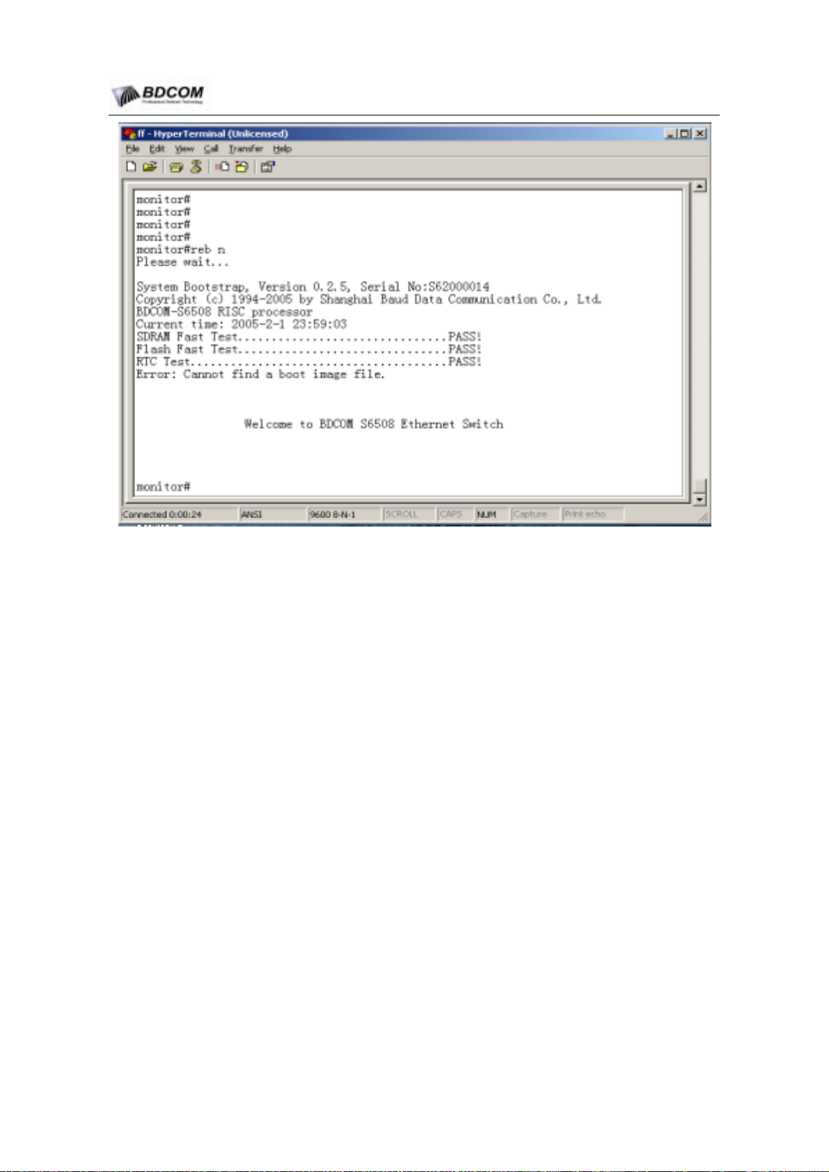
(3) Power on system, when prompt selt-test information, press ctrl+p and enter
system monitor mode.
- 45 -
Page 50
BDCOM S6508 Switch Hardware Installation Guide
Figure 4-5 startup image
(3) Config ethernet ip address
monitor#
ip address <ip_addr
> <
net_mask
>
Patameter explanation:
ip_addr:
net_mask: network mask
For example:
IP address
monitor#ip address 192.168.1.1 255.255.255.0
(4) Test network by ping command
monitor#
<ip_address>: target ip address,
ping <ip_address>
(5) To install or upgrade system software by tftp protocal, input following command:
monitor#
copy tftp flash [ip_addr]
This command is used to opy file from tftp server to flash media of switch, after
enter command, systerm will prompt user enter right server name and file name.
Parameter explanation:
- 46 -
Page 51

BDCOM S6508 Switch Hardware Installation Guide
ip-add is ip of tftp server, if you don’t specify it, system will prompt user to input it
after inputing copy command.
For example:
copy main.bin on tftp server to switch, and rename file switch.bin
monitor#copy tftp flash
prompt:Source file name[]?main.bin
prompt:Remote-server ip address[]?192.168.20.1
prompt:
please wait ...
Destination file name[main.bin]?switch.bin
######################################################################
######################################################################
######################################################################
######################################################################
######################################################################
#############################################
TFTP:successfully receive 3377 blocks ,1728902 bytes
monitor#
2. download system software by zmodem protocal
(1) Run s6508 system software of MSU, setup configurable enviroment as
mentioned in 1.2, Connect PC’s COM port to console of primary MSU of
s6508.
(2) TO finishe installation or upgradation of system software, Use following step to
download system software to MSU.
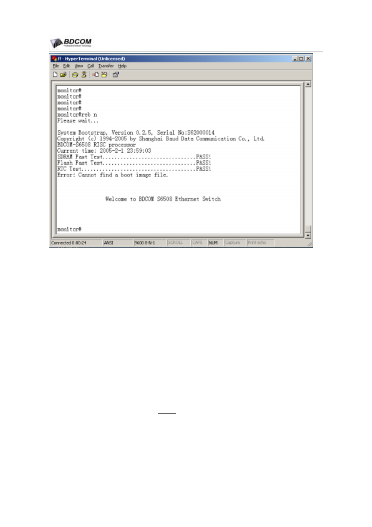
(3) Power on system, when prompt selt-test information, press ctrl+p and enter
system moniter mode.
- 47 -
Page 52
BDCOM S6508 Switch Hardware Installation Guide
Figure 4-6 startup image
(4) Input download command, ”?” will get help
monitor#
download c0 <local_filename>
This command can copy file to flash by zmodem protocal.
Parameter explanation:
local_filename is the filename which is saved in flash, users must input the
filename.
(5) Enter port baudrate
prompt:speed[9600]?
For example:
Terminal program can use Hyper Terminal or termial simulation program.
monitor#
prompt: speed[9600]?115200
download c0 switch.bin
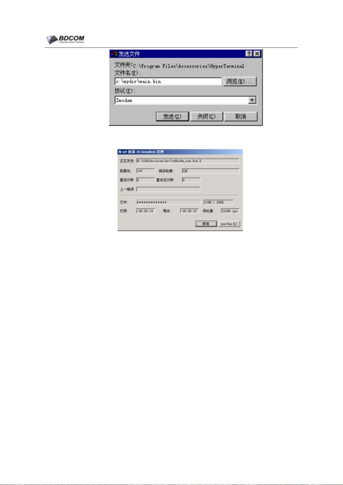
(6) Select transmit menu of terminal program, sending file dialog will be shown, As
shown in following figure. Enter filenam of systerm software in filename area,
select zmodem protocal in protocal area.
- 48 -
Page 53
BDCOM S6508 Switch Hardware Installation Guide
Figure 4-7 send file dialog
Figure 4-8 z-modem download image
(7) Following information will display after transfer file finished
Zmodem receive process completed.
Software transfer successfully, and should reset baudrate of hyperTerminal to
9600bps.
4.5.2 update configuratation
Switch’s config is stored in file, file name is startup-config, user can upgrade
configuration file , same as upgrade system sotrware.
use tftp protocal
monitor#
copy tftp flash startup-config
use zmodem protocal
monitor#
download c0 startup-config
4.5.3 Bootrom upgrade
In some case, bootrom of MSU need to be upgrade, users can set up the configuration
environment according to chapter 1.2. The serial port line connect to the console port
of S6508 MSU.
- 49 -
Page 54
BDCOM S6508 Switch Hardware Installation Guide
1. The steps of downloading the Bootrom by TFTP
Run s6508 system software of MSU, setup configurable enviroment as mentioned in
1.2, Connect PC’s COM port to console of primary MSU of s6508
TO finishe installation or upgradation of system software, Use following step to
download system software to MSU.
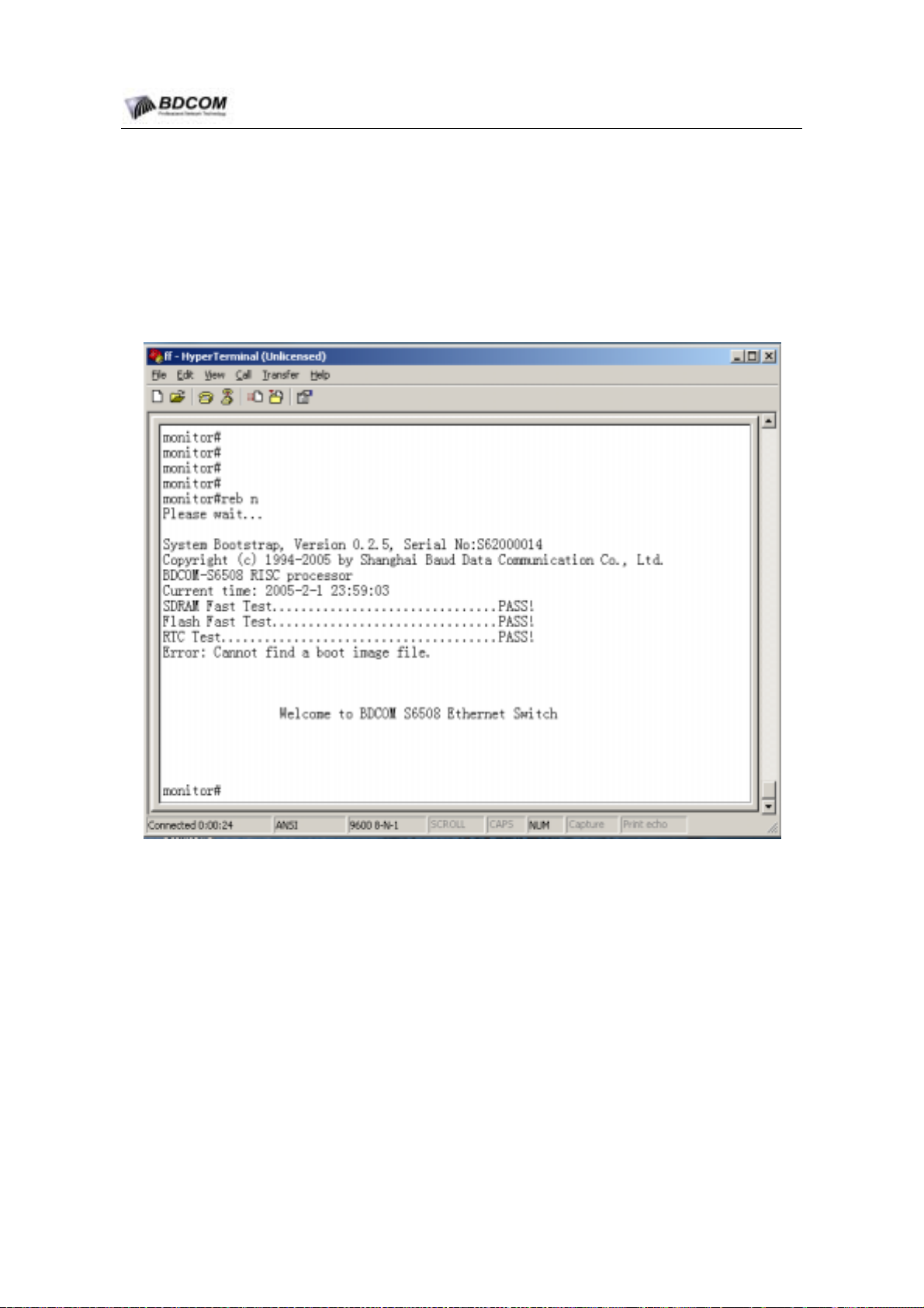
(1) Power on system, when prompt selt-test information, press ctrl+p and enter
system moniter mode.
Carry out the following command:
monitor#
copy tftp rom [ip_addr]
This command is used to download file from tftp server to upgrade bootrom, after type
command, system will prompt user enter server name and file name.
Parameter explanation:
ip-add is tftp serveripaddress.If not appoint, prompt will be shown.
For example:
Copy boot.bin on server, and wirte:
monitor#
copy tftp rom
prompt: Update bootrom is dangerous,do you want to continue(y/n)?y
- 50 -
Page 55

BDCOM S6508 Switch Hardware Installation Guide
prompt: Source file name[]?boot.bin
prompt: Remote-server ip address[]?192.168.20.1
please wait ...
###################################################################
###
###################################################################
###
###################################################################
###
#############################################
TFTP:successfully receive 524288 bytes
Please wait for update Bootrom...
Successfully update Bootrom
monitor#
4.5.4 upgrade in CLI(command line interface)
In order to convenient to upgrade software for on-line manufacture, the system
software provide that upgrade the system software itself and Bootrom software. The
method is similar with that on monitor mode.
1. Use TFTP protocol:
(1) Run system software, enter privilege mode:
switch#
(2) Enter into config mode, config a ip address to a enternet port.
switch#
switch_config#
switch_config_v1#
(3) Use PING to test connection between tftp server and you computer .
switch#
<ip_address>: target ip address, that is tftp server ip address.
config
int vlan 1
ip address <ip_addr> <net_mask>
ping <ip_address>
(4) Install or upgrade system software by TFTP protocol
switch#
After upgradation, return to command line prompt interface.
(5)
copy tftp flash [ip_addr]
- 51 -
Page 56

BDCOM S6508 Switch Hardware Installation Guide
For example:
get a file named main.bin from server, and wirte it to switch store media
switch#copy tftp flash
prompt:Source file name[]?main.bin
prompt:Remote-server ip address[]?192.168.20.1
prompt:Destination file name[main.bin]?switch.bin
please wait ...
################################################################
######
################################################################
######
################################################################
######
################################################################
######
################################################################
######
#############################################
TFTP:successfully receive 3377 blocks ,1728902 bytes
switch#
2. By zmodom method
(1) Run system software, enter privilege mode .
#
switch
(2) Type command:download co ,and type <enter>
switch#
(3)
(4) In terminal program, select menu [Transfer]->[send file…], will eject a send file
dialog , select file in Filename bar, and zmodom in Protocal bar
(5) After z-modem upgrade, return command line prompt interface.
download c0
select baudrate, you can select 110,134,150,200, 300, 600,1200,1800,2400,
4800,9600, 19200,38400,57600,115200 bps.
4.6 basic step of configing S6508
1. enter right config mode
Enter privileged mode when config global parameter, enter corresponding config mode
when config
- 52 -
Page 57

BDCOM S6508 Switch Hardware Installation Guide
2. config data in config mode
In actual work, we need config parameter about system, workload and interface.
Specific parameter configuration can refer to S6508 switch related manual(《S6508
switch configuration manual》 and 《S6508 switch command manual》
You can write Config command into a text file, and mounted the command file directly
into flash. Whole step can refer to chapter “upload and download configuration file”.
In order to use the current configuration into the incept configuration of S6508, please
use “write” command to save the current configuration into incept configuration files of
flash. And users can look over the incept configuration files by “show startup-config”
command.
3. check whether config file is right
After finishing configuration, you can use command”show running-config” to check
current configuration, CURRENT CONFIGURATIION is command that is effect in
current running systerm.
switch#show running-config
Detail about command theroy and command operation, please refer to related
doc(《s6508 switch configuration manual》 and 《s6508 switch command manual》)
4.7 upload and download configuration file
Please refer to 《S6508 switch configuration manual》.
- 53 -
Page 58

BDCOM S6508 Switch Hardware Installation Guide
Chapter 5 S6508 maintenance
5.1 S6508’s monitor function
When S6508 is running, users can watch led status of each board to decide staus of
board. If RUN led is off or blink, probably the board has some hardware or softeware
fault. If ALM led is on or blink, user should check board to ensure what problem exist.
In some case, need first power down machine, then check board.
By some commands, S6508 can also watch system status in run-time, these status
including :
Module or board’s installation status
Physical port’s configuration information and status.
Work-port’s LINK status and traffic st atstic information.
Logic module and system resource’s current status.
Monitor command please refer to S6508’s manual(《S6508 switch configuration
manual》 and 《 s6508 switch command manual》).
5.2 run diagnose function in s6508
S6508 support a lots of debug function when system has problem. Users can turn on
or off debug commands, modify debug level, kind and direction, watch all kinds of
debug, log information in local or remote log server, in order to ensure cause of
problem quickly, so user can in time adjust configuration to switch or network.
5.3 S6508 hardware maintenance
5.3.1 The system module maintenance
when the system module needs to replace because of some trouble, operation should
be processed according to operation step described in chapter 3.8.
5.3.2 Fan assembly maintenance
There are trouble monitor signals for fans, so once trouble takes place, alert will
emerge.
When replacing fans, users should screw off the back board, and pull out
connection-peg.
Replace the broken-down fans by eligible product.
- 54 -
Page 59
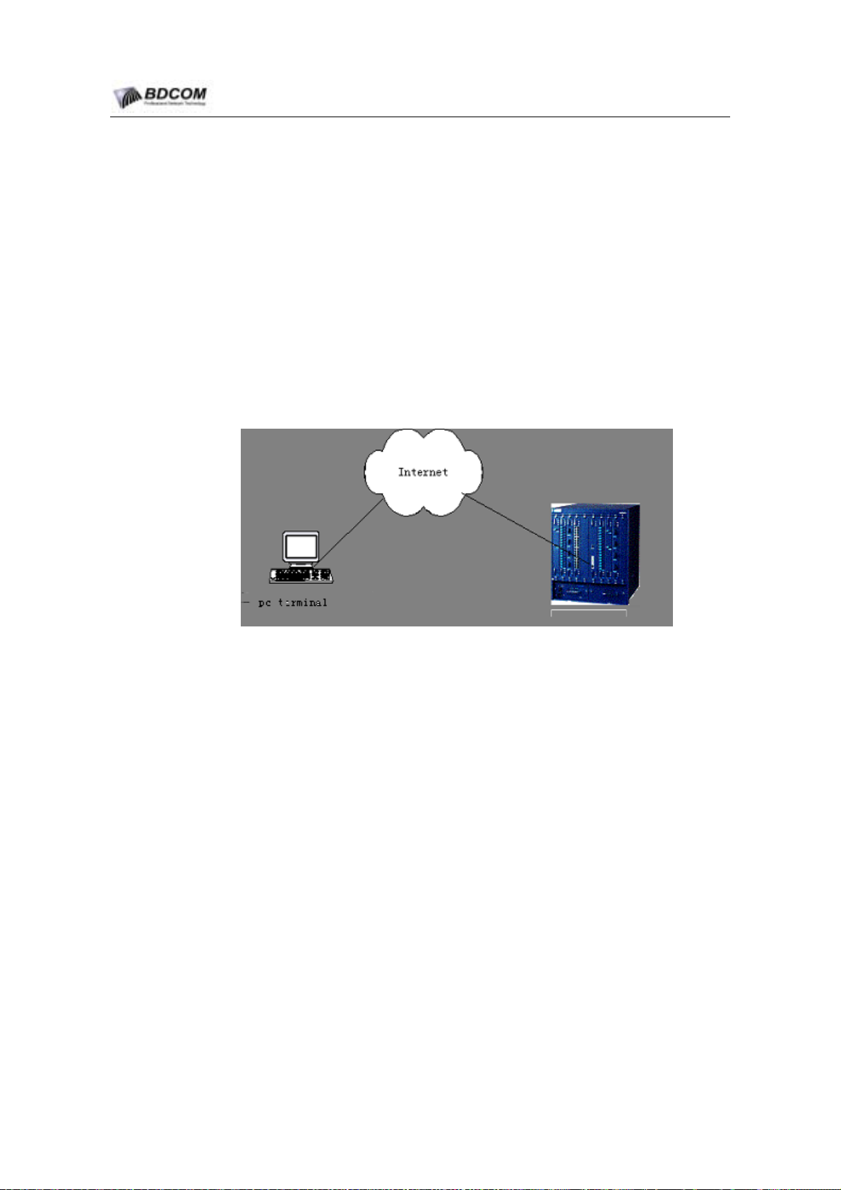
BDCOM S6508 Switch Hardware Installation Guide
Plug in corresponding connection-peg, and close the back board, and give a
good screw.
5.3.3 power supply maintenance
When there is trouble on power supply, user needs to cut off power connect,and pull
out power supply module after loosening two captive screws on the panel of power
supply module.Then after eligible power supply is replaced, give a good screw and
connect power cable.
5.4 remote maintenance
S6508 supports remote maintenance. Users can log on switch by utilizing telnet
method through internet. If switch have been connected to internet, user can log on
switch by telnet method, execute all commands, and run remote maintenance.
figure 5-1 S6508 remote maintenance
- 55 -
Page 60

BDCOM S6508 Switch Hardware Installation Guide
Chapter 6 Hardware Troubleshooting
- 56 -
Page 61
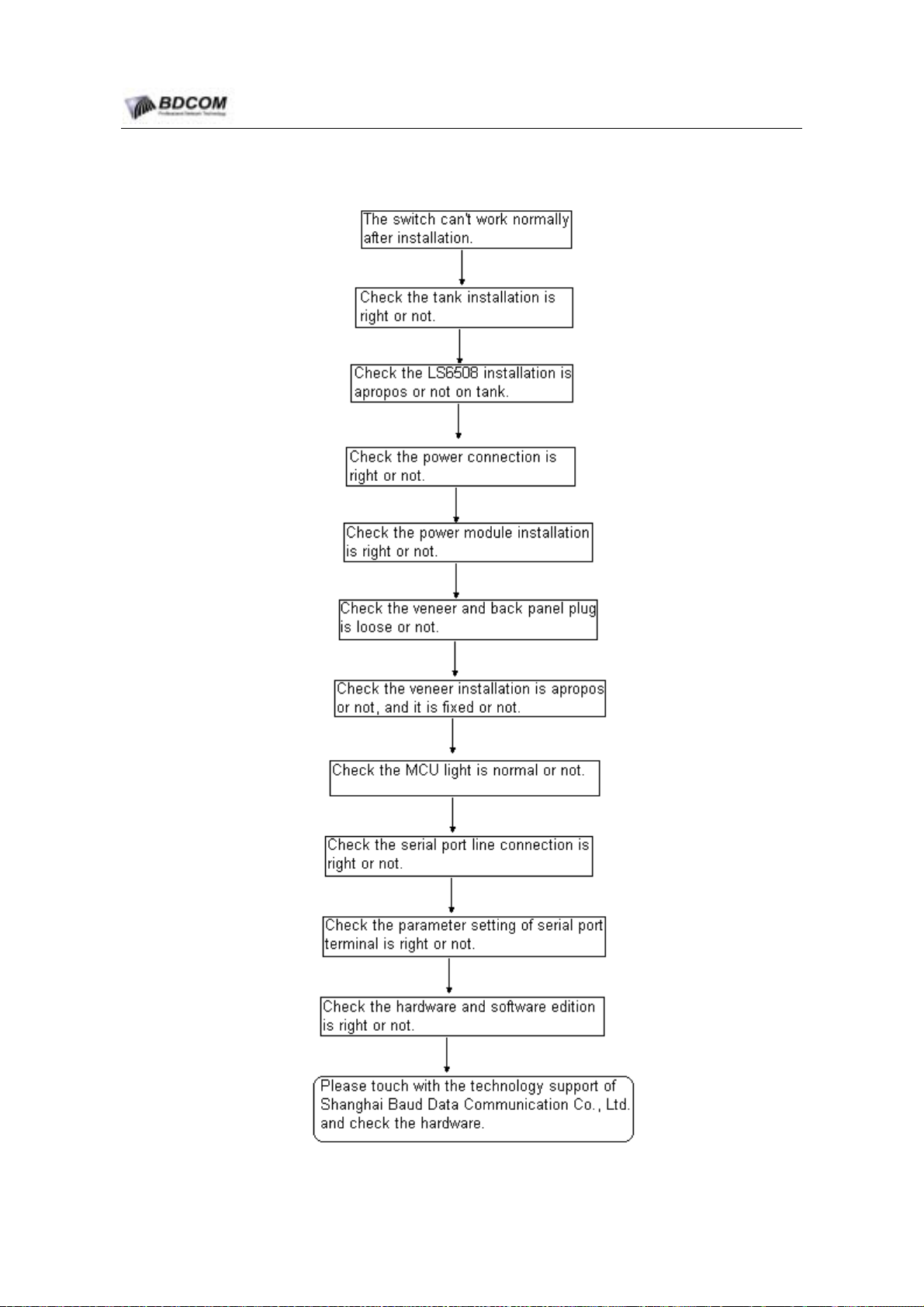
BDCOM S6508 Switch Hardware Installation Guide
6.1 The universal flow of checking installation trouble
- 57 -
Page 62

BDCOM S6508 Switch Hardware Installation Guide
6.2 trouble shooting of losting switch password
【trouble 1】
The login password of system is lost.
【trouble description】
The system login password of switch is lost or forgotten, and cannot config the data.
【trouble shooting】
Power on switch, enter bootrom config mode, delete startup-config, reconfig switch,
restor password, or contact with the technology supporter of Shanghai Baud Data
Communication Co., Ltd.
6.3 deal with hardware installation trouble
6.3.1 trouble shooting about power supply module
【rouble 1】: AC power supply module can’t work.
【trouble description】:
The moudle’s PWR indicator lights are not lighted. Green light on the panel of power
supply module is not lighted. Fans are not running.
【trouble shooting】
First,set the switch of all power supply module to OFF status. Check if the connection
of the chassis is correct. Check if AC feed-in connection is correct. If necessary, pull
out power supply module,and check if the connection between power supply module
and plug on backboard is loose.
【Trouble 2】: DC power supply module can’t work.
【trouble description】
The moudle’s PWR indicator lights are not lighted. Green light on the panel of power
supply module is not lighted. Fans are not running.
- 58 -
Page 63

BDCOM S6508 Switch Hardware Installation Guide
【trouble shooting】
First,set the switch of all power supply module to OFF status. Check if the connection
of the chassis is correct. Check if DC feed-in connection is correct. If necessary,
remove power supply module,and check if the connection between power supply
module and plug on backboard is loose.
6.3.2 trouble shooting about the module installation
【Trouble 3】: indicator light is abnormal after power on.
【trouble description】
SYS indicator light on line card is not lighted. SWAP indicator light on line card is
always lighted. Link indicator light on line card is always lighted when no cable or fiber
is connected.
【trouble shooting】
Check if the system module is installed tightly. If not, install the system module
again,and confirm that the system module is installed tightly, and then give a good
screw. If still not work, check if the corresponding slots of the backplane is loose. If so,
install the system module to other slots to test. And if still not work, send the system
module back to maintain.
【Trouble 4】: indicator light is abnormal after running a while.
【trouble description】
SYS indicator light on line card is not lighted. SWAP indicator light on the module is
always lighted. Link indicator light on the module is always lighted when no cable or
fiber is connected. No change after restart.
【trouble shooting】
Check if the system module is installed tightly. If not, install the system module again,
and confirm that the system module is installed tightly, and then give a good screw. If
still not work, check if the corresponding slots of the backplane is loose. If so, install
the system module to other slots to test. And if still not work, send the system module
back to maintain.
- 59 -
Page 64

BDCOM S6508 Switch Hardware Installation Guide
6.4 trouble shooting about software installation
【trouble 1】
Serical port console is no output.
【trouble description】
After power on, no prompt information in serical console.
【trouble shooting】
First confirm console cable is connected rightly, or cable is broken, connected COM
port is justly port that hyperTerminal program specify. Configuration parameter of COM
port is identify with §4.2 said. If not, please change COM configuration parameter
in accordance to §4.2 . If still no effect, please contact with the technology supporter
of Shanghai Baud Data Communication Co., Ltd.
【trouble 2】
Serical port console output mis-character.
【trouble description】
Serical port console show mis-character, so that it cannot indentification.
【trouble shooting】
COM configuration parameter is wrong, please check it, ensure these parameter is
same with §4.2
- 60 -
Page 65

BDCOM S6508 Switch Hardware Installation Guide
Chapter 7 Appendix
7.1 Identification,Package,Transport,Stockpile
7.1.1 Identification in product
Product Name:“S6508”.
7.1.2 Identification in Package
Product Name:“S6508”.
Company Name:“ShangHai BDCOM”.
Produce Area:“Made in China”.
Leave factory series number.
7.1.3 Produce Area
ShangHai China
7.1.4 Product Type
Network Equipment
7.1.5 Wrapper
The inner wrappwer is plastic bag, The two ends covered by EPE foam, The outside
package is shee box. We reinforce the package by woody box outside the shee box.
The shockproof material is EPE foam between the woody box and paper box. As show
in Figure 7-1:
- 61 -
Page 66
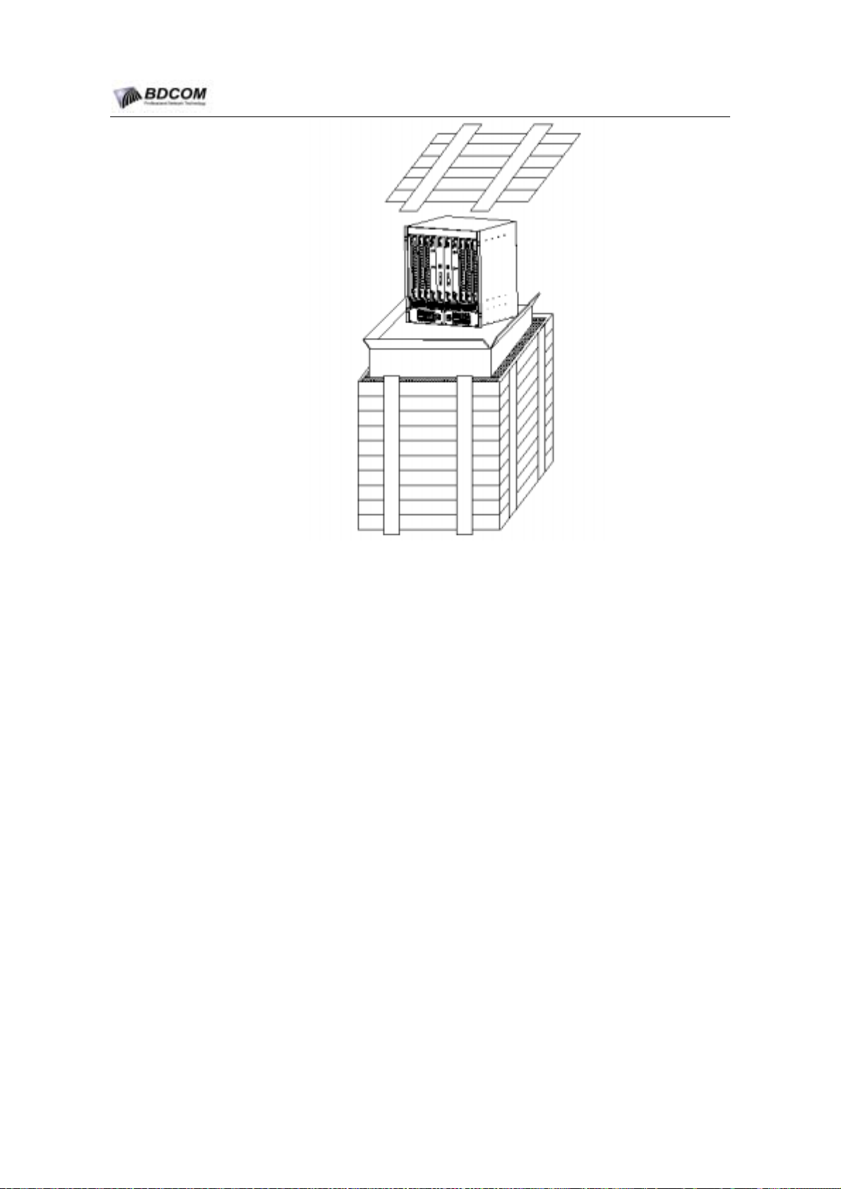
BDCOM S6508 Switch Hardware Installation Guide
7.1.6 Transport
Transport by ship, plane, truck.
Used canopy avoid rainwater in trasport.
Gently move it.
7.1.7 Stockpile
Stockpile location:
Repository.
Stockpile condition
Temperature: -250C~550C.
Humidity: 40%~90%.
Without caustic gas in air
Stockpile requirement
Figure 7-1 Equipment package Figure
Stack height:three layers by outside—package.
Time limit of stockpile
Three years.
- 62 -
Page 67
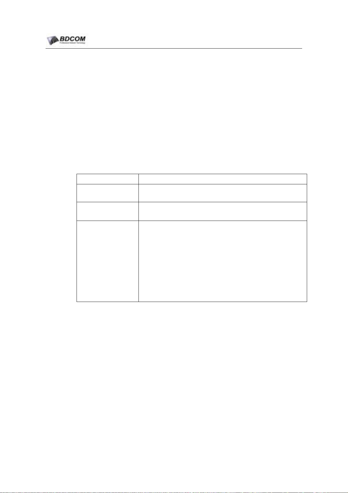
BDCOM S6508 Switch Hardware Installation Guide
7.2 Tools of open and close the package
Tools of open the package
tommy bar, knife.
Tools of close the package
Knife, adhesive tape, nail, hammer, pack band, packer.
7.3 Other
7.3.1 Files in the package
Table 7-1 Files in the package
File name File content
S6508 SWITCH COMMAND MANUAL》,《S6508 SWITCH
User data about product
《
CONFIGURATION MANUAL》,《S6508 Switch Hardware Installation Guide》.
Certificate
Product free maintain
card
Product produce date,checker’s sign or seal( can replaced by
checker’s number).
Product maintain card include these contents:
1.Condition and rule of free maintain.
2.Time limit of free maint a in.
3.The rule about outside free maintain product.
4.The charge exceed the condition and the time limit of free maintain.
5.Free maintain service location Table.
6.Record of maintain.
7.Series number and information record of product free maintain card .
7.3.2 Cables with Equipment
Console cable and power cable is encapsulated by plastic bag.
- 63 -
 Loading...