

Page 1

BDCOM S2008 Switch
Hardware Installation Guide
Page 2

Content
Table of Content
Chapter 1 Information of BDCOM S2008 Switch..................................................................................................................1
1.1 Standard configuration..........................................................................................................................................1
1.2 BDCOM S2008 Switch System Properties Parameters........................................................................................2
Chapter 2 Preparing for installation......................................................................................................................................4
2.1 Safety notice..........................................................................................................................................................4
2.1.1 Ensure safety as the following principals..................................................................................................4
2.1.2 Safety warnings.........................................................................................................................................4
2.1.3 Safety principal of operation with electricity..............................................................................................4
2.1.4 Preventing electrostatic discharge damage..............................................................................................5
2.2 General site requirements.....................................................................................................................................5
2.2.1 Site environment.......................................................................................................................................5
2.2.2 Preventive site configuration.....................................................................................................................6
2.2.3 Configuring Equipment rack......................................................................................................................6
2.2.4 Power supply condition.............................................................................................................................6
Chapter 3 Installing switch....................................................................................................................................................7
3.1 Installation tools and devices.................................................................................................................................7
3.2 Switch Case Installation........................................................................................................................................7
3.2.1 Install on the desk.....................................................................................................................................7
3.2.2 Install on the mounting..............................................................................................................................7
3.3 Connecting Console port.......................................................................................................................................8
3.3.1 Console port connection............................................................................................................................9
3.4 Connecting Fast Ethernet Interface.......................................................................................................................9
Chapter 4 Hardware Troubleshooting.................................................................................................................................11
4.1 Trouble analyzing................................................................................................................................................11
4.1.1 Power and cooling system breakdown.................................................................................................... 11
4.1.2 Ports, cables and connections breakdown.............................................................................................. 11
4.2 LEDs.................................................................................................................................................................... 11
Chapter 5 Switch Maintenance...........................................................................................................................................13
5.1 Open the chassis.................................................................................................................................................13
5.2 Close the chassis................................................................................................................................................14
- I -
Page 3
BDCOM S2008 Switch Hardware Installation Guide
Chapter 1 Information of BDCOM S2008 Switch
This section explains the parameters of BDCOM S2008 switch.
1.1 Standard configuration
BDCOM S2008switch standard ports consists of 2 parts: 8 fast Ethernet interfaces and 1 Console
interface. Refer to the following table:
Features of standard ports:
Port name Features
Fast Ethernet
interfaces
Console
interface
Speed: 10/100M
interface with LINK/ACT, 100 Mbps indicator.
Speed: 9600bps, RJ45 interface
auto-sense
, cable: MDI/MDIX, UTP (RJ45)
In addition, there are 2 extended Ethernet slots in front of the S2008switch, a grounding bar in the rear
and a power supply plug and a power switch (ON and OFF) plug.
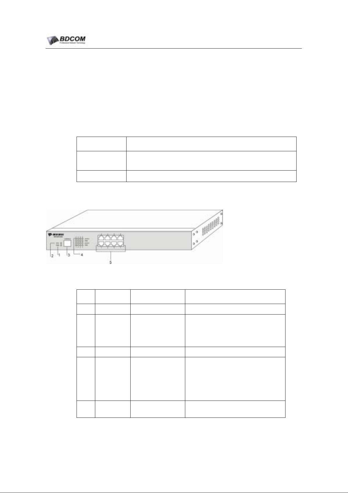
The front-panel of BDCOM S2008 Switch is shown below:
Figuer 1-1 The front-panel of BDCOM S2008 Switch
Components of BDCOM S2008 Switch front-panel:
NO. Name Description
1 PWR
2 SYS
Power indicator lights Switch on and indicator lights.
Indicator lights when the system is turning
System Indicator
on.
Indicator blinks when the systems is
functioning.
3 CONSOLE Console interface Implement Switch Local management.
Indicator lights when the linking is normal.
Indicator blinks when data is being sent or
received.
Indicator lights when the port is in 100M.
Indicator dies out when the port is in 10M.
Implement 10/100 methenet signal
transformation
4
5
Indicator embedded
on each port.
8 10/100-Base-T
interfaces
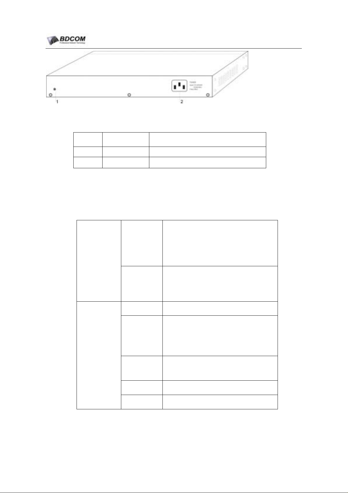
The rear-panel of BDCOM S2008 switch is shown as below:
- 1 -
Page 4
BDCOM S2008 Switch Hardware Installation Guide
Figuer 1-2 The rear-panel of BDCOM S2008 switch
Table 1-1 Components of BDCOM S2008 Switch rear-panel
No. Name Explanation
1 Grounding bar Please ground as needed.
2 AC connector
AC100~240V
Figuer 1-3 BDCOM S2008-DC power rea-panel
1.2 BDCOM S2008 Switch System Properties Parameters
Table of BDCOM S2008 Switch property parameters:
IEEE 802.1d Spanning Tree Protocol
IEEE 802.1p Class of Service
IEEE 802.1q tagged VLAN
IEEE 802.3x Flow control
IEEE 802.3ad Link aggregation
RFC 1213 MIB II
RFC 1493 Bridge MIB
RFC 1643 Ether-Like MIB
RISC200MHz
EPROM:512K Bytes;
Flash Memory:4MBytes;
SDRAM:16Mbytes,
expand
expand
able to 64Mbytes;
able to 8Mbytes
Protocol
Hardware
Features
Standard
Network
Management
Standard
CPU
Memory
Standard
Components
Cards module
Dimension
8 10/100Base-TX ports
1 Console port
10/100Base-TX; 100Base-FX;
340mm×220mm×44mm
- 2 -
Page 5

BDCOM S2008 Switch Hardware Installation Guide
Temperature/H
umidity for
working
Temperature/H
umidity for
storage
Power supply
consumption
Power
0℃~60 ; 10%℃ ~85% without air conditioning
-40℃~80 ; 5%℃ ~95% without air conditioning
Input Voltage: AC100~240V; Input frequency:
47~63Hz
Input current: 1A/230V
MAX:18W
- 3 -
Page 6

BDCOM S2008 Switch Hardware Installation Guide
Chapter 2 Preparing for installation
The following diccusses the considering cases of switch istallation,includes two sections:
Please continre to read "switch Installation" after reading this section.
2.1 Safety notice
2.1.1 Ensure safety as the following principals
1. Keep the chassis ares clear and dust-free during and after installation;
2. Put the cover in a safe place;
3. Put the tools away from walk areas where you and others could fall over
them;
4. Do not wear loose clothing that could get caught in the chassis. Fasten your
tie or scarf and roll up your sleeves.
5. If the working environment could cause damage to your eyes, wear
protection glasses;
6. Do not do anything that causes damage to human or device.
2.1.2 Safety warnings
Please follow the instructions below. Any mal-operation could cause damage to human;
1. Read the installing instruction carefully before operating the system;
2. Only qualified mechanics are allowed to install or replace the switch;
3. Before working on a chassis or working near power supplies,unplug the
power cord om AC units;disconnect the power at the circiut breaker on DC
units.
4. Unplug AC plug and disconnect DC connection before working on the case
or near the power supply.
5. Ultimate configuration of this product must follow all applicable national
laws and regulations.
2.1.3 Safety principal of operation with electricity
Follow these guidelines when working oon equipment powered by electricity.
6. Before working on equipment that is connecting to power lines , remove
jewelry (including rings, necklaces, and watches).Metal objects will heat up
when connect to the power and ground and can cause serious burn s or can
weld the metal objects to the terminals.
7. Before working on a chassis or working near power suppliees,unplug the
power cord on AC units,disconnect the power at the circiut breaker on DC
units.
8. Do not touch the power supply when the power cord is connected .
- 4 -
Page 7

BDCOM S2008 Switch Hardware Installation Guide
9. Incorrect connection of this or connected equipment to a general purpose
outlet could result in a hazardous situation.
10. Read the installation instructions carefully before you connect the system to
its power source.
Notes:
1) Look carefully for possible hazards in your working area, such as moist floors,ungrounded
power extension cable ,frayed ppower cord.
2) Locate the emergency power off switch for the room in which you are working .Then ,if an
elecrtical accident occurs ,you can act quikly to turn off the power.
3) Power off the switch and unplug the power cord before doing the following:
Installing or removing the chassis
Working near power supply
4) Do not work alone if potentially hazardous condition exists.
5) Never assume that power is disconnected from a circiut.Always check.
6) If an accident occurs ,proceed as folllows:
Turn OFF power to the system
Use caution
Determine if the victim needs rescue breathing or external cardiac compressions; then take
appropriate action.
If possible ,send onather person to get medical aids.Otherwise ,assess the condition of the
victim and then call for help.
2.1.4 Preventing electrostatic discharge damage
Electrostatic discharge can damage equipment and impair electricall circiutry .It occurs when electronic
components are improperly handled and can result in complete or intermittent failures.
Always follow electrostatic discharge prevention procedures when removing and replacing
components.Ensure that the chassis is electrically connected to earth grouond .Wear an ESD-preventive
wrist strap,ensuring that it makes good skin contact .Conect the clip to an unpainted surface of the
chassis frame to safely channel unwanted ESD voltages to ground.To properly guard against ESD
damage and shoaks,the wrist strap and cord must be used effectively.If no wrist strap is available,
ground yourself by touching the metal part of the chassis.
2.2 General site requirements
This section describes the requirements your site must meet for safe installation and operation of your
system .Ensure that your site is properly prepared before beginning installation.
2.2.1 Site environment
The switch can be placed on a desktop or mounted in a rack.The location of the chassis and the layout
of your equipment rack or wiring room are extremely important for for proper system operation.Placing
euipment too close togather ,inadiquate ventilation,and inaccessible panels can make system maintinace
or cause system malfunctions and shutdown.
- 5 -
Page 8

BDCOM S2008 Switch Hardware Installation Guide
When planning your site layout and equipment loations, remamber the precautions described in the
next section ,"Preventive Site Configuration" .If you are experiencing shutdowns or unusually high
errors with your exsting equipment, this precautions might help you isolate the cause of failures and
prevent future problemss.
2.2.2 Preventive site configuration
The following precautions will help you plan an acceptable operating environment for you switch and
help you avoid environmentally-cauesd equipment failures:
11. Ensure that the room in which you operate your system has adequate air
circulation .Electrical euqipment generates heat .Ambient air temperature
might not be able to cool equipment to acceptable opoerating temperatures
without adequate circiulation.
12. Always follow the EDS-prevention procedures to avoid damage to
equipment .Damage from static discharge can cause immediate or
intermittent equipment failure.
13. The chaissis is designed to allow cooling air to flow effectively inside it .An
open chassis allows allows air leaks ,which might interrupt and redirect the
flow of cooling air from internal components.
2.2.3 Configuring Equipment rack
The following information will help you plan an acceptable equipment rack configuration.
14. The equipment in the rack will heat when working.So enclosed racks must
have adequate ventilation.The equipment should not be put too close to
each other to ensure the racks are not overheat.
15. When mounting a chassis in an open rack ensure that the rack frame does
not lock the intake or or the exhaust ports.So check the position of the
chassis when it is seated all the way into the rack.
16. Ensure that you provide adequate ventilation for equipment at the bottom of
rack.
17. Baffles can help to isolate exhaust air from intake air, which also helps to
draw cooling air through the chassis .The best placement of the chassis on
the airflaw in the rack ,which and be found by experimenting with different
arrangement.
2.2.4 Power supply condition
Check the power at you site to ensure that you are reaieving "claen" power.Install a power conditioner
if neccesary.nsure that a fuse or circiut breaker no larger than 240V,10A interminal is used on the phase
conductors.
Warning:
If the power system does not connect to the earth properly , the variables of input power is big or exist
excess pulse,it will add error ratio of communication equipment ,even to damage the hardware system.
- 6 -
Page 9
BDCOM S2008 Switch Hardware Installation Guide
Chapter 3 Installing switch
This section explains the detail of BDCOM S2008 Switch installation:
Warning:
Only qualified mechanics are allowed to install or replace the device.
3.1 Installation tools and devices
Tools and devices needed for BDCOM S2008 switch are optional devices. Users have to buy according
to their needs. The following tools and devices are typical for BDCOM S2008 switch:
screw driver
static ring
screws
ethernet Cable
other Ethernet terminal devices
console terminal
3.2 Switch Case Installation
Switches can be place on the table, mounting or other surfaces. To install your network correctly,
follow the steps in this section. The content includes:
3.2.1 Install on the desk
BDCOM S2008 Switch can be placed on a smooth and safe desk.
Note:
Do not press on the switch.Any pressure more than 4.5kg may cause damage to switch.
3.2.2 Install on the mounting
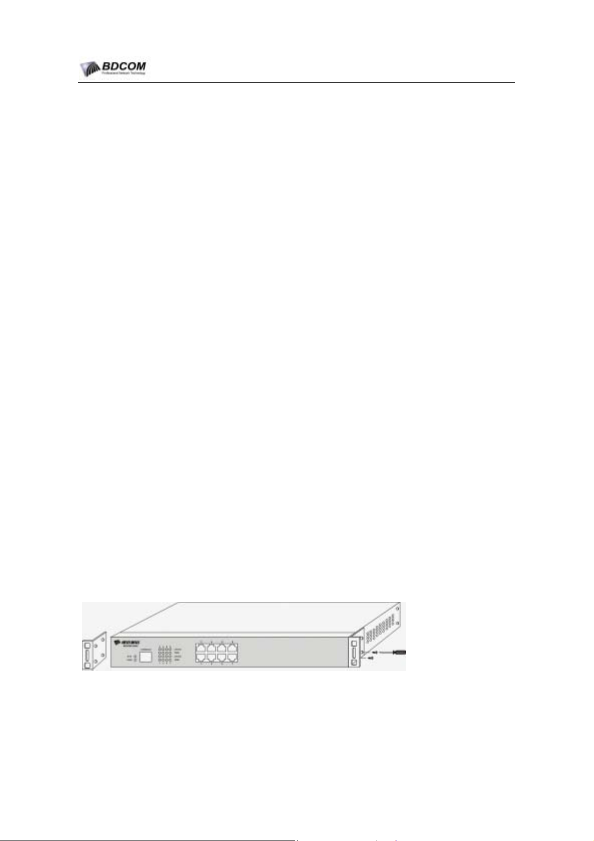
Switches are mounted on the mounting with brackets.Fixed the mounting and the switches face the
front.Operate follows:
Mount the switch after the brackets are fixed. Refer to the following illustration:
- 7 -
Page 10
BDCOM S2008 Switch Hardware Installation Guide
3.3 Connecting Console port
There is a console port on BDCOM S2008 switc h. This section explains the fea tures and usage of the
port.
Speed: 1200 bps-115200bps, standard RJ 45 plug. Use dedicated cable to connect the port to PC
parallel port. Use terminal software (such as Windows super terminal) to configure and monitor
operations. Cable is provided with host. Terminal parallel communication parameters can be set as:
baud rate 9600bps, 8-bit data, 1 stop bit, no parity bit.
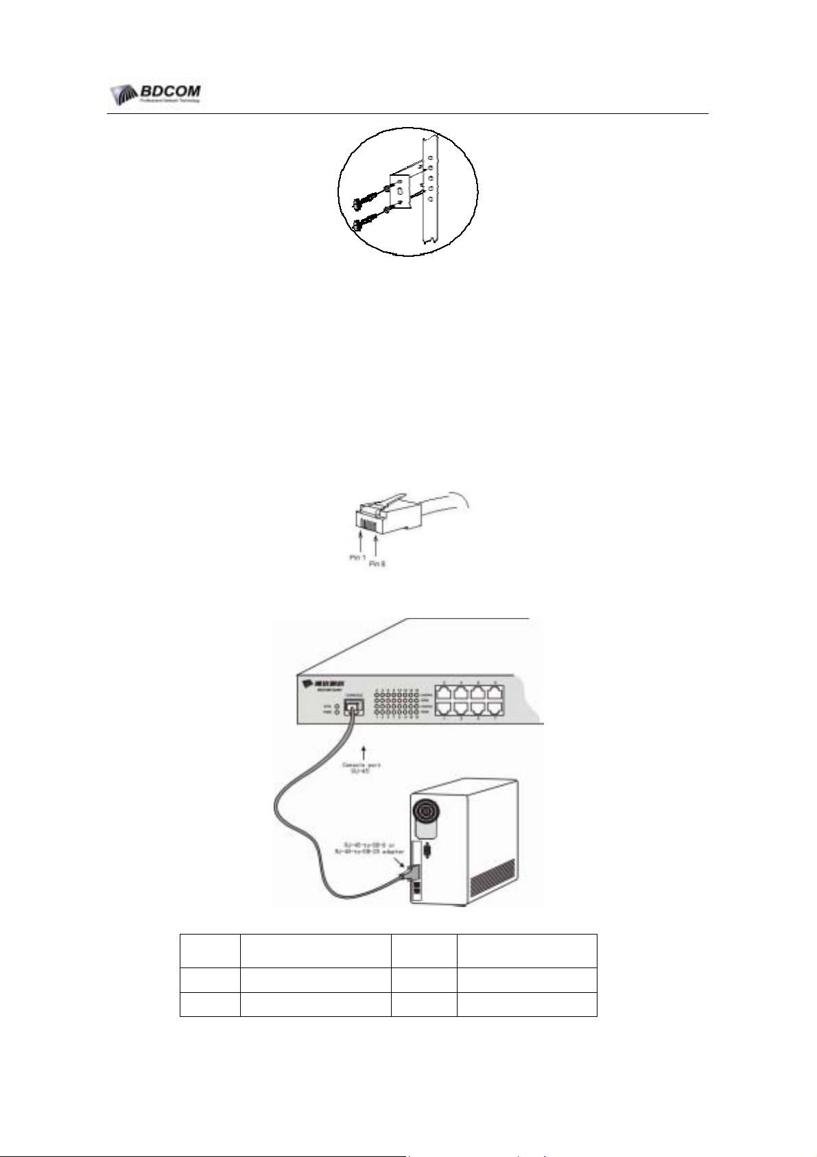
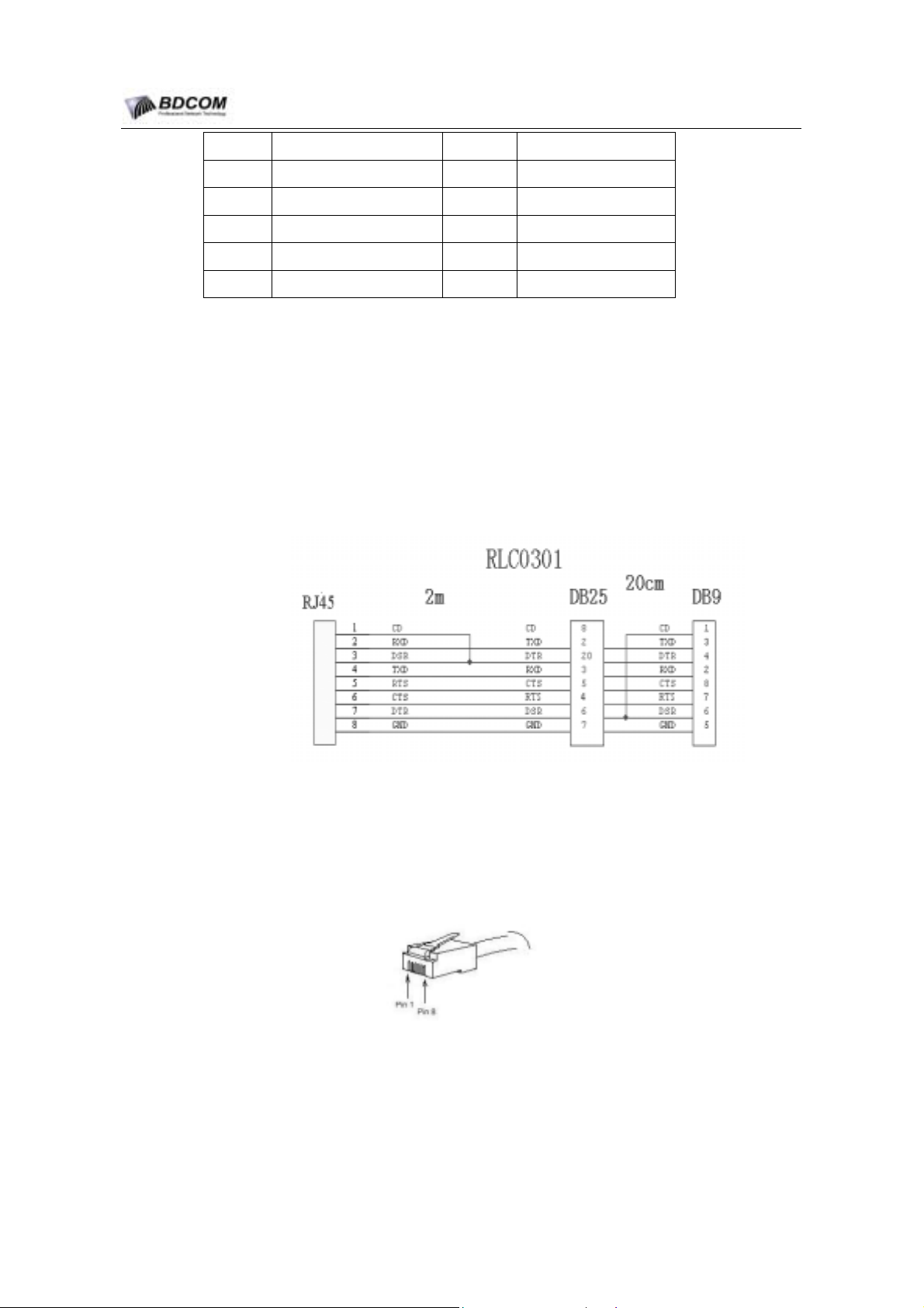
Console port uses RJ-45 connectors shown as follows. There are 8pin RJ-45 connectors.
BDCOM S2008 switch console port and computer connection:
Console port pins are as follows:
Pin No. Description Name Note
1 Carrier detect CD No connect
2 Received data RXD Input
- 8 -
Page 11
BDCOM S2008 Switch Hardware Installation Guide
3 Data set ready DSR No connect
4 Transmitted data TXD Output
5 request to send RTS No connect
6 clear to send CTS No connect
7 Data terminal ready DTR No connect
8 signal ground SG GND
Note:
S2008 switch Console Port does not support flow control. Therefore, “Data Flow Control” should be set
“No” while using super terminal to manage switch.
3.3.1 Console port connection
This cable is used to connect BDCOM S2008 switch console port to external terminal. One end is RJ45
8-pin plug. The other end are 25-hole (DB25) and 9 –hole (DB9) plugs. RJ45 connecter plugs into
BDCOM S2008 switch console port. Use DB25 and DB9 according to the terminal parallel port. The
side of the cable is shown as follows. The product No. of this cable is RLC0301.
3.4 Connecting Fast Ethernet Interface
BDCOM S2008switch provides 24 10/100Base-TX ports. Each port is embedded with 2 LEDs to
indicate the statues of Link/ACT and 10/100M. Use switchUTP to connect to other Ethernet terminals.
UTP no. and console no. are the same. Refer to the following chart..
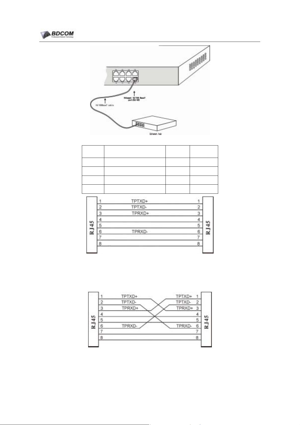
All of the 24 10/100Base-TX ports of BDCOM S2008 switch support auto-MDIX. Choose the
connection which best fits the connection between BDCOM S2008switch and Ethernet terminal.
10/100Base-TX port and other Ethernet terminal connection is shown as follows:
- 9 -
Page 12
BDCOM S2008 Switch Hardware Installation Guide
UTP port explaination is shown as follows:
Pin NO. Description Name Note
1 Dat a transmission positive TPTXD+ Output
2 Dat a transmission negative TPTXD- Output
3 Dat a r eceive positive TPRXD+ Input
6 Data receive negative TPRXD- Input
Figuer 3-1 Parallel connection UTP5
Note:
Cable connection and colors follow the regulations in EIA/TIA 568A.
Figuer 3-2 Cross connection UTP5
Note:
Cable colors follow the regulation in EIA/TIA 568A.
- 10 -
Page 13

BDCOM S2008 Switch Hardware Installation Guide
Chapter 4 Hardware Troubleshooting
4.1 Trouble analyzing
The key to troubleshooting is to separate trouble from the system. By analyzing what system should do
and what system is doing, troubleshooting becomes easy. Think of the following systems while
analyzing troubles:
18. Power and cooling system—Power and cooling fan;
19. Ports, cables and connections—ports on the front panel of the switch and
cables connected to the ports.
4.1.1 Power and cooling system breakdown
Examine the following conditions to separate troubles:
20. The power is “ON”. Make sure the cooling fan is working normally. If cooling
fan is not working normally, check the fan;
21. Examine the environment. The switch cannot be overheated. Make sue the
inhale and exhale hole of the switch is clean. Refer to “General
Requirement for Working Environment”. The temperature of the switch
working environment is 0-40 (32℃ -104
º
F
).
22. If switch is not working and “PWR” indicator is not light, check the power
supply.
4.1.2 Ports, cables and connections breakdown
To separate problems, check the follow status:
23. If switch port is unable to link, check the connection. Make sue the
connection is normal;
24. If the power is “ON”, check the power supply and power cord;
25. If the system is working but the console port is not, make sue the console
port configurations are as follows: 9600 baud rate, 8-bit data bit, no parity
bit, 1 stop bit and no flow control.
4.2 LEDs
LEDs indicates what switches are doing. BDCOM S2008 switch LED and functions are as follows:
NO. Name Description Note
1 PWR Power indicator lights Switch on and indicator lights.
2 SYS System Indicator
Indicator lights when the system is turning on.
Indicator blinks when the system is functioning.
3
Indicator embedded on
the left side of each
port.
Indicator lights when link status is normal.
Indicator blinks when data is being sent or
received.
- 11 -
Page 14

BDCOM S2008 Switch Hardware Installation Guide
Indicator lights when the port is in 100M data
transfer mode. Indicator dies out when the port is in
10M data transfer mode.
4
Indicator embedded on
the right side of each
port.
- 12 -
Page 15
BDCOM S2008 Switch Hardware Installation Guide
Chapter 5 Switch Maintenance
Warning:
1) Ensure static electricity emission of your body before openning the chassis.Please read
“Safety Notices” before any operating in appendixB after closing the switch..
Please unlatch power pin when operate near or on the Switch.
2)
5.1 Open the chassis
This section introduces how to open the chassis and the tools needed and operating methods.
Warning:
Do not touch the power supply to avoid any hurting when the power cord is connected.
It maybe need some tools which are not provided as the standard equipment with the Switch, as the
folllowing:
cross screw-driver;
Electrostatic discharge-pretective wrist strap.
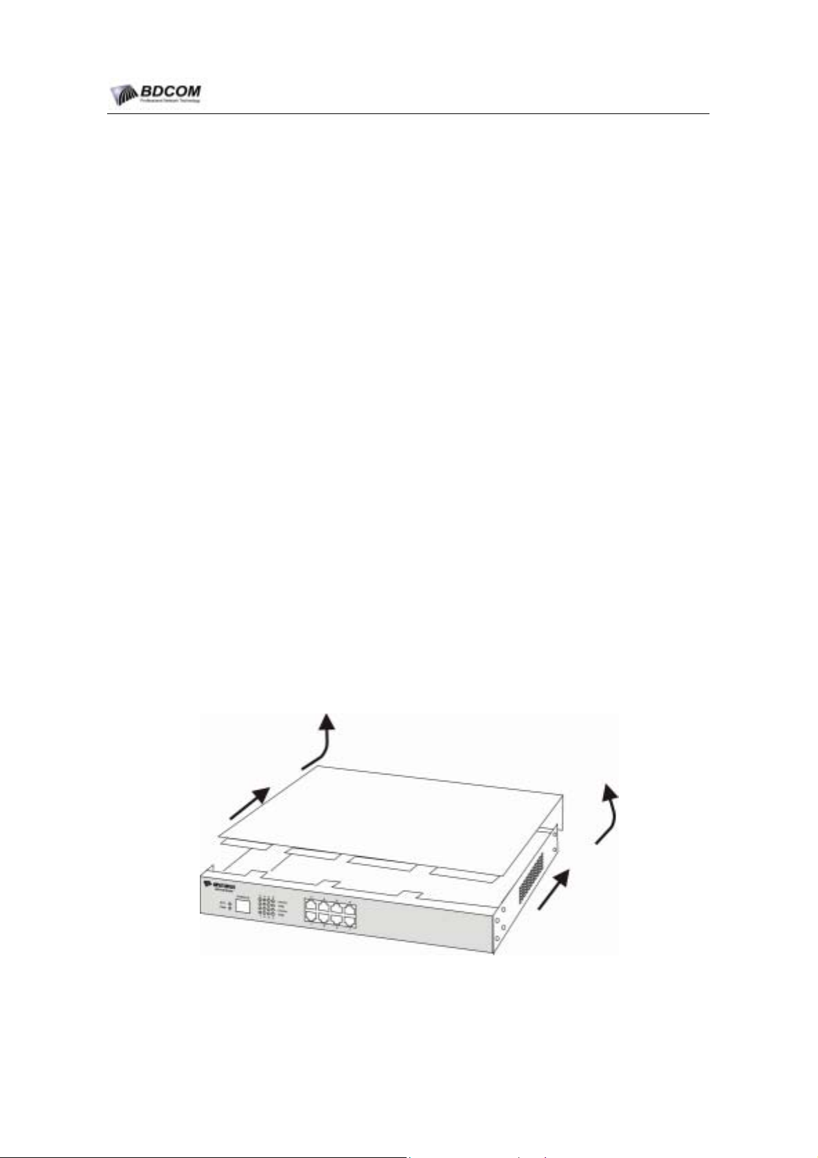
Opening the Switch top as the following steps
26. Close the power switch(press the switch to OFF side);
27. Disconnect all cables from the rear panel of the Sitch;
28. Drive off the screw on fixed top by screw-driver as figure 1 ;
Note:
The chassis is consist of the top and bottom.
29. Holding the chassis with both hands ,position it as shown in the following
figure.
:
Note:
30. When the top is off,set it aside and it shows the layout of system cards
- 13 -
Page 16
BDCOM S2008 Switch Hardware Installation Guide
Put down the top steady avoiding any demage after lifting it , otherwise it will be very difficult to install
later.
5.2 Close the chassis
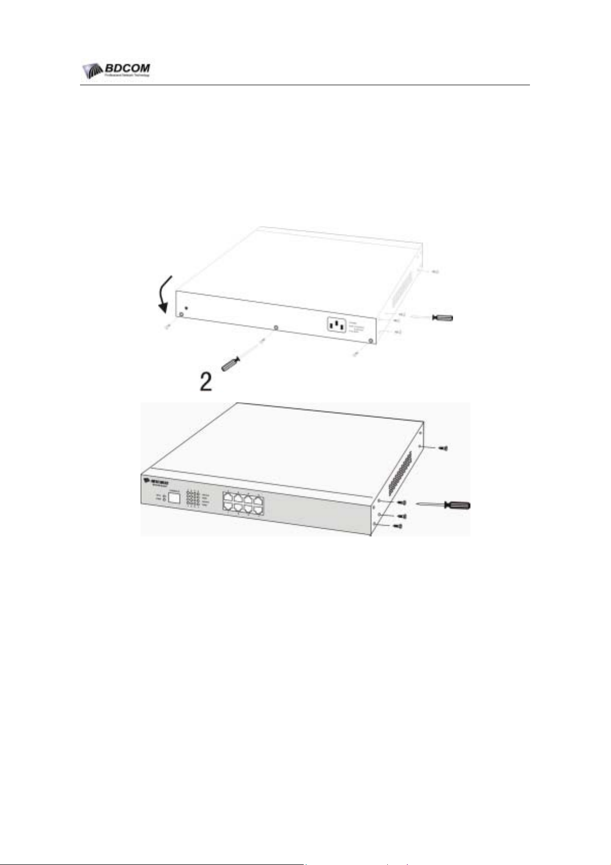
This section introduce the procession of locating the top and closing chassis .Please act as the following
procession:
31. As the following picture 1 , put the top and bottom well according to their
place;
32. Attach the edges of the top and the bottom according to the picture 1;
33. When the two sections are together, slide the top setion into the slots on the
front panel of the bottom to make sure the following:
The top section fits into the bottom section .The bottom section fits into the front of the top
section.
Each side of the top and bottom sectionfits together.
34. Replace and tighten the top screws by the screw-driver as picture 2;
35. Reset the chassis of the Switch on a desktop or in a rack;
36. Connect all cables after completing all work.
- 14 -
 Loading...