

Page 1
R
专
业
网 络
科
技
User Guide
100M PoE Switch
S1010-8P-120/S1006-4P-65
.
Page 2
Disclaimer
Please note that the manual is for reference only. It does not cons
tute a legal contract or a commitment between
BDCOM and any person or en
ty. Although ever y effor t has been made to ensure all the informa on is
correct ,inaccuracies or typographical errors may s
occur. In no event shall BDCOM be responsible or liable, directly or
indirectly, for any damage or loss caused or alleged to be caused by or in connec
on with the manual.
BDCOM reser ves the right to alter, update and other wise change the informa
on contained in the manual from me to
me without no e.
Introduction
Overview
S1010-8P-120/S1006-4P-65 are Power Over Ethernet switch. The PoE por ts can automa ally detect and
supply power with those IEEE 802.3af/at compliant Powered Devices (PD). The power is transmi
ed along with
data by one single cable allowing you to expand your network where there are no power lines or outlets and
which allow you to expand devices such as AP, IP Cameras or IP Phones, etc.
The PoE Switch have VLAN func
on that improve the network environment and reduces network maintenance
costs.
Port Feature
Model
10/100Mbps RJ45 Port
PoE Port
PoE Standard
S1010-8P-120
10
Port1~8
IEEE802.3af/at
S1006-4P-65
6
Port1~4
Product Appearance
Front panel
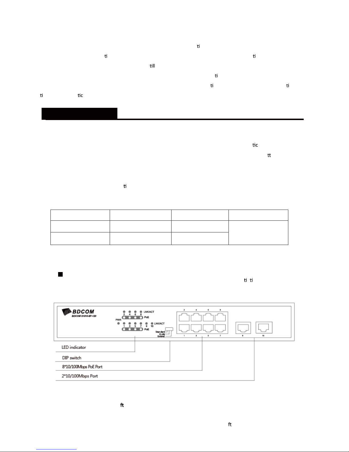
The Front Panel of the S1010-8P-120 consists of 10-Por t 10/100M Auto-Nego
a on Ethernet R
J45 Por t. The LED indicators are also on located on the panel.
DIP Switch
The DIP switch in located in the le panel.
Standard: the factory default mode, can normally communicate between port 1~10.
VLAN: 1-8 port can be isolated each other, but 1-8 port can connect to 9/10 port a
er open VLAN model to stop
broadcast storm Which can increase forwarding rate of frame.
1
Page 3
Extend: Up to 250m PoE distance.it allows you to expand you network via Ethernet cable to where there is no power
Line or outlet but where you want to fix device such as IP Cameras.
LED indicator
LED Color Func
on
PWR
Green
Off: No Power supply.
Light: Indicates the switch has power.
LNK/ACT Green
Off: No device is connected to the corresponding port.
Light: Indicates the link through that port is successfully
Established at 10/100Mbps.
Blink: Indicates that the Switch is ac
vely sending or
Receiving data over that port.
PoE Orange
Off: No PoE powered device (PD) connected.
Light: There is a PoE PD connected to be port, which
Supply power successfully.
Blink: Indicates port abnormal power supply.
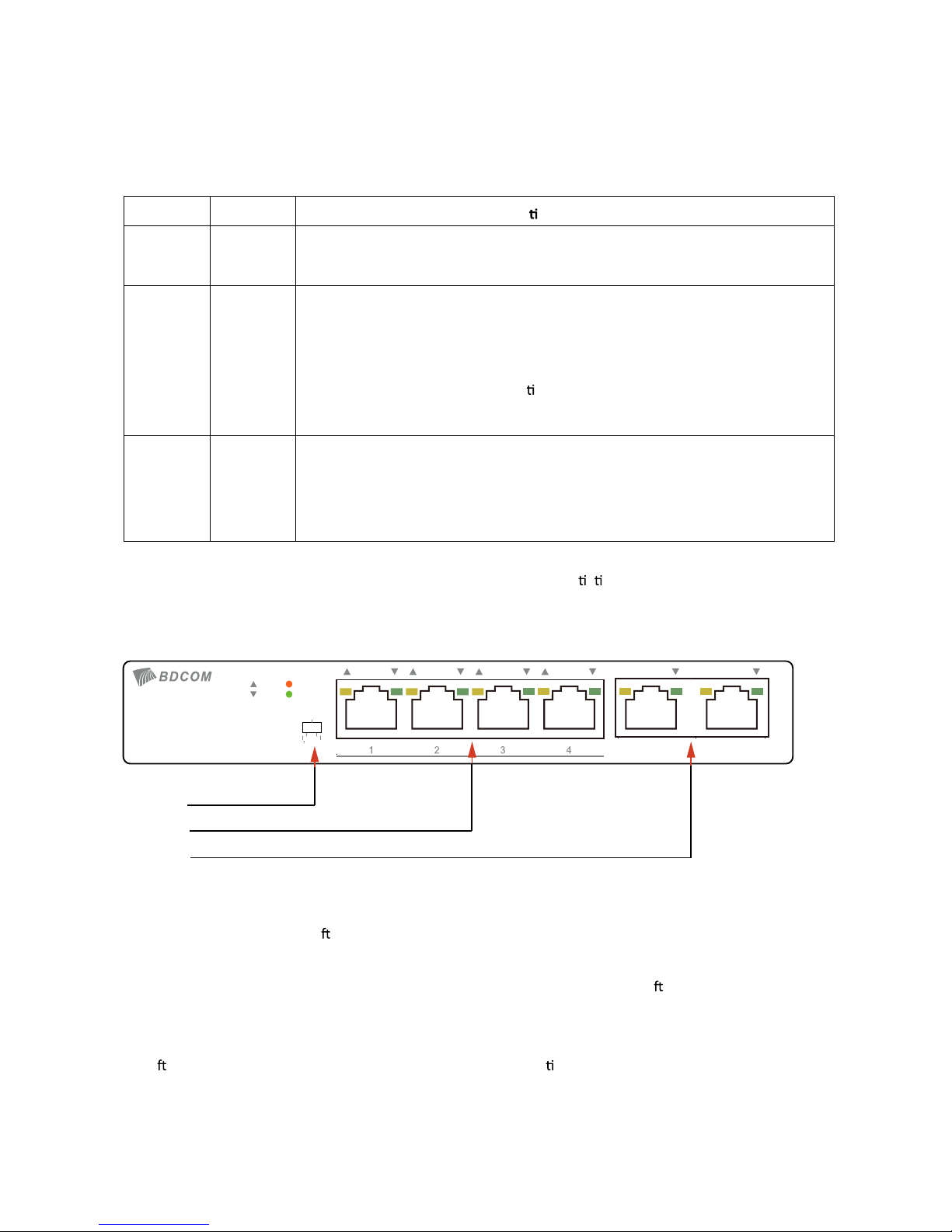
The Front Panel of the S1006-4P-65 consists of 6-Por t 10/100M Auto-Nego a on Ethernet R J45 Por ts, The LED
indicators also on located on the panel.
DIP Switch
The DIP switch is located in the le panel.
Default mode: when open default mode ,the poe switch can normally communicate between port 1~6
CCTV mode: 1-4 port can be isolated each other .but 1-4 port can connect to 5, 6 port a
er open CCTV to stop
broadcast storm which can increase forwarding rate of frame. The CCTV mode, allows you to expand you network via
Ethernet cable to where no power line or outlet .
Note: A
er change the mode, in order to the corresponding configura on take effect.the PoE switch need to restart
manually restart the PoE switch.
2
5 6
PoE
4*10/100Mbps PoE Port
2*10/100Mbps Port
CCTV
OFF
ON
PoE
DATA
10/100M
BDCOM S1006-4P-65
DIP Switch
Power
Page 4
LED indicator
LED
Color
Func on
PWR Orange
Off: No Power supply.
Light: Indicates the switch has power.
DATA Green
Off: No device is connected to the corresponding port.
Light: Indicates the link through that port is successfully
established at 10/100Mbps.
Blink: Indicates that the Switch is ac
vely sending or
receiving data over that port.
PoE Orange
Off: No PoE powered device (PD) connected.
Light: There is a PoE PD connected to be port, which
supply power successfully.
Blink: Indicates port abnormal power supply.
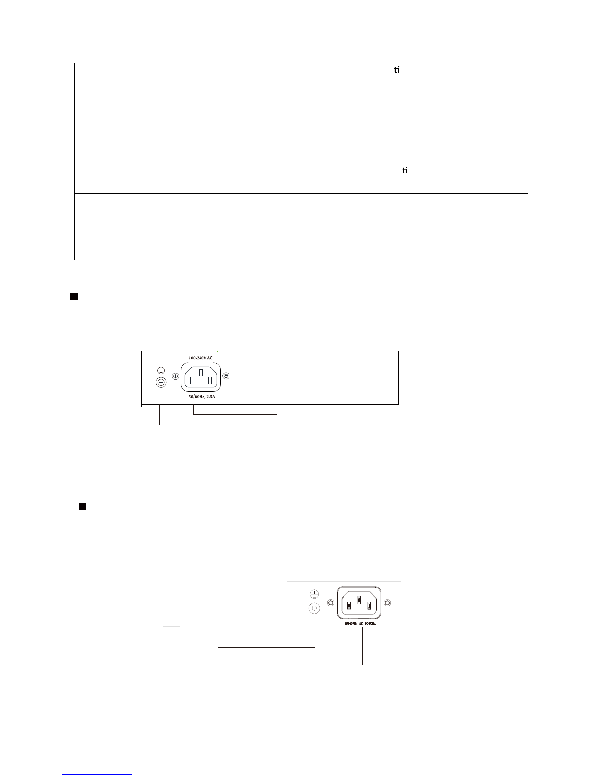
The rear panel of S1010-8P-120 indicates AC inlet power socket .
Rear Panel
The rear panel of S1006-4P-65 indicates AC inlet power socket .
3
Grounding Column
Power Socket
max
Power Socket
Grounding Column
Rear Panel
Page 5
Power socket
Connect the female connector of the power cord here, and the male connector
to the AC (Alterna
g Current) power outlet. Please make sure the voltage of
the power supply meets the requirement of the input voltage
Grounding
The switch already comes with lightning protec
on mechanism. You can
also ground the switch through the PE (Protec
g Earth) cable of AC cord
or with Ground Cable.
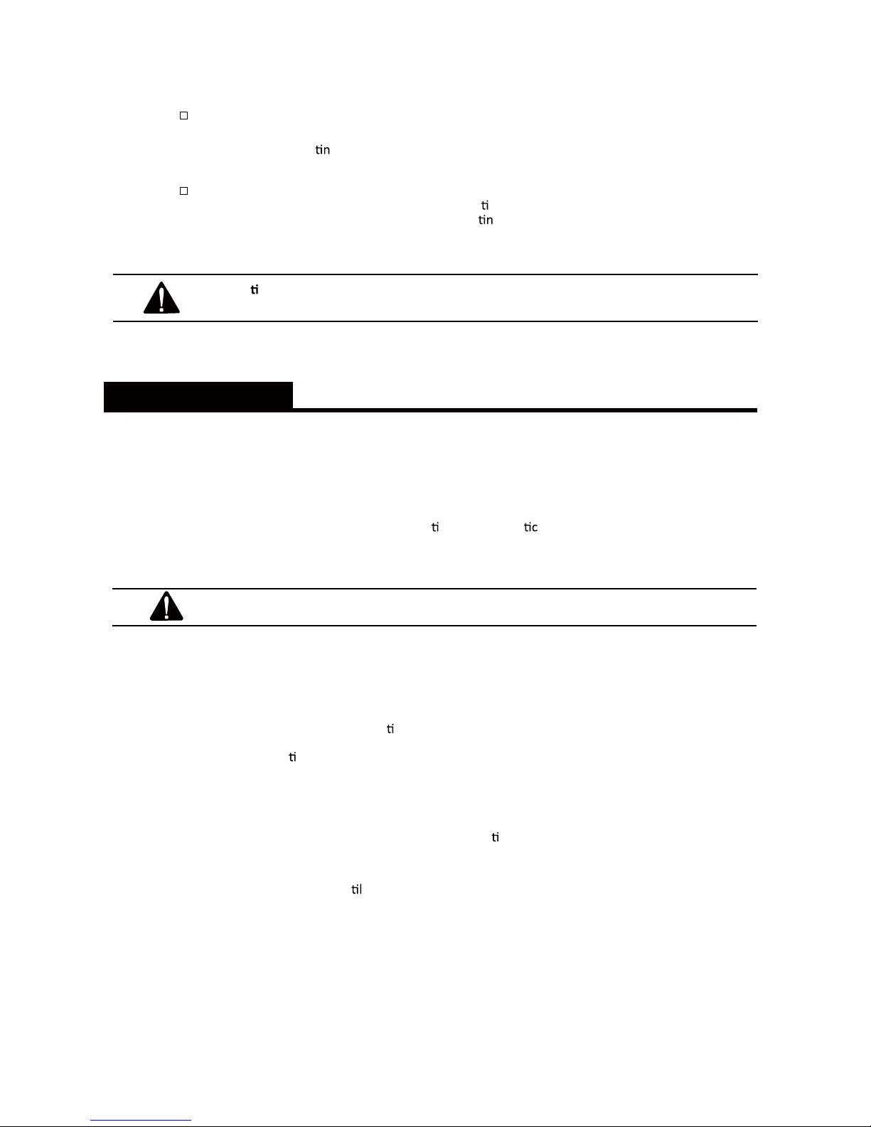
Cau on: Please use the provided power cord.
Make sure the power socket has a good contact with the ground.
Installation
Package Contents
▄ PoE Switch. ........................................ 1
▄ Power Cord....... ................................. 1
▄ User Guide. ....................................... 1
▄ Accessories(Rack angle iron*2, Rack installa
on bolt*8, plas cushion*4)
Caution: If any part is lost and damaged, please contact your local agent immediately.
Safety Precautions
To avoid any device damage and bodily injury caused by improper use, please observe the following
rules.
▄ Keep the power off during the installa
on.
▄ Wear an ESD-preven
ve wrist strap, and make sure that the wrist strap has a good skin contact
and is well grounded.
▄ Use only the power cord provided with the switch.
▄ Make sure that the supply voltage matches the specifica
ons indicated on the rear panel of the
switch.
▄ Ensure the vent hole is well ven
ated and unblocked.
▄ Do not open or remove the cover of the switch.
▄ Before cleaning the device, cut off the power supply. Do not clean it by the waterish cloth, and
never use any other liquid cleaning method.
4
Page 6
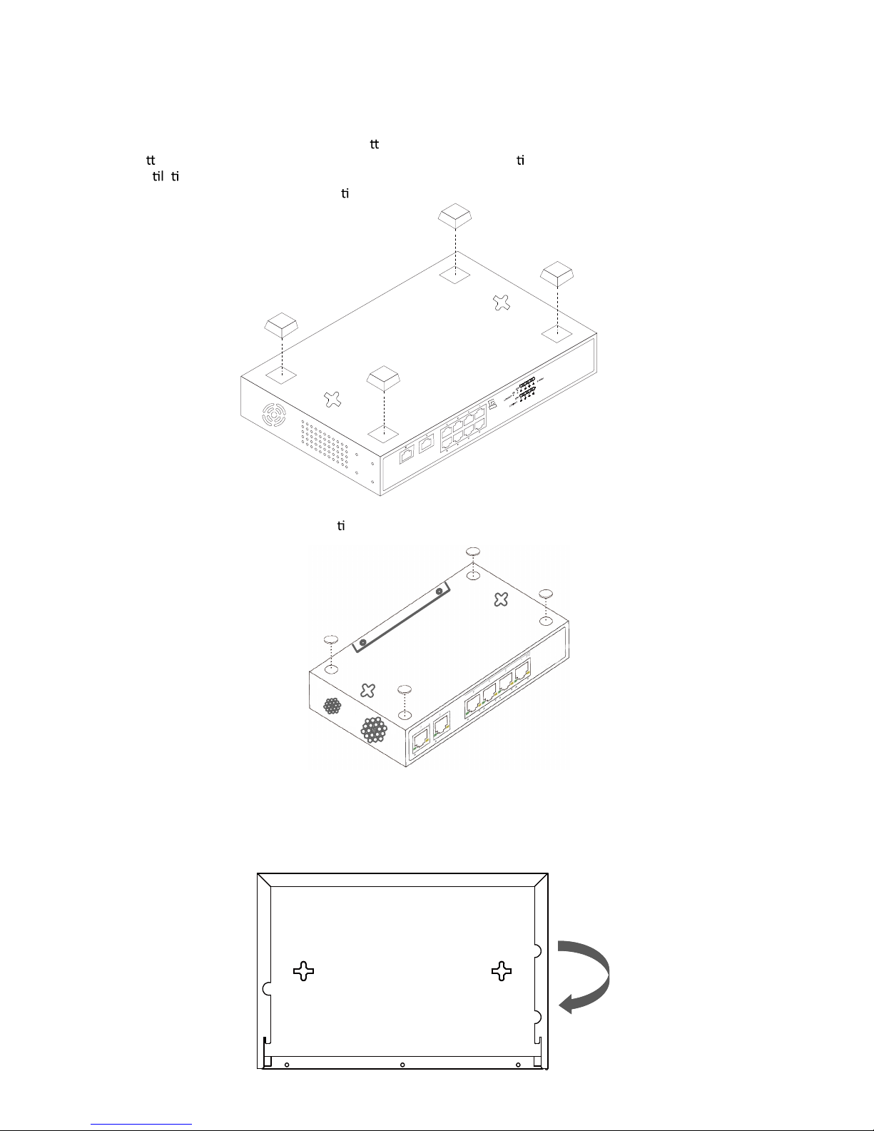
Desktop Installation
Install the Switch on a desktop, please a ach these cushioning rubber feet provided on the
bo
om at each corner of the Switch in case of the external vibra on. Allow adequate space for
ven
a on between the device and the objects around it.
The S1010-8P-120 Desktop Installa
on
The S1006-4P-65 Desktop Installa on
Wall-mounted installation
In the first two fixed screw on the wall as shown in the figure below
Aim at the two fixed hole switches, and the machine smoothly on the screw
( S1010-8P-120)
Default
VLAN
CCTV
5
Page 7
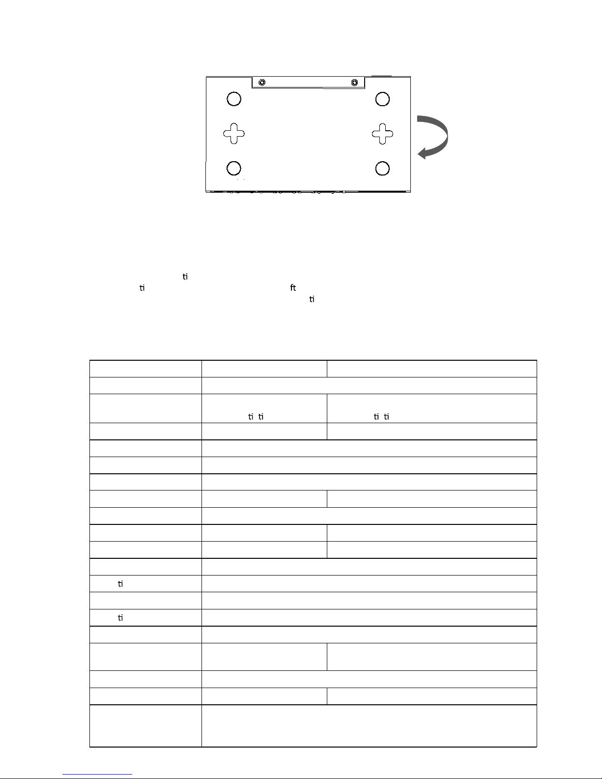
( S1006-4P-65)
Turn on the switch
Plug in the nega ve connector of the provided power cord into the power socket of the device,
and the posi
ve connector into a power outlet . A er the device is powered on, it begins the Power-
On Self-Test. The PWR LED indicator will light on all the
me.
Appendix
Specification
Model S1010-8P-120 S1006-4P-65
Standard IEEE802.3, IEEE802.3u, IEEE802.3az, IEEE802.3x, IEEE802.3af, IEEE802.3at
Port 10*10/100Mbps
Auto-Nego a on RJ45 Port
6*10/100Mbps
Auto-Nego a on RJ45 Port
PoE Port Port1~8 Port1~4
PoE Power Output 32W Max
PoE Power on RJ-45 Mode A 1/2(+) 3/6(-)
VLAN and CCTV Support
PoE total 120W 60 W
Forwarding Mode Storage-and-Forward
Switching Capacity 2G 1.2 G
Forwarding Rate 1.488Mpps 0.89Mpps
Input Power Supply AC 100-240V 50/60Hz
Opera on Temperature 0 ℃ ~40℃
Storage Temperature -40 ℃ ~70℃
Opera on Humidity 10%~90%RH non-condensing
Storage Humidity 5%~90%RH non-condensing
MAC Address Table 8K, Auto-learning, Auto-aging 2K, Auto-learning, Auto-aging
Fan Fanless
Dimensions(L*W*H) 220*150*44mm 160*93*32mm
Network Media(cable)
10BASE-T: UTP category 3,4,5 cable (≤100m)
100BASE-TX: UTP category 5 cable (≤100m)
100BASE-FX:MMF,SMF
6
Page 8

上海博达数据通信有限 公司
Shang hai B aud Data Communi catio n Co., LTD.
网址 Web: www. bdco m.co m.cn
地址 Add: 上海浦东 张江高科技 园区居里 路 123 号
N o .123, Jul i Road ,Pud ong Zhang jiang Hig h-Tech Park, Shangha i
邮编 Zip Code: 201203
7
 Loading...