

Page 1

1705 Router
Web Configuration Manual
Page 2

Content
Content
Chapter 1 The use of CMS................................................................................................................................................... 1
1.1 The network setting ............................................................................................................................................... 1
1.2 Configuration guide ...............................................................................................................................................4
1.2.1 Startup and logging in ...............................................................................................................................4
1.3 First page .............................................................................................................................................................. 5
1.3.1 Typical setting............................................................................................................................................ 6
1.3.2 Wizard setting............................................................................................................................................ 6
1.3.3 Advanced setting .......................................................................................................................................8
1.4 The explanation of advanced setting..................................................................................................................... 8
1.4.1 WAN Port Configuration............................................................................................................................ 8
1.4.2 LAN Port Configuration ...........................................................................................................................10
1.4.3 NAT Configuration................................................................................................................................... 11
1.4.4 DHCP server configuration...................................................................................................................... 13
1.4.5 DNS Configuration ..................................................................................................................................14
1.5 Advanced............................................................................................................................................................. 14
1.5.1 Multiplex Line ..........................................................................................................................................15
1.5.2 Port Mapping........................................................................................................................................... 16
1.5.3 Special Address Mapping........................................................................................................................ 17
1.5.4 Firewall.................................................................................................................................................... 17
1.5.5 Default Route ..........................................................................................................................................18
1.5.6 Static Route............................................................................................................................................. 19
1.5.7 DDNS Settings ........................................................................................................................................ 20
1.5.8 VPN Settings........................................................................................................................................... 21
1.6 Admin tools ..........................................................................................................................................................22
1.6.1 User Management................................................................................................................................... 22
1.6.2 Config Files .............................................................................................................................................24
1.6.3 IOS Software........................................................................................................................................... 24
1.6.4 Time Settings .......................................................................................................................................... 25
1.6.5 Remote Control ....................................................................................................................................... 26
1.6.6 Diagnose Tool.......................................................................................................................................... 26
1.6.7 Port Define ..............................................................................................................................................27
1.6.8 System Reboot........................................................................................................................................ 27
1.7 Running State...................................................................................................................................................... 27
1.7.1 System Information .................................................................................................................................28
1.7.2 System State........................................................................................................................................... 28
1.7.3 System Log .............................................................................................................................................28
- I -
Page 3

1705Router Web Configuration Manual
Chapter 1 The use of CMS
Before configuring the router, please ensure that your computer is installed necessary
softwares(for example: Windows 95/98/ME/NT2000/XP), and configure the netwok in
reason. If you don’t know how to configure network, please read the setting explanation
of next section ”Configure network”. If you have already configured network correctly,
you can leap over next section and refer to “Configuration guide” directly.
Note:
1) This configuration method(configure router by Web page layout) is suitable for primary technical
personnel, but we recommend telnet mode to configure router for intermediate or senior technical
personnel. You should avoid by all means using web and telnet at one time to config router.
2) When you use web to config 1705, You should renovate the page layout after configuring 1705
completely in order to show the correct result.
3) If you use web to config 1705, we suggest that you ues Microsoft IE browser 6.0 or high-edition,
and use 1024*768 screen area.
1.1 The network setting
The default interface of 1705 is TP2, and the default IP address of TP2 is 192.168.2.1,
the default subnet mask is 255.255.255.0. These parameters can be altered for need,
and they are default value in the following character. The material step for setting
network is shown as following (take example for Windows 2000):
Step 1: Connect your computer to the fast Ethernet port TP2 of 1705 router.
Step 2: Setting the IP address of this computer.
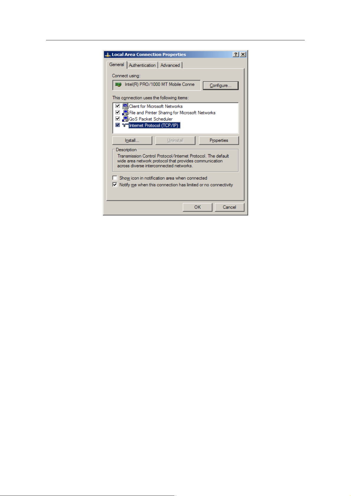
(1) Beginning->control panel->network and dialing connection
(2) Use the right key to click”network connections”, then click”property”menu.
(3) Pitch on”Internet protocol(TCP/IP)”. The figure is following:
- 1 -
Page 4
1705Router Web Configuration Manual
(4) Click”property”keystoke and set IP address of the computer.
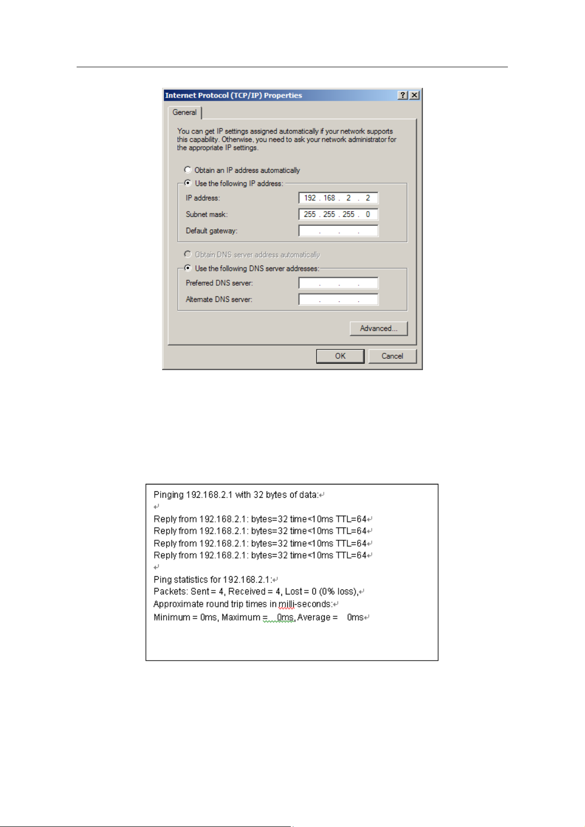
(5) In the dialog box of “Internet protocol(TCP/IP) property”, pitch on”use the
following IP address”. Infilling 192.168.2.xxx in”IP address”(the range of xxx is
2~254). Infilling 255.255.255.0 in”subnet mask”. Infilling 192.168.2.1 in”default
gateway”(that is the default IP address of 1705 router).
Note:
Because the default IP address of 1705 router is 192.168.2.1, xxx can’t be filled in 1.
As the following figure show:
- 2 -
Page 5
1705Router Web Configuration Manual
(6) Click”confirmation” and complete configuration.
Step 3: Test the connection capability for computer and router.
(1) Beginning->running->key in”cmd”->confirmation
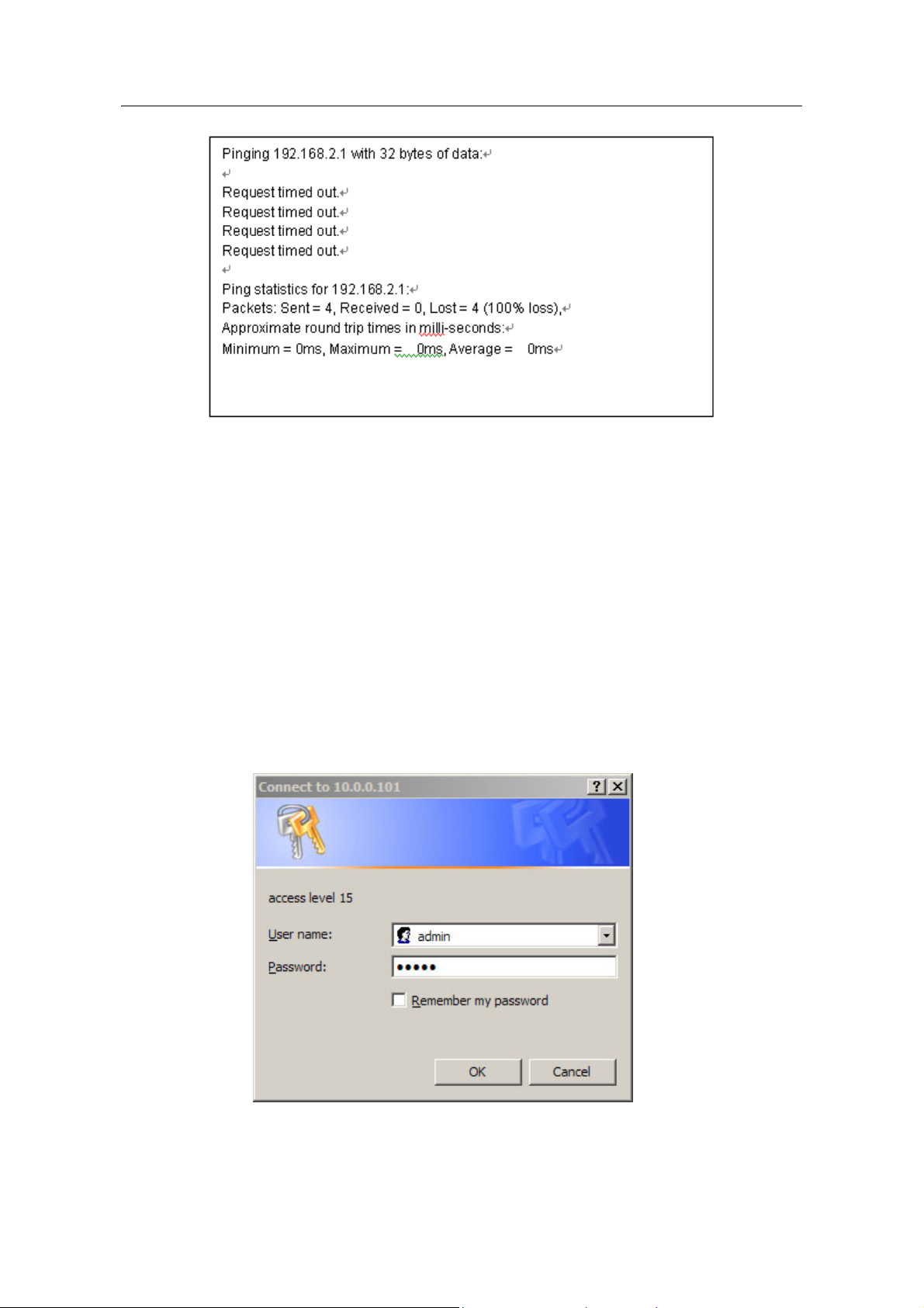
(2) In command prompt use “ping” command to test the connection capability,
perform”ping 192.168.2.1”:
If shows:
That shows the connection is successful.
If shows:
- 3 -
Page 6
1705Router Web Configuration Manual
That shows the connection is unsuccessful.
You can check the following points:
The indicator light which is joined computer port is bright or not. If the light
isn’t bright, that shows the connection is abnormality on physical. You can
change a line.
Check the TCP/IP setting is correct or not.
1.2 Configuration guide
If the connection of computer and 1705router is normal, you can configure the router by
Web browser(for example: Internet Explorer).
1.2.1 Startup and logging in
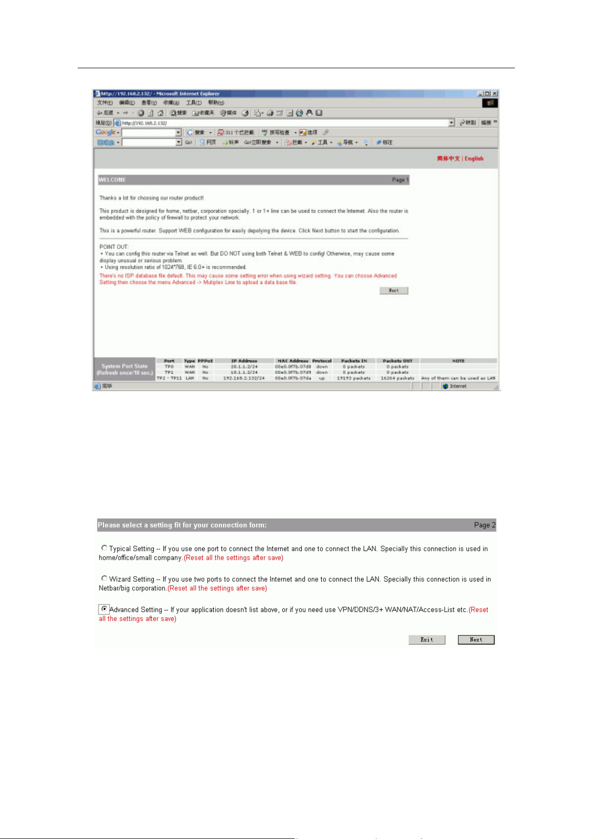
Open Internet Explorer browser, input http://192.168.2.1 in address blank and press
“enter”, as the following figure show:
Input right user name and password, then login(the default user name is admin,
password is admin).
Browser will show the material configuration page layout after login successfully.
- 4 -
Page 7
1705Router Web Configuration Manual
1.3 First page
Click “next” to begin configuring.
First the system will check router to ensure that whether it has been configured already
or not. If there is configuration in router, system will show a list to show the configuration.
Click “exit” to return the first page, click “return” to config router again.
If the router is default configuration, it will show the following layout page:
You can choose one configuration method.
- 5 -
Page 8
1705Router Web Configuration Manual
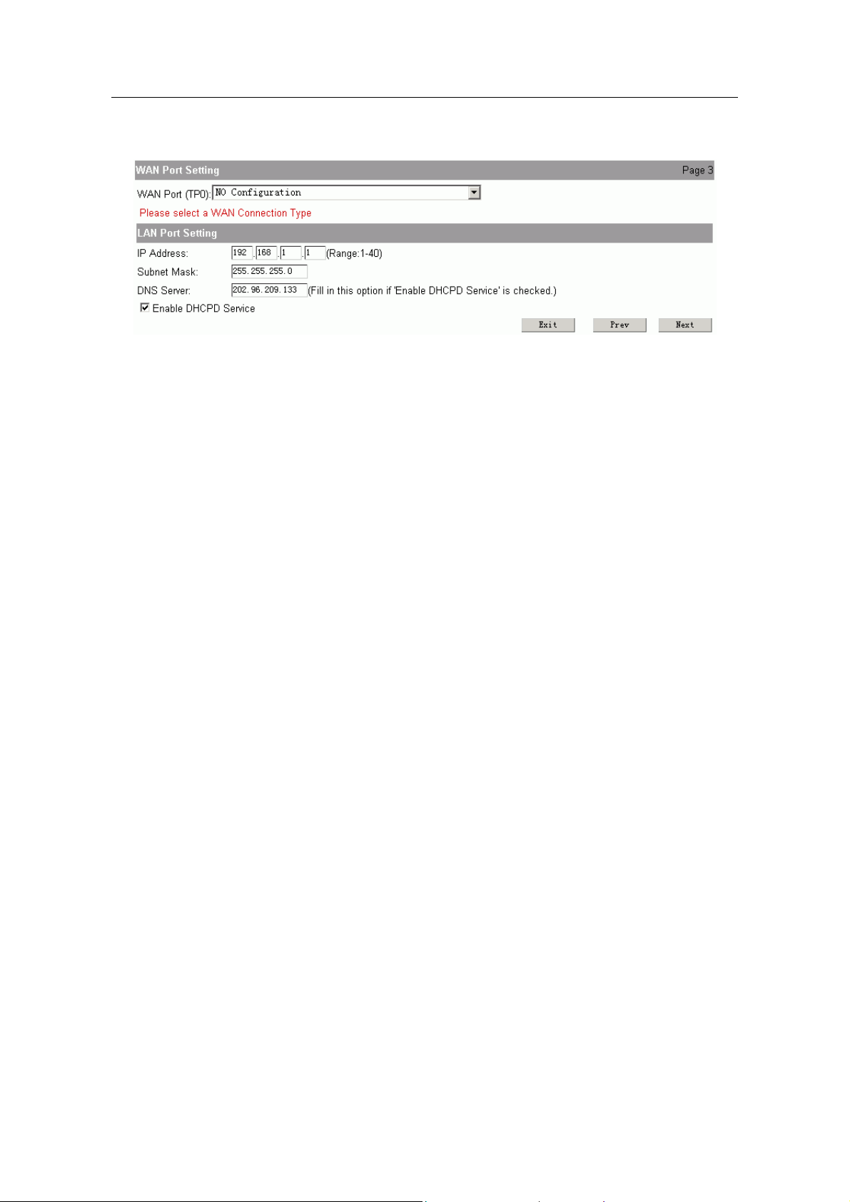
1.3.1 Typical setting
You should config two parts of content in typical setting:
WAN Port Setting:
connection methods to choose:
Typical setting 1: Using static IP on WAN port
IP address: fill in the IP address obtained from ISP.
Subnet mask: fill in the subnet mask obtained from ISP.
Default route: fill in the default gateway obtained from ISP.
DNS server and secondary DNS server: fill in the DNS address obtained
from ISP.
Typical setting 2: Using PPPoE on WAN port
Username: fill in the username obtained from ISP.
Password: fill in the password obtained from ISP.
Typical setting 3: Using dynamic IP on WAN port.
It isn’t need to do any setting in this method.
LAN port setting:
IP address: fill in the ip address of LAN port.
Note:
The range of last parameter is 1~40. And this IP address must be in the same net-segment with
LAN. User couldn’t use 192.168.2.1, because it is the reserved address, PC in LAN can logging
on router to config by 192.168.2.1.
that is configuring interface for connecting Internet. There are three
that is configing interface for connecting LAN.
DNS server: fill in the ip address of DNS server, the default is 202.96.209.133.
Enable DHCPD service: the default is enable. It is used to config IP address and
other parameters automatically. Don’t choose if you config manually.
Click “next” to show the configuration result, click “save and reboot” to finish
configuration and reboot the router.
1.3.2 Wizard setting
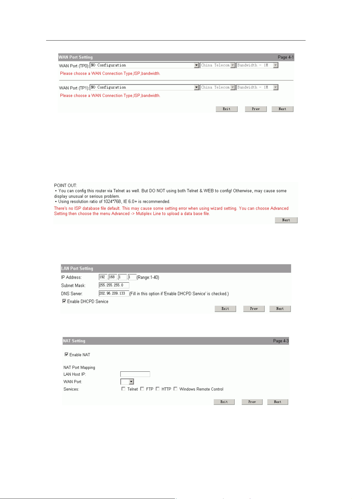
There are three steps to finish wizard setting.
WAN Port Setting: configure the port of connecting Internet.
- 6 -
Page 9
1705Router Web Configuration Manual
It is similar with WAN port setting of chapter 1.3.1, but it can configure one or two
ports. You can refer to chapter 1.3.1 to configure the parameter.
If you use two ports to connect Internet, you should configure the parameter of
ISP and bandwidth.
Note:
ISP chosen is used to make the configuration high-efficient in mutiplex line. We provide a
file named “isp_db” in order to achieve the configuration result( it is in router when leave
factory ). But this file isn’t necessary. If the system show the following page when you
logging on router:
It is show that the file named “isp_db” is lost. You can do follow this: Advanced
setting->Mutiplex line, to upgrade this file. ( Refer to chapter 1.5.1)
LAN Port Setting: configure the parameter of port for connecting LAN.
NAT Setting: Configure NAT.
Note:
If you don’t know how to configure, please use the default configuration and click “next”.
Enable NAT: The default is enable. Enable NAT in order to make PC connect
Internet.
- 7 -
Page 10
1705Router Web Configuration Manual
NAT Port Mapping: It can open the some port(such as TP0) in order to make
outside network accessing the router.
LAN Host IP: fill in the IP address of host.
WAN Port: select a port which is connected Internet( It is physical port).
Services: select these services in order to make outside-network host accessing.
Click “next” to show the configuration result, click “save and reboot” to finish
configuration and reboot the router.
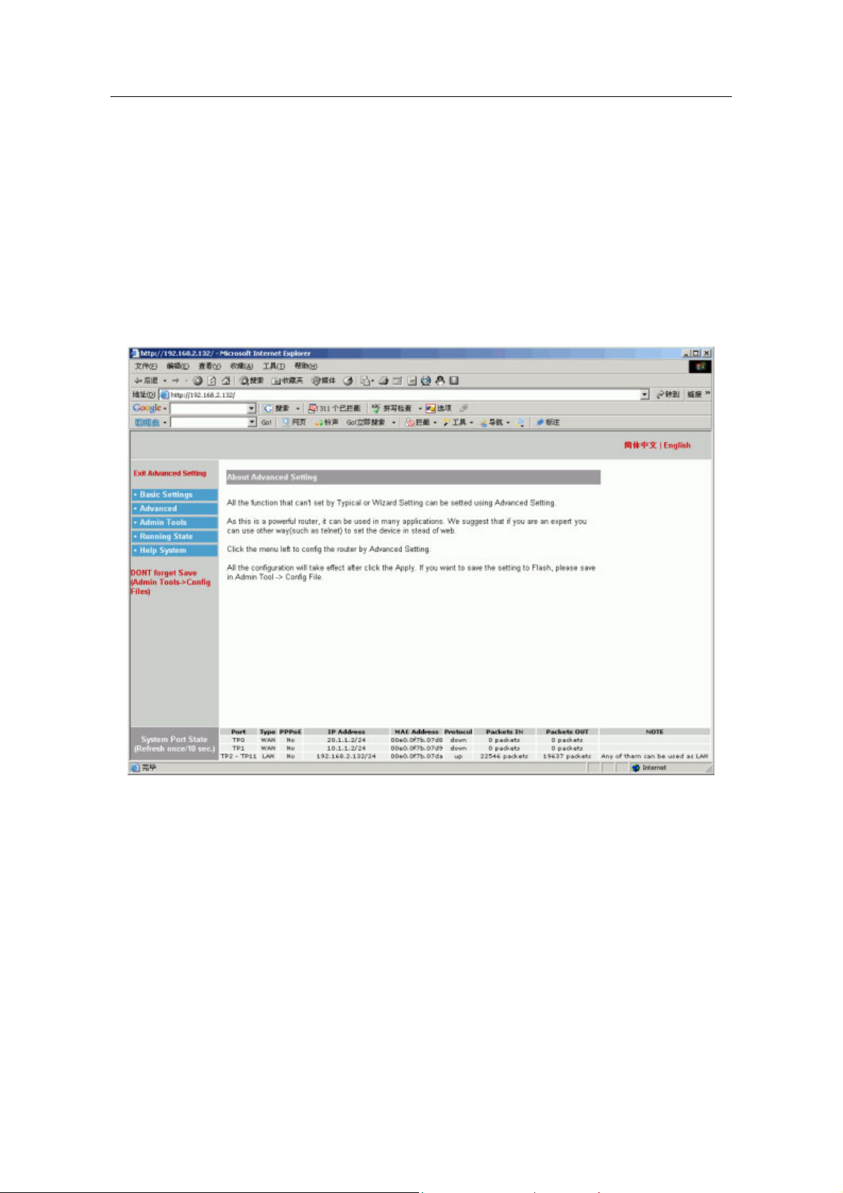
1.3.3 Advanced setting
If above two configuration can’t meet your need, you can use advanced setting. Enter
the page layout of advanced setting, the show is following:
1.4 The explanation of advanced setting
The basic configuration menu includes: WAN port configuration, LAN port configuration,
NAT configuration, DHCP server configuration, DNS configuration. The router can
connect Internet when it is finished basic configuration.
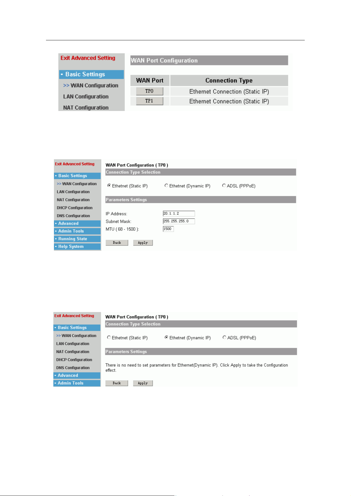
1.4.1 WAN Port Configuration
Users can configure WAN port to connect Internet. The configuration page layout is
following:
- 8 -
Page 11
1705Router Web Configuration Manual
It shows WAN port name and type(such as PPPoE, Static IP, dynamic IP) of router.
Click the button of port name to enter material configuration page layout.
There are three configuration types for WAN port:
Ethernet(static IP)
If you use the IP address which is provided by ISP, you should choose this
method to configure router
IP address, subnet mask: fill in the IP address and subnet mask that are provided
by ISP.
MTU(Maximum Transmission Unit): the default is 1500. It isn’t amended usually.
Ethernet(Dynamic IP)
If you obtain IP address automatically from ISP, you should choose this method.
And you needn’t configure any parameter.
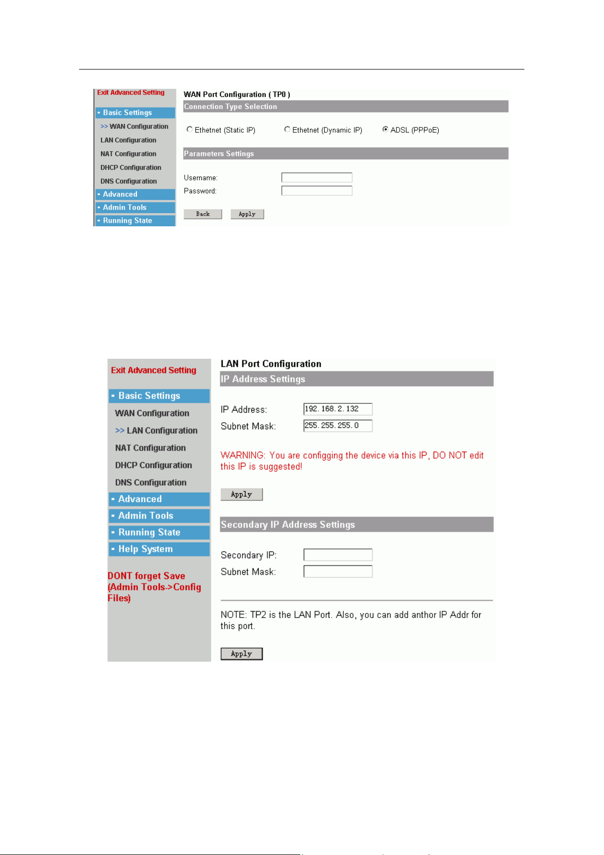
ADSL(PPPoE)
- 9 -
Page 12
1705Router Web Configuration Manual
If you use ADSL dialing to browse Internet, you should choose this method.
Username, password: fill in the username and password that is provided by ISP.
Click “apply” to make configuration effective, click “back” to keep old configuration.
1.4.2 LAN Port Configuration
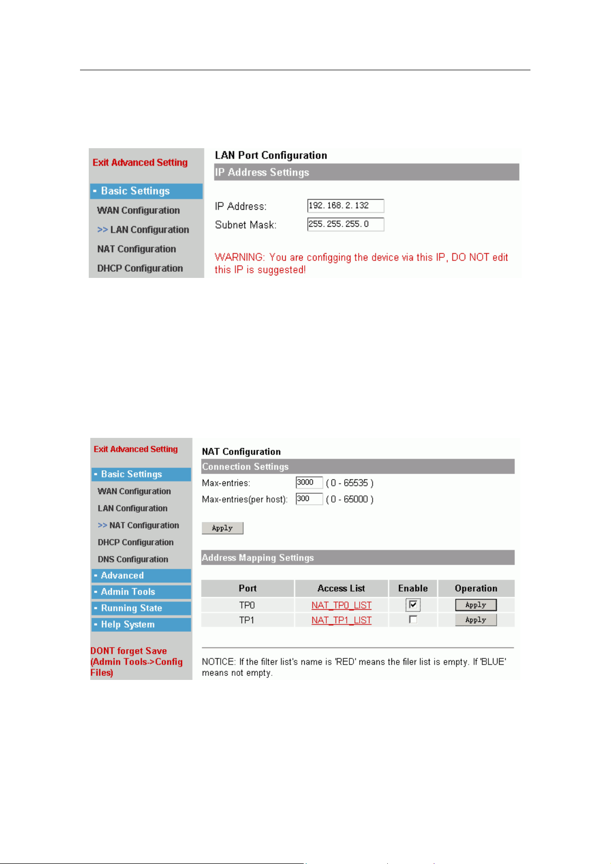
Users can configure LAN port to connect LAN. The configuration page layout is
following:
IP Address Settings:
IP address, subnet mask: fill in the IP address and subnet mask. The IP address
should be in the same net-segment with LAN.
Secondary IP address Settings:
The port can be filled in another IP address.
- 10 -
Page 13
1705Router Web Configuration Manual
Secondary IP address, subnet mask: fill in the IP address and subnet mask.
Note:
If the system shows the following information:
It is warning: you are configuring the router through this port, and you couldn’t alter this IP address. If you
click “apply” button to alter this IP address, system will disconnect with Web and you will not configure the
router.
1.4.3 NAT Configuration
What is called NAT, that is Network Address Translation. Its essence is that alter the
source IP address of data-packets which pass through router, in order to make more
users share one public ip address, or open Web service and FTP service in LAN.
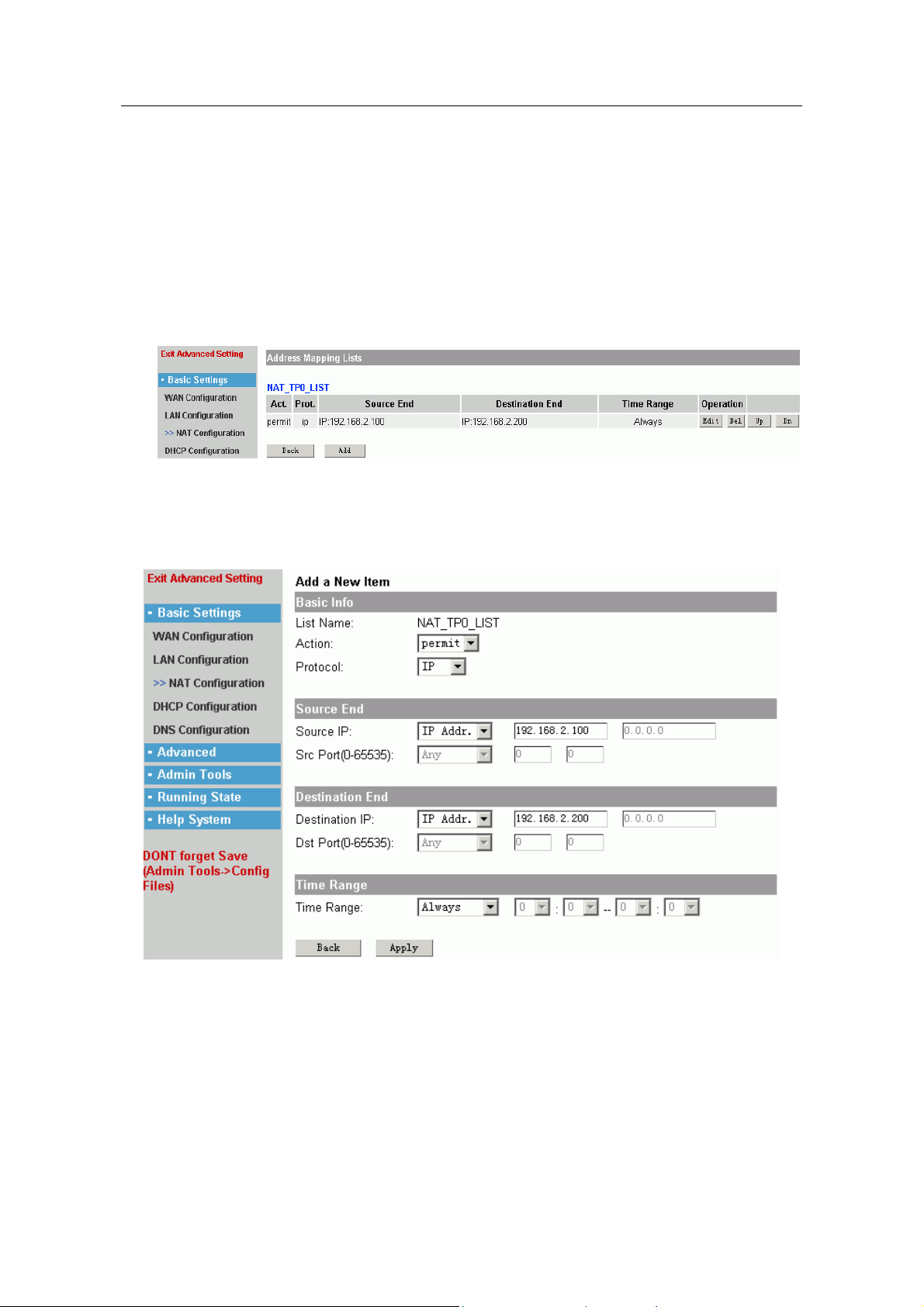
The configuration page layout is following:
There are two parts:
Connection Settings:
Max-entries: The value is used to set the max-entries for NAT mapping. ( In
order to prevent virus, usually the value is 300. It depend on using situation
- 11 -
Page 14
1705Router Web Configuration Manual
of computer. If you download something by BT, the value is more. There are
200 PC in one net-bar, about 600 is enough.)
Max-entries(per host): It is used to set max-entries for each IP.
Address Mapping Setting:
The configuration make all users in LAN share one public IP address. They can
browse Internet at one time, but the users which are in Internet can’t call users in
LAN.
There are three steps to configure router in this setting.
Ensure the port of LAN, click links of access list to enter configuration page
First:
layout:
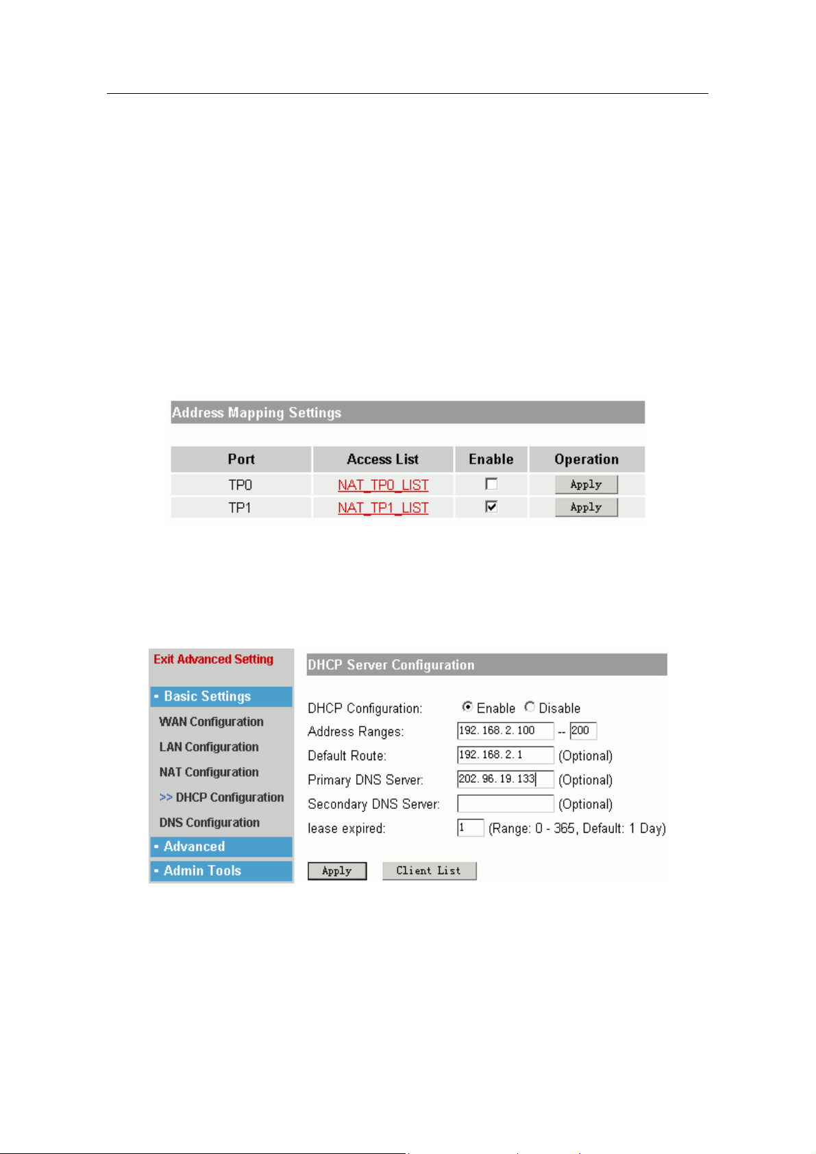
It shows the final configuration result. Click “add” to add new list, “Edit” is used to
edit the current list. “Del” is used to delete list. If there are some lists, you can
click “Up” and “Dn” to move.
Second:
add a new item to address mapping lists. Click “add” button.
The above figure shows page layout of adding item, it contains many contents,
but typical setting includes the following:
Action: permit or deny; usually you can choose permit.
Protocol: usually you can choose IP protocol.
Source IP:
any
IP Addr.
IP Range
all IP address.
――
――
――
single IP address.
range of IP address.
- 12 -
Page 15
1705Router Web Configuration Manual
IP Subnet
one IP address and one subnet mask.
――
Src port: it is only used in TCP or UDP protocol.
Any
=,>,<,!=(unequal to )
Range
——
——
all ports.
limit the value of some port.
——
range of one section port.
Typically you should select IP range in source IP to fill in PC IP of LAN, or select
IP Subnet to fill in the net-segment of LAN.
Destination IP: idem.
Destination Port: idem.
Typically the destination IP should select Any.
Time Range: Choose the efficient time range of this list. Usually we choose
always.
Click “apply” to make the configuration effective, “back” is cancel.
Third: Enable NAT function.
In the following page layout:
Select “Enable” and click “Apply” to make the list effective.
1.4.4 DHCP server configuration
This function is used to configure router as DHCP server, in order to distribute IP
address automatically for PC of LAN.
DHCP configuration: Enable or Disable.
Address range: fill in a IP address range for PC of LAN. ( The default subnet mask is
255.255.255.0).
Default Route: fill in the default router for PC in LAN, usually it is the IP address of port
that is connected LAN.
Primary or Secondary DNS server: fill in the IP address of DNS server for PC in LAN.
- 13 -
Page 16
1705Router Web Configuration Manual
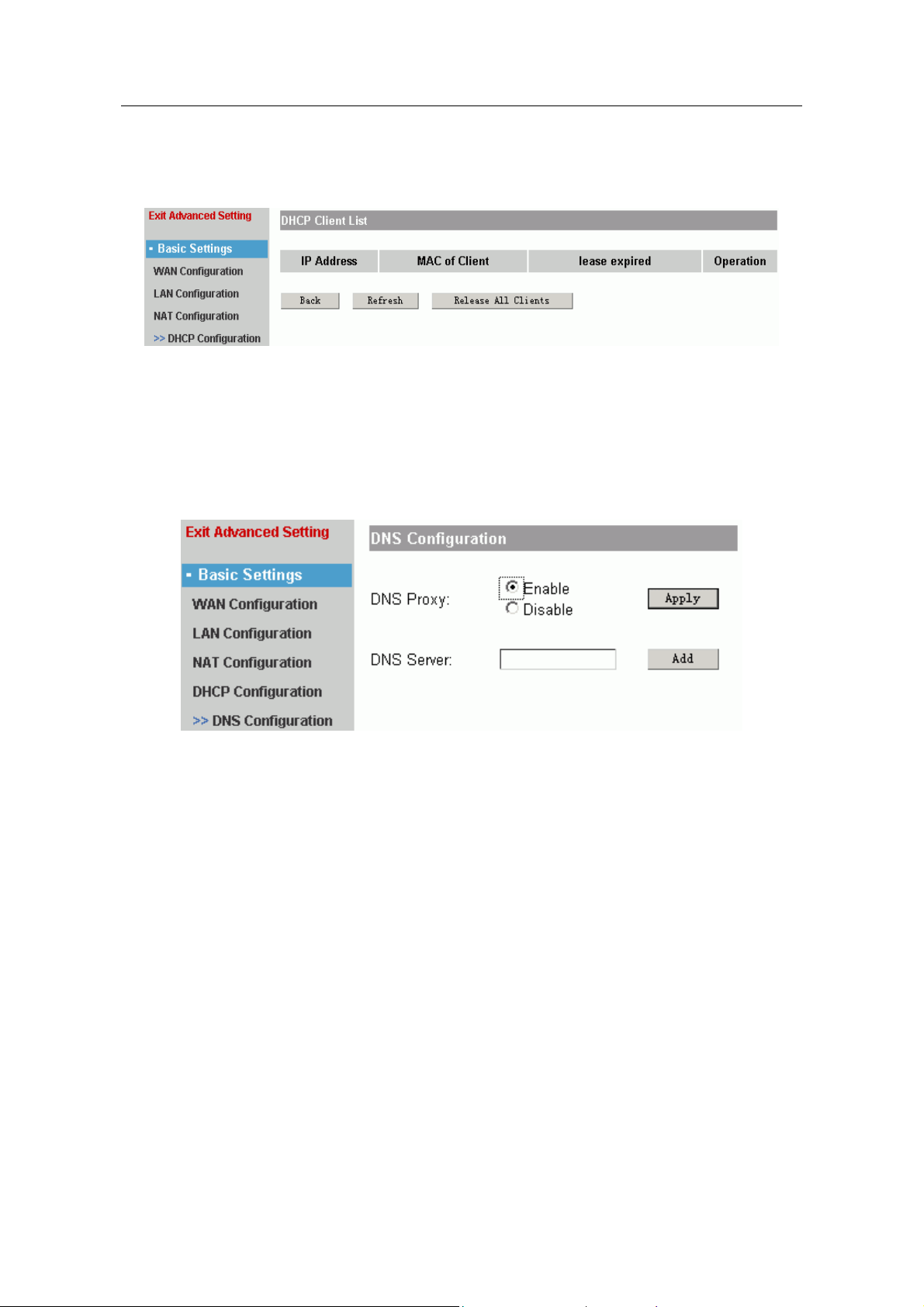
Lease expired: the useful-life of PC IP address. The default is one day.
Click “apply” to make the configuration effective. If you want to check the distributive
result, you should click “Client List”.
It shows the IP address, MAC address and lease expired of client.
Click “Refresh” to release IP address for client. Click “Release All Clients” to release all
IP address for client.
1.4.5 DNS Configuration
It is used to configure DNS.
DNS Proxy: Enable or Disable.
DNS Server: fill in a IP address of DNS, click “add” to add DNS server. You can add 6
DNS server at best.
1.5 Advanced
It includes the following submenu: “Mutiplex Line”, “Port Mapping”, “Special NAT”,
“Firewall”, “Default Route”, “Static Route”, “DDNS Settings”, “VPN Settings”. Advanced
settings can help you finish some advanced function for router.
- 14 -
Page 17
1705Router Web Configuration Manual
1.5.1 Multiplex Line
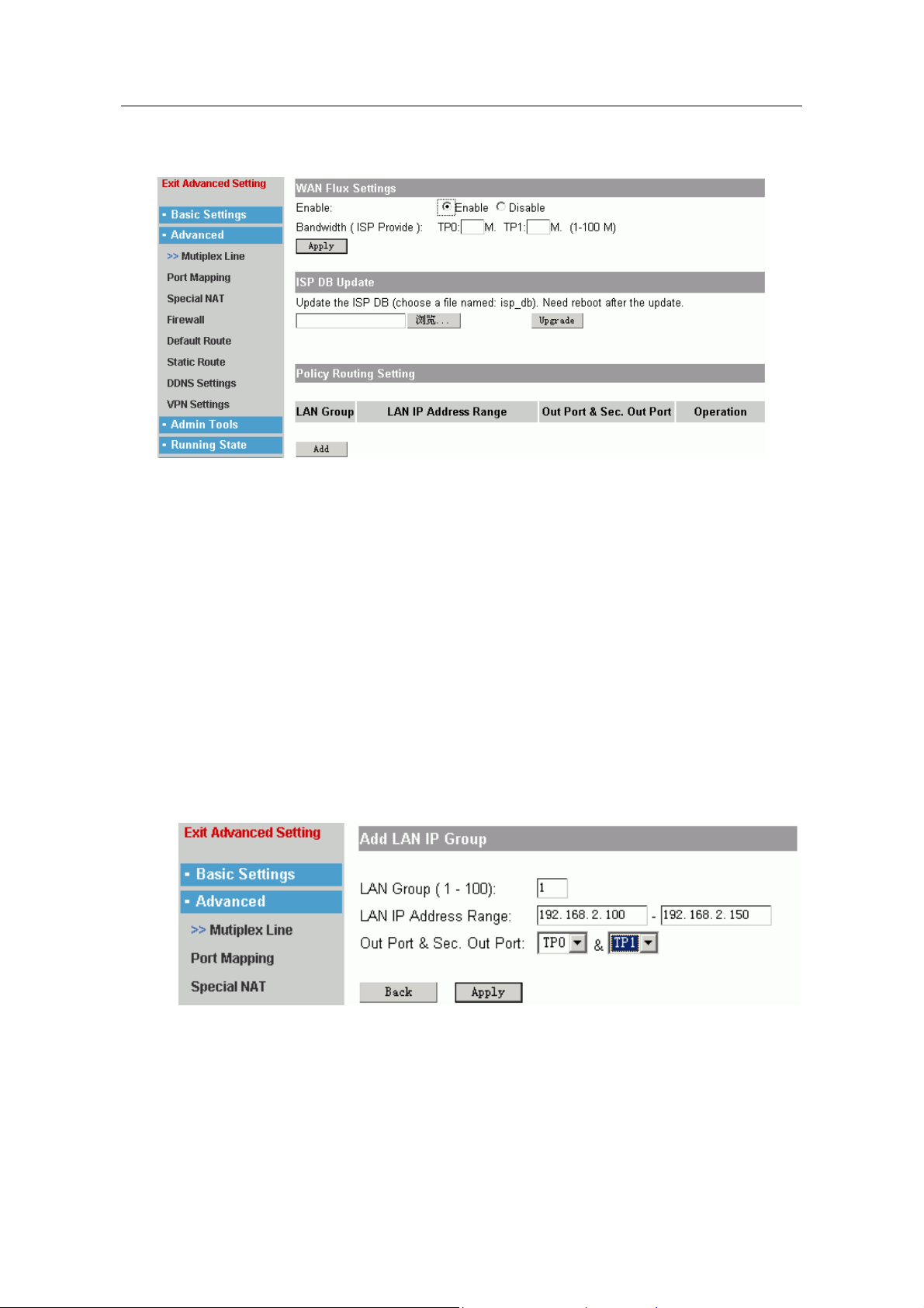
A. There are more WAN ports in router, and they can connect Internet at one time.
You could design the flux control of port according to bandwidth of every line.
You can use “ WAN Flux Setting” to achieve the control.
Enable: Enable or Disable.
Bandwidth: fill in the bandwidth provided by ISP.
Click “Apply” to make the configuration effective.
B. ISP DB Update. When system is warning that there is no file named “isp_db”, you
should click ”browse” to find this file, then click “Upgrade”, and reboot the router to
make the file effective.
C. “Policy Route Setting” is used to separate LAN into several parts, in order to make
every WAN port communicate with Internet normally.
For example: TP0 and TP1 are WAN ports, the address range of LAN is
192.168.2.100~192.168.2.200. We hope that separate LAN into two part:
192.168.2.100~192.168.2.150 browse Internet through TP0, and
192.168.2.151~192.168.2.200 browse Internet through TP1. Click “add” button:
LAN Group: fill in one number to mark different LAN net-segment.
LAN IP Address Range: fill in the address range in LAN.
Out Port & Sec. Out Port: select the WAN port to transmit the LAN's packets. (Also
can select another port as backup).
- 15 -
Page 18
1705Router Web Configuration Manual
1.5.2 Port Mapping
Port mapping is one of NAT. It is used to mapping the IP address in LAN or TCP/UDP
port of one IP address to public net, so that the users in public net could call some host
computer or serve that are in LAN.
Note:
They only call some service, but not all LAN.
For example: 192.168.2.10 and 192.168.2.11 are IP address in LAN, 202.192.2.10 and
202.192.2.11 are the rightful IP address. When 192.168.2.10 communicates with
Internet, the router will transform the source IP address of packet to 202.192.2.10, and
transmit this packet. When router receive a packet which destination IP address is
202.192.2.10, router will transform the destination IP address to 192.168.2.10 and
transmit it to host computer in LAN.
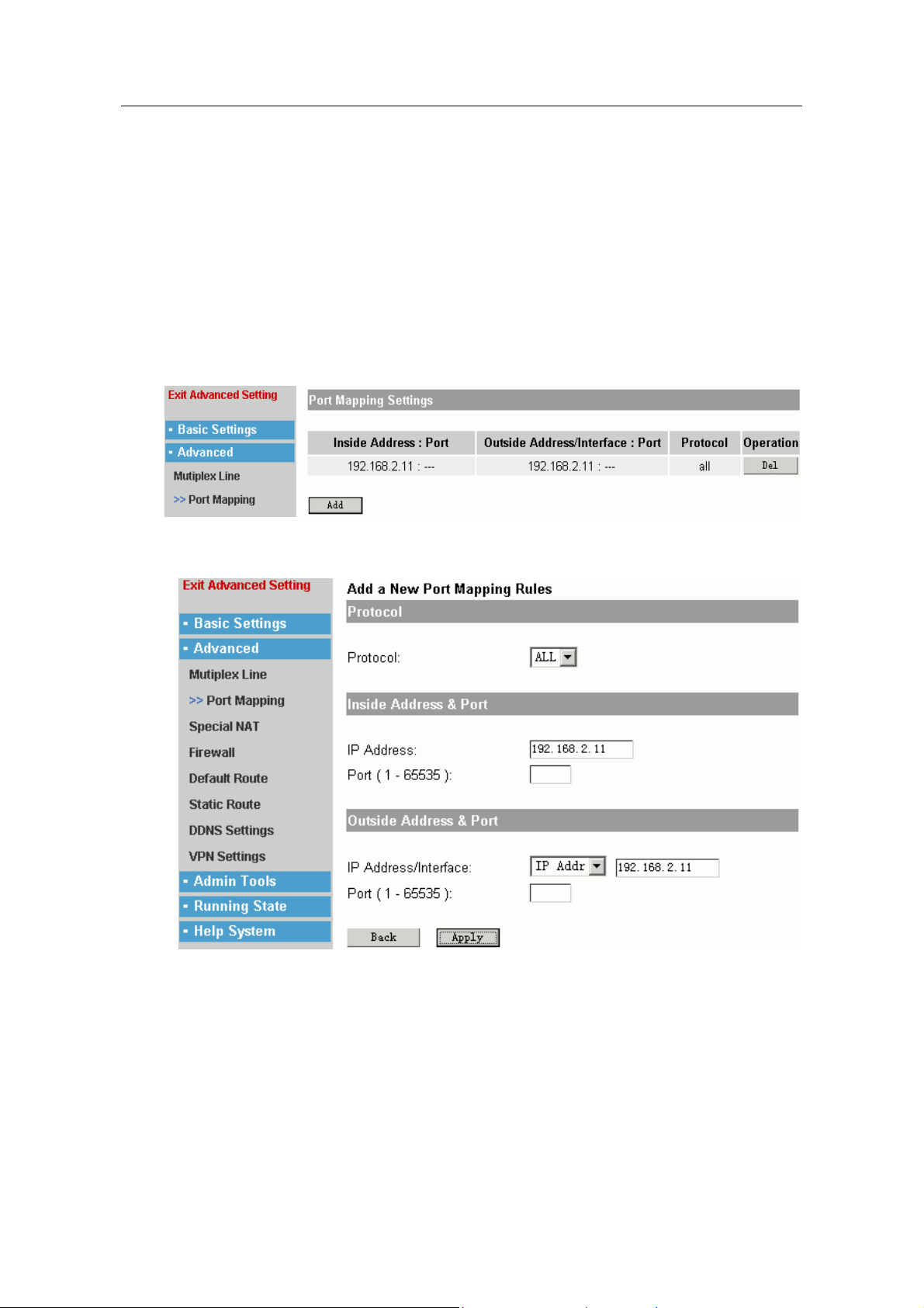
Click “add” to add the list.
Protocol: You can choose TCP, UDP or ALL. When you choose ALL, you will not design
port number.
Inside Address: It is a private address typical, that is address of host computer in LAN.
Inside port: Users could design port when inner host computer communicate with
outside.
Outside Address: It is a rightful IP address.
Outside Port: Design a external port number.
Click “Apply” to make the configuration effective, “Back” is cancel.
- 16 -
Page 19
1705Router Web Configuration Manual
1.5.3 Special Address Mapping
It is one of NAT. if you configure in NAT setting menu, it could make users in inner net
call public net; And configuration of port mapping could make users in public call some
host computer or service in inner net. But this special NAT port mapping is used to
make users in inner net call some host computer or service by public IP address of
router.
For example: 192.168.2.1 in LAN wants to call 192.168.2.2 in LAN by public IP
218.1.1.1, users should fill 218.1.1.1 in outside Address, fill 192.168.2.2 in inside
Address, and choose ALL protocol.
The configuration method of special address mapping is similar with port mapping.
Please refer to chapter 1.5.2.
1.5.4 Firewall
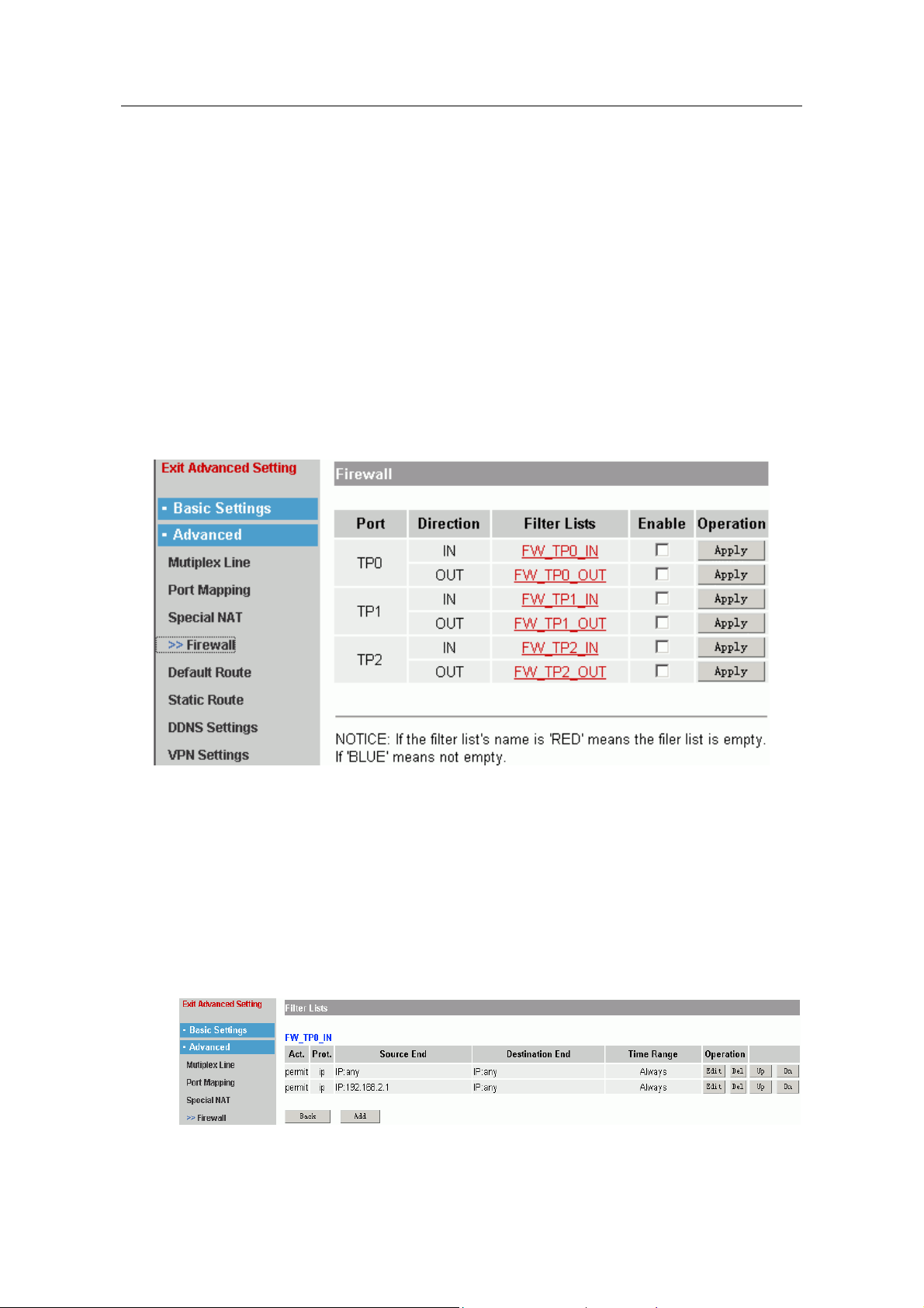
1705router is used to be a firewall by proper configuration.
The page layout shows the firewall function for every port. The firewall can screen two
directional data packet: IN(receive), OUT(send or transmit). You only need to edit the
corresponding filter list of port in order to make the firewall effective.
1. Edit the filter lists
Users could design the parameter of filter packet in filter list. If the router enable firewall
function, it will compare every entries of filter lists with source IP and destination IP of
data packet in order to judge receiving or transmitting the data packet.
Click the link of filter lists to enter configuration page layout.
- 17 -
Page 20
1705Router Web Configuration Manual
The configuration method of filter lists is similar with access list configuration of NAT.
Their difference is: access lists of NAT is used to control communication of Internet and
PC in LAN, but filter lists of firewall is used to control the filter function of data packet.
Note:
The filter lists is a order sentence concourse, it match information of packet and parameter of access lists
by superincumbent order. Its judgement rule is that stop the matching rule if it pass some rule in access
lists, and it will not compare with latter rule.
There is a question in above configuration. The user’s purpose is that abandon all
packets except source IP 192.168.2.1. The figure is configured two items to achieve the
purpose. However the router match filter lists, its first row (deny row) has already finish
the matching, and it doesn’t match the second row. In this way, even if the source IP
address of data packet is 192.168.2.1, the router will filter this data packet.
The right method is that trade order of the two list item. You can adjust by up and dn
button in right.
2. Enable Firewall
Select “Enable” and click “Apply” to make the filter function effective.
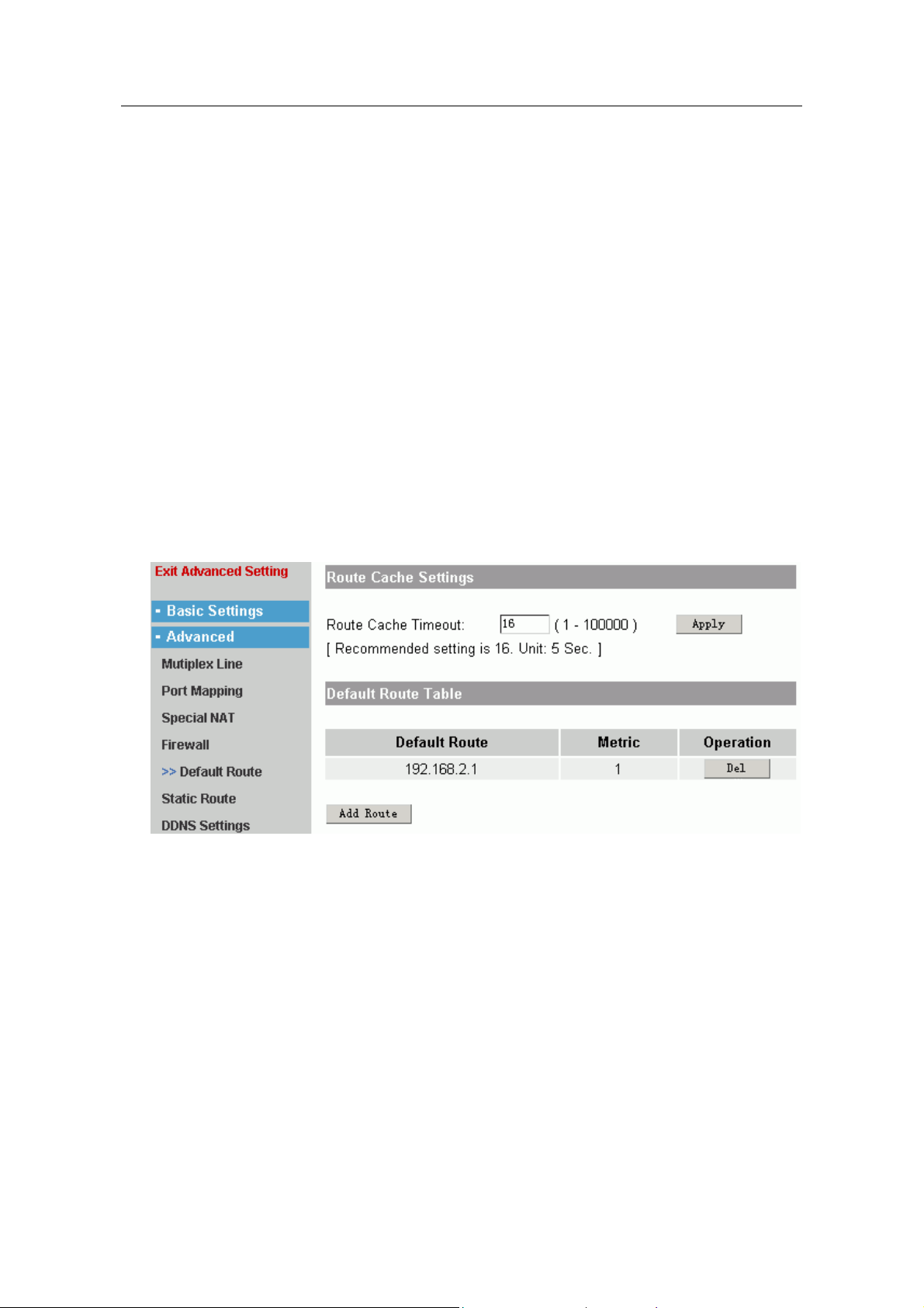
1.5.5 Default Route
There are two parts in default route page layout:
Route Cache Settings:
It is used to configure aging time of route cache. The default is 16. Usually it is
used to be default value.
Default Route Table:
Click “Add Route” to add the default route.
- 18 -
Page 21
1705Router Web Configuration Manual
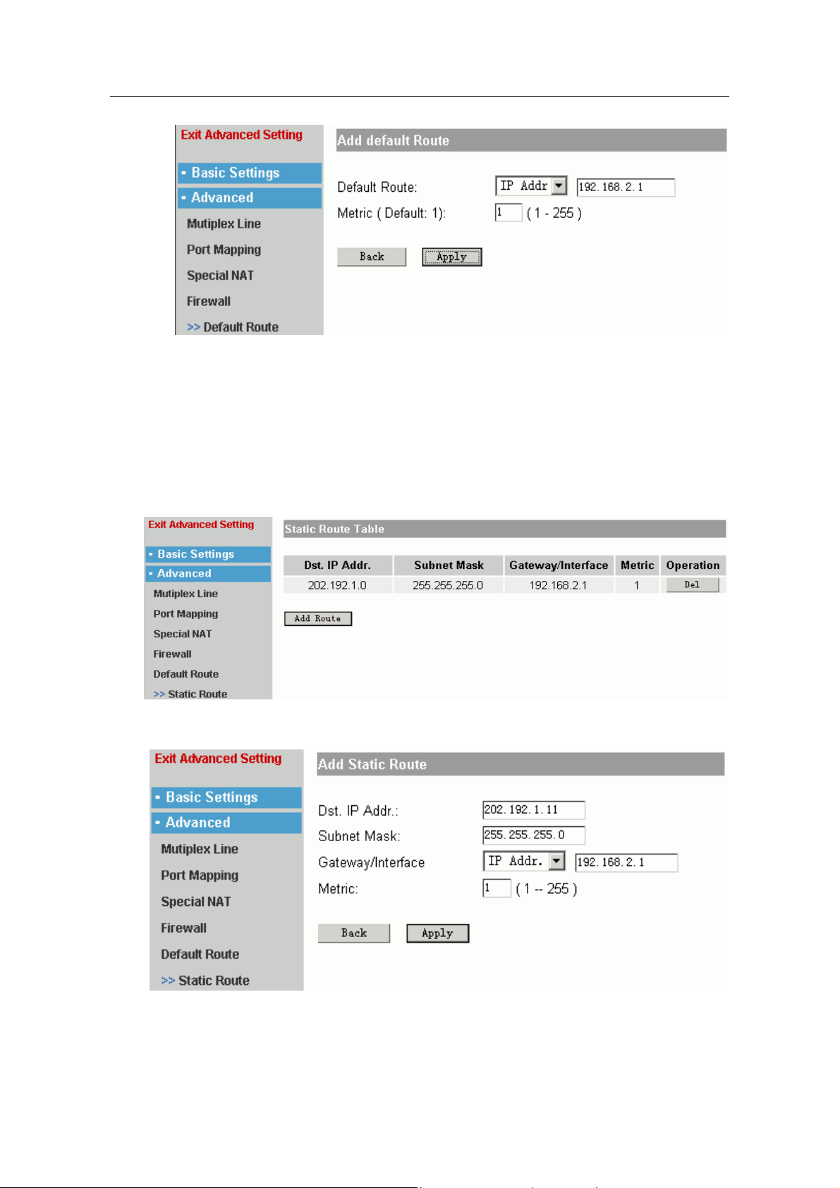
Default Route: IP Addr
Metric: select the metric of reaching default route. The default value is 1. Usually
it is used to be the default value.
1.5.6 Static Route
It is used to configure the static route.
Click “Add Route” to add a static route.
TPx
fill in the IP address of default route.
——
select a port of default route.
——
Dst. IP Addr., Subnet Mask: fill in the destination IP address and subnet mask.
Gateway/Interface: fill in the next skip address or port if reached the destination IP
address.
- 19 -
Page 22
1705Router Web Configuration Manual
Metric: the default value is 1.
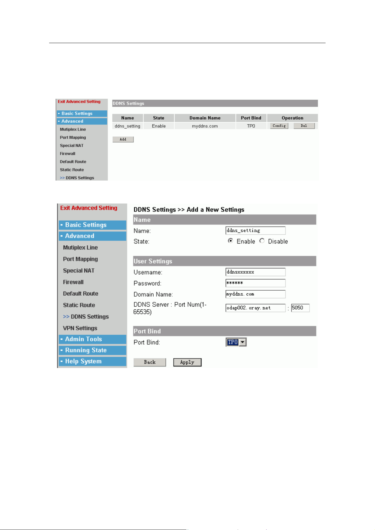
1.5.7 DDNS Settings
DDNS (dynamic DNS) only support “PeanutHull” at present.
Click “Add” to add a piece of configuration for DDNS.
Name: intitle for the setting.
State: Enable or Disable.
Username, Password: fill in the username and password that is registered in
PeanutHull net.
Domain Name: fill in the domain name which is registered in PeanutHull net.
DDNS Server, Port Num: fill in the server and port that are provided by PeanutHull. The
default that we provide one DDNS server, you could rejigger the server if you need.
Port Bind: choose one port to bind.
- 20 -
Page 23
1705Router Web Configuration Manual
1.5.8 VPN Settings
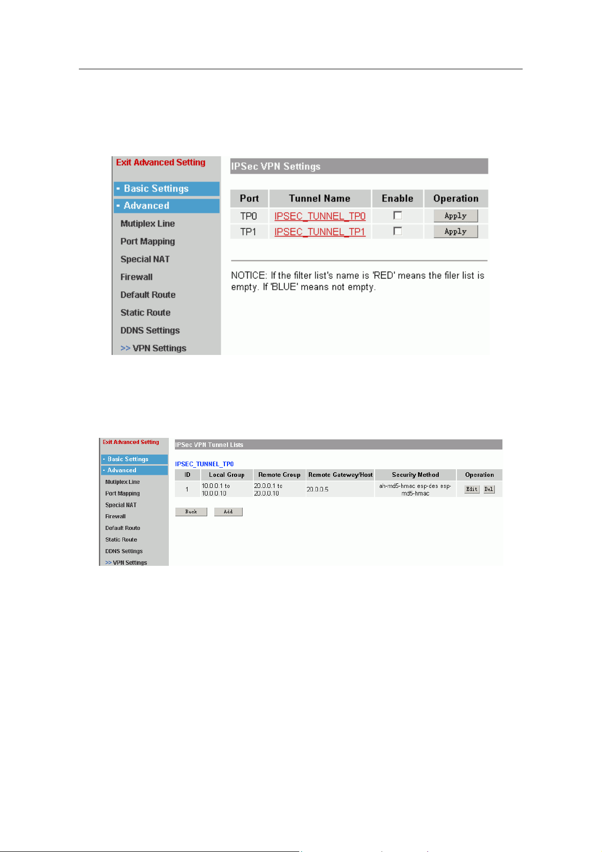
The routers support VPN, and you can configure IPSec. It is used to establish a tunnel
for either communication, and protect the communication of host computer between
tunnel.
You should ensure that configure IPSec VPN in which port. Then you could edit the list
of tunnel, establish one or more tunnels. You ‘d better enable configured tunnel lists.
Edit the tunnel lists:
Click the list of tunnel name:
It shows all configured tunnel list. You can add new tunnel or edit the configured
tunnel
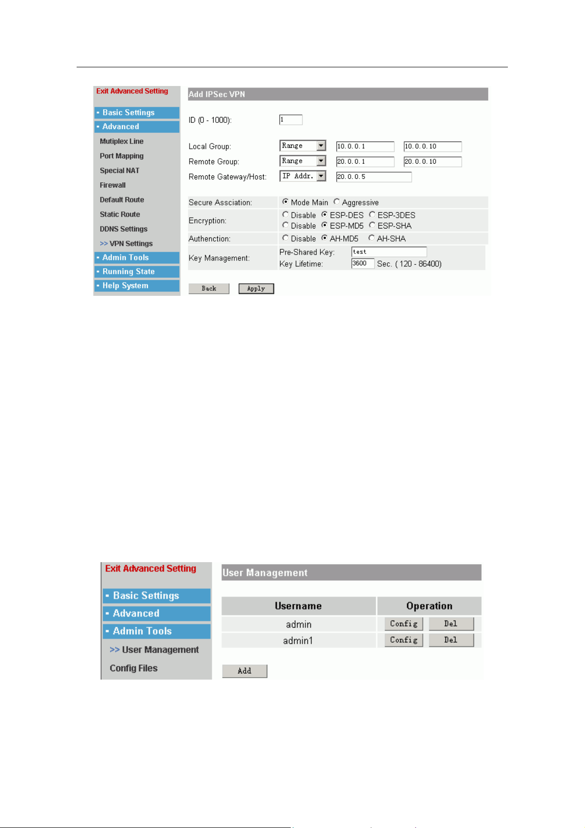
Add/Edit tunnel:
- 21 -
Page 24
1705Router Web Configuration Manual
ID: You can establish more tunnel, so you should point out ID of one tunnel.
Local Group: it shows the IP address range of local tunnel. It must suit the IP
address which is in local group so that could use IPSec.
Remote Group: It is one IP, range, mask of another end tunnel. It shows the
address of tunnel distance. IPSec only protect the communication of IP address
which is in this range.
Remote Gateway/Host: It limits the IP address range which is protected by
communication. And it appoints one specifically distanced host or address.
Secure Assciation: select Mode Main usually.
Encryption: it is the encrypt mode of tunnel communication.
Authenction: it is the authentication mode of tunnel communication.
Key Management: fill in one key which is used by tunnel.
1.6 Admin tools
This menu includes: “user Management”, “Config Files”, “IOS Software”, “Time
Settings”, “Remote Control”, “Diagnose Tool”, “Ports Define”, “System Reboot”.
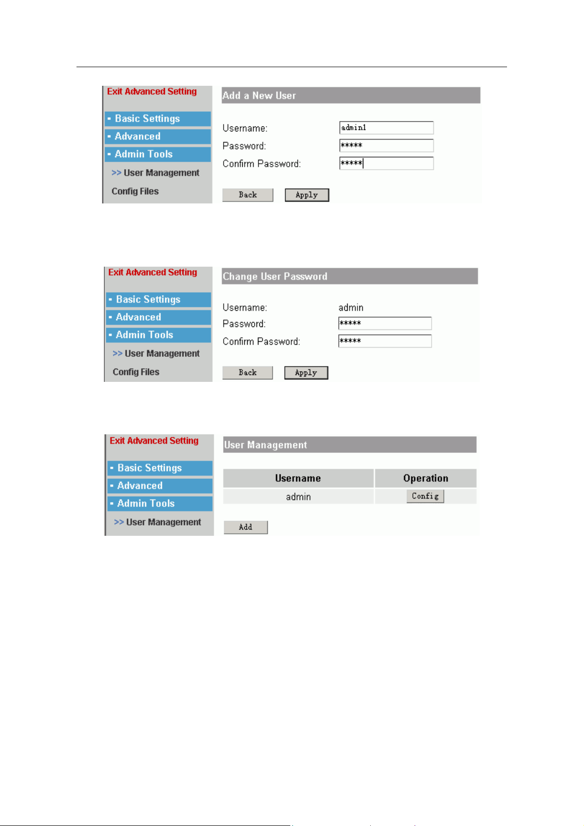
1.6.1 User Management
It shows the users who could logging on router.
Click “Add” to add new user.
- 22 -
Page 25
1705Router Web Configuration Manual
Fill in the username, password and confirm password, then click “Apply” to add new
username.
Click “Config” to alter the password.
Fill in new password and confirm, click “Apply” to alter.
Note:
system don’t provide delete function when there is only one user.
- 23 -
Page 26
1705Router Web Configuration Manual
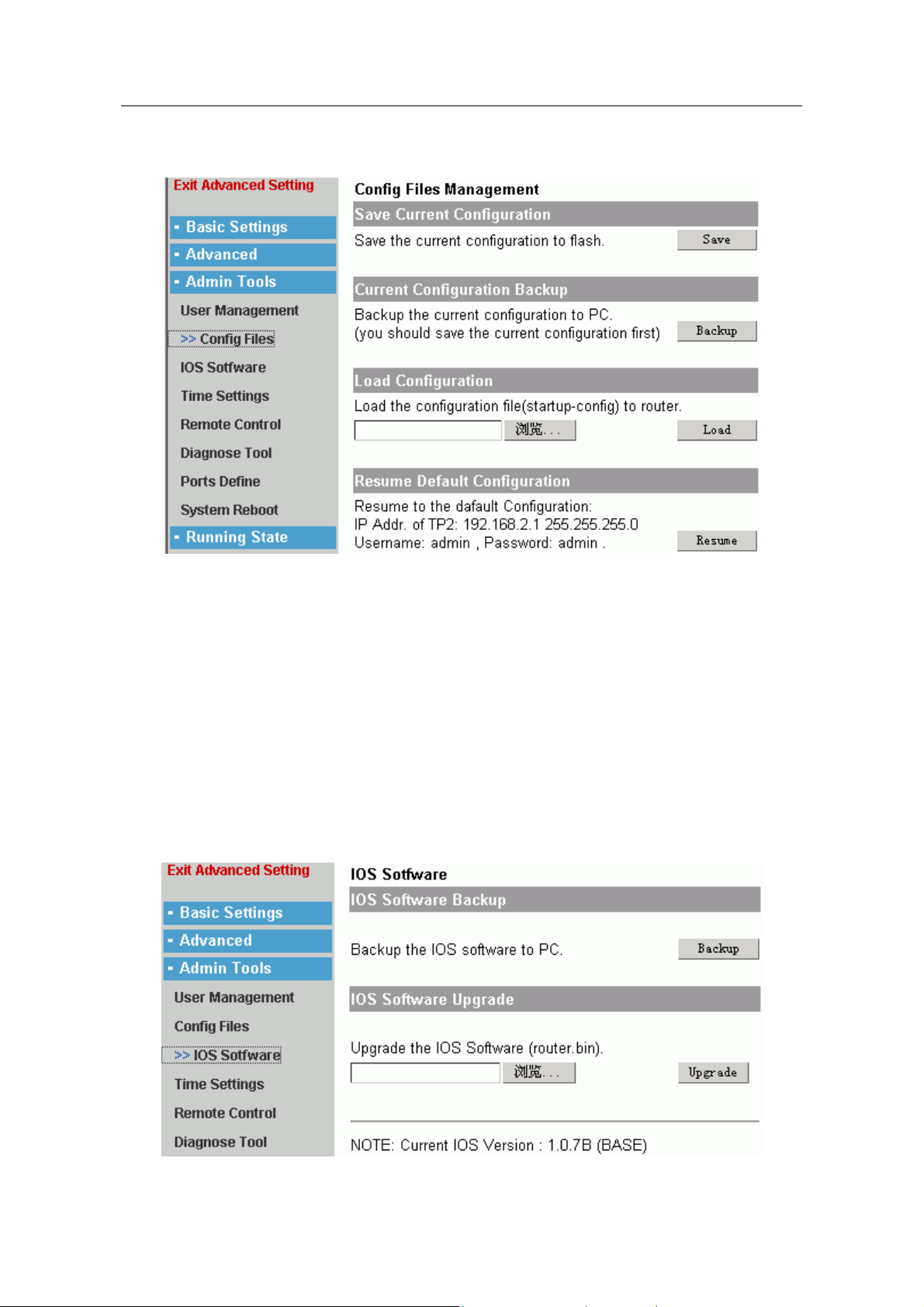
1.6.2 Config Files
Save Current Configuration: it is used to save the current configuration for router.
Current Configuration Backup: it is used to backup the configuration files. That is
downloading the startup-config file to PC in order to use at meet.
Load Configuration: it is corresponding to above item. It is used to upload the
configuration file to router, and reboot router to use the file. You must named the file
“startup-config” and ensure it is a rightful file.
Resume Default Configuration: it is used to resume the default configuration, that is the
leave-factory configuration.
Note:
These operate need any time, so that you should configure other item when system register
successfully.
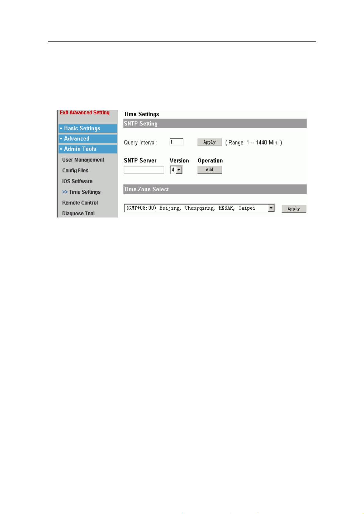
1.6.3 IOS Software
- 24 -
Page 27
1705Router Web Configuration Manual
IOS Software Backup: we issue new IOS edition in a period of time. Users could
backup old edition.
IOS software Upgrade: it is used to upgrade IOS edition. And users must named the file
“router.bin”. The IOS file must be a rightful file.
1.6.4 Time Settings
There are two parts in this page layout:
SNTP Setting:
Query Interval: it is the interval which router query SNTP Server. The default
value is 1.
SNTP Server: Users could add more SNTP server and choose 4 editions. The
default edition is 4.
Time-Zone Select: it is used to select a time-zone.
- 25 -
Page 28
1705Router Web Configuration Manual
1.6.5 Remote Control
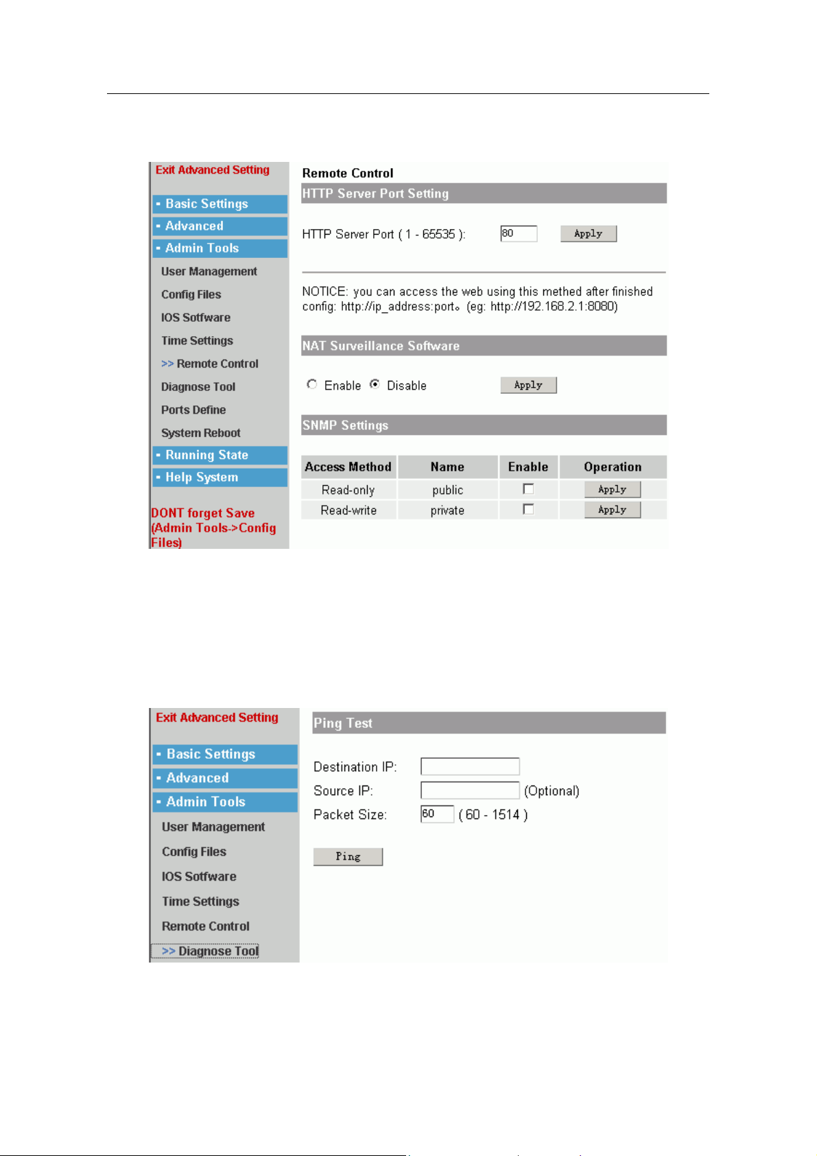
HTTP Server Port Setting: in some condition users may alter the default port to
configure Web. You should make sure this port doesn’t conflict with other port.
NAT Surveillance Software: Enable or Disable.
SNMP Settings: it is used to enable SNMP function.
1.6.6 Diagnose Tool
Ping test process is used to test that the destination IP address is reached or not, and
the loss rate of packet.
Destination IP: fill in the testing destination IP address.
- 26 -
Page 29
1705Router Web Configuration Manual
Source IP: it is used to appoint the especial port to ping the destination IP address.
Here should be filled in the IP address of especial port. It can be choose or not.
Packet Size: it is used to design the size of ping packet.
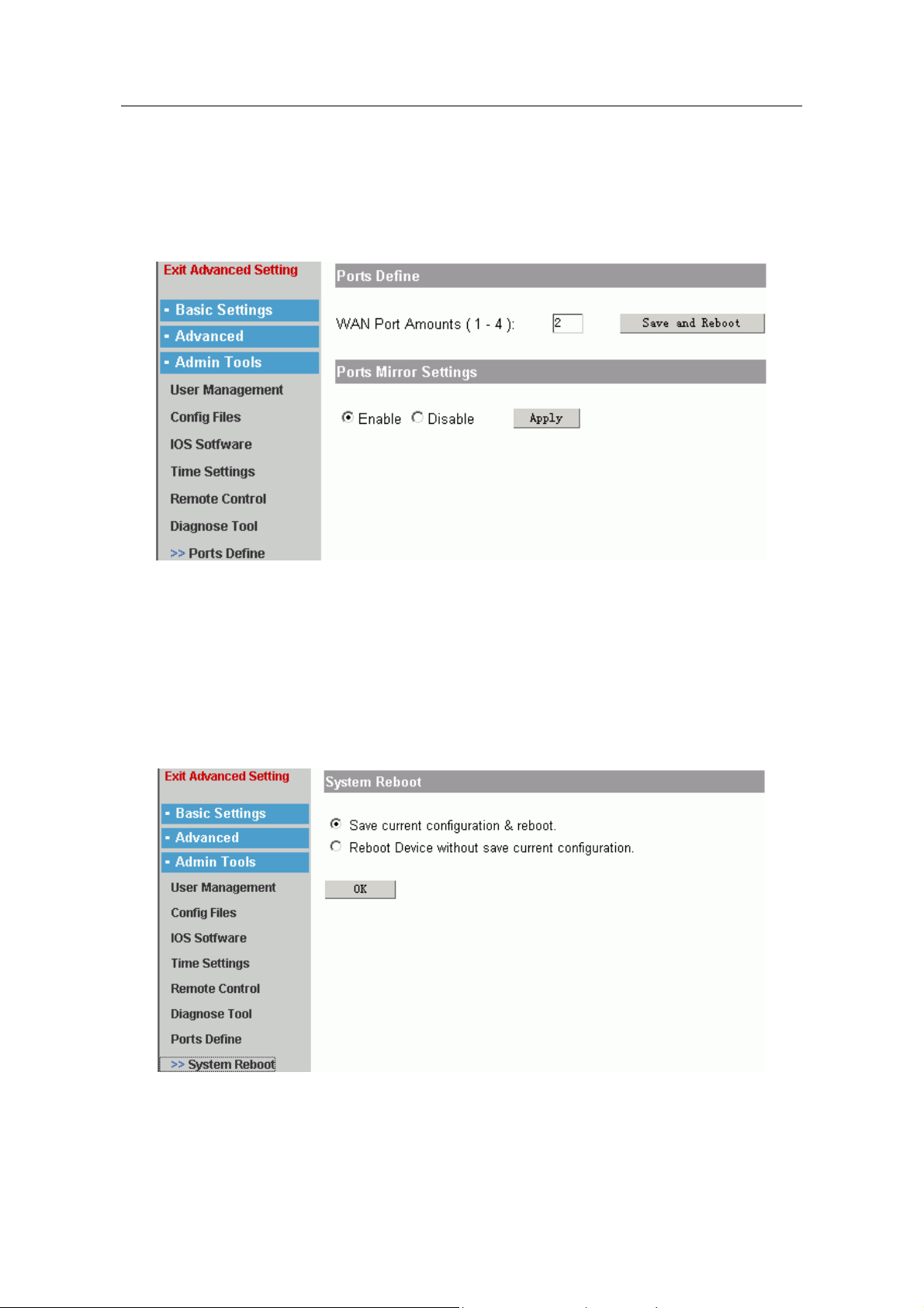
1.6.7 Port Define
The router can be set more WAN port. Users could fill in the number and click “Save
and Reboot” to make the configuration effective.
Note:
The number of WAN port is different according to different router.
Users could enable or disable Port Mirror function.
Note:
Please configure other item when system register successfully.
1.6.8 System Reboot
1.7 Running State
This menu includes: “System Info”, “System State”, “System Log”.
- 27 -
Page 30
1705Router Web Configuration Manual
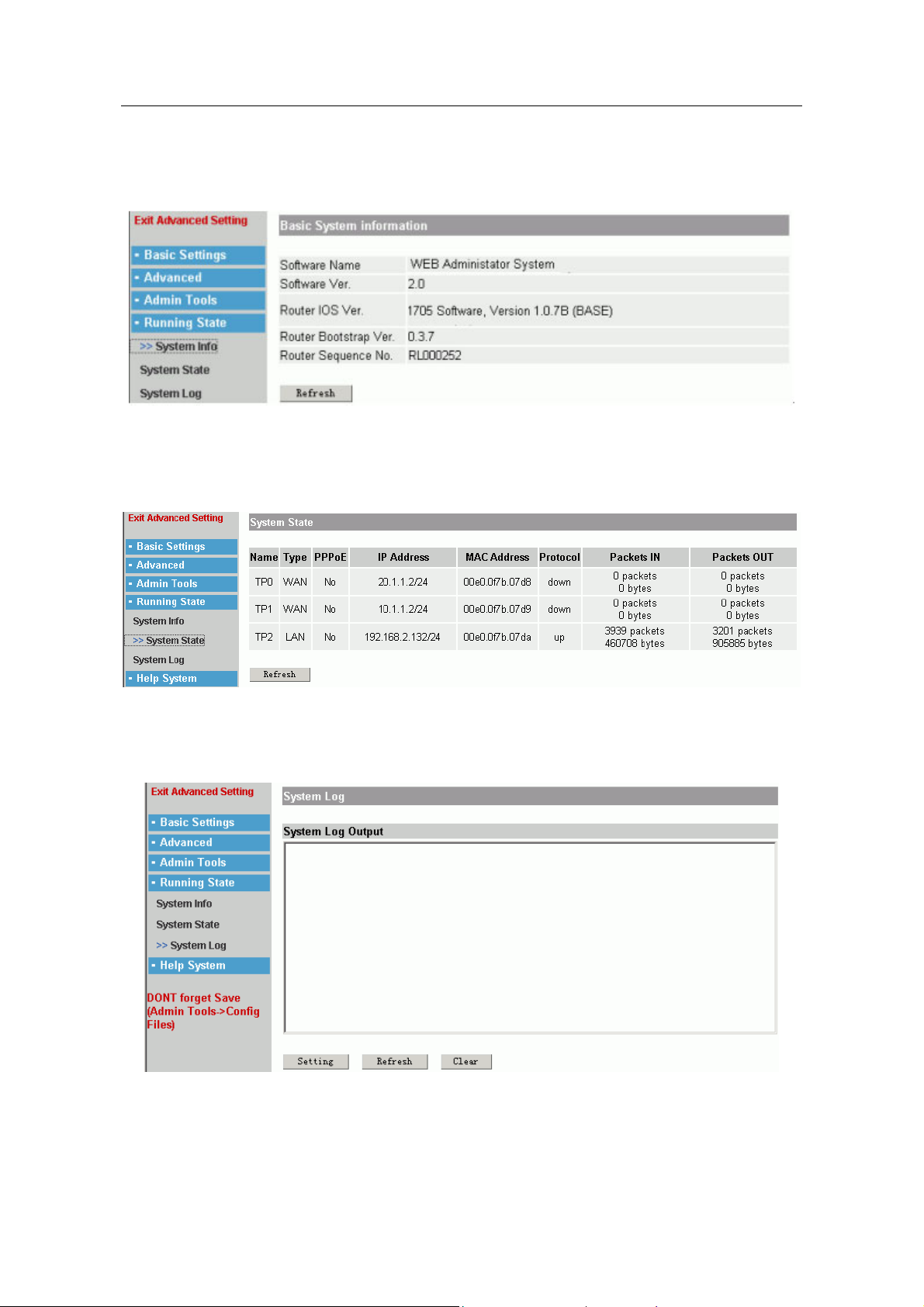
1.7.1 System Information
It is used to show the system informatiom.
1.7.2 System State
It shows the port state of system.
1.7.3 System Log
Users could know the system state by observing Log information.
The page layout shows the log information. Click “Clear” to clear the information, click
“Refresh” to show the newest log information.
Click “Setting” to set the output of log information.
- 28 -
Page 31
1705Router Web Configuration Manual
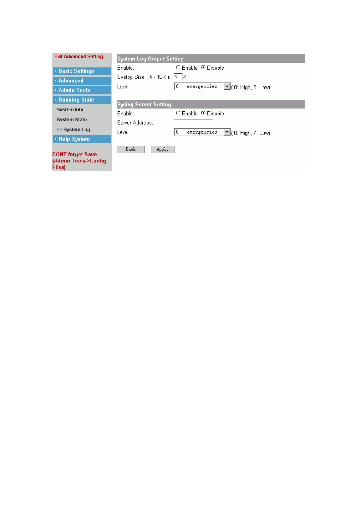
System Log Output Setting
Enable: it is used to enable or disable the output of system log. If you select
“Disable”, the log output page layout will not show any information.
Syslog Size: it is the size of log buffer.
Level: The output of Log is divided into many steps. Users could design the
output range of log.
Syslog Server Setting:
Enable: enable this function, the log will output in appointed log server.
Server Address: the address of log server.
Level: Above.
- 29 -
 Loading...