

Page 1

6 November 2006 1085200/5210/5220 Dodge X-Monitor 1
BD X-MONITOR
1994-2007 Dodge Ram 5.9L Cummins
Installation Manual
Date Purchased
Purchased from
Installed by
READ THIS MANUAL COMPLETELY BEFORE INSTALLING THIS PRODUCT.
OWNER’S MANUAL - LEAVE IN GLOVE BOX
Installation Manual Part # I1085200
Printed in Canada
BD Engine Brake Inc
A10 – 33733 King Rd, Abbotsford, BC, Canada V2S 7M9
Ship: 88 – 446 Harrison St, Sumas, WA 98295 Mail: PO Box 231, Sumas, WA 98295
Ph: 604.853.6096 Fax: 604.853.8749 Internet: www.bd-power.com
Page 2

6 November 2006 1085200/5210/5220 Dodge X-Monitor 2
TABLE OF CONTENTS
Kit Contents..............................................................................................................3
Welcome....................................................................................................................4
Pre-Installation .........................................................................................................4
Installation ................................................................................................................5
Pyrometer Sending Unit Assembly ...................................................................5
Thermocouple Wiring...............................................................................6
Boost Pressure Sender Assembly ....................................................................7
Basic Installation with Transmission Temperature............................................8
Automatic Transmission Temperature Sensor.........................................9
NOTE for 1999 model year....................................................................10
Remote Oil Temperature (Diff / Manual Trans / Etc).......................................11
Remote Temp Wiring Diagram ..............................................................11
Brake Back Pressure ......................................................................................12
Back Pressure Wiring Diagram..............................................................13
Lift Pump Fuel Pressure (1998½-2002)..........................................................14
Lift Pump Fuel Pressure (2003-2007).............................................................15
Wiring Diagram – Lift Pump Pressure....................................................16
Auxiliary Fuel Tank Level................................................................................17
Fuel Pressure Sensor Power and Ground......................................................18
X-Monitor Power and Ground .........................................................................18
Display Assembly Installation..........................................................................19
A-Pillar Mounts ......................................................................................19
Programming and Set Up...................................................................................... 20
X-Monitor Programming Chart..............................................................................21
Operation ................................................................................................................22
Recommended Alarm Settings .......................................................................22
X-Monitor Display Settings....................................................................................23
Maintenance & Troubleshooting...........................................................................24
LIMITED WARRANTY STATEMENT......................................................................25
BD Engine Brake Inc
A10 – 33733 King Rd, Abbotsford, BC, Canada V2S 7M9
Ship: 88 – 446 Harrison St, Sumas, WA 98295 Mail: PO Box 231, Sumas, WA 98295
Ph: 604.853.6096 Fax: 604.853.8749 Internet: www.bd-power.com
Page 3

6 November 2006 1085200/5210/5220 Dodge X-Monitor 3
Kit Contents
1830030
Universal Installation Kit
Includes thermocouple, bushing, a vacuum boost tube connection (for
the control module), 6ft of 1/8” air tubing, and a fused power wire with
ground wire.
1300837 1/8” Boost Fitting 1820210 Control Module
Display Kit (Side Button) 1830010 Sensor Wire Kit
BD Engine Brake Inc
A10 – 33733 King Rd, Abbotsford, BC, Canada V2S 7M9
Ship: 88 – 446 Harrison St, Sumas, WA 98295 Mail: PO Box 231, Sumas, WA 98295
Ph: 604.853.6096 Fax: 604.853.8749 Internet: www.bd-power.com
Page 4

6 November 2006 1085200/5210/5220 Dodge X-Monitor 4
Welcome
Thank you for purchasing the BD X-Monitor. Your kit should have the abovementioned items for your installation. This manual is divided into different areas to
assist you with your installation and operation of your unit.
Pre-Installation
If you have existing gauges installed, you may have to determine where to
reposition them to accommodate the X-Monitor. The X-Monitor mounts on the
driver’s side A-pillar panel, or, a custom dash-top universal kit can be purchased as
well.
This X-Monitor comes with all the programming to measure exhaust temperature
and boost pressure, plus the option of adding one of the following: automatic
transmission temperature (using the OEM sensor), remote tem
perature sender (for
use with differentials for example), exhaust brake backpressure, fuel pressure and
aftermarket fuel tank levels.
Here are the standard list measurements:
Exhaust Gas Temperature
(PYRO)
Turbo Boost Pressure (TURBO)
The above two measurements can be displayed by themselves or you can add one
of these options along with them:
Description Value BD P/N#
Transmission Temperature (TRANS) INCLUDED
Remote Oil Temp (OIL) 1080125
Exhaust Brake Back Pressure (B-PSI) 1080135
Fuel Pressure (F-PSI) 1080156
Auxiliary Tank Level (FUEL) 1080160 *
* The fuel tank level accessory kit interfaces with an aftermarket level sender with a
range of 240ohms (Empty) to 33ohm
s (Full). Sender is not included.
The standard kit comes with all the components and wiring to hook up the exhaust
temperature, turbo boost pressure and automatic transmission temperature (using
the trucks OEM sensor) - all other applications will require one of the accessories
above to i
nstall.
Once the components have been installed, the X-Monitor will have to be
programmed to match the application and the measurements being monitored. This
will be done via the buttons on the display and will be explained further in this
manual. If you wish to change from one optional measurement to another, the X-
BD Engine Brake Inc
A10 – 33733 King Rd, Abbotsford, BC, Canada V2S 7M9
Ship: 88 – 446 Harrison St, Sumas, WA 98295 Mail: PO Box 231, Sumas, WA 98295
Ph: 604.853.6096 Fax: 604.853.8749 Internet: www.bd-power.com
Page 5
6 November 2006 1085200/5210/5220 Dodge X-Monitor 5
Monitor can be reprogrammed to that application but an additional accessory kit
may be required.
The following sections will give detail on the install of each measurement available
but not all will apply to your installation.
Installation
NOTE: The ground terminals of the vehicle’s batteries should be disconnected
before performing any welding or taping onto any ECM/PCM wire.
Pyrometer Sending Unit Assembly
If your existing exhaust does not have a fitting to install a pyrometer sender unit
(thermocouple), you will have to install the bushing supplied in this kit. The best
place to locate the thermocouple is in the turbocharger down pipe.
If you have a TURBO-MOUNT EXHAUST BRAKE or an after market down pipe
installed, there may be a 1/4” NPT plug already in the system. Remove this plug
and install the supplied thermocouple into the 1/4” NPT hole and tighten with an
open-ended wrench. We recommend using an anti-seize compound on the threads
of the thermocouple.
BD Engine Brake Inc
A10 – 33733 King Rd, Abbotsford, BC, Canada V2S 7M9
Ship: 88 – 446 Harrison St, Sumas, WA 98295 Mail: PO Box 231, Sumas, WA 98295
If you have an OEM or stock down pipe, then you will have to drill a hole and then
weld the bushing that is supplied with this kit in place. It is recommended that you
remove the existing down pipe for ease of drilling and welding but it is possible to
Ph: 604.853.6096 Fax: 604.853.8749 Internet: www.bd-power.com
Page 6

6 November 2006 1085200/5210/5220 Dodge X-Monitor 6
install with this pipe in place. Install the thermocouple into the ¼” pipe plug and
tighten it with an open-ended wrench. We recommend using an anti-seize
compound on the threads of the thermocouple.
Pre-Turbo
: The thermocouple can be installed before the turbo by drilling and
tapping a 1/4” NPT port in the exhaust manifold. Special attention is required with
these installations to make sure drilling and tapping are not being done on points
that could cause cracking of the manifold or that debris does not enter the turbo or
engine. It is recommended that the manifold be removed to perform this work. Age
and condition of the manifold should be taken into consideration before performing
this type of installation.
Thermocouple Wiring
Route the thermocouple wire towards the firewall, taking precaution to keep it away
from hot and moving parts, and then pass it through the firewall by piercing a large
rubber grommet in the firewall beside the brake booster canister.
NOTE: Do NOT cut or splice the thermocouple lead wire, as it is special wire
that provides correct reading to the gauge. Simply
coil any excess wire out of
the way. If the thermocouple wire is too short, call factory for longer leads.
From under the dash, route the thermocouple to the X-Monitor Control Modul
e.
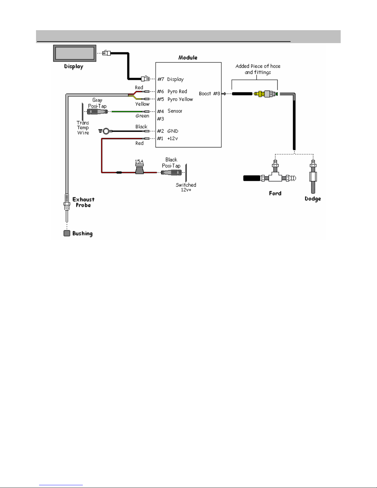
Install the wires onto the Control Module as shown in the diagram.
CAUTION: DO NOT MIX UP THESE WIRES, ENSURE YELLOW TO YELLOW
AND RED TO RED OR DAMAGE WI
LL RESULT AND WARRANTY WI
LL BE
VOIDED.
BD Engine Brake Inc
A10 – 33733 King Rd, Abbotsford, BC, Canada V2S 7M9
Ship: 88 – 446 Harrison St, Sumas, WA 98295 Mail: PO Box 231, Sumas, WA 98295
Ph: 604.853.6096 Fax: 604.853.8749 Internet: www.bd-power.com
Page 7
6 November 2006 1085200/5210/5220 Dodge X-Monitor 7
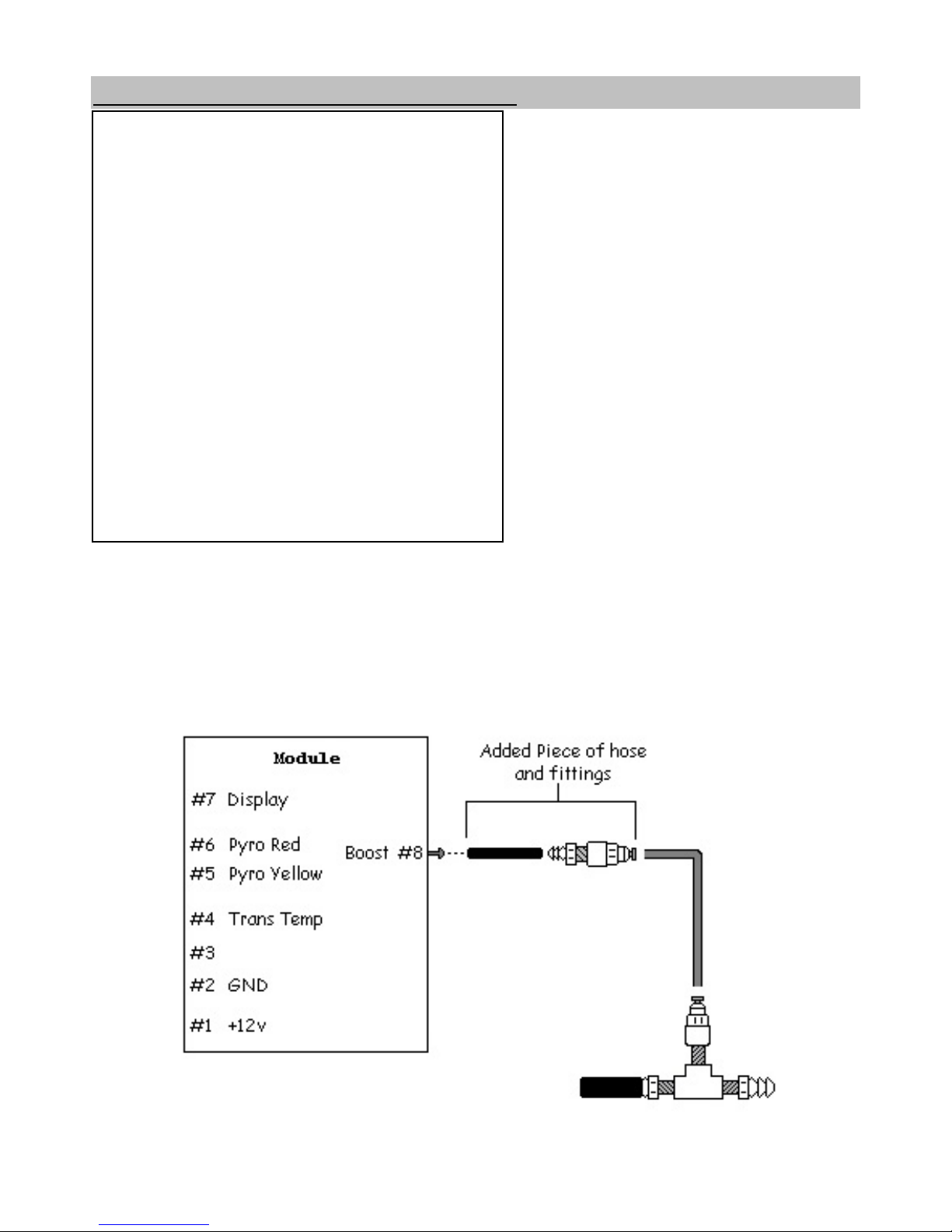
Boost Pressure Sender Assembly
Locate and remove one of the intake
plenum-to-manifold bolts and install
the drilled bolt provided with this kit
and tighten to the proper
specifications. (These bolt holes all
open into the intake manifold)
BD Engine Brake Inc
A10 – 33733 King Rd, Abbotsford, BC, Canada V2S 7M9
Ship: 88 – 446 Harrison St, Sumas, WA 98295 Mail: PO Box 231, Sumas, WA 98295
Attach one end of the supplied 6’
piece of 1/8” plastic air hose onto the
open fitti
ng and route it through the
firewall by piercing a large rubber
grommet beside the brake booster
canister.
Route the hose into the cab under
the dash taki
ng care not to kink the
tubing and to keep it away from hot
and movi
ng parts.
Push this end into the supplied fitti
ng (see diagram below) and connect the rubber
hose to the pressure sensor on the back of control box. MAKE SURE TO USE THE
RUBBER HOSE AND NOT THE PLASTI
C TUBING WHEN MAKING THIS
CONNECTION.
NOTE: The module should be mounted with the boost fitting pointed down.
Ph: 604.853.6096 Fax: 604.853.8749 Internet: www.bd-power.com
Page 8
6 November 2006 1085200/5210/5220 Dodge X-Monitor 8
Basic Installation with Transmission Temperature
BD Engine Brake Inc
A10 – 33733 King Rd, Abbotsford, BC, Canada V2S 7M9
Ship: 88 – 446 Harrison St, Sumas, WA 98295 Mail: PO Box 231, Sumas, WA 98295
Ph: 604.853.6096 Fax: 604.853.8749 Internet: www.bd-power.com
Page 9
6 November 2006 1085200/5210/5220 Dodge X-Monitor 9
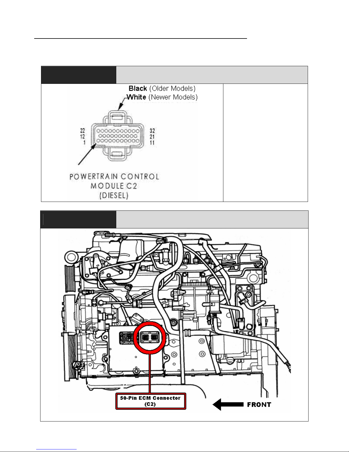
Automatic Transmission Temperature Sensor
Locate the transmission temperature monitor wire at the PCM connector on 19982003 and the ECM on 2004-07 model years.
1996-2003
PCM C2 (Center Block) Pin 1 –
Violet Wire
Pin 1 – Transmission
Temperature Sensor
Signal (Violet)
BD Engine Brake Inc
A10 – 33733 King Rd, Abbotsford, BC, Canada V2S 7M9
Ship: 88 – 446 Harrison St, Sumas, WA 98295 Mail: PO Box 231, Sumas, WA 98295
2004-2007
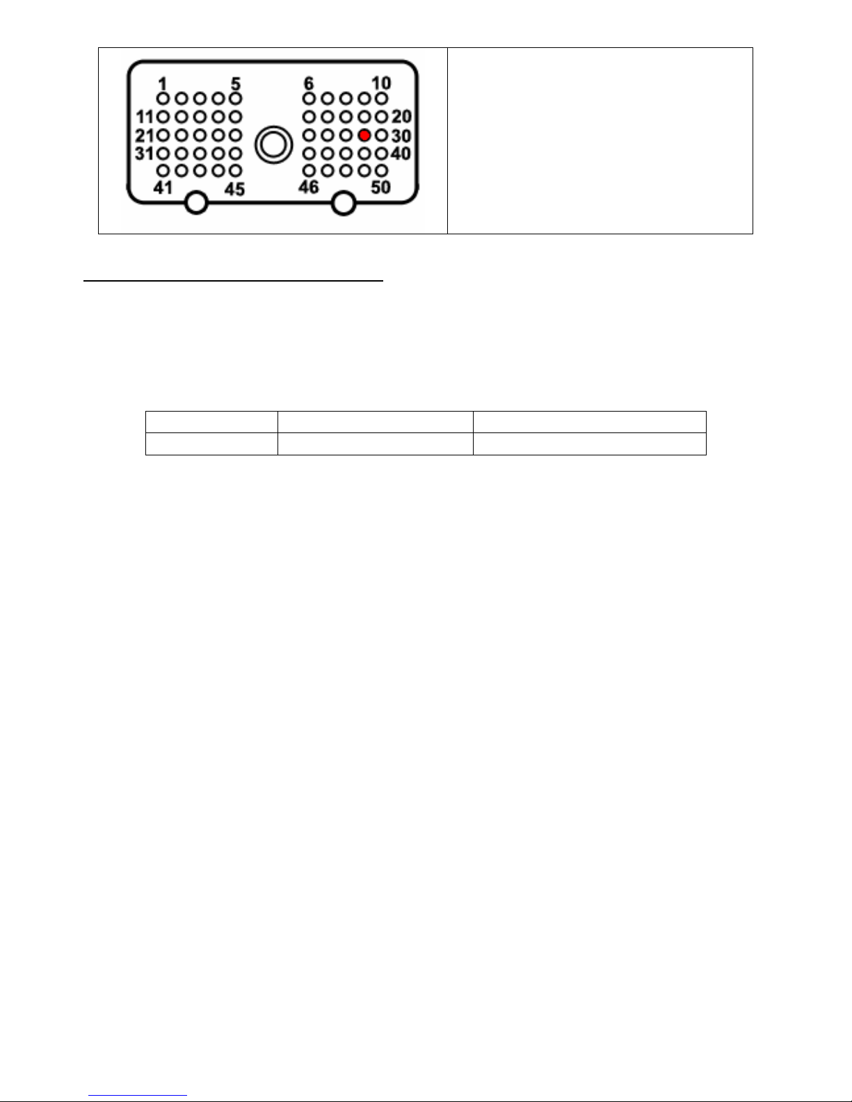
ECM C2 (50-pin block closest to the firewall) Pin 29 -
Dark green w/ orange tracer wire
Ph: 604.853.6096 Fax: 604.853.8749 Internet: www.bd-power.com
Page 10
6 November 2006 1085200/5210/5220 Dodge X-Monitor 10
ECM C2
(50-pin block closest to the firewall)
Pin 29 -
Dark green w/ orange tracer wire
NOTE for 1999 model year
In some of the 1999 model year vehicles, Dodge had a different PCM that would
give a lower reference voltage output than what the conventional PCM used for the
transmission temperature sender throughout the 1998-2003 model years. To
ensure that the proper program is being used, measure the voltage on the violet
wire on Pin 1 of plug C2 on the PCM at an ambient temperature of 40-100°F:
2 - 2.75 Volts Conventional Sender Use Program # 1085010 *
1 - 1.75 Volts Low Voltage Sender Use Program # 1085012 *
* Programming is explained in the “Programming and Set-up” section later in this install manual.
BD Engine Brake Inc
A10 – 33733 King Rd, Abbotsford, BC, Canada V2S 7M9
Ship: 88 – 446 Harrison St, Sumas, WA 98295 Mail: PO Box 231, Sumas, WA 98295
Ph: 604.853.6096 Fax: 604.853.8749 Internet: www.bd-power.com
Page 11
6 November 2006 1085200/5210/5220 Dodge X-Monitor 11
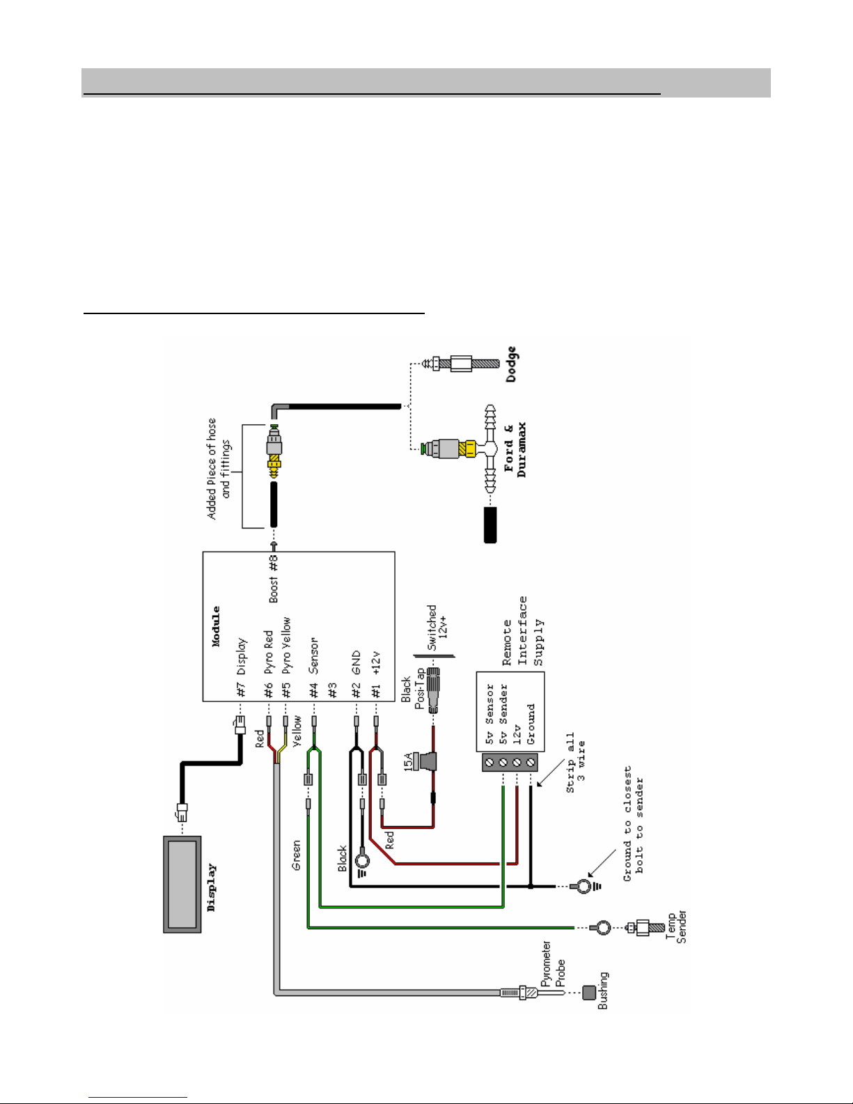
Remote Oil Temperature (Diff / Manual Trans / Etc)
Using the parts supplied with the remote temperature accessory kit, insert the
temperature sender into the large bushing. This will replace the rear differential
housing fill plug on the back cover. To use this feature to monitor the temperature of
your manual transmission, locate the appropriate location for the sender to fit.
NOTE: Not all locations will accommodate the size of the sender or the bushings
suppli
ed in the kit. An alternativ
e location, sender, or bushing may have to be
purchased to be installed in the desired location.
Remote Temp Wiring Diagram
BD Engine Brake Inc
A10 – 33733 King Rd, Abbotsford, BC, Canada V2S 7M9
Ship: 88 – 446 Harrison St, Sumas, WA 98295 Mail: PO Box 231, Sumas, WA 98295
Ph: 604.853.6096 Fax: 604.853.8749 Internet: www.bd-power.com
Page 12

6 November 2006 1085200/5210/5220 Dodge X-Monitor 12
Brake Back Pressure
On the BD Exhaust Brake valve there is a 1/8” NPT plug used for measuring brake
back pressure. Remove this plug and install the tube fitting with 1/8” NPT male
threads. One end of the formed piece of stainless tube has a fitting attached and
other end is bare - Insert the bare end into the fitting on the brake valve.
Secure the stainless tube to one of the manifol
d studs using the supplied hardware
in the brake pressure kit. Connect the pl
astic tubing to the fitting on the end of the
stainless tube, run it into the cab and connect it to the filter attached to the RPS
module.
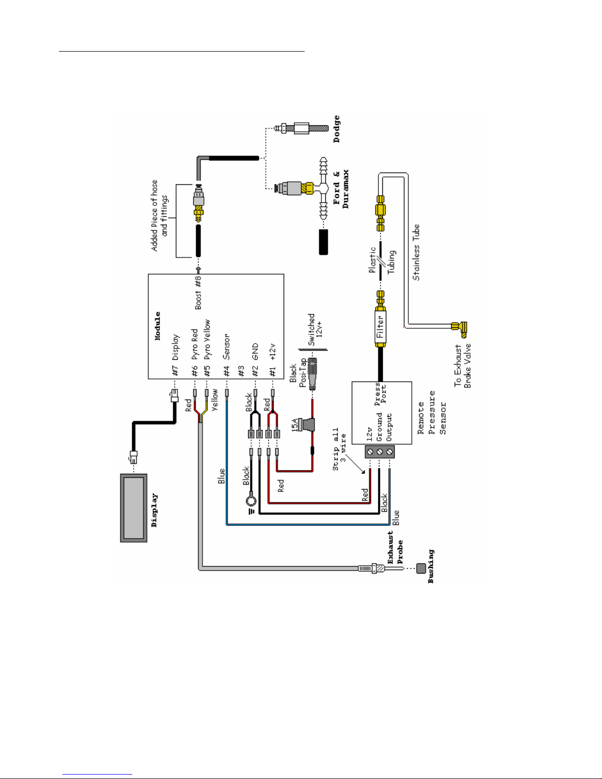
Connect the RPS module to the X-Monitor module as per diagrams and secure all
wires and tubing, keeping them away from heated or moving components.
The plastic filter housing will need to be changed out after 6-12 months of use.
The replacement time is dependant on air humidity and the amount of moisture that
is trapped in the actual fil
ter. The replacement filter part # is 1800135
. This filter
should be mounted in a visible, easy to access location.
Because of the moisture accumulating in the line and filter, it is highly recommended
that the RPS unit be mounted at the highest point of the air line causing all the
moisture to run back down the line into the exhaust.
BD Engine Brake Inc
A10 – 33733 King Rd, Abbotsford, BC, Canada V2S 7M9
Ship: 88 – 446 Harrison St, Sumas, WA 98295 Mail: PO Box 231, Sumas, WA 98295
Ph: 604.853.6096 Fax: 604.853.8749 Internet: www.bd-power.com
Page 13
6 November 2006 1085200/5210/5220 Dodge X-Monitor 13
BD Engine Brake Inc
A10 – 33733 King Rd, Abbotsford, BC, Canada V2S 7M9
Ship: 88 – 446 Harrison St, Sumas, WA 98295 Mail: PO Box 231, Sumas, WA 98295
ack Pressure Wiring DiagramB
Ph: 604.853.6096 Fax: 604.853.8749 Internet: www.bd-power.com
Page 14

6 November 2006 1085200/5210/5220 Dodge X-Monitor 14
Lift Pump Fuel Pressure (1998½-2002)
A
pply some pipe ‘dope’ or Teflon
tape to the supplied pressure
sender, and then insert and tighten
the sender into the brass banjo bolt
fitting supplied.
Locate the fuel filter on the left
hand side of the engine just in front
of the fuel lift pump.
A
t the rear of the filter housing is a
fuel inlet line and pressure test
fitting. Remove the test fitting and
then remove the washers.
CAUTION: Fuel will escape from
this line, ensure a small drip pan
or some rags are in place to
prevent excessive fu
el from
leaking.
Install one of the new washers
(supplied in the kit) onto the
supplied banjo bolt fitting.
BD Engine Brake Inc
A10 – 33733 King Rd, Abbotsford, BC, Canada V2S 7M9
Ship: 88 – 446 Harrison St, Sumas, WA 98295 Mail: PO Box 231, Sumas, WA 98295
Ph: 604.853.6096 Fax: 604.853.8749 Internet: www.bd-power.com
Page 15
6 November 2006 1085200/5210/5220 Dodge X-Monitor 15
Insert the banjo bolt fitting through
the fuel line.
Install the other washer, and then
insert the fitting into the fuel filter
housing.
Start threading the fitting with your
fingers to prevent cross-threading,
and then secure it hand tight before
tightening with a wrench.
When installation is complete, run the engine and check for leaks.
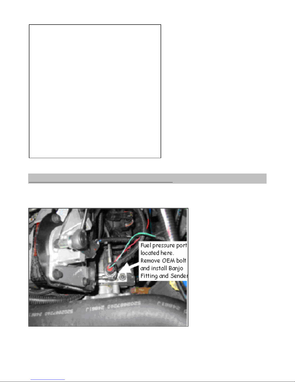
Lift Pump Fuel Pressure (2003-2007)
The sensor mounts on the high-pressure pump located on the driver’s side of the
engine, top/front section. There are two different styles of throttle linkages on the
2003-2007 Dodge Ram pick-ups.
If the throttle linkage is
located near the top of the
engine, remove the
throttle linkage plastic
cover before proceeding.
Once the fuel pressure
port is l
ocated, remove
the existing factory banjo
bolt and install supplied
banjo bolt in X-Monitor kit.
When installation is
complete, run the
engine and check for
leaks.
BD Engine Brake Inc
A10 – 33733 King Rd, Abbotsford, BC, Canada V2S 7M9
Ship: 88 – 446 Harrison St, Sumas, WA 98295 Mail: PO Box 231, Sumas, WA 98295
Ph: 604.853.6096 Fax: 604.853.8749 Internet: www.bd-power.com
Page 16
6 November 2006 1085200/5210/5220 Dodge X-Monitor 16
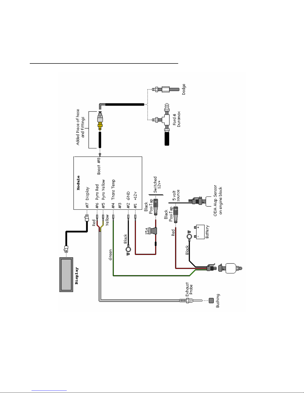
Run the wiring along the driver’s side of the engine and through the firewall near to
the control box and connect the wiring as per the “Lift Pump Pressure” wiring
diagram.
Wiring Diagram – Lift Pump Pressure
BD Engine Brake Inc
A10 – 33733 King Rd, Abbotsford, BC, Canada V2S 7M9
Ship: 88 – 446 Harrison St, Sumas, WA 98295 Mail: PO Box 231, Sumas, WA 98295
Ph: 604.853.6096 Fax: 604.853.8749 Internet: www.bd-power.com
Page 17
6 November 2006 1085200/5210/5220 Dodge X-Monitor 17
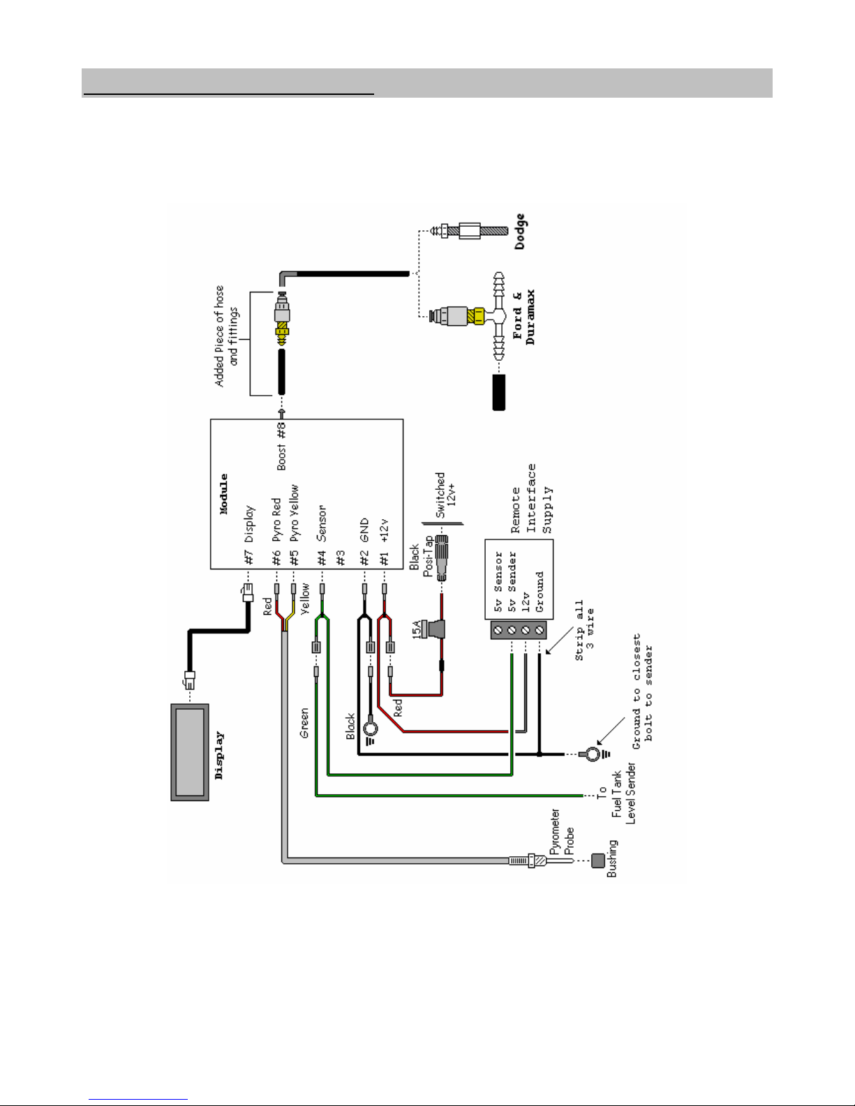
Auxiliary Fuel Tank Level
Consult this diagram for correct hook-up of the auxiliary fuel tank level sender kit.
Notice that the green wire from the control module connects to the output of the
auxiliary fuel tank’s fuel sender. Consult the literature for the sender for the correct
terminal or wire for the output.
BD Engine Brake Inc
A10 – 33733 King Rd, Abbotsford, BC, Canada V2S 7M9
Ship: 88 – 446 Harrison St, Sumas, WA 98295 Mail: PO Box 231, Sumas, WA 98295
Ph: 604.853.6096 Fax: 604.853.8749 Internet: www.bd-power.com
Page 18
6 November 2006 1085200/5210/5220 Dodge X-Monitor 18
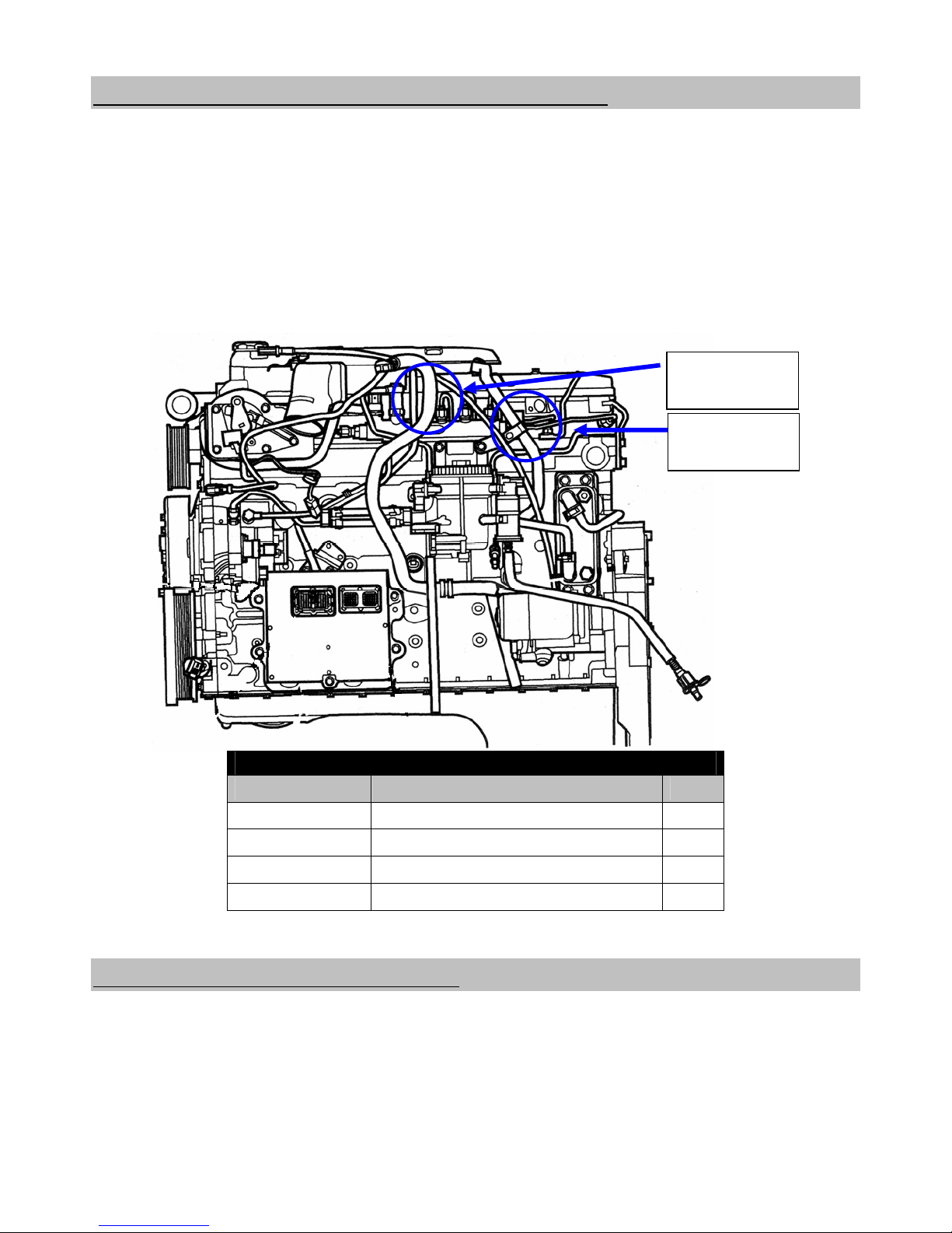
Fuel Pressure Sensor Power and Ground
A 5V source is needed to power the auxiliary fuel pressure sensor. A recommended
location to tap onto is the MAP (Manifold Absolute Pressure) sensor located near
the driver’s side rear portion of the engine block. On 1998½-2002 model trucks it is
located on the side of engine at the rear; on 2003-2007 model trucks it is located on
the top of the engine, near the rear. Use the supplied Posi-Tap to pierce this wire
and use the red wire to route power to the sensor connector assembly.
The ground connection can be routed back towards and connected to the battery.
BD Engine Brake Inc
A10 – 33733 King Rd, Abbotsford, BC, Canada V2S 7M9
Ship: 88 – 446 Harrison St, Sumas, WA 98295 Mail: PO Box 231, Sumas, WA 98295
5 Volt Supply – Located at the MAP Sensor
Model Year Wire Color Pin
1998½-2001 Orange A
2002 Violet w/ White tracer 3
2003 Dark Green w/ Orange tracer C
2004-2007 Pink w/ Yellow tracer C
X-Monitor Power and Ground
Locate a switched 12-volt power source under the dash and install the Red wire to it.
Install the other end to the Power connector of the control box.
Install the Black ground loop to a good ground and install the other end to the
Ground connector of the control box.
1998½-02
MAP
2003-06
MAP
Ph: 604.853.6096 Fax: 604.853.8749 Internet: www.bd-power.com
Page 19

6 November 2006 1085200/5210/5220 Dodge X-Monitor 19
Display Assembly Installation
* * * E X T R E M E C A U T I O N * * *
THE DISPLAY IS VERY FRAGILE AND IS INSTALLED AND TESTED
AT THE MANUFACTURER. IF YOU MUST REMOVE THE DISPLAY IN
ORDER TO PAINT THE PILLAR MOUNT TAKE EXTREME CARE
DURING RE-INSTALLATION. DO NOT OVER-TIGHTEN
THE
MOUNTING SCREWS OR THE DISPLAY WILL BE DAMAGED AND
YOUR WARRANTY WILL BE VOIDED.
A-Pillar Mounts
These mounts go over top of your existing OEM A-Pillar. Place the display assembly
onto the A-pillar to determine the best mounting location and mark this location on
the pillar. Remove the A-pillar for ease of installation.
While holding the display assembly on top of your A-Pillar (in the place where you
would like to mount it), drill 3/16” holes into the corners of the display assembly
mount and through the A-pillar.
Drill a hole through the A-pillar, large enough for the display control wiring connector
to pass through (Optional - This hole is NOT required if you decide to run wiring
along the outside of the A-pillar).
Install
the telephone type communication cable into the back of the display ci
rcuit
board and route the wiring through the drilled hole or along the outside of the pillar
as preferred.
Insert the supplied ratchet fasteners through the drilled holes and into the A-pillar
securing the X-Monitor display assembly to the A-pillar. Install the A-pillar into place
and route the control wiring down to the control box.
Insert the telephone type connector in the socket of the control box. Once all
connections are m
ade, secure the box in place under the dash and away from any
moving parts.
BD Engine Brake Inc
A10 – 33733 King Rd, Abbotsford, BC, Canada V2S 7M9
Ship: 88 – 446 Harrison St, Sumas, WA 98295 Mail: PO Box 231, Sumas, WA 98295
Ph: 604.853.6096 Fax: 604.853.8749 Internet: www.bd-power.com
Page 20

6 November 2006 1085200/5210/5220 Dodge X-Monitor 20
Programming and Set Up
Press both buttons in on the X-Monitor display
and set your ignition into KOEO mode (Key
On / Engine Off). The X-Monitor screen
should light up and after the boot-up has
completed, the words “SIDE OR TOP BTN?”
should appear and the bottom line should read
“SIDE”. Let go of both buttons. Press the
bottom button (if using the A-Pillar mount) to
go to the next screen (if you are installing a universal (top) mount, hit the top button).
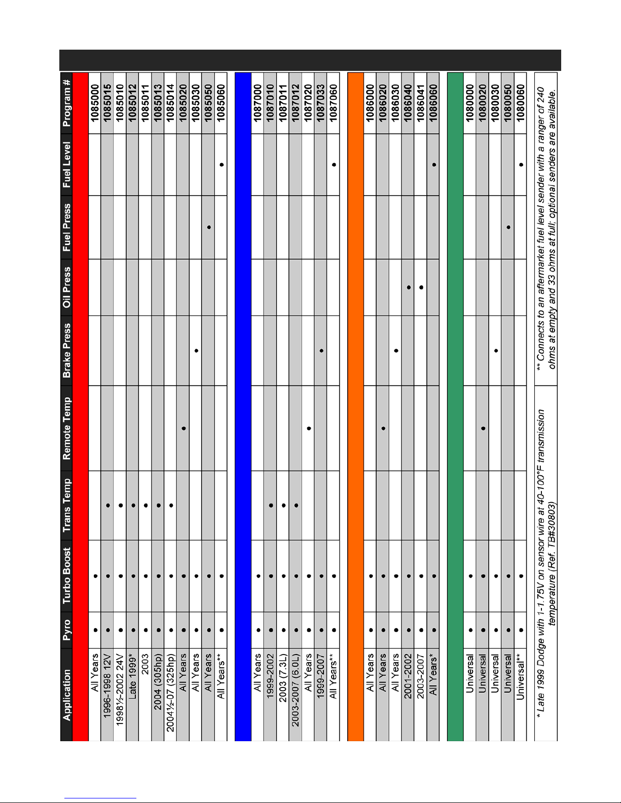
You will now get a screen that will read “PART:” on the top line and “1080000” on
the bottom line. Using the programming chart located on the next page, find the
program number that matches
the application and measurements you are going to
program the X-Monitor for. Press the top button unti
l the program number appears,
then press the bottom button to activate that program (see diagram below). The
display w
ill now cycle through the normal start-up screens that will appear every
time the truck is started.
fter the program has been set, the boot-up screen should displ
ay the following:
A
BD Engine Brake Inc
A10 – 33733 King Rd, Abbotsford, BC, Canada V2S 7M9
Ship: 88 – 446 Harrison St, Sumas, WA 98295 Mail: PO Box 231, Sumas, WA 98295
Ph: 604.853.6096 Fax: 604.853.8749 Internet: www.bd-power.com
Page 21
6 November 2006 1085200/5210/5220 Dodge X-Monitor 21
X-Monitor Programming Chart
BD Engine Brake Inc
A10 – 33733 King Rd, Abbotsford, BC, Canada V2S 7M9
Ship: 88 – 446 Harrison St, Sumas, WA 98295 Mail: PO Box 231, Sumas, WA 98295
Ph: 604.853.6096 Fax: 604.853.8749 Internet: www.bd-power.com
Page 22
6 November 2006 1085200/5210/5220 Dodge X-Monitor 22
Operation
Once the display has gone through the startup cycle it should end up with the
following, default display.
To change the settings and set
alarm values there are 2 buttons
on the side/top of the display: the
bottom (MENU) button cycles
through the different modes and
the top (MODIFY) button controls
the setting of the values.
Recommended Alarm Settings
PYRO 900
TURBO 40
TRANS 200
OIL Dependant on location of sender
B-PSI
User Defined – Consult
Exhaust Brake manual for safe ranges
F-PSI 3
FUEL 25
These are only suggested settings and will vary depending on vehicle condition,
performance enhancements and driving techniques.
NOTES: All temperature readings are in Fahrenheit (°F), pressures are in poundsper-square-inch (PSI) and fuel level is di
splayed in percentages. All readings are
approximate and may vary due to the characteristics of the sensor, sender or probe,
and certain conditions can cause interference or sway the reading.
The alarm settings for fuel pressure (F-PSI), oil pressure (O-PSI) and fuel level
(FUEL) will display an alarm when the measurement drops below the set value; all
other measurements will alarm when the value is above the set value. The history
value also works the same where it records the lowest achieved value on (F-PSI),
(O-PSI) and (FUEL) and the highest value on al
l others.
The X-Monitor is calibrated to the thermocouple that is supplied with the kit and may
not register accurately if an existi
ng or different thermocouple is used. If the
thermocouple was install
e
d post-turbo (in the exhaust pipe), then all temperatures
will indicate to be lower, and the maximum safe temperature would be 900°F.
BD Engine Brake Inc
A10 – 33733 King Rd, Abbotsford, BC, Canada V2S 7M9
Ship: 88 – 446 Harrison St, Sumas, WA 98295 Mail: PO Box 231, Sumas, WA 98295
Ph: 604.853.6096 Fax: 604.853.8749 Internet: www.bd-power.com
Page 23

6 November 2006 1085200/5210/5220 Dodge X-Monitor 23
BD Engine Brake Inc
A10 – 33733 King Rd, Abbotsford, BC, Canada V2S 7M9
Ship: 88 – 446 Harrison St, Sumas, WA 98295 Mail: PO Box 231, Sumas, WA 98295
X-Monitor Display Settings
IN DISPLAY SHUTDOWN MODE:
-Counts down from 9 to shut off display only.
-All functions continue to work in the background.
-Press MENU (lower) button to turn display on.
Ph: 604.853.6096 Fax: 604.853.8749 Internet: www.bd-power.com
Page 24

6 November 2006 1085200/5210/5220 Dodge X-Monitor 24
**CAUTION**: DO NOT RUN ENGINE AT HIGHER THAN 900
DEG INDICATED FOR EXTENDED PERIODS OR ENGINE
DAMAGE MAY RESULT. DO NOT run the transmission higher
than 250 degrees for prolonged periods or transmission
damage may result.
THE X-MONITOR IS A VERSATILE GAUGE PACKAG
E THAT CAN BE
PROGRAMMED TO MONITOR DIFFERENT SYSTEMS OF THE VEHICLE.
THESE INSTRUCTIONS ARE FOR GENERAL INSTALLATION AND SPECIFIC
APPLICATIONS WILL RECEIVE INDIVIDUAL APPLICATION INFORMATION.
NOTE: It is recommended that when mounting/securing the X-Monitor module (or
RPS module used in Back Pressures applications), the barb of the pressure sensor
on the modules point downwards to prevent any condensation from the tubing
collecting inside the modules.
Maintenance & Troubleshooting
Following the diagrams in this manual, tracing hoses and wiring, checking continuity
through electric components or checking for any lines that are disconnected should
solve any problems that may arise.
NOTE: Analog signals are naturally affected by RF (radio frequency) noise. To
eliminate any possible chance of an erratic signal pl
ease choose a clean ground
signal for the X-Monitor, that is clearly mounted away from the alternator wires or
any other voltage sources (positive battery cables, etc.). If for some reason you still
have erratic sensor readings try a direct ground connection to the battery.
Thermocouple wires should also be clear from any RF noise sources as well (i.e.
alternator, positive battery cables, etc.). If the thermocouple signal is erratic then
the copper ground wire that is
contained inside of the lead wire can be connected to
ground to reduce a small amount of noise. Be sure to connect only one end of this
copper wire to eliminate any ground loops from forming.
If you have any problems or need replacement parts, call us at 1-800-887-5030,
between 8:30am and 4:30pm Pacific Time.
BD Engine Brake Inc
A10 – 33733 King Rd, Abbotsford, BC, Canada V2S 7M9
Ship: 88 – 446 Harrison St, Sumas, WA 98295 Mail: PO Box 231, Sumas, WA 98295
Ph: 604.853.6096 Fax: 604.853.8749 Internet: www.bd-power.com
Page 25

6 November 2006 1085200/5210/5220 Dodge X-Monitor 25
BD ENGINE BRAKE, INC.
LIMITED WARRANTY STATEMENT
THE INSTALLATION OF THIS PRODUCT INDICATES THAT THE BUYER HAS READ AND
UNDERSTANDS THIS AGREEMENT AND ACCEPTS ITS TERMS AND CONDITIONS.
DISCLAIMER OF LIABILITY
BD Engine Brake Inc., its successors, distributors, jobbers, and dealers (hereafter “BD”) shall in no way be
responsible
for the product's proper use and service. THE BUYER HEREBY WAIVES ALL LIABILITY
CLAIMS.
BD disclaims any warranty and expressly disclaims any liability for personal injury or damages. BD also
disclai
ms any liability for incidental or consequential damages including, but not limited to, repair labor,
rental vehicles, hotel costs, or any other inconvenience costs by reason of use or sale of any such
equipment. The BUYER acknowledges and agrees that the disclaimer of any liability for personal injury is
a material term for this agreement and the BUYER agrees to indemnify BD and to hold BD harmless from
any claim related to the item of any equipment purchased.
This warranty shall not apply to any unit that has been improperly stored or installed, or to misapplication,
improper operation con
ditions, a
ccidents, neglect, or
which has been improperly repaired or altered or
otherwise mistreated by the BUYER or his agent. BD also assumes no liability regarding the improper
installation or misapplication of its products. It is the installer's responsibility to check for proper installation
and if in doubt, contact the manufacturer.
LIMITATION OF WARRANTY
BD Engine Brake Inc. (hereafter "BD") warrants to the BU
YER that any parts purchased shall be free from
defects in material workmanship. A defect is defined as a condition within the product that would render the
product inoperable. BD gives Limited Warranty as to description, quality, merchantability, fitness for any
product’s purpose, productiveness, or any other matter of BD's product sold herewith. BD shall be in no
way responsible for the product’s open use and service and the BUYER hereby waives all rights other than
those expressly written herein. This Warranty shall not be extended or varied except by a written instrument
signed by BD and the BUYER.
The Warranty is Limited to one (1) year from the date of sale and labor costs incurred by the
removal and replacement of the BD product, w
hile performing warranty work, will be covered for 1
(one) year, payable at BD rates, at authorized centers and with prior approval. Until BD has
approved the claim, the consumer may be responsible for these costs.
A Return Authorization (WA) number, obtained in advance from BD
, must accompa
ny all products returned
for warranty consideration. All products must be returned, shipping prepaid, to BD and must be
accompanied by a dated proof of purchase receipt. All Warranty claims are subject to approval by BD and
repaired or replaced product will be returned to the customer freight collect. Accepted warranty units, which
have been replaced, become the sole property of BD.
This warranty is in lieu of all other warranties or guaranties, either expressed or implied, and shall not
extend to an
y consumer
or to any pe
rson other than the original purchaser residing within the boundaries of
the continental U.S. or Canada.
IN THE EVENT THAT THE BUYER DOES NOT AGREE WITH THIS AGREEMENT, THE BUYER MAY
PROMPTLY
RETUR
N
THIS PRODUCT, IN A NEW AND UNUSED CONDITION, WITH A DATED PROOF
OF PURCHASE, TO THE PLACE OF PURCHASE WITHIN THIRTY (30) DAYS FROM DATE OF
PURCHASE FOR A FULL REFUND.
BD Engine Brake Inc
A10 – 33733 King Rd, Abbotsford, BC, Canada V2S 7M9
Ship: 88 – 446 Harrison St, Sumas, WA 98295 Mail: PO Box 231, Sumas, WA 98295
Ph: 604.853.6096 Fax: 604.853.8749 Internet: www.bd-power.com
 Loading...