

Page 1
TRI-TRAN™ RECEIVER
INSTALLATION INSTRUCTIONS
Part No. 62851
72963 Installation Instructions. Revision 1 September 2008
Thank you for purchasing the B&D Tri-Tran™ plug in two
channel Receiver. Familiarise yourself with the following
instructions prior to commencing set up. Store this information
in a safe place for future reference. The B&D Tri-Tran™
receiver has transistors on board which provide an open
collector contact for controlling virtually any electronic garage
door or gate.
BRAND OF TRANSMITTERS
The first memory location sets the type of transmitters which
can be stored into the receivers memory. It either can be B&D
Tri-Tran™ or ATA TrioCode™ transmitters. For example if first
transmitter stored is TrioCode™ then rest of transmitters can
only be the TrioCode™ type and mixing of TrioCode™ and
Tri-Tran™ is not possible. By deleting all stored transmitter
codes from the receivers memory will allow you to choose either
TrioCode™ or Tri-Tran™ transmitters again.
UNIVERSAL PROGRAMMER
A B&D Universal Programmer can be used to set timer
(adjustable from 0.00 to 655.34 seconds), Edit, back up /
restore transmitters.
STORING TRANSMITTER CODE
1. Press and hold SW1 (for channel 1) or SW2 (for channel
2) on the receiver board. The LED D1 will start to flash.
2. Press the transmit ter button you would like to use to
control the device for two seconds. The LED will start to
flash faster.
3. Release the transmitter button and pause for two
seconds. Press the same button again for two seconds.
The LED will stay on for a second and then turns off.
4. Release SW button.
5. Press the transmitter button to test operation.
DELETING A SINGLE TRANSMITTER’S CODE
1. Press and hold SW1 (for channel 1) or SW2 (for channel
2) on the receiver board. The LED will start to flash.
2. Press the transmit ter button you would like to remove
from receivers memory for two seconds. The LED will
start to flash faster.
3. Release the transmitter button and pause for two
seconds. Press the same button again for two seconds.
The LED will slowly flash two times.
4. Release SW button.
5. Press the transmitter button to confirm that it has been
removed.
DELETING ALL STORED TRANSMITTER CODES
1. Turn the power off to the receiver.
2. Press and hold SW1 button.
3. While holding SW1 turn power on again. After 15
seconds the Coding LED will illuminate to indicate that
the receivers memory has been cleared.
4. Release SW1. All the stored codes should now be deleted.
Confirm this by pressing the transmitters previously used to
operate the device. There should be no response.
COAXIAL CONNECTION
An optional coaxial antenna is available for use with the receiver
in difficult reception areas. The antenna has to be mounted
as high as possible so that it is not obstructed, e.g. on top of a
fence, or on a wall at the front of a garage, etc. Connect the core
of coaxial lead to replace the existing antenna wire (outer screw
socket). Connect shield to the spare (inner) screw socket.
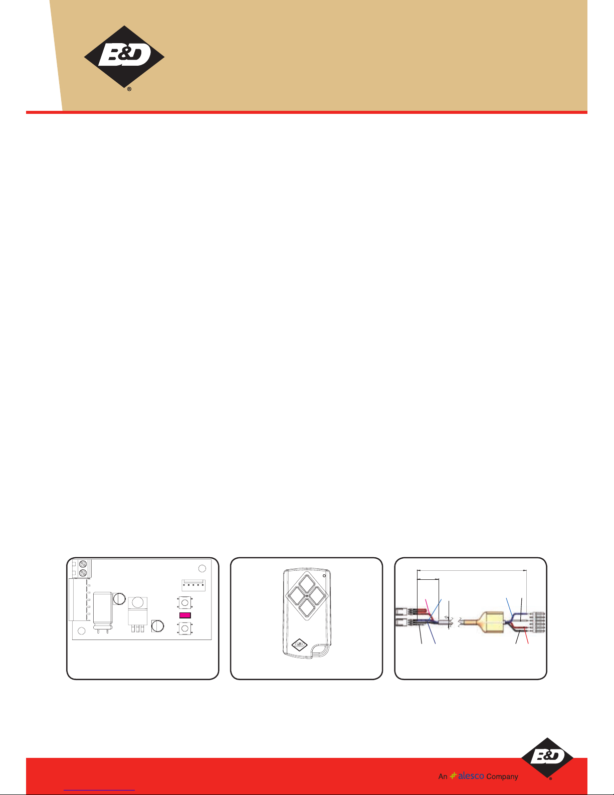
HARNESS
User may have to cut and strip wires to connect to different
openers. Cut and leave white wire if the second channel is not
used.
1
2
3
4
5
6
SW2
SW1
ANTENNA
SHIELD
PG3 CONNECTOR
PIN1 = OPEN COLLECTOR CH1 OUT PUT.
PIN2 = 9 TO 24 VOLT DC INPUT SUPPLY.
PIN3 = NOT USED
PIN4 = OPEN COLLECTOR CH2 OUT PUT.
PIN5 = GROUND. PIN 6 = GROUND.
D1
Tri-Tran
TM
Tri-Tran
TM
Tr ansmitter
RED
RED BLUE
BLACKWHITE
BLUE WHITE
BLACK
5
380
NOM
26 NOM
Harness to use with receiver
Page 2
Tri-Tran™ Receiver Installation Instructions
YOUR REPRESENTATIVE IS
Brisbane:
17 Oasis Court, Clontarf 4019. Phone: (07) 3883 0200
Sydney:
34 Marigold St, Revesby 2212. Phone: (02) 9722 5555
Wollongong:
13-14, Drummond St, Coniston NSW 2500 Phone: (02) 4226 2288
Newcastle:
Unit 1/108 Mitchell Rd, Cardiff NSW 2285 Phone: (02) 4956 8533
Melbourne:
147-153 Caterbury Rd, Kilsyth 3137. Phone: (03) 9237 7766
Adelaide:
23 Frederick Rd, Royal Park 5014. Phone: (08) 8440 4747
Perth:
96 Mulgul Rd, Malaga 6090. Phone: (08) 9247 8777
International/Export:
34 Marigold St, Revesby 2212. Phone: +61 (0)2 9722 5555
B&D Doors Office Locations:
Website: www.bnd.com.au
Prefixed trademarks are the property of B&D Australia Pty Ltd
B&D Doors & Openers is a division of B&D Australia Pty Ltd, an Alesco company
ABN 25 010 473 971
Copyright 2008 B&D Australia Pty Ltd.
SPECIFICATIONS
Power Supply: 9 volts to 24 Volts DC ONLY
Frequency: Multi frequency
Memory Capacity: 250 Transmitters
Control Output 1 : Open collector output at pin one for channel one (40 dc volts 100ma max)
Control Output 2 : Open collector output at pin four for channel two (40 dc volts 100ma max)
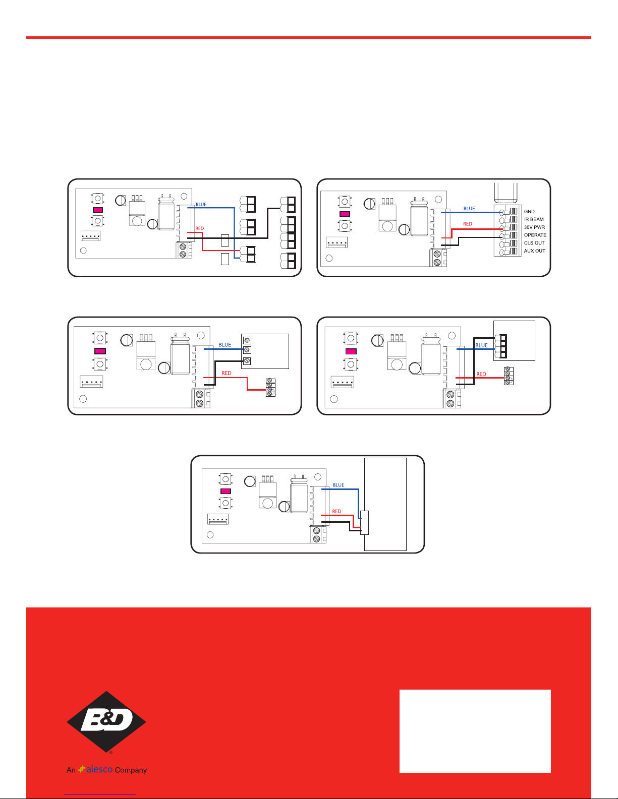
HOW TO CONNECT RECEIVER WITH HARNESS TO OPENERS:
6
5
4
3
2
1
SW2
SW1
SHIELD
ANTENNA
PG3 CONNECTOR
D1
BLACK
6
5
4
3
2
1
SW2
SW1
SHIELD
ANTENNA
CONNECTING RECEIVER TO CONTROLL-A-DOOR P DIAMOND
CONNECTING RECEIVER TO CONTROLL-A-DOOR
DIAMOND - POWER DRIVE
PG3 CONNECTOR
D1
-24V
+24V
-24V
+24V
BLACK
CONNECTING RECEIVER TO CONTROLL-A-DOOR 4 CONNECTING RECEIVER TO CONTROLL-A-DOOR P
6
5
4
3
2
1
SW2
SW1
SHIELD
ANTENNA
PG3 CONNECTOR
D1
Internal
Connecto
24V
OSC (red)
COM(white)
BLACK
6
5
4
3
2
1
SW2
SW1
SHIELD
ANTENNA
PG3 CONNECTOR
D1
Internal
Connector
24V
2
Common
1
OSC
3
BLACK
CONNECTING RECEIVER TO CONTROLL-A-DOOR R
6
5
4
3
2
1
SW2
SW1
SHIELD
ANTENNA
PG3 CONNECTOR
D1
059620 PCB Assy
Bottom side
1 2 3 45
J1
BLACK
 Loading...