

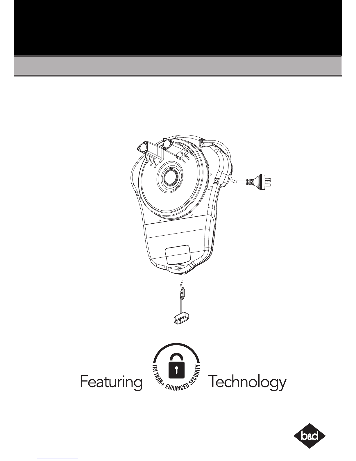
B&D Controll-A-Door TB-6, Controll-A-Door RDO-1V4, Roll-A-Pro RDO-1V3, Roll-A-Pro TB-5, Controll-A-Door Power Drive Instruction Manual
...Page 1
1
Controll-A-Door® Power Drive & Roll-A-Pro® Instruction Manual
Controll-A-Door® Power Drive
& Roll-A-Pro
®
Doc #: 161040_00
Part #:79129
Released: 04/08/2016
Rolling Door Opener
Instruction Manual
Page 2

Controll-A-Door® Power Drive & Roll-A-Pro® Instruction Manual
2
Table of Contents
1. Installation Safety Warnings! 3
2. Kit Contents 4
3. Tools Required 4
4. Setup Requirements 5
The Opener: 5
Unsuitable Door Types 5
Sideroom 5
5. Door Preparation 6
6. Fit the Weight Bar 6
If the door has a handle: 6
If the door does not have a handle: 6
7. Pinning the Door 7
8. Proping the Door 7
9. Mounting the Opener 8
10. Setting the Travel Limits 9
Initial Preparation: 9
Set the Limit Positions: 9
Resetting the Door Limit Positions 9
Setting the PET Mode position 9
Reset all Factory Defaults 9
11. Safety Testing 10
Test the Close Cycle 10
Testing the Open Cycle 10
Test the Manual Door Operation 10
Adjusting Safety Obstruction Force 10
To Increase Force Pressure 10
To Decrease Force Pressure 10
To Recall Factory Set Force 10
To Recalculate Force Margins 10
12. Accessories 11
Auxiliary Output 11
Keyswitch Connection 11
Remote Aerial 11
13. Auto-Close (CAD PD Only) 11
Safety Beams 11
Auto Close Option 11
14. Coding a Transmitter 12
Storing the Transmitter Code 12
Coding a Transmitter to the Courtesy Light 12
Coding Vacation Mode 12
Coding to enable AUX Output 12
Setting the Transmitter to Operate PET Mode 13
Installation of the Wall Mounted Transmitter 13
Remotely Coding Transmitters 13
Erasing Programmed Codes 13
Installation Instructions
Home Owner Instructions
15. Home Owner Safety Warnings! 14
16. Opener Safety & Security 15
Your Door CAN NOT be used when: 15
Your Door CAN be used when: 15
To Disengage the Opener: 15
To Re-Engage the Opener: 15
17. Operating your Opener 15
18. User Operating Controls 16
19. Door Status Indicators 16
20. Specifications 17
21. Troubleshooting 18
22. Maintenance 20
23. Battery Replacement 20
24. Battery Disposal 20
25. Service Schedule 21
26. Warranty 22
27. Optional Accessories 23
Page 3
3
Controll-A-Door® Power Drive & Roll-A-Pro® Instruction Manual
1. Installation Safety Warnings!
WARNING!
• The door may operate unexpectedly, therefore do not allow anything to stay in the path of
the door.
• When operating the manual release while the door is open, the door may fall rapidly due
to weak or broken springs, or due to being improperly balanced.
• The drive must not be used with a door incorporating a wicket door, unless the drive cannot
be operated with the wicket door open.
• The drive is intended to be installed at least 2.5m above the floor.
• Do not disengage the opener to manual operation with children/persons or any objects
including motor vehicles within the doorway.
• If the door is closing and is unable to re-open when obstructed, discontinue use. Do not
use a door with faulty obstruction sensing
• When using auto close mode, a Photo Electric beam must be fitted correctly and tested
for operation at regular intervals. Extreme caution is recommended when using auto
close mode. All safety rules must be followed.
ELECTROCUTION!
• Place opener in protected area so that it does not get wet.
• Do not spray with water .
• Disconnect the power cord from mains power before making any repairs or removing
covers. Only experienced service personnel should remove covers from the opener.
• If the power supply cord is damaged, it must be replaced by an Automatic Technology
service agent or suitably qualified person.
• Connect the opener to a properly earthed general purpose 240V mains power outlet
installed by a qualified electrical contractor.
CAUTION:
Emergency Access • If garage has no pedestrian entrance door, an emergency access device should be
installed. This accessory allows manual operation of the garage door from outside in case
of power failure.
Muscular strain • Practice correct lifting techniques (carton weighs approx 9kgs)
• Practice correct lifiting techniques when required to lift the door as per installation instructions.
Fall from ladder • Ensure ladder is the correct type for job.
• Ensure ladder is on flat firm ground that will take the weight without the legs sinking.
• Ensure user has 3 points of contact while on ladder.
Crush injury from unsecured
door
• Place a 2 metre exclusion zone around area under the door while it is unsecured.
• Do not move under a door while it is on the door support (or ladder)
• Follow the installation instructions
• Fit door support (or ladder) snugly under door before removing bracket.
• Ensure door support (or ladder) is on flat ground
Garage Door • Examine the door installation, in particular, springs and mountings for signs of wear, damage
and imbalance.
• The garage door must be well balanced. Sticking or binding doors must be repaired by a
qualified garage door installer prior to installation of the opener.
• Remove or disengage all garage door locks and mechanisms prior to installation of the
opener.
Entanglement • Never plug in and operate opener prior to installation.
• Keep hands and loose clothing clear of door and guides at all times.
Entrapment under
operating door
• DO NOT operate the opener unless the garage door is in full view and free from objects
such as cars and children/people. Make sure that the door has finished moving before
entering or leaving the garage
• In order for the opener to sense an object obstructing the door way, some force must be
exerted on the object. As a result the object, door and/or person may suffer minor damage
or injury.
• Ensure the garage door is in good working order by undertaking regular servicing.
• Install the optional wall transmitter in a location where the garage door is visible, but out of
the reach of children at a height of at least 1.5m.
• Photo Electric beams must be installed if the closing force at the bottom edge of the door
exceeds 400N (40kg)
This automatic garage door opener is designed and tested to offer safe service provided it is installed
and operated in strict accordance with the following safety warnings. Failure to comply with the following
instructions may result in death, serious personal injury or property damage.
Page 4
Controll-A-Door® Power Drive & Roll-A-Pro® Instruction Manual
4
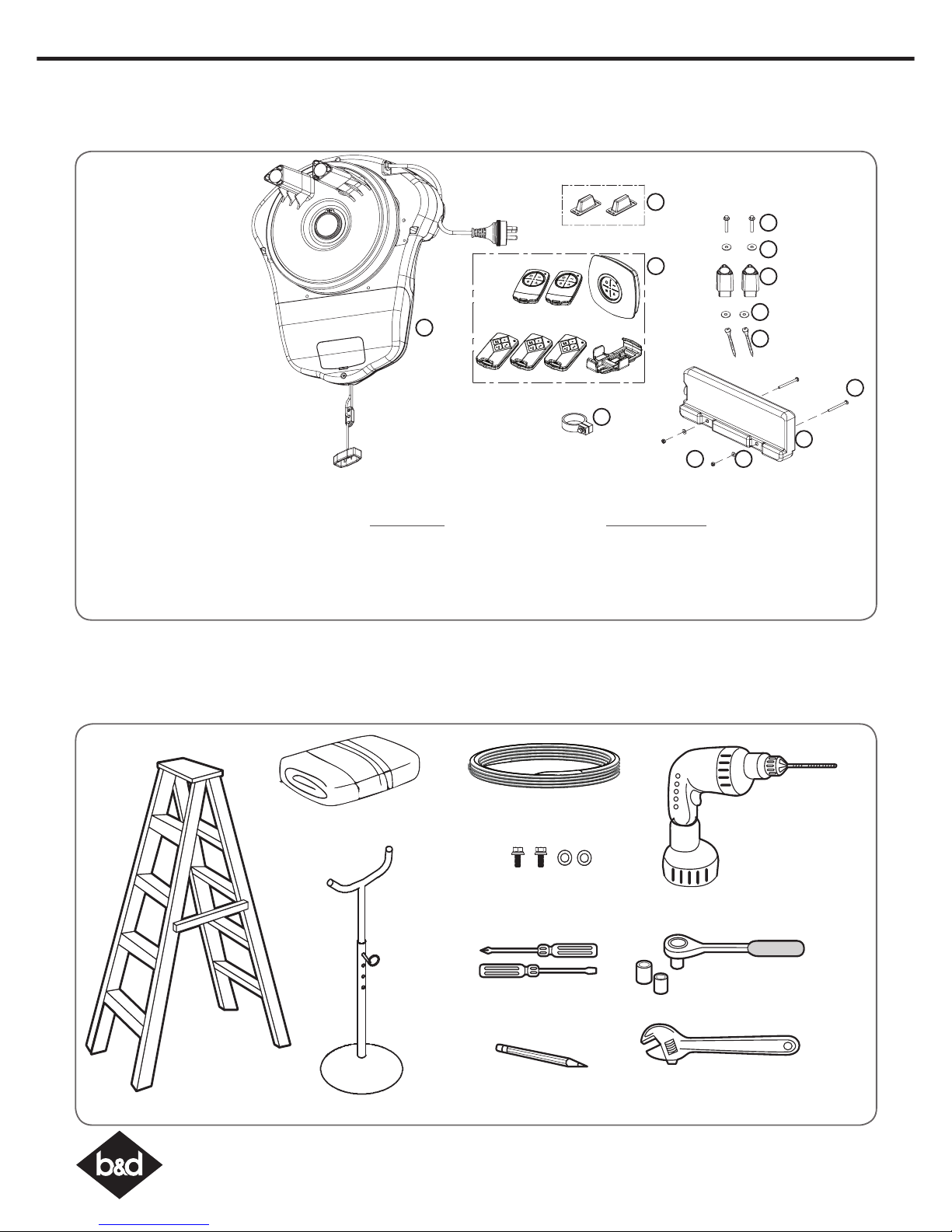
2. Kit Contents
OR
1. Power Drive 1 x RDO-1V4 drive unit
OR
Roll-A-ProTM 1 x RDO-1V3 drive unit
2. 2 x Locking Bar Covers
3. Power Drive 2 x TB-6 Transmitters
1 x Wall Mount Transmitter
OR
Roll-A-ProTM 3 x TB-5 Transmitters
1 x Wall / Visor Clip
4. 1 x Collar Kit
5. 1 x Weight Bar
Fastner Bag
6. 2 x Nilock Nut
7. 2 x 2 x 3/16 x 1/2 flat washers
8. 2 x Pan Head Screw M4 x 50
9. 2 x Self Tapping Screw M10 x 32
10. 2 x Washer 6.4 x 20.6 x 1.2 GAL
Accessory Pack
11. 2 x Extension Fork
12. 2 x Flat Washer 107D 6.4 x 20.5 x 1.6
13. 2 x Hex Serration Head Screw M6 x 45
1
2
3
5
6 7
8
13
12
11
9
4
10
Screwdrivers
Adjustable End Wrench
Sockets and Wrench
Pencil
Rope
Drill
Towel
Screws and Washers
(M10 x 32mm)
Stepladder
Door Stand
or suitable prop
3. Tools Required
Page 5
5
Controll-A-Door® Power Drive & Roll-A-Pro® Instruction Manual
WARNING! A portable power generator is
not recommended due to spikes, surges
and fluctuations in the supply.
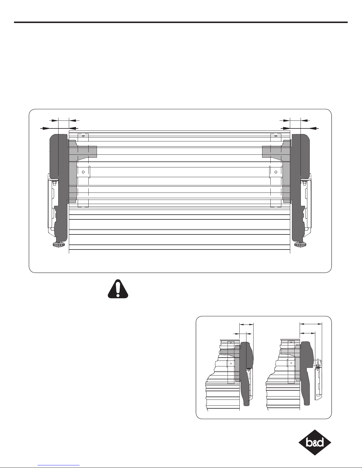
85
41
135
95
Minimum Side room Recommended Side room
Unsuitable Door Types
The drive must not be used with a door incorporating a wicket
door, unless the drive cannot be operated with the wicket door
open. The fitting of an opener to doors with removable mullions is
not recommended.
Sideroom
The minimum sideroom required from the edge of the door
curtain is 41mm to the inside of the door bracket, and 85mm to
the wall. If a Battery Backup is to be fitted, at least 135mm to the
bracket is required.
Therefore the recommended sideroom from the edge of the door
curtain is 95mm to the inside of the door bracket, and 135mm to
the wall as per diagram.
4. Setup Requirements
The Opener:
a. MUST BE installed in a dry position, protected from weather. (Moisture or corrosion not covered by Warranty)
b. Is factory set for RIGHT HAND SIDE installation (from inside garage), but capable of LEFT HAND SIDE installation.
c. REQUIRES properly earthed 3 pin single phase power within an arms length of door and at a suitable height
d. Requires a MINIMUM SIDEROOM of 41mm from the edge of the door to the inside of the door bracket and 85mm to the
wall.
e. CAN NOT be installed on a Door Axle Diameter that exceeds 35mm.
LEFT HAND SIDE RIGHT HAND SIDE
40mm
40mm
85mm
85mm
Page 6
Controll-A-Door® Power Drive & Roll-A-Pro® Instruction Manual
6
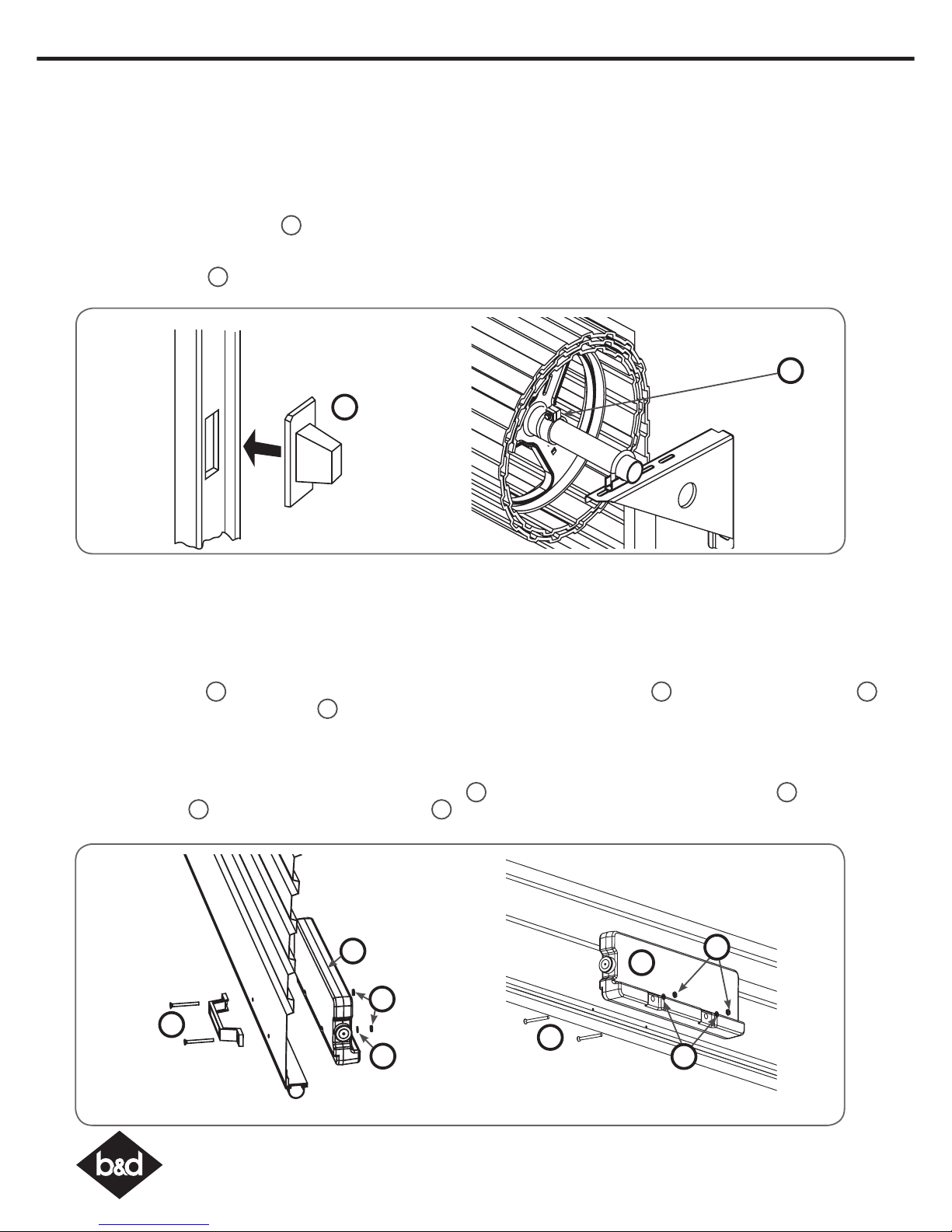
If the door has a handle a weight bar must be fitted to ensure the door doesn’t balloon during operation:
a. Remove the door handle
b. Fit the weight bar 5 and refit the handle using the two (2) M4x50mm Pan Head Screw 8 and the two (2) Flat Washer 7
and the two (2) M4 Nilock Hex nut 6.
If the door does not have a handle:
a. Locate the centre of the door at the bottom rail.
b. Place the weight bar at this point and mark the two positions where the fasteners will go
c. Drill the two 4.5mm holes in the door and fit the weight bar 5 using the two (2) M4x50mm Pan Head Screw 8 and the two
(2) Flat Washer 7 and the two (2) M4 Nilock Hex nut 6.
d. Check that the door is still balanced and smooth. If not, then the door may require servicing.
5
2
8
5. Door Preparation
Prepare the Door:
a. Clean the guides if there is any oil or wax present using a suitable white spirit. The only lubricant suitable for use on door guides
is silicon spray. DO NOT use WD-40, RP-7, petroleum grease, or similar.
b. Remove the locking bars or disable the lock.
c. Install the locking bar covers 2 if there are locking bar holes in the guides. This ensures fingers cannot be placed in the
holes while the door operates
d. Affix the supplied warning labels where they are clearly visible on the inside of the door.
e. Install the collar kit 4 to the OPPOSITE end to where the opener is being installed.
f. Fit the collar kit hard up against the drum.
6. Fit the Weight Bar
WITH HANDLE WITHOUT HANDLE
6
7
5
8
6
7
4
Page 7
7
Controll-A-Door® Power Drive & Roll-A-Pro® Instruction Manual
7. Pinning the Door
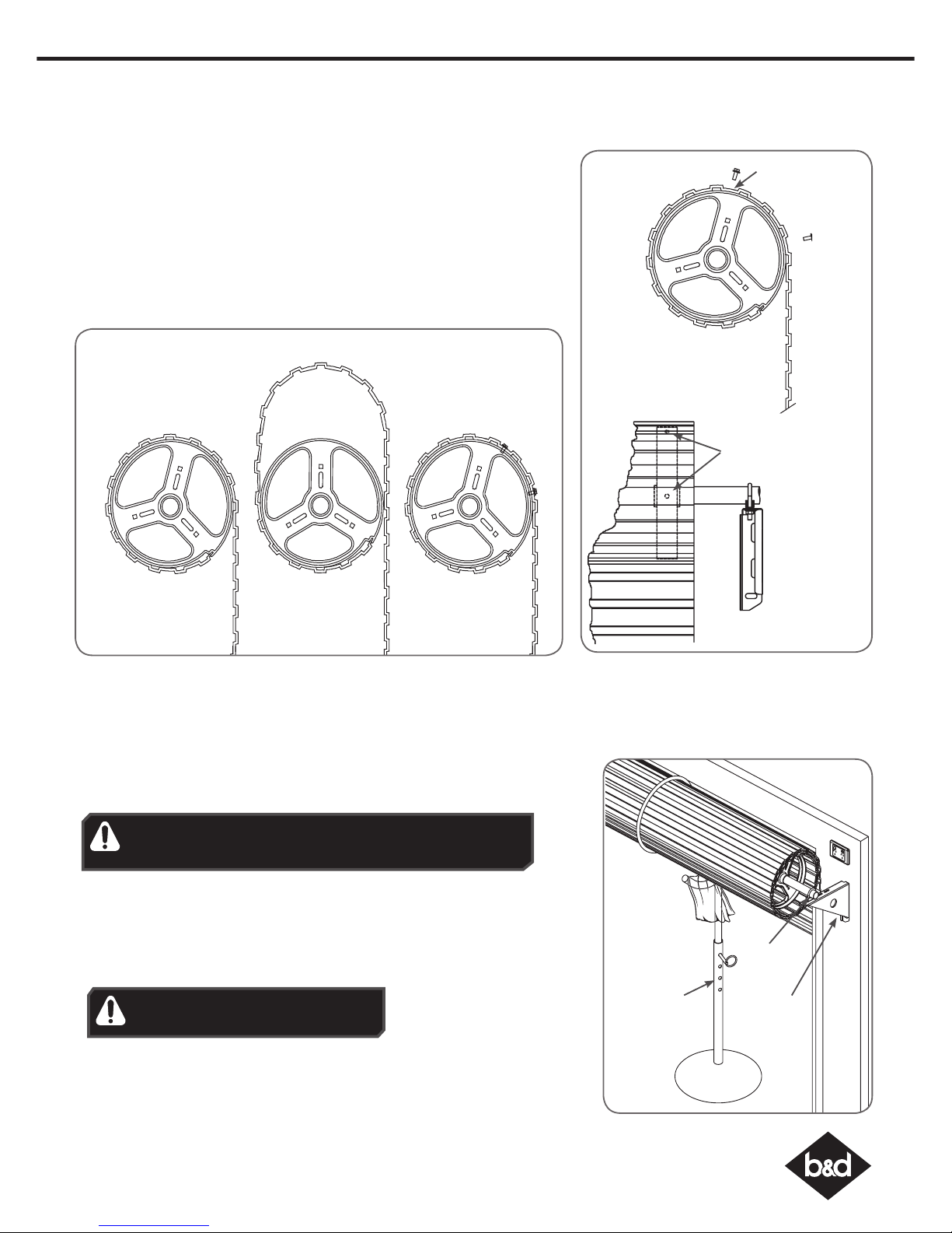
Pinning the Door to the drum:
Pinning the door’s curtain to its drum maintains security when the opener is
closed. If the curtain is not pinned the door can be partially opened manually.
a. Fully close the door.
b. Mark a minimum of two (2) drill holes on the drum to each end of the door.
c. Drill holes using 3.2mm (1/8”) drill bit.
d. Fit M10 x 32mm screws and washers (not supplied) to each of the four (4)
holes. This screw should be positioned as low as possible in the grove, but
make sure that it does not alter the curtain’s normal lead in to the guide.
BALLOONING DOOR
PINNED DOORFREE DOOR
Without locking
bars door can be
lifted
Without locking
bars door can be
lifted
Door secure and
will not lift
Pin Points
Screw into the
low part of
grove
8. Proping the Door
Prepare the Door:
a. At the end opposite to where the opener will be fitted, check that the U-bolt
which holds the door axle to the bracket is tightened securely.
b. Open the door completely and tie rope around the door roll. Do not tie the
rope too tight as damage to the curtain may ensue. This will stop the door
unrolling when taken off the bracket
c. At the end where the opener is to be fitted, support the door with a door stand
or suitable prop. Place a towel between the door and the prop to protect the
door from damage.
d. At the end where the opener will be fitted use a pencil to mark the position of
the U-bolt in the door bracket and the position of the door bracket on the wall
to assist in reassembling.
WARNING! The U-bolt must be done up tightly to ensure
the stored energy in the springs cannot be unexpectedly
released.
WARNING! Make sure the prop is snug
under the door and is stable.
U-bolts
Towel
Door stand
or prop
Door
bracket
Page 8
Controll-A-Door® Power Drive & Roll-A-Pro® Instruction Manual
8
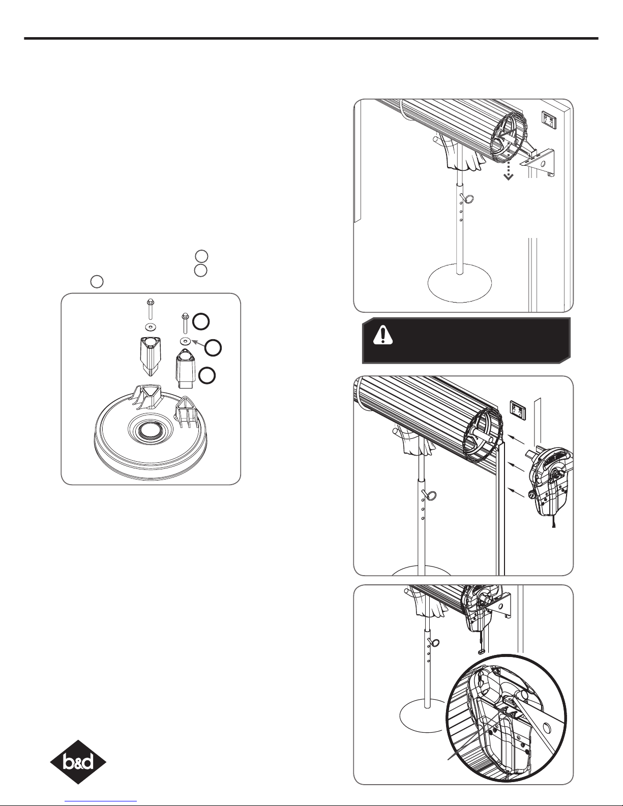
Raising the Door:
a. When in position, remove the U-bolt (or bolts) and saddle from the
door bracket.
b. Lift the door up and away from the wall until clear of the door
bracket, before lowering the door to rest on the door stand or prop.
NOTE: If there is limited ceiling space to lift the door, the door bracket
may have to be removed. If this is required, when refitting the door
bracket , use the reference marks on the wall for correct position and
ensure that it is secure to the wall and will support the door.
9. Mounting the Opener
Lift door
up, away
from wall
and down
onto prop
WARNING! For tight sideroom
installations the door may have to be
taken down.
Mounting the Opener:
a. Remove the opener from the box.
b. Insert the two (2) Extension forks 11 into the ring gear.
c. Secure with two (2) Flat washers 12 and two (2) Hex serration head
screws 13.
Tighten
U-bolts
Pull string
down to
disengage
opener
Slide
opener
over door
axle
d. Check the drive gear rotates freely, by pulling the string handle
down (there will be a click) to disengage opener. Then move the
forks from side to side by hand.
e. Slide the opener over the door axle and into the drum of the door
as shown.
f. Push the opener in as far as possible (without interfering with the
curtain) so one of the door drum’s wheel spokes is between the
opener’s drive forks.
g. Raise the door off the door stand or suitable prop.
h. Lift up and over the door bracket and use your reference marks on
the door bracket to position the door.
i. Refit the U-bolt and nuts and tighten.
j. Remove the safety rope and door stand or prop.
k. Connect the power cort to a suitable powerpoint, but DO NOT
switch on.
l. Secure the power cord away from any moving object (e.g the
door) with the cable clip supplied.
m. With the opener still disengaged, pull the door up and down to
make sure it runs freely.
13
12
11
Page 9
9
Controll-A-Door® Power Drive & Roll-A-Pro® Instruction Manual
10. Setting the Travel Limits
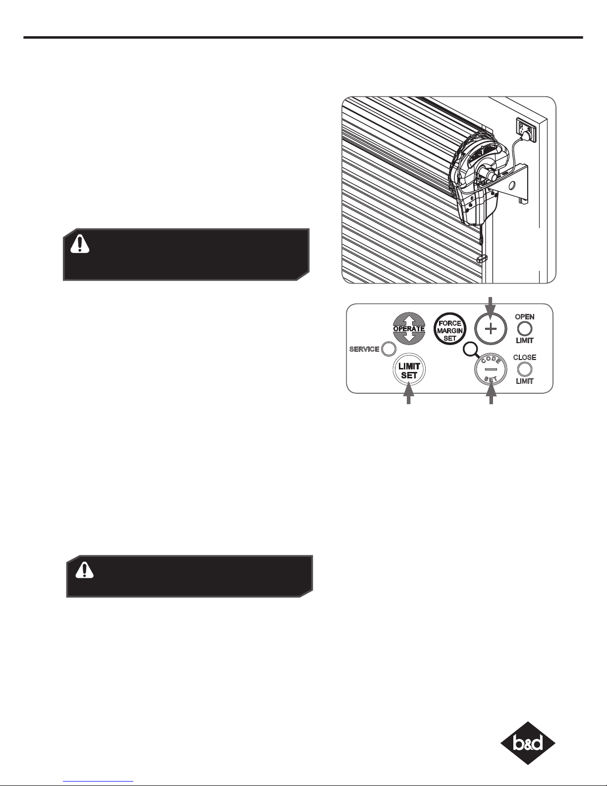
Initial Preparation:
a. Move the door to the half way position.
b. Remove the clear button cover from the unit.
c. Engage the opener by pulling down on the manual release
string until a click sounds.
d. Switch power on to the opener. The red CLOSE LIMIT LED will be
flashing.
e. Press and hold the MINUS (-) button - the door should start
closing.
NOTE: If the door opens, release the MINUS (-) button and press
the OPERATE button once to change the motor’s direction.
Pull string
down to
engage
opener
Set the Limit Positions:
The Limit Positions can vary due to site conditions, such as uneven
ground. When setting the Close limits, ensure the position is when
the door makes first contact with the ground. Alternatively for the
Open limits the position should be at the height of the garage
opening.
a. Press and hold MINUS (-) button until the door reaches your
desired close limit position. The rubber strip at the bottom of
the door should form a good seal with the ground.
b. Release the MINUS (-) button when the door is near the desired
closed position. Single presses of the MINUS (-) button will inch
the door closer to the ground.
c. If the door overshoots press the PLUS (+) button to move the
door in the open direction.
d. When the door is at the desired close position, press the LIMIT
SET button, the OPEN LIMIT LED will now flash.
e. Press and hold the PLUS (+) button until the door reaches your
desired open limit position. Single presses of the PLUS (+) button
will inch the door open.
f. If the door overshoots press the MINUS (-) button to move the
door in the close direction.
g. When the door is at the desired open position, press the LIMIT
SET button.
WARNING! In setting the close limit position, do not
force the door into the floor with excessive force,
as this can interfere with the ease of operation of
the manual release mechanism.
h. The door will now automatically close and open to calculate
the safety obstruction settings.
Resetting the Door Limit Positions
Limit positions can be deleted by:
a. Press and hold LIMIT SET button for six (6) seconds until the CLOSE
LIMIT LED flashes quickly.
b. Release the LIMIT SET button.
NOTE: If no action is taken within 30 seconds, the opener will return
to normal operating mode and restore the original settings.
c. Follow steps a - f in Set the Limits Poisitions to set new limit
positions.
WARNING! The door will automatically close,
open and close again after the next step. Ensure
that nothing is in the door’s path.
Setting the PET Mode position
When activated, PET mode drives the door to a preset
position from the close position, therefore allowing a pet
or parcel to go under the door.
a. Drive and stop the door at the deisred PET mode open
position by pressing the transmitter button coded for
Open/Stop/Close operation.
b. Press and hold the PLUS (+) button on the opener for
six (6) seconds until the OPEN and CLOSE LED’s are lit to
record the new PET position.
c. Release the PLUS (+) button.
Reset all Factory Defaults
a. Turn power to the opener off.
b. Press and hold the LIMIT SET Button.
c. Turn power on while holding the LIMIT SET button.
Continue to hold until all LED’s are off.
d. This will not erase transmitter codes stored in memory.
Page 10
Controll-A-Door® Power Drive & Roll-A-Pro® Instruction Manual
10
11. Safety Testing
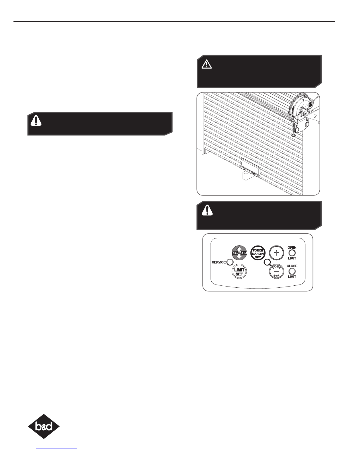
Test the Close Cycle
a. Press the OPERATE button to open the door.
b. If the door closes, press the OPERATE button to stop the door, then
press OPERATE again to open.
c. Place a piece of timber approximately 40mm high (or the openers
cardboard box) on the floor directly under the door.
d. Press the OPERATE button to close door.
e. The door should strike the object and re-open.
f. Remove the timber or cardboard box.
Testing the Open Cycle
a. Press the OPERATE button to close the door.
b. Press OPERATE again to open the door.
c. When the door reaches approximately half way, firmly grab the
door’s bottom rail - the door should stop.
If the door does not reverse readily when closing, or stop when
opening, put the door into manual by pulling down on the manual
release string to diesengage the motor and contact 1300 300 625
for support.
Test the Manual Door Operation
Periodically disengage the opener and manually operate the door.
The door must be smooth to operate by hand. The force required on
the bottom rail should not exceed 15 kg.
CAUTION: Take care when completing a
safety test. Failure to follow this warning
can result in serious personal injury and/or
property damage.
WARNING! If the door is closing and is unable
to re-open when obstructed, discontinue use.
Do not use a door with faulty obstruction sensing.
Wood 40mm
high or opener
cardboard box
To Recall Factory Set Force
a. Holding down the FORCE MARGIN SET button and
the LIMIT SET button for two seconds.
b. Release both buttons. The default setting should
now be recalled.
To Recalculate Force Margins
a. Press and hold the FORCE MARGIN SET Button for six
(6) seconds, the beeper will sound once.
b. The door will start to move and re-calculate
force margins. The door can move between the
open and close limit positions up to four (4) times
(depending on the position of the door and the
power up condition).
c. A single beep will be heard once the process is
complete.
d. Test the force again as per Testing Close Cycle and
Testing Open Cycle.
Adjusting Safety Obstruction Force
The Safety Obstruction Force is calculated automatically during
setup. Adjusting this is normally only necessitated by environmental
conditions such as windy or dusty areas, and areas with extreme
temperature changes.
To Increase Force Pressure
a. Hold down the FORCE MARGIN SET button.
b. While holding the FORCE MARGIN SET button, press the PLUS (+)
button. Each press will increases the force margin.
c. The OPEN LIMIT LED will flash each time the PLUS (+) button is
pressed to indicate an increase in force.
d. If the OPEN LIMIT LED flashes continuously when the PLUS (+) button
is being pressed, this indicates that the maximum force setting
has been reached.
e. Test the force again as per Testing Close Cycle and Testing Open
Cycle.
To Decrease Force Pressure
a. Hold down the FORCE MARGIN SET button.
b. While holding the FORCE MARGIN SET button, press the MINUS (-)
button. Each press will decrease the force margin.
c. The CLOSE LIMIT LED will flash each time the MINUS (-) button is
pressed to indicate a decrease in force.
d. If the CLOSE LIMIT LED flashes continuously when the MINUS (-)
button is being pressed, this indicates that the minimum force
setting has been reached.
e. Test the force again as per Testing Close Cycle and Testing Open
Cycle.
WARNING! If the door fails these tests,
put the opener into manual mode, only
operate the door by hand and call for
service.
Page 11
11
Controll-A-Door® Power Drive & Roll-A-Pro® Instruction Manual
12. Accessories
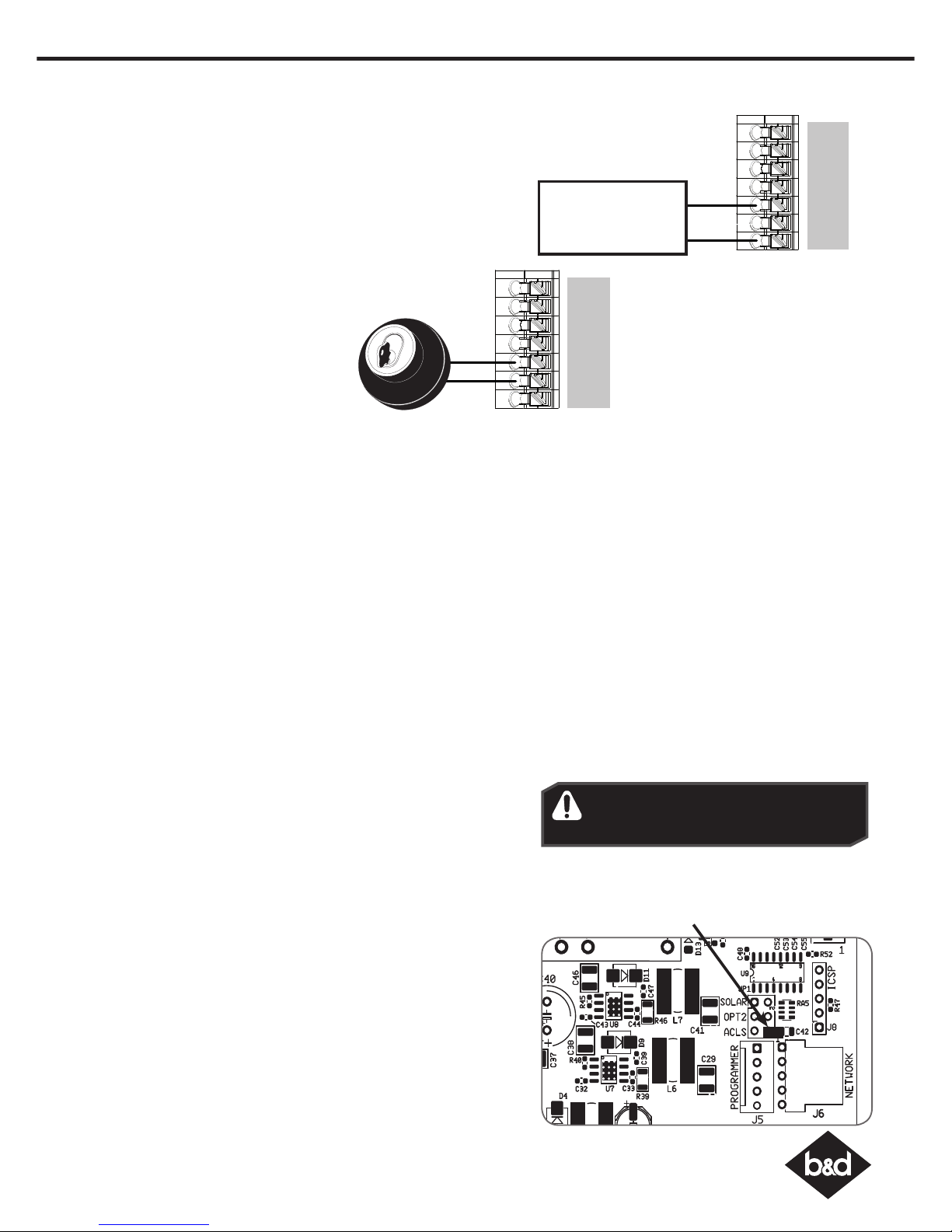
Auxiliary Output
The auxiliary output can be used to control alarm or another garage
door opener. A valid transmission from the pre-coded transmitter will
cause the auxiliary output to pulse for approximately 1 (one) second.
The maximum DC voltage must not exceed 35 volts DC. Maximum
current must not exceed 80 ma.
V+
EB1
0V
EB2
0V
OSC
AUX
External device,
Alarm, Door or
Gate opener.
V+
EB1
0V
EB2
0V
OSC
AUX
Remote Aerial
Some sites cause poor radio reception. Particularly problematic areas are those where there is a large amount of metal, like a
steel garage, or an underground car park with large masses of steel reinforced concrete. These issues, and others, can create
reception issues.
Poor radio reception will be noticed by a reduction in the operating range of the transmitters.
You can evaluate whether fitting an external aerial will benefit as follows;
i. Test the maximum operating range of the transmitter with the garage door closed; then
ii. Test the maximum operating range of the transmitter with the garage door open.
If the range improves when the door is open you can install a remote aerial kit to improve reception.
Mount the aerial to a suitable location on the outside of the garage.
Similar to a television aerial, the better the mounting position the better the reception will be. Where possible, mount the aerial
as high as possible, away from masses of metal and in line of sight position, to where you normally use your transmitter.
Keyswitch Connection
The RDO-1V4 has the input to connect
bell switch or keyswitch to open or close
the door.
Safety Beams
A Safety Beam Kit may be fitted to this opener. When this option is
fitted, the operation of this device is such that if an object (i.e car,
child etc) blocks the Infra-Red beam, then the garage door opener
will not close the door automatically. If the Safety Beam is fitted but
not operating coreectly, then the door once opened automatically,
will not close automatically.
Auto Close Option
Auto-Close mode is a function that automatically closes the door a
preset time after the Safety Beams recognise that a vehicle has left
the garage. The Auto-Close timer only starts after the Safety Beam’s
path is broken. If the safety beam path is not broken, the door will
remain open until the path is broken. If the opener incurs a physical
obstruction (i.e. not from the Safety Beams) while closing the door, it
will re-open and not Auto-Close until the Safety Beam’s path is broken
again.
To enable the Auto-Close function remove the light diffuser from the
opener and remove the AUTO-CLS (ACLS) shunt next to the programmer
input and place over both ACLS inputs. When this option is selected
the garage door opener will attempt to close the door automatically
30 seconds after opening. Refit the light diffuser.
13. Auto-Close (CAD PD Only)
WARNING! It is compulsory to have
Safety Beams installed when using
Auto-Close mode.
Remove shunt
and place over
both inputs.
Page 12
Controll-A-Door® Power Drive & Roll-A-Pro® Instruction Manual
12
14. Coding a Transmitter
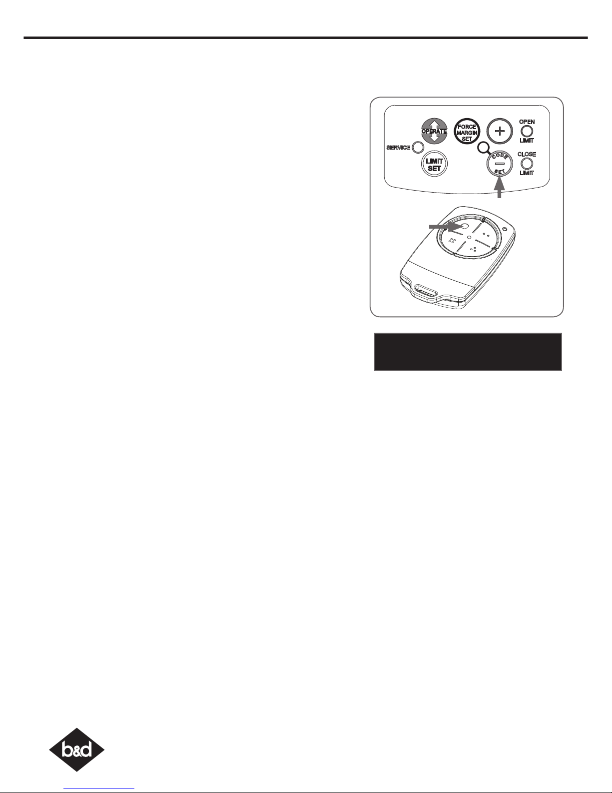
Storing the Transmitter Code
The opener can only operated from remote control transmitters that have
been programmed into its memory. Up to 64 codes can be stored in the
memory.
a. Press the CODE SET button and release. The CODE SET LED will illuminate
to indicate the opener is in Code Learn mode. If a valid code is not
stored within 15 seconds the opener will exit Code Learn.
b. Press the transmitter button one (1) to control the door. The
CODE SET LED will flash.
c. Press the same transmitter button again. The CODE SET LED will illuminate
for one second then go out.
d. The transmitter button is now coded - press to test.
Coding a Transmitter to the Courtesy Light
The transmitter can be programmed to operate the courtesy light on the
opener independently of the door moving.
a. Press the CODE SET button twice - the CODE SET LED and courtesy light
will both illuminate.
b. Press one of the four buttons on the transmitter for two (2) seconds,
pause for two (2) seconds, then press the same button again for two (2)
seconds.The CODE SET LED will illuminate for one second then go out.
c. Press the transmitter button to test.
Coding a Transmitter Button to Enable Vacation Mode
The opener can be programmed into a “Vacation Mode” where the opener
will not respond to any transmitter except the button of the transmitter that
was programmed for vacation mode.
a. Press the CODE SET button three (3) times - the CODE SET LED will illuminate
and the courtesy light will flash slowly.
b. Press one of the four (4) buttons on the transmitter for two (2) seconds,
the CODE SET LED will begin to flash, pause for two (2) seconds, then
press the same button again for two (2) seconds.
c. The CODE SET LED will illuminate for one second and then go out, and
the courtesy light will also switch off. This indicates the code has been
stored.
d. Press and hold the transmitter button for five (5) seconds to set Vacation
Mode. The CODE SET LED will stay lit while Vacation Mode is active.
e. To reset Vacation Mode, press the same button for two seconds, until the
CODE SET LED turns off.
Coding a Transmitter to enable AUX Output
a. Press the CODE SET button four (4) times - the CODE SET LED will illuminate
and the courtesy light will flash quickly.
b. Press one of the four (4) buttons on the transmitter for two (2) seconds,
the CODE SET LED will begin to flash, pause for two (2) seconds, then
press the same button again for two (2) seconds. The CODE SET LED will
illuminate for one second then go out.
c. Press the transmitter button to test.
Button 1
TB-6 Shown
IMPORTANT NOTE: Only Tri-Tran+TM
Technology Transmitters are compatible
with these RDO-1 products.
Page 13
13
Controll-A-Door® Power Drive & Roll-A-Pro® Instruction Manual
Option not
available
with the TB-5
transmitters
(Roll-A-Pro®)
Setting the Transmitter to Operate PET (Pedestrian) Mode
The PET mode position (see Programming the Opener) must set prior to
coding a transmitter.
a. Press the CODE SET button five (5) times - the CODE SET LED will illuminate
and the courtesy light will flash quicky (twice per second).
b. Press one of the four (4) buttons on the transmitter for two (2) seconds,
the CODE SET LED will begin to flash, pause for two (2) seconds, then
press the same button again for two (2) seconds.
c. The CODE SET LED will illuminate for one second and then go out, and
the courtesy light will also switch off. This indicates the code has been
stored.
d. Press the transmitter button to test.
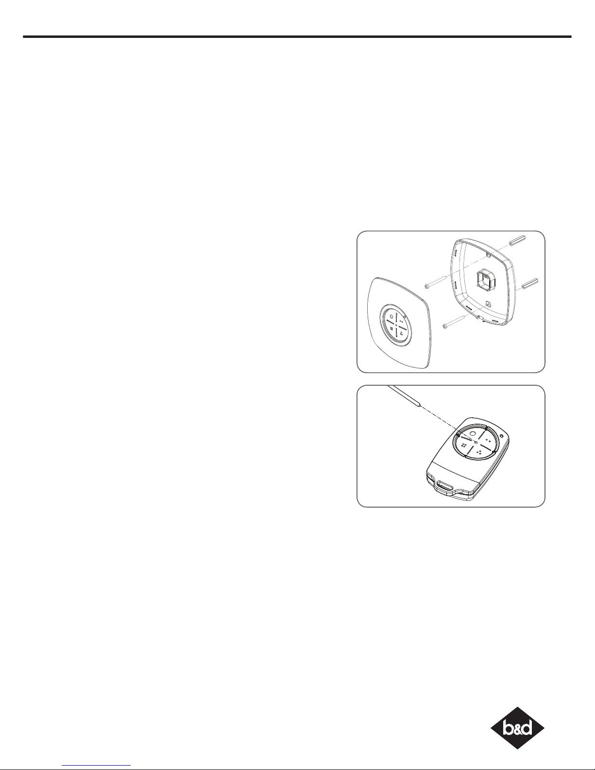
Installation of the Wall Mounted Transmitter (RDO-1V4 Only)
a. Mount the transmitter in a convenient location, yet out of reach of
children and at least 1.5m off the ground.
b. Make sure the door is visible from this location.
c. To set the transmitter press the CODE SET button and release. The CODE
SET LED will illuminate to indicate the opener is in Code Learn mode. If
a valid code is not stored within 15 seconds the opener will exit Code
Learn.
d. Press the transmitter button (one of four) that you want to control the
door. The CODE SET LED will flash.
e. Press the same transmitter button again. The CODE SET LED will illuminate
for one second then go out.
f. The transmitter button is now coded - press to test
Remotely Coding Transmitters
Using this method transmitters can be coded without access to the
opener’s control panel as long as a pre-coded transmitter is available.
a. Take any pre-coded transmitter. Press the button for the function to be
duplicated and release.
b. Using a small needle / pen, press and hold firmly for two seconds the
middle button, through the Coding Hole.
c. Within ten (10) seconds take the additional transmitter you wish to
code. Hold the new transmitter’s button for two seconds, pause for two
seconds, hold again for two seconds and then release.
d. Wait for ten (10) seconds and then press the new transmitter’s button
to test.
Erasing Programmed Codes
If the CODE SET button is pressed and held for six (6) seconds the CODE
SET LED will blink rapidly for one second to indicate that all programmed
codes have been erased.
CAD PD Only
14. Coding a Transmitter
Page 14
Controll-A-Door® Power Drive & Roll-A-Pro® Instruction Manual
14
B&D Doors to the extent that such may be lawfully excluded hereby expressly disclaims all conditions or warranties, statutory or otherwise which may be implied by laws as
conditions or warranties of purchase of a B&D Garage Door Opener. B&D Doors hereby further expressly excludes all or any liability for any injury, damage, cost, expense
or claim whatsoever suffered by any person as a result whether directly or indirectly from failure to install the B&D Garage Door Opener in accordance with the installation
instructions.
Please read these important safety warnings!
This automatic garage door opener is designed and tested to offer safe service provided it is installed
and operated in strict accordance with the following safety warnings. Failure to comply with the
following instructions may result in death, serious personal injury or property damage.
WARNING!
• When operating the manual release while the door is open, the door may fall rapidly due to
weak or broken springs, or due to being improperly balanced.
• DO NOT disengage the opener to manual operation with children/persons or any objects
including motor vehicles within the doorway.
• If the door is closing and does not re-open when obstructed, discontinue use. DO NOT use a
door with faulty obstruction sensing.
ELECTROCUTION!
• Place opener in protected area so that it does not get wet.
• DO NOT spray with water .
• DO NOT open the protective covers.
• DO NOT operate opener if cable is damaged.
DO NOT DO IT
YOURSELF
• Keep the garage door balanced. Sticking or binding doors must be repaired. Garage doors,
door springs, brackets and their hardware are under extreme tension and can cause serious
personal injury. DO NOT attempt any garage door adjustment. DO NOT use if repair or
adjustment is needed. Call for a professional garage door service.
CAUTION:
Emergency access • If your garage has no pedestrian entrance door, an emergency access device should be
installed. This accessory allows manual operation of the garage door from outside in case of
power failure.
Entrapment under
operating door
• Watch the moving door and keep people away until the door is completely opened or
closed. DO NOT operate door when persons are near the door.
• DO NOT allow children to play with door controls or transmitters.
• Regularly conduct Open and Close cycle testing.
• Ensure the garage door is in good working order by undertaking regular servicing.
• Wall transmitters should be installed in a location where the garage door is visible, but out of
the reach of children at a height of at least 1.5m.
• Install Safety Beams (recommended).
Fall from Ladder • Ensure ladder is the correct type for the job.
• Ensure ladder is on flat ground.
• Ensure user has 3 points of contact while on ladder.
Entanglement in or
laceration from
moving door
• Keep hands and loose clothing clear of door and guides at all times.
• Keep hands clear of moving door as sharp edges can cause cuts or lacerations.
DIY
15. Home Owner Safety Warnings!
Page 15
15
Controll-A-Door® Power Drive & Roll-A-Pro® Instruction Manual
16. Opener Safety & Security
Your Door CAN NOT be used by the opener when:
a. There is a locking device installed.
b. There is a power failure.
Your Door CAN be used when:
a. There is an emergency, by disengaging the opener.
b. There is a power failure, by disengaging the opener.
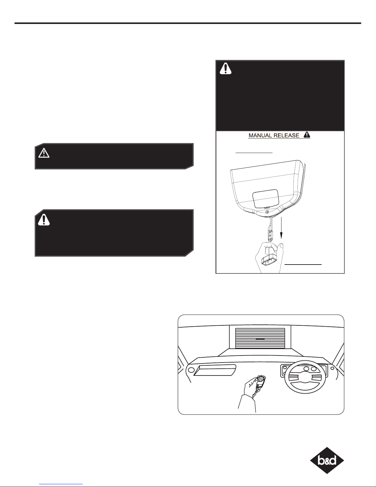
To Disengage the Opener:
a. It is recommended to do so with the door in the closed position.
b. Pull down on the manual release cord, until you hear a click.
c. Move the door manually.
To Re-Engage the Opener:
a. Check the door has not been locked by a locking device.
b. Pull down on the manual release cord, until you hear a click.
c. The door will now operate from the opener.
CAUTION: When the opener is manually disengaged,
the door is no longer locked. To lock the door manually,
re-engage the opener after the door is closed.
WARNING! Please test the manual release mechanism
to ensure that the manual release is easy to operate.
No more than 15 kg of force should be required to
disengage the door using the manual release cord. If
excessive force is required reset the close limit position
(Section 10. Resetting Door Limits).
17. Operating your Opener
To Operate the opener:
a. Press the programmed transmitter button until your
door begins to move (usually 2 seconds). Make sure
you can see the door when you use the transmitter.
b. If you are in a vehicle you should aim the transmitter
through your windscreen as shown.
c. Check that the door is fully open or closed before you
drive in or away.
d. If you press the transmitter whilst the door is moving
the door will stop. The next press of the transmitter will
move the door in the opposite direction.
1.
TO DISENGAGE:
PULL HANDLE DOWN
& RELEASE
2.
TO RE-ENGAGE:
REPEAT ACTION
PULL
HANDLE
WARNING! When operating the manual
release (while the door is open) the door
may fall rapidly due to weak or broken
springs, or due to being improperly
balanced.
Do not disengage the opener to manual
operation with children/persons or any
objects including motor vehicles within the
doorway.
Page 16
Controll-A-Door® Power Drive & Roll-A-Pro® Instruction Manual
16
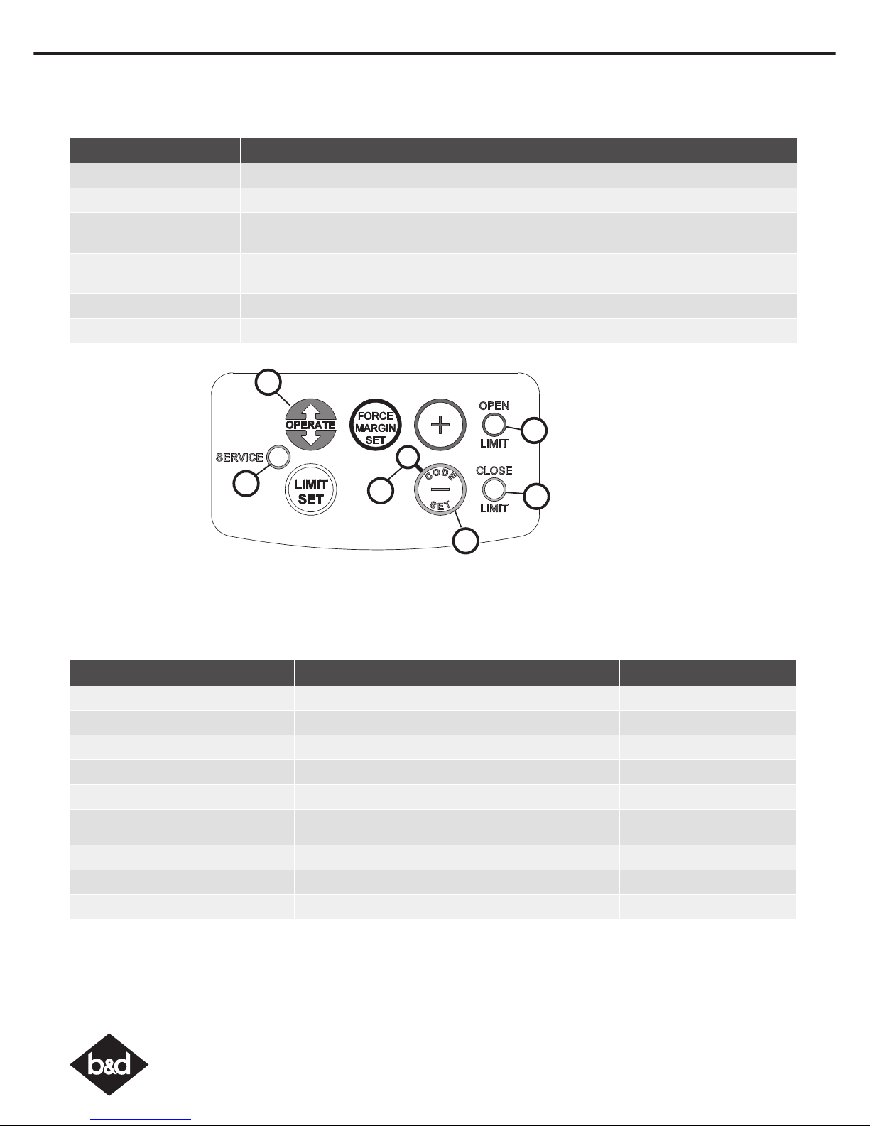
19. Door Status Indicators
Door Status Indicators OPEN LED (green) CLOSE LED (red) Beeper
Open On
Close On
Opening Flashing
Closing Flashing
Door travel stopped Flashing Flashing
Door obstructed when opening Flashing Beeps while door is moving
Door obstructed when closing Flashing Beeps while door is moving
Opener overloaded Alternating flashes Alternating flashes
Mains power interrupted Rapid flashes
Button (Fig 5.1) Function
1. OPERATE Opens/stops/closes the door.
2. CODE SET LED (Red) Flashes when a code is being stored or when the transmitter button is pressed
3. CLOSE LIMIT LED (Red) Illuminates and flashes as the door closes, and remains on when the close limit position has
been reached.
4. OPEN LIMIT LED (Green) Illuminates and flashes as the door opens and remains on when the open limit position has
been reached.
5. SERVICE LED (Yellow) Indicates when the opener requires service or repairs.
6. CODE SET and MINUS (-) Is used for storing or erasing transmitter buttons for door operation
18. User Operating Controls
02
03
04
01
06
05
Page 17
17
Controll-A-Door® Power Drive & Roll-A-Pro® Instruction Manual
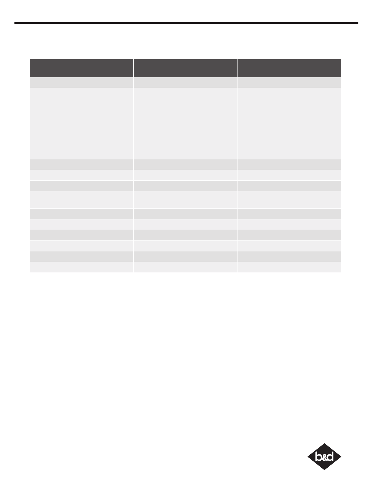
20. Specifications
Technical Specifications Controll-A-Door®
Power Drive
Roll-A-Pro
®
Power supply 230V - 240Va.c. 50Hz 230V - 240Va.c. 50Hz
Maximum door opening
Door Height:
Maximum Door Weight:
Door Area:
Door must be well balanced and
able to be operated by hand, as per
warranty conditions and standard
AS/NZS 4505:2012
3.25 turns of the drum wheel
(approx. 3000mm)
110kg
16.5m
2
3.25 turns of the drum wheel
(approx. 3000mm)
110kg
15.0m
2
Minimum sideroom 41mm 41mm
Lift Force 600N (60kg) 500N (50kg)
Nominal force 150N (15kg) 150N (15kg)
Receiver type Multi-frequency UHF FM
(433.47, 433.92 & 434.37MHz)
Multi-frequency UHF FM
(433.47, 433.92 & 434.37MHz)
Receiver code storage capacity 64 x Tri-Tran+ 4-button Transmitters 8 x Tri-Tran+ 4-button Transmitters
Coding System Tri-Tran+ Technology Tri-Tran+ Technology
Coding type Non-linear encryption algorithm Non-linear encryption algorithm
Number of code combinations Over 100 billion random codes Over 100 billion random codes
Transmitter battery CR2032 (3 Volts) CR2032 (3 Volts)
Courtesy light LED (Light Emitting Diodes) LED (Light Emitting Diodes)
Note: Intermittent operations may occur in areas which experience very strong winds. The strong wind puts extra pressure on the
door and tracks which may in turn intermittently trigger the safety obstruction detection system.
Page 18
Controll-A-Door® Power Drive & Roll-A-Pro® Instruction Manual
18
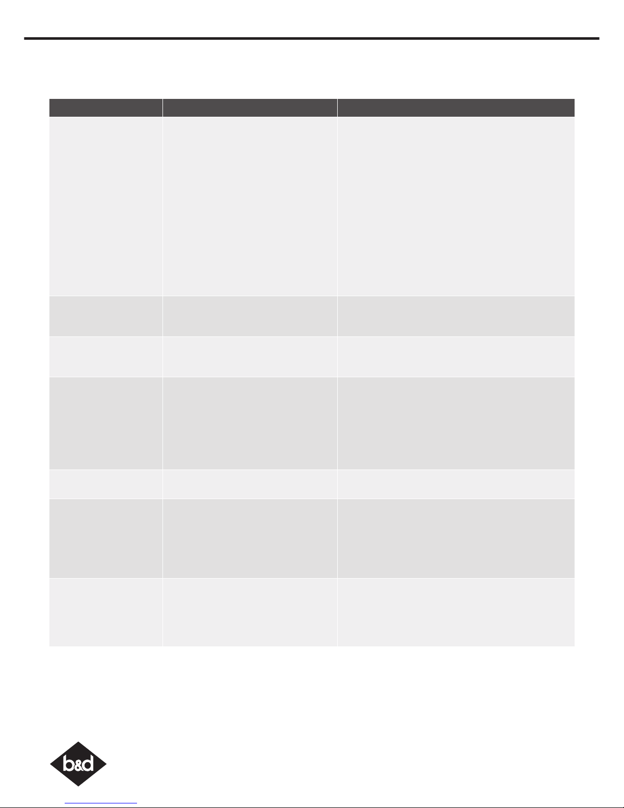
Symptom Possible cause Remedy
The opener does not
work from the transmitter
The opener does not have power
The battery in the transmitter is flat
Transmitter does not contain
Tri-Tran+ Technology
The opener has been put into
“Vacation Mode”
The transmitter button is not
programmed to operate the door.
Door Code LED is flashing yet the
opener is not working.
Plug a device of similar voltage (e.g. a hairdryer) into
the power point and check that it is OK
Replace the battery
Check that the transmitter has grey buttons and the
model number on the back displays V2. Contact
dealer for support if otherwise.
Turn off “Vacation Mode”
(Section 14)
Code in the transmitter
Ensure the correct button on the transmitter is being
pressed.
One transmitter works
but the other/s do not
Faulty transmitter
Flat battery
Replace transmitter
Replace battery
The motor is running
but the door remains
stationary
The opener is disengaged Re-engage the opener
The transmitter range
varies or is restricted
Variations are normal depending on
conditions e.g. temperature or external
interference
The battery life is exhausted
Position of the transmitter in the motor
vehicle
Make sure you can see the door when you use the
transmitter.
Check the battery status by pressing a button
(flashing or no light requires battery to be changed)
Aim the transmitter through the windscreen.
The Courtesy light does
not work
LED has failed Change LED.
The door reverses for no
apparent reason
This may occur occasionally from
environmental conditions such as
areas that are windy, dusty or have
extreme temperature changes.
If Safety beams are installed they may
be partially obstructed.
Ensure the door runs smoothly before increasing the
force pressure.
Ensure the beam path is not obstructed. Check the
Alignment.
The door stops or moves
very slowly.
Garage door in poor condition e.g.
springs may be broken.
(Optional Battery Back Up Accessory)
The batteries may have little OR no
charge
Check the door’s operation.
Connect mains power and leave the batteries to
charge. The batteries may take 24 to 48 hours to
reach their maximum charge capacity.
21. Troubleshooting
Page 19
19
Controll-A-Door® Power Drive & Roll-A-Pro® Instruction Manual
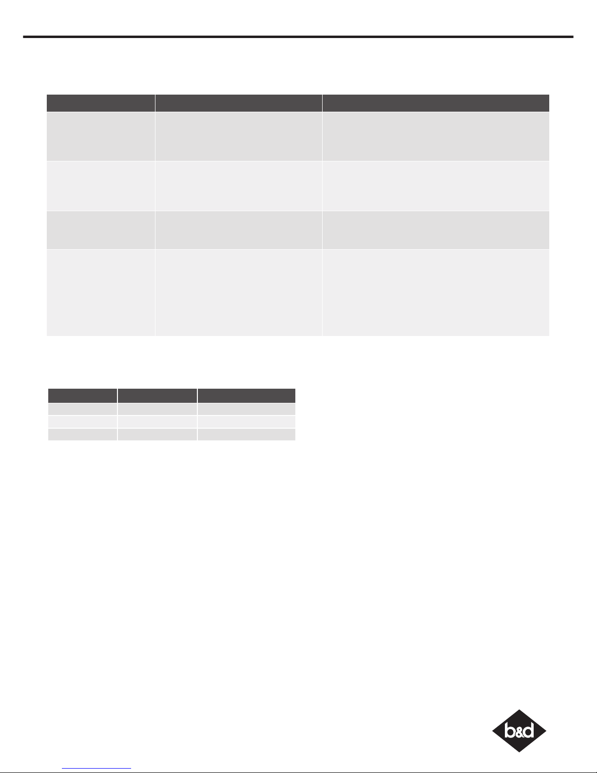
Symptom Possible cause Remedy
The SERVICE LED has
started to flash and
is beeping numerous
times
A Fault has been detected. The fault
will be active each time an attempt is
made to operate the door.
Record opener function (How many beeps?) then
press the LIMIT SET button once to reset the opener. If
the fault continues to be tripped contact 1300 300
625 for support.
The Open (Green) LED
and Close (Red) LED are
flashing alternatively
Opener is overloaded Check the doors operation by disengaging the motor
and ensuring the door runs smoothly. If necessary
make door adjustments or discontinue use and
contact 1300 300 625 for support.
The Open (Green) LED
continues to flash
Door obstructed when opening Clear away any obstructions and test door opens
correctly. (If door is damaged, contact your door
professionl).
The Close (Red) LED
continues to flash
Door obstructed when closing
Limits may be cleared
Clear away any obstructions and test door closes
correctly. (If door is damaged, contact your door
professional).
Remove all power sources (including the battery
backup). Wait till all lights are out (10-15 secs), then
reconnect power. If Red LED is flashing, limits are not
set. Reset Limits.
21 Troubleshooting
If You Need a Service Call
If the opener needs a service please call the dealer who installed the garage door opener (their contact details are
usually on a sticker on the back of your garage door). For product assistance contact 13 62 63 within Australia.
BEFORE CALLING you should have the following information to assist in providing the appropriate service:
1. Has anything happened since the opener last operated OK, e.g. a storm, a jolt to the door etc.?
2. What is the current light status on the opener?
3. Manually disengage the door (Section 16).
How easy is it to manually open and close the door?
4. What model is the opener? (Model no. information is located at the rear of the opener)
5. Who installed the opener? (Dealer details should be on a sticker on the back of your garage door)
6. When was it installed? (If known)
Date Time Number of Beeps
Page 20
Controll-A-Door® Power Drive & Roll-A-Pro® Instruction Manual
20
22. Maintenance
Door Maintenance
A poorly maintained door could cause fatal / serious injuries or
damage to property.
• Frequently examine the door, particularly the cables, springs and
mountings for signs of wear, damage or imbalance. DO NOT USE
if repair or adjustment is needed since a fault in the installation or
an incorrectly balanced door may cause injury.
• Fasterners: Check all screws, nuts and bolts to ensure they are
secure.
• Spring Tension: It is natural for springs to lose tension. Should the
door become hard to operate or completely inoperative, contact
a door professional.
• Guide Tracks: Clean the internal sections of the guide tracks every
3 - 6 months with a cloth dampened with mineral turps or methylated
spirits.
DO NOT DO IT YOURSELF:
WARNING! Failure to maintain your garage
door may void the warranty on your garage
door opener.
DIY
Door adjustments should only be
carried out by experienced persons,
as this function can be dangerous if not
performed under strict safety procedures.
When batteries reach the end of their usual life in accordance with Australian Battery Recycling Initiative please follow the next
simple steps for protecting the environment. Refer to the Automatic Technology website for information on where to recycle
batteries in Australia.
DO NOT throw the batteries in municipal waste. This symbol of the crossed out wheeled bin indicates that
the battery should not be placed in the municipal waste. Check your local regulations for appropriate
disposal of the batteries.
Recycling all batteries will have other environmental and social benefits:
WARNING! Prior to disposal, recycling, or collection, all battery terminals must be securely
insulated with a non conductive material to prevent any two batteries from short circuiting
and generating heat during storage or transport. Battery terminals may be insulated with
electrical tape; or batteries may be individually packaged in a non conductive material
(e.g., plastic bag or original packaging).
24. Battery Disposal
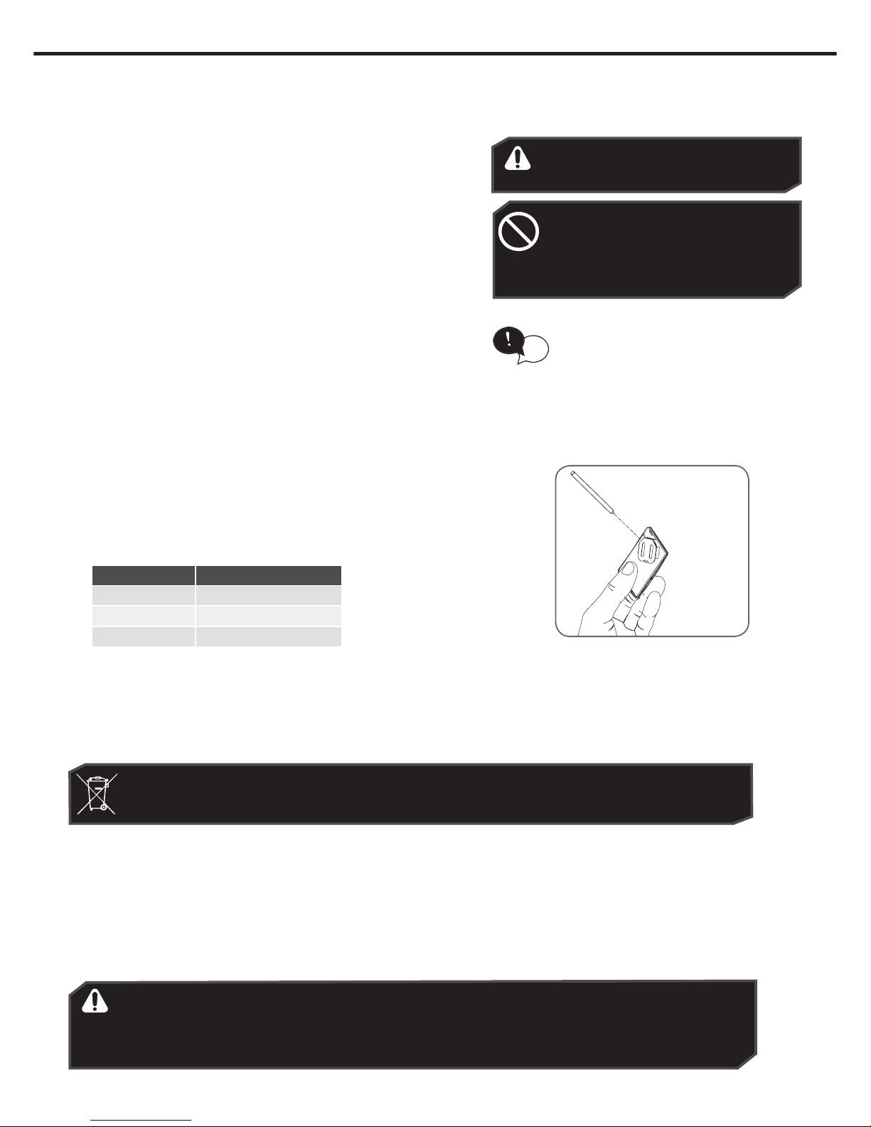
Battery Type:
3V Lithium Battery CR2032.
• To test the battery is working, press and
hold a transmitter button. Check Light
Status table to determine if battery needs
replacing
Light Status Battery Status
Solid OK
Flashing Requires replacement
No light Requires replacement
23. Battery Replacement
Use a pen
to push the
battery down
through the
side opening
to release
battery
Run the Safety Testing procedures
MONTHLY in Section 11 to ensure garage
door is fit for use.
tip
• Use finger nails to separate
the transmitter casing to
expose circuit board.
• Use a non-metallic object
(e.g. pen) to remove the
battery.
• Some batteries are less toxic but hazardous for other
reasons. Lithium batteries can explode or catch fire in
landfill, while button cells are dangerous if swallowed by
children. Recycling offers a safe and environmentally
responsible solution for end of life batteries.
• Battery recycling recovers non-renewable materials such
as lead, cadmium, stella, zinc, manganese, cobalt, silver,
plastics and rare earth elements.
• Removal of batteries and other hazardous household
products from household waste facilitates the recovery of
organic materials through alternative waste technologies
such as composting. Batteries and heavy metals are
known contaminants in compost.
• The community supports recycling because it reduces
waste to landfill and achieves environmental benefits.
Page 21
21
Controll-A-Door® Power Drive & Roll-A-Pro® Instruction Manual
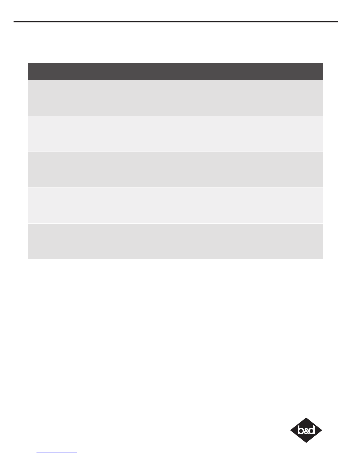
25. Service Schedule
B&D Doors is a division of B&D Australia Pty Ltd
Phone: 13 62 63
Website: www.bnd.com.au
Year /
Approx. Cycles
Date Details
1 / 3,000
2 / 6,000
3 / 9,000
4 / 12,000
5 / 15,000
Page 22

Controll-A-Door® Power Drive & Roll-A-Pro® Instruction Manual
22
Product: Controll-A-Door® Power Drive and Roll-A-Pro
®
Purchased from:______________________________Purchaser:___________________________________
(described as “you” below)
Address:_____________________________________Installed by:__________________________________
Installed on (date):____________________________Invoice No:__________________________________
26. Warranty
1. MAKING A CLAIM -
To make a warranty claim you must:
a. produce a copy of the receipt of purchase, together with this warranty certificate
with the above details completed; and
b. where the Product has been sold by B&D, make all warranty claims directly with
B&D by sending it to B&D at the relevant address set out in paragraph 2 below; or
c. where the Product has been sold by an approved distributor, make all warranty
claims directly with the approved distributor. If you are unsure of the correct
address of the approved distributor from which you purchased the product, you
can send your claim to B&D with the rest of the above details completed, including
the original invoice number, and we will forward it to the distributor.
You are responsible for the expense of making a claim under this warranty.
2. B&D OR APPROVED DISTRIBUTORS ONLY -
This warranty is in addition to any statutory, non-excludable guarantees or warranty
rights under Australian or New Zealand laws (as applicable). This warranty applies only
to Products sold by B&D or its approved distributor. “B&D” means in Australia - B&D
Doors of 34 – 36 Marigold St, Revesby NSW 2212 and in New Zealand - B&D Doors (NZ)
Limited of 30C Allens Road, East Tamaki Auckland. “Approved distributor” means an
approved reseller of B&D products purchasing on open account, from B&D, for the
purpose of supplying those products to end users.
3. WHAT THE WARRANTY COVERS -
B&D warrants, subject to paragraph 4, that it will, at its option, either repair or replace
(in a manner B&D considers reasonable) any proven defects:
a. in installation for a period of one year from the date of installation where the CAD
Power Drive or Roll-A-ProTM (Product) has been installed by B&D or its approved
distributor;
b. in materials, manufacture or workmanship in the Product, as follows:
i. for all components of the Product that make up the power head (including any
track assembly) that is attached to a garage door and that are installed by B&D
or an approved distributor, the warranty will be valid for:
• Controll-A-Door® Power Drive - a period of seven (7) years or 20,000 cycles,
which ever occurs first, provided that the Product is serviced annually by B&D
or its approved distributor;
• Roll-A-Pro® - a period of five (5) years or 10,000 cycles, which ever occurs
first, provided that the Product is serviced annually by B&D or its approved
distributor;
ii. for all components of the Product that make up the power head (including any
track assembly) that is attached to a garage door and that are not installed by
B&D or an approved distributor, the warranty is valid for a period of one year,
provided that all costs of disconnection, reinstallation and return freight are to
be borne by you;
iii. for all other components of the Product the warranty is valid for a period of one
year; and
in each case the warranty applies from the later of the date of purchase, delivery or
installation by B&D or an approved distributor (as applicable).
4. WHAT THE WARRANTY DOES NOT COVER -
This warranty does not cover:
a. batteries or globes - B&D will not be liable for any defect or failure in them;
b. adjustments - (as described in the Instruction Manual provided with the Product)
which are not defects - you will need to pay for any service calls for adjustments;
c. model modifications - B&D will not be required to incorporate modifications made
to existing/future Product models;
d. travel expenses - incurred by B&D or its approved distributor in either travelling to and
from or transporting the Product to/from areas outside a capital city metropolitan
area - you will need to pay for these expenses; or
e. additional access expenses - incurred by B&D or an approved distributor in
obtaining access where the Product is not readily accessible - you will need to pay
for those additional expenses.
5. WHAT VOIDS THE WARRANTY -
Subject to paragraph 6, this warranty does not extend to, and B&D will be relieved of,
all obligations, responsibilities and liabilities in the event that defects in the Product are
directly or indirectly, in the opinion of B&D, due to or resulting from:
a. unreasonable use - the Product not being used correctly in accordance with the
Instruction Manual or other unreasonable use;
b. instructions - failure to observe any instructions or directions (including “warning”
notifications in the Instruction Manual), provided with the Product or given to you;
c. other devices - the Product being fitted to any door or other closing device which
is not of the type or condition defined in the Instruction Manual as suitable for
installation of the Product;
d. installation or adjustment - faulty installation or adjustment of the Product or door to
which the Product is connected where such installation or adjustment is not carried
out by B&D or its approved distributors;
e. unauthorised acts - modifications or repairs made or attempted to be made by
you or any unauthorised person;
f. service - lack of proper maintenance, service or care of the door and Product;
g. outside control - events or acts beyond the reasonable control of B&D;
h. settings - use with doors locked or operation of the Product with excessively high
opening or closing force settings
i. wiring - faulty electrical wiring of structures to which the Product is affixed;
j. interference - radio (including citizen brand transmissions) or other electronic
interference;
k. water damage - including effects from rust and corrosion);
l. salt - salt corrosion or damage to the surface coatings or base materials due to
environmental conditions (such as proximity to the sea-front or similar corrosive
conditions).
m. continuous operating time - maximum continuous operating time exceeding 1
minute in 10;
n. maximum operating force – the operating force exceeding 15kg* (150 Newton)
when moving the door manually to the open or closed position;
o. door size – the door surface area exceeding 15.0m2;
p. modifications - any unauthorised modification to the Product;
q. insects damage - damage caused by insects; or
r. non-residential use – installation of a residential garage door opener in a
commercial or industrial premises or in a dwelling other than a single-family
dwelling.
6. STATUTORY GUARANTEES OR WARRANTIES –
Australia
If you are a consumer under the Australian Consumer Law, our goods come with
guarantees that cannot be excluded under the Australian Consumer Law. You are
entitled to a replacement or refund for a major failure and for compensation for any
other reasonably foreseeable loss or damage. You are also entitled to have the goods
repaired or replaced if the goods fail to be of acceptable quality and the failure does
not amount to a major failure.
This warranty certificate and other statements contained in this document or other B&D
documents given to you do not exclude, restrict or modify the application of all or any
of the provisions of the Australian Consumer Law.
New Zealand
This warranty certificate and other statements contained in this document or other B&D
documents given to you do not exclude, restrict or modify the application of the New
Zealand Consumer Guarantees Act (collectively defined as the “Act’); or the exercise
of rights conferred by other statutory provisions which cannot be excluded, restricted
or modified, provided that to the extent that the Act or other statutory provision permits
B&D to limit its liability for a breach of a statutory guarantee or warranty, B&D’s liability for
such breach is limited to the payment of the cost of replacing the Product or acquiring
an equivalent Product or repairing the Product.
In Australia, this warranty is given by B&D Australia Pty Limited (ABN 25 010 473 971)
of B&D Doors of 34 – 36 Marigold St, Revesby NSW 2212, phone 13 62 63 and email
[email protected]. In New Zealand, this warranty is given by BD Doors (NZ) Limited
of 30C Allens Road, East Tamaki, Auckland, phone 09-273 8600 and email enquiries@
bnd.co.nz
This warranty document is not intended to create a contract between B&D and the
purchaser.
Note:
1. * The door that the Product is used with should be balanced in such a way that the
user is able to open or close the door manually using a force not greater than 150
Newton (15 kg), other than to initially cause the door to start moving, which may
require force in excess of that specified in this paragraph.
Page 23
23
Controll-A-Door® Power Drive & Roll-A-Pro® Instruction Manual
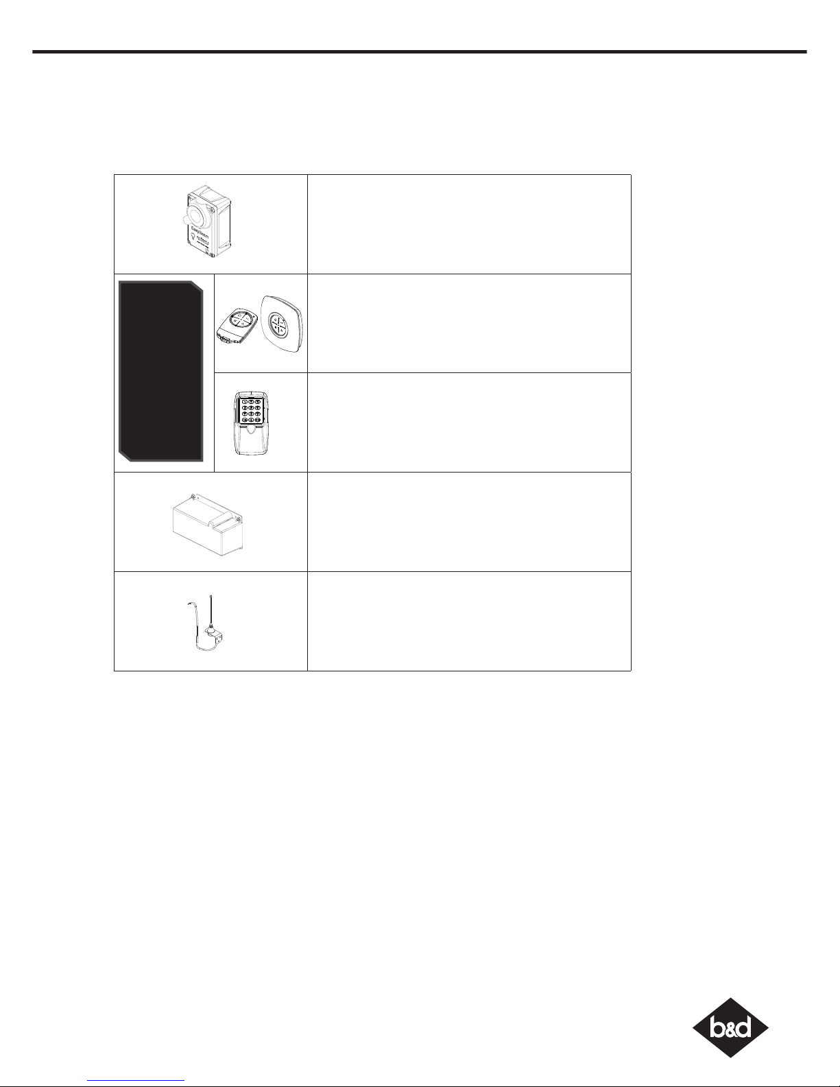
27. Optional Accessories
There are a range of additional accessories for your added convenience and security.
Contact your Dealer for installation of these accessory items.
• Safety Beams - Provides additional protection if the
door is closing onto your property or person. Simply
breaking the beam “stops” the door!
• Keyring Transmitter - Ideal for personal use when
entry into the house may be via the garage.
• Wall Button Transmitter - Allows you to operate
the opener within 10 metres of the door. Ideal for
mounting inside the house.
• Wireless Keypad - The entr y keypad allows entry to
the garage without using a transmitter.
• Battery Back-up - The opener has a provision for a
Battery Back Up kit that allows continued operation of
the door in the absence of mains power.
(Not available with the Roll-A-ProTM)
• External Antenna - For sites where radio range may
be reduced.
IMPORTANT NOTE:
Only Tri-Tran+
TM
Technology
Transmitters and Keypads
are compatible with these
products.
TB-6 Shown
Page 24
Controll-A-Door® Power Drive & Roll-A-Pro® Instruction Manual
20
B&D Doors is a division of B&D Australia Pty Ltd
ABN 25 010 473 971
Is your door sticking and
hard to operate?
It may be time for a service
(for more details see section 22)
For a service, contact your dealer using the details below...
Dealer:
© copyright 2016
 Loading...