

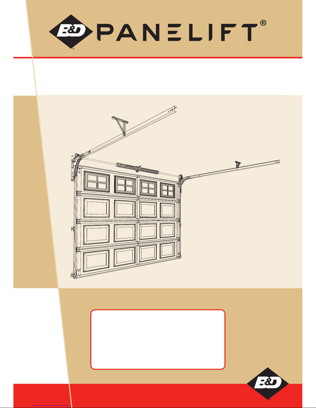
B&D Panelift B&D Storm-Shield PFI, Panelift Icon PFI, Panelift PFT, Panelift Insul-Shield Installation Instructions Manual
Page 1
Part No. OT2515. Revision 9 - March 2016
DISCLAIMER
THESE INSTRUCTIONS ARE INTENDED FOR
PROFESSIONAL GARAGE DOOR INSTALLERS
Note: All references are taken from inside looking out.
Substrate fasteners are not included, the recommended
fasteners and high wind compliant Storm-Shield fasteners can
be downloaded from the installation section on the B&D website
Panelift® PFT, Panelift® Icon™ PFI,
B&D Storm-Shield™ PFI and Insul-Shield™
INSTALLATION INSTRUCTIONS
Page 2

CONTENTS
1.0 BEFORE YOU START 3
1.1 SAFETY CHECKLIST 3
1.2 CHECKING MEASUREMENTS 4
1.3 FASTENER RECOMMENDATIONS FOR FITTING PANELIFT
®
PFT & PFI DOORS ONLY 5
1.4 TOOLS 6
1.5 PARTS CHECKLIST 7
1.6 CHECK & MARK OUT THE OPENING 10
2.0 INSTALLATION 11
2.1 ASSEMBLING PFT & PFI VERTICAL TRACKS 11
2.2 ASSEMBLING B&D STORM-SHIELD™ PFI VERTICAL TRACKS 12
2.3 ASSEMBLING BOTTOM & MIDDLE PANELS 13
2.4 FITTING PFT & PFI REINFORCING 14
2.5 FITTING REINFORCING & END HOOKS TO BOTTOM & MIDDLE PANEL OF B&D STORM-SHIELD™ PFI 15
2.6 ASSEMBLING TOP PANEL PFT, PFI & PFI SEAL 15
2.7 ASSEMBLING THE TOP PANEL & FITTING REINFORCING TO B&D STORM-SHIELD™ PFI 16
2.8 INSTALLING VERTICAL TRACKS 17
2.9 ADDING PANELS 18
2.10 INSTALLING HORIZONTAL TRACKS 19
2.11 STANDARD SPRING COUNTERBALANCE SYSTEM 21
2.12 FITTING B&D STORM-SHIELD™ PFI TRACKLOCKS 23
2.13 LARGE DOORS - TWO PIECE SHAFTS 25
2.14 REAR TORSION INSTALLATION (PFT & PFI ONLY) 26
2.15 ADDING TENSION TO SPRING 28
3.0 OPTIONAL COMPONENTS 29
3.1 LOCK INSTALLATION (PFT & PFI ONLY) 29
3.2 HINGED TAPERS 30
4.0 TROUBLESHOOTING 31
5.0 AFTER INSTALLATION CARE 32
2
Panelift® PFT, Panelift® Icon™ PFI, B&D Storm-Shield™ PFI and Insul-Shield™ Installation Instructions
Revision 9 - March 2016
NOTE: PRODUCT ABBREVIATIONS USED IN THESE INSTRUCTIONS ARE
PANELIFT® PFT, PANELIFT® ICON PFI AND B&D STORM-SHIELD™ PFI.
Page 3
1.0 BEFORE YOU START
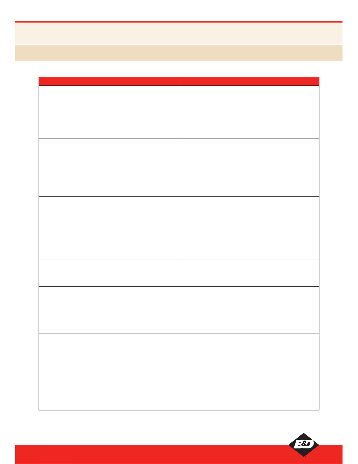
The following hazards and hazard controls have been identified for installers during the installation of this door.
1.1 SAFETY CHECKLIST
Hazard Control
• Housekeeping - risk of slip trip or fall
• Housekeeping - risk of injury to other people or animals
in the installers work area
• Tidy up site prior to start work as a minimum area should
be at least the area of the installation back into the garage
and 2 metres in front
• If the Site housekeeping is deemed to be unsafe do not
install the door
• Keep all people well clear of installers work area with
appropriate signage and discussion with owner
• Manual handling when moving the door from the Trailer
or Ute to the installation area - risk of musculoskeletal
injury
• Manual handling when installing Doors & Openers
particularly above head height - risk of musculoskeletal
injury or twisting
• Manual handling when installing tracks and torsion bars -
risk of musculoskeletal injury
• Pack sizes
• Use of 2 person lifts
• Use of mechanical aids
• Avoid twisting (Practice correct lifting techniques)
• Correct use of ladders while installing tracks
• Working at heights and working with ladders, scissor lifts,
scaffold - risk of fall from height
• Ladder check
• Ladder placement
• Do not work off the top rung
• Sharp edges on door, tracks or related jewellery -
risk of laceration
• Wear appropriate PPE (Dyneema cut off Gloves)
• Follow instruction explicitly particularly for the installation
of windows in some panel doors as the unrolled cut out
edges presents a very sharp edge
• Pinch points - risk of cut, puncture or crush injury
• Wear appropriate PPE and keep hands well clear of pinch
points
• Ensure hands well clear of the panels
• Use of hand tools - risk of eye injury, laceration, cut,
stab or puncture injuries (Tools checklist)
• Use of Electric/ Battery or pneumatic tools - noise hazard
• Use of cutting tools creating sparks - risk of fire
• Wear appropriate PPE and utilise operators manual
• Use appropriate noise/hearing protection in the form of
ear plugs or ear muffs
• Ensure appropriate fire protection available and
housekeeping to ensure that flammable liquids or
materials are removed from the area of work
• Tension spring - risk of release of stored energy (striking
installer on the head or body)
• Ensure correctly fitting winding bar is used
• Ensure the correct length winding bar is utilised
• Ensure winding bar is placed appropriately in the torsion
socket plug
• Ensure correct bolts are tightened or loosened (or clamp
pliers) to ensure there is no release or controlled release
of energy from the spring either through the torsion bar or
the winding bar
• Keep hands clear of the torsion plug at all times
• Keep head clear of the tensioning bar at all times
3
Panelift® PFT, Panelift® Icon™ PFI, B&D Storm-Shield™ PFI and Insul-Shield™ Installation Instructions
Revision 9 - March 2016
Page 4
1.2 CHECKING MEASUREMENTS
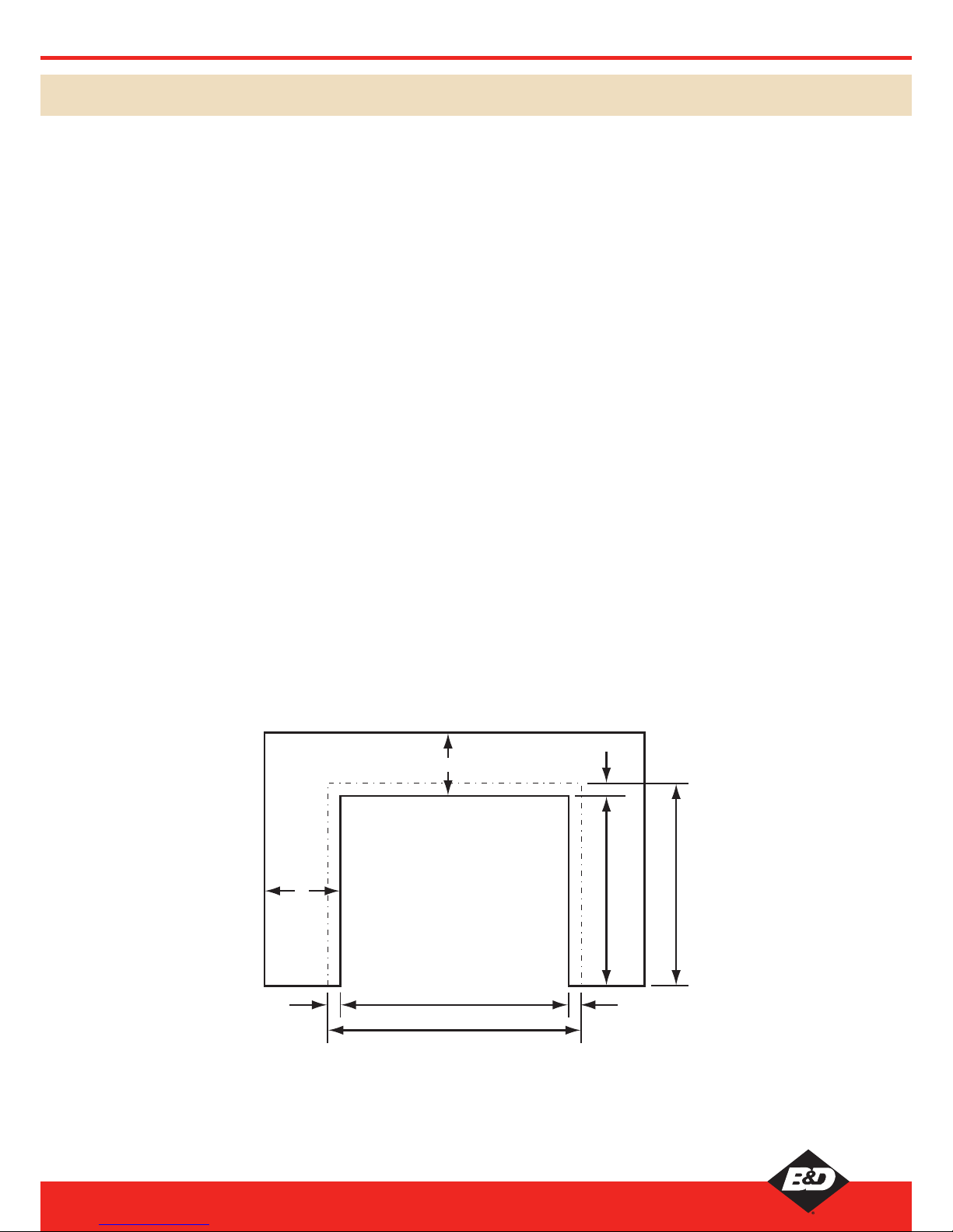
Headroom (standard) 4-8 & 4-13 cable drums (with and without B&D auto opener)
FTL = Front Torsion Large curve 290mm with STD End Bearing brackets 310mm with Combo Brackets
FTS = Front Torsion Small curve 250mm with STD End Bearing brackets 270mm with Combo Brackets
RTS = Rear Torsion Small curve* 190mm without opener 250mm with opener
Headroom (standard) 5-18 cable drums (with and without B&D auto opener)
FTL = Front Torsion Large curve 330mm with STD End Bearing brackets
FTS = Front Torsion Small curve 290mm with STD End Bearing brackets
RTS = Rear Torsion Small curve* 190mm without opener
Side room (with std door overlap)
STD single wheels and axles 120mm
Smooth track double wheels and axles* 130mm - 140mm
Side room rear torsion*
4-8 & 4-13 cable drums 155mm
5-18 cable drums 195mm
Backroom (std headroom door only)
Recommended panel height plus 350mm
Minimum panel height plus 100mm
Minimum with opener panel height plus 600mm
Backroom RTS (RTS rear torsion headroom door only)*
Minimum panel height plus 350mm
Minimum with opener panel height plus 950mm
* RTS is NOT available for B&D Storm-Shield
™
PFI.
Headroom
Sideroom
Opening Height
Door Height
Opening Width
Door Width
30mm
30mm
15mm
4
Panelift® PFT, Panelift® Icon™ PFI, B&D Storm-Shield™ PFI and Insul-Shield™ Installation Instructions
Revision 9 - March 2016
Page 5
5
Panelift® PFT, Panelift® Icon™ PFI, B&D Storm-Shield™ PFI and Insul-Shield™ Installation Instructions
Revision 9 - March 2016
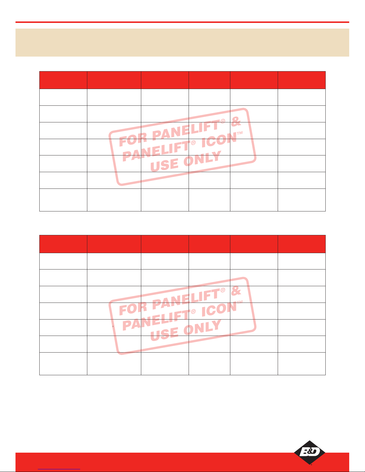
1.3 FASTENER RECOMMENDATIONS FOR FITTING
PANELIFT® PFT & PFI DOORS ONLY
UNLINED GARAGE
SUBSTRATE
TYPE
FASTENER
REQUIRED
WASHER
REQUIRED
PLUG
REQUIRED
DRILLED
HOLE Ø (mm)
MIN HOLE
DEPTH (mm)
Solid Brick
(>10 MPa)
Screw, Coach
5/16-9TPIx50
Washer Flat M8
Plug, Nylon
5/16x50
10 60
Three Hole Brick
(> 30 MPa)
Screw Anka M8x75
Flange Hex Head
Washer 3/8” N/A 8 75
Ten Hole Brick
(>15 MPa)
Screw Anka M8x75
Flange Hex Head
Washer 3/8” N/A 8 75
Concrete Block
(> 8 MPa)
Screw Anka M8x75
Flange Hex Head
Washer 3/8” N/A 8 75
Concrete
(> 15MPa)
Screw, Coach
5/16-9TPIx50
Washer Flat M8
Plug, Nylon
5/16x50
10 60
Timber
Screw, Coach
5/16-9TPIx50
Washer Flat M8 N/A 5 60
Steel Section
(0.9-2mm thick)
Screw Tek
14G-20TPIx25
Flange Hex Head ZP
Washer Flat M8 N/A N/A N/A
LINED GARAGE (UP TO 13MM THICK PLASTERBOARD)
SUBSTRATE
TYPE
FASTENER
REQUIRED
WASHER
REQUIRED
PLUG
REQUIRED
DRILLED
HOLE Ø (mm)
MIN HOLE
DEPTH (mm)
Solid Brick
(>10 MPa)
Screw, Coach
5/16-9TPIx80
Washer Flat M8
Plug, Nylon
5/16x80
10 90
Three Hole Brick
(> 30 MPa)
Screw Anka M8x75
Flange Hex Head
Washer 3/8” N/A 8 75
Ten Hole Brick
(>15 MPa)
Screw Anka M8x75
Flange Hex Head
Washer 3/8” N/A 8 75
Concrete Block
(> 8 MPa)
Screw Anka M8x75
Flange Hex Head
Washer 3/8” N/A 8 75
Concrete
(> 15MPa)
Screw, Coach
5/16-9TPIx80
Washer Flat M8
Plug, Nylon
5/16x80
10 90
Timber
Screw, Coach
5/16-9TPIx50
Washer Flat M8 N/A 5 90
Steel Section
(0.9-2mm thick)
Screw Tek
14G-20TPIx25
Flange Hex Head ZP
Washer Flat M8 N/A N/A N/A
MANDATORY FASTENER REQUIREMENTS FOR B&D STORM-SHIELD™ PFI DOORS
Please ensure you are complying to the latest details. To download the latest DTCM drawings visit their product page on our
website www.bnd.com.au where you will be directed to the DTCM website.
The NT Deemed To Comply Manual (DTCM) is referenced in the Building Code of Australia.
FOR PANELIFT
®
&
PANELIFT
®
ICON
™
USE ONLY
FOR PANELIFT
®
&
PANELIFT
®
ICON
™
USE ONLY
Page 6
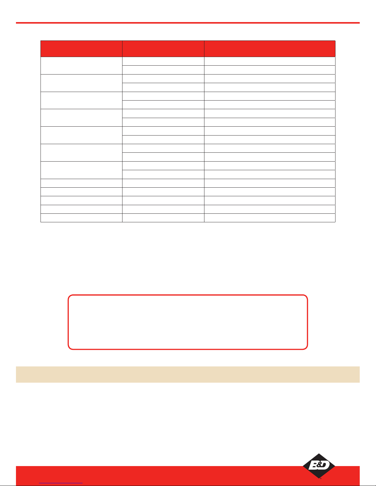
It is recommended that this door is installed by a professorial door installer using a professional and specialized tool kit.
1.4 TOOLS
AVAILABLE B&D STANDARD FASTENER PACKS
FASTENER
STANDARD FASTENER
PACK PART NO.
STANDARD FASTENER PACK DESCRIPTION
Screw, Coach 5/16-9TPIx50
FK0011 Kit, Screw, Coach 5/16-9TPIX50 100pk
FK0012 Kit, Screw, Coach 5/16-9TPIX50 500pk
Screw, Coach 5/16-9TPIx80
FK0013 Kit, Screw, Coach 5/16-9TPIx80 100pk
FK0014 Kit, Screw, Coach 5/16-9TPIx80 500pk
Plug, Nylon 5/16x50
FK0015 Kit, Plug, Nylon 5/16x50 100pk
FK0016 Kit, Plug, Nylon 5/16x50 500pk
Plug, Nylon 5/16x80
FK0017 Kit, Plug, Nylon 5/16x80 100pk
FK0018 Kit, Plug, Nylon 5/16x80 500pk
Screw Tek 14G-20TPIx25
Flange Hex Head ZP
FK0019 Kit, Screw Tek 14-20x25 100pk
FK0020 Kit, Screw Tek 14-20x25 500pk
Screw Tek 14G-20TPIx35
Flange Hex Head ZP
FK0021 Kit, Screw Tek 14-20x35 100pk
FK0022 Kit, Screw Tek 14-20x35 500pk
Screw Masonary M8x75
Flange Hex Head
FK0023 Kit, Screw Anka M8x75 Flange Hex Head 50pk
FK0024 Kit, Screw Anka M8x75 Flange Hex Head 100pk
Screw, Coach M10x90 FK0037 Kit, Screw Coach M10x90 100pk
Plug Nylon 14x70 M10 FK0038 Kit, Plug Nylon 14x70 M10 100pk
Screw Masonary M10x75 FK0028 Kit, Screw Masonary M10x75 100pk
Bolt & Nut 1/4"1/2"UNC FK0040 Kit, Bolt & Nut 1/4x1/2 UNC 100pk
Bolt & Nut 5/16"7/8"UNC FK0041 Kit, Bolt & Nut 5/16x7/8 UNC 100pk
6
Panelift® PFT, Panelift® Icon™ PFI, B&D Storm-Shield™ PFI and Insul-Shield™ Installation Instructions
Revision 9 - March 2016
IMPORTANT INFORMATION ON FASTENERS
The installer must select and use fasteners appropriate to the material into which they are being fixed.
For B&D Storm-Shield
™
PFI doors ensure you are complying to the latest high wind compliant details.
To download the latest drawings visit the B&D website at www.bnd.com.au
IMPORTANT NOTES:
1. For B&D Storm-Shield™ PFI doors ensure you are complying to the latest compliance details.
2. For installation to substrate materials not covered in the above chart, the installer should seek expert advice.
3. The above fasteners are specifically selected for B&D Panelift PFT & PFI doors only.
4. Substitute fasteners are not recommend unless approved.
5. The above chart specifies the fasteners for new substrate materials only. Seek specialist advice regarding pre-existing substrate materials.
6. It is important that correct washer and plug is used and the correct pilot hole drilled where specified.
Page 7
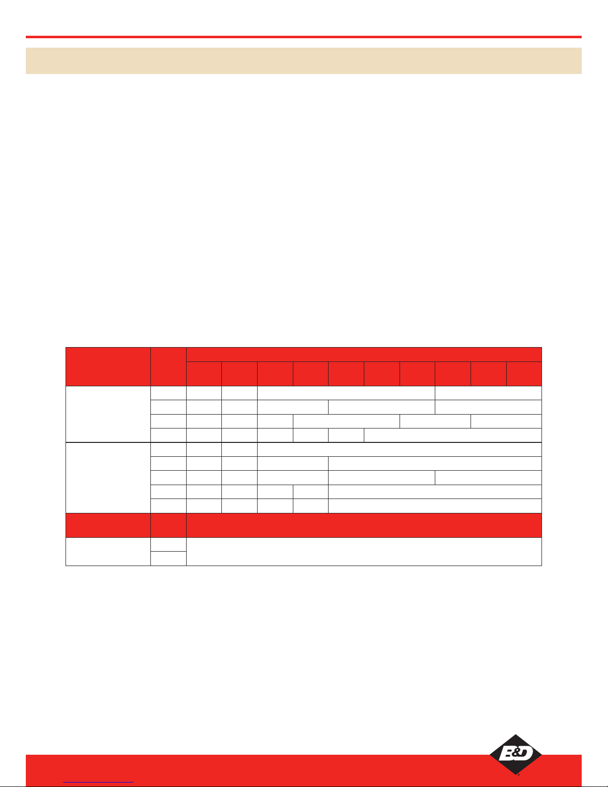
When taking delivery of your PFT or PFI sectional overhead door you will be supplied with the following:-
• 1 package with door panels
• 2 pairs of tracks short for vertical use, and long for horizontal use
• 1 torsion bar (tube or solid)
• For parts boxes refer to PFT or PFI charts as there may be more than one box depending on the model and options
• 1 to 4 springs
• Panel Reinforcing (refer to charts below)
When taking delivery of your B&D Storm-Shield
™
PFI sectional overhead door you will be supplied with:-
• 1 package with door panels
• 2 pairs of tracks short for vertical use, and long for horizontal use
• 1 pair of Tracklocks
• 1 torsion bar (tube or solid)
• 1 pair of jamb spacers
• For parts boxes refer to PFT and B&D Storm-Shield
™
PFI charts as there will be more than one box depending on the
model and options
• 1 to 4 springs
• Panel Reinforcing (refer to chart below)
1.5 PARTS CHECKLIST
REO ASSIGNMENT ALL DOORS
PANEL
COUNT
WIDTH RANGES (from - to, mm)
1800 -
3500
3505 -
4500
4505 -
5000
5005 -
5400
5405 -
5600
5605 -
5800
5805 -
6000
6005 -
6200
6205 -
6400
6405 -
6600
Panelift
®
PFT
3 0 1 2 3
4 0 1 2 3 4
5 0 1 2 3 4 5
6 0 1 2 3 5 6
Panelift
®
Icon
PFI
3 0 2 3
4 0 2 3 4
5 0 2 4 4 5
6 0 2 3 4 6
7 0 2 3 4 7
PANEL
COUNT
1800 - 5500
B&D Storm-Shield
™
PFI
4
1 REO to all panels except the top which has 2
5
If number of reo does not match panel number: 1 Reo = Top Panel
2 Reo = Top Panel + Bottom Panel
3 Reo = Top Panel + Bottom Panel + Middle Panel
7
Panelift® PFT, Panelift® Icon™ PFI, B&D Storm-Shield™ PFI and Insul-Shield™ Installation Instructions
Revision 9 - March 2016
Page 8
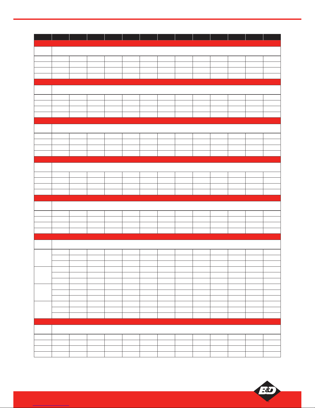
B&D PANELIFT® PFT DOORS AND B&D STORM-SHIELD™ (PFT boxes have GREEN print)
1750 3050 3055 3500 3505 4500 4505 4705 4710 5000 5005 5400 5405 5600 5605 5740 5745 5800 5805 6000 6005 6200 6205 6400 6405 6600
ALL PFT AND STORM-SHIELD™ DOORS - Main Hardware Single Box Kits, Front Torsion, Large Radius Curve (FTL) 290HR
NUMBER
OF PANELS
DOOR WIDTH BREAK POINTS (mm)
3
BOXPF-A1TC1 BOXPF-A1TC1 BOXPFA2TC1 BOXPFA2TC1 BOXPFA2TC1 BOXPFA2TC1
4
BOXPF-A1TC1 BOXPF-A2TC1 BOXPFA2TC1 BOXPFA2TC1 BOXPFA2TC1 BOXPFA2TC1
5
BOXPF-A4TC4 BOXPF-A4TC4 BOXPF-A4TC4 BOXPF-A4TC4 BOXPF-A5TC4 BOXPF-A5TC4 BOX-A7TC7 BOX-A7TC7 BOX-A7TC7 BOX-A7TC7 BOX-A7TC7 BOX-A7TC7 BOX-A7TC7
6
BOXPF-A4TC4 BOXPF-A5TC4 BOXPF-A5TC4 BOXPF-A5TC4 BOX-A7TC7 BOX-A7TC7 BOX-A7TC7 BOX-A7TC7
ALL PFT AND STORM-SHIELD™ DOORS - Main Hardware Single Box Kits, Front Torsion, Small Radius Curve (FTS) 250HR
NUMBER
OF PANELS
DOOR WIDTH BREAK POINTS (mm)
3
BOXPF-A1TB1 BOXPF-A1TB1 BOXPF-A2TB1 BOXPF-A2TB1 BOXPF-A2TB1 BOXPF-A2TB1
4
BOXPF-A1TB1 BOXPF-A2TB1 BOXPF-A2TB1 BOXPF-A2TB1 BOXPF-A2TB1 BOXPF-A2TB1
5
BOXPF-A4TB4 BOXPF-A4TB4 BOXPF-A4TB4 BOXPF-A4TB4 BOXPF-A5TC4 BOXPF-A5TC4 BOX-A7TB7 BOX-A7TB7 BOX-A7TB7 BOX-A7TB7 BOX-A7TB7 BOX-A7TB7 BOX-A7TB7
6
BOXPF-A4TB4 BOXPF-A5TB4 BOXPF-A5TB4 BOXPF-A5TB4 BOX-A7TB7 BOX-A7TB7 BOX-A7TB7 BOX-A7TB7
ALL PFT DOORS - Main Hardware Box (independent of curve size and front or rear torsion)
NUMBER
OF PANELS
DOOR WIDTH BREAK POINTS (mm)
Blank areas are replaced with single box kits
3
BOXPF-A3 BOXPF-A3 BOXPF-A3 BOXPF-A3 BOXPF-A3 BOXPF-A3 BOXPF-A3
4
BOXPF-A3 BOXPF-A3 BOXPF-A3 BOXPF-A3 BOXPF-A3 BOXPF-A3 BOXPF-A3
5
6
BOXPF-A6 BOXPF-A6 BOXPF-A8 BOXPF-A8 BOXPF-A8
PFT DOORS - Front Torsion, Large Radius Curve (FTL) 290HR - Supplementary Parts Box
NUMBER
OF PANELS
DOOR WIDTH BREAK POINTS (mm)
Blank areas are replaced with single box kits
3
BOXPF-TC3 BOXPF-TC3 BOXPF-TC3 BOXPF-TC3 BOXPF-TC3 BOXPF-TC3 BOXPF-TC3
4
BOXPF-TC3 BOXPF-TC3 BOXPF-TC3 BOXPF-TC3 BOXPF-TC3 BOXPF-TC3 BOXPF-TC3
5
6
BOXPF-TC4 BOXPF-TC4 BOXPF-TC7 BOXPF-TC7 BOXPF-TC7
PFT DOORS - Front Torsion, Small Radius Curve (FTS) 250HR (available at extra cost) - Supplementary Parts Box
NUMBER
OF PANELS
DOOR WIDTH BREAK POINTS (mm)
Blank areas are replaced with single box kits
3
BOXPF-TB3 BOXPF-TB3 BOXPF-TB3 BOXPF-TB3 BOXPF-TB3 BOXPF-TB3 BOXPF-TB3
4
BOXPF-TB3 BOXPF-TB3 BOXPF-TB3 BOXPF-TB3 BOXPF-TB3 BOXPF-TB3 BOXPF-TB3
5
6
BOXPF-TB4 BOXPF-TB4 BOXPF-TB7 BOXPF-TB7 BOXPF-TB7
PFT DOORS - Rear Torsion, Small Radius Curve (RTS) 200HR + Standard Bearing Brackets (available at extra cost) - 2 x Supplementary Parts Boxes
NUMBER
OF PANELS
DOOR WIDTH BREAK POINTS (mm)
Blank areas are replaced with single box kits
3
BOXPF-TB3 BOXPF-TB3 BOXPF-TB3 BOXPF-TB3 BOXPF-TB3 BOXPF-TB3 BOXPF-TB3
+ + + + + + + + + + + + +
BOXPF-R1 BOXPF-R1 BOXPF-R1 BOXPF-R1 BOXPF-R1 BOXPF-R1 BOXPF-R1 BOXPF-R1 BOXPF-R1 BOXPF-R1 BOXPF-R1 BOXPF-R1 BOXPF-R1
4
BOXPF-TB3 BOXPF-TB3 BOXPF-TB3 BOXPF-TB3 BOXPF-TB3 BOXPF-TB3 BOXPF-TB3
+ + + + + + + + + + + + +
BOXPF-R1 BOXPF-R1 BOXPF-R1 BOXPF-R1 BOXPF-R1 BOXPF-R1 BOXPF-R1 BOXPF-R1 BOXPF-R1 BOXPF-R1 BOXPF-R1 BOXPF-R1 BOXPF-R1
5
+ + + + + + + + + + + + +
BOXPF-R1 BOXPF-R1 BOXPF-R1 BOXPF-R1 BOXPF-R1 BOXPF-R1 BOXPF-R1 BOXPF-R1 BOXPF-R1 BOXPF-R1 BOXPF-R1 BOXPF-R1 BOXPF-R1
6
BOXPF-TB4 BOXPF-TB4 BOXPF-TB7 BOXPF-TB7 BOXPF-TB7
+ + + + + + + + + + + + +
BOXPF-R1 BOXPF-R1 BOXPF-R1 BOXPF-R1 BOXPF-R1 BOXPF-R1 BOXPF-R1 BOXPF-R1 BOXPF-R1 BOXPF-R1 BOXPF-R2 BOXPF-R2 BOXPF-R2
ALL PFT DOORS - Supplementary Insul-Shield™ Box
NUMBER
OF PANELS
DOOR WIDTH BREAK POINTS (mm)
3
BOXPF-F1 BOXPF-F1 BOXPF-F2 BOXPF-F2 BOXPF-F2 BOXPF-F2 BOXPF-F3 BOXPF-F3 BOXPF-F3 BOXPF-F3 BOXPF-F3 BOXPF-F3 BOXPF-F3
4
BOXPF-F1 BOXPF-F2 BOXPF-F2 BOXPF-F2 BOXPF-F2 BOXPF-F2 BOXPF-F3 BOXPF-F3 BOXPF-F3 BOXPF-F3 BOXPF-F3 BOXPF-F3 BOXPF-F3
5
BOXPF-F4 BOXPF-F4 BOXPF-F4 BOXPF-F4 BOXPF-F5 BOXPF-F5 BOXPF-F7 BOXPF-F7 BOXPF-F7 BOXPF-F7 BOXPF-F7 BOXPF-F7 BOXPF-F7
6
BOXPF-F4 BOXPF-F5 BOXPF-F5 BOXPF-F5 BOXPF-F6 BOXPF-F6 BOXPF-F7 BOXPF-F7 BOXPF-F7 BOXPF-F7 BOXPF-F8 BOXPF-F8 BOXPF-F8
B&D STORM-SHIELD™ PFI ADDITIONAL PARTS
•SD0040partsboxfor4paneldoor •SD0041L/HandSD0042R/HTracklockkit
•SD0039partsboxfor5paneldoor •SD0041L/HandSD0042R/HTracklockkit
8
Panelift® PFT, Panelift® Icon™ PFI, B&D Storm-Shield™ PFI and Insul-Shield™ Installation Instructions
Revision 9 - March 2016
Page 9
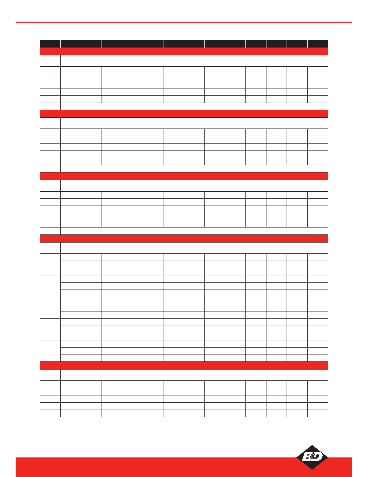
B&D PANELIFT® ICON PFI DOORS (PFI boxes have RED print)
1750 3050 3055 3500 3505 4500 4505 4705 4710 5000 5005 5400 5405 5600 5605 5740 5745 5800 5805 6000 6005 6200 6205 6400 6405 6600
ALL PFI DOORS - Main Hardware Box (independent of curve size and front or rear torsion)
NUMBER
OF PANELS
DOOR WIDTH BREAK POINTS (mm)
3
BOXPF-A1 BOXPF-A1 BOXPF-A2 BOXPF-A2 BOXPF-A2 BOXPF-A3 BOXPF-A3 BOXPF-A3 BOXPF-A3 BOXPF-A3 BOXPF-A3 BOXPF-A3 BOXPF-A3
4
BOXPF-A1 BOXPF-A2 BOXPF-A2 BOXPF-A2 BOXPF-A2 BOXPF-A3 BOXPF-A3 BOXPF-A3 BOXPF-A3 BOXPF-A3 BOXPF-A3 BOXPF-A3 BOXPF-A3
5
BOXPF-A4 BOXPF-A4 BOXPF-A4 BOXPF-A4 BOXPF-A5 BOXPF-A7 BOXPF-A7 BOXPF-A7 BOXPF-A7 BOXPF-A7 BOXPF-A7 BOXPF-A7 BOXPF-A7
6
BOXPF-A4 BOXPF-A5 BOXPF-A5 BOXPF-A5 BOXPF-A6 BOXPF-A7 BOXPF-A7 BOXPF-A7 BOXPF-A7 BOXPF-A7 BOXPF-A8 BOXPF-A8 BOXPF-A8
7
BOXPF-A4 BOXPF-A5 BOXPF-A5 BOXPF-A5 BOXPF-A6 BOXPF-A8 BOXPF-A8 BOXPF-A8 BOXPF-A8 BOXPF-A8 BOXPF-A8 BOXPF-A8 BOXPF-A8
All If Combo Brackets set to NO, add BOXPF-D2
PFI DOORS - Front Torsion, Large Radius Curve (FTL) + Combos 310HR - Supplementary Parts Box
NUMBER
OF PANELS
DOOR WIDTH BREAK POINTS (mm)
3
BOXPF-IC1 BOXPF-IC1 BOXPF-IC1 BOXPF-IC1 BOXPF-IC1 BOXPF-IC1 BOXPF-IC1 BOXPF-IC1 BOXPF-IC1 BOXPF-IC1 BOXPF-IC1 BOXPF-IC1 BOXPF-IC1
4
BOXPF-IC1 BOXPF-IC1 BOXPF-IC1 BOXPF-IC1 BOXPF-IC1 BOXPF-IC1 BOXPF-IC1 BOXPF-IC1 BOXPF-IC1 BOXPF-IC1 BOXPF-IC1 BOXPF-IC1 BOXPF-IC1
5
BOXPF-IC4 BOXPF-IC4 BOXPF-IC4 BOXPF-IC4 BOXPF-IC4 BOXPF-IC7 BOXPF-IC7 BOXPF-IC7 BOXPF-IC7 BOXPF-IC7 BOXPF-IC7 BOXPF-IC7 BOXPF-IC7
6
BOXPF-IC4 BOXPF-IC4 BOXPF-IC4 BOXPF-IC4 BOXPF-IC4 BOXPF-IC7 BOXPF-IC7 BOXPF-IC7 BOXPF-IC7 BOXPF-IC7 BOXPF-IC8 BOXPF-IC8 BOXPF-IC8
7
BOXPF-IC4 BOXPF-IC4 BOXPF-IC4 BOXPF-IC4 BOXPF-IC4 BOXPF-IC8 BOXPF-IC8 BOXPF-IC8 BOXPF-IC8 BOXPF-IC8 BOXPF-IC8 BOXPF-IC8 BOXPF-IC8
All If Combo Brackets set to NO, add BOXPF-D2
PFI DOORS - Front Torsion, Small Radius Curve (FTS) + Combos 270HR - Supplementary Parts Box
NUMBER
OF PANELS
DOOR WIDTH BREAK POINTS (mm)
3
BOXPF-IB1 BOXPF-IB1 BOXPF-IB1 BOXPF-IB1 BOXPF-IB1 BOXPF-IB1 BOXPF-IB1 BOXPF-IB1 BOXPF-IB1 BOXPF-IB1 BOXPF-IB1 BOXPF-IB1 BOXPF-IB1
4
BOXPF-IB1 BOXPF-IB1 BOXPF-IB1 BOXPF-IB1 BOXPF-IB1 BOXPF-IB1 BOXPF-IB1 BOXPF-IB1 BOXPF-IB1 BOXPF-IB1 BOXPF-IB1 BOXPF-IB1 BOXPF-IB1
5
BOXPF-IB4 BOXPF-IB4 BOXPF-IB4 BOXPF-IB4 BOXPF-IB4 BOXPF-IB7 BOXPF-IB7 BOXPF-IB7 BOXPF-IB7 BOXPF-IB7 BOXPF-IB7 BOXPF-IB7 BOXPF-IB7
6
BOXPF-IB4 BOXPF-IB4 BOXPF-IB4 BOXPF-IB4 BOXPF-IB4 BOXPF-IB7 BOXPF-IB7 BOXPF-IB7 BOXPF-IB7 BOXPF-IB7 BOXPF-IB8 BOXPF-IB8 BOXPF-IB8
7
BOXPF-IB4 BOXPF-IB4 BOXPF-IB4 BOXPF-IB4 BOXPF-IB4 BOXPF-IB8 BOXPF-IB8 BOXPF-IB8 BOXPF-IB8 BOXPF-IB8 BOXPF-IB8 BOXPF-IB8 BOXPF-IB8
All If Combo Brackets set to NO, add BOXPF-D2
PFI DOORS - Rear Torsion, Small Radius Curve (RTS) 200HR + Standard Bearing Brackets (available at extra cost) - 2 x Supplementary Parts Boxes
NUMBER
OF PANELS
DOOR WIDTH BREAK POINTS (mm)
3
BOXPF-IB1 BOXPF-IB1 BOXPF-IB1 BOXPF-IB1 BOXPF-IB1 BOXPF-IB1 BOXPF-IB1 BOXPF-IB1 BOXPF-IB1 BOXPF-IB1 BOXPF-IB1 BOXPF-IB1 BOXPF-IB1
+ + + + + + + + + + + + +
BOXPF-R1 BOXPF-R1 BOXPF-R1 BOXPF-R1 BOXPF-R1 BOXPF-R1 BOXPF-R1 BOXPF-R1 BOXPF-R1 BOXPF-R1 BOXPF-R1 BOXPF-R1 BOXPF-R1
4
BOXPF-IB1 BOXPF-IB1 BOXPF-IB1 BOXPF-IB1 BOXPF-IB1 BOXPF-IB1 BOXPF-IB1 BOXPF-IB1 BOXPF-IB1 BOXPF-IB1 BOXPF-IB1 BOXPF-IB1 BOXPF-IB1
+ + + + + + + + + + + + +
BOXPF-R1 BOXPF-R1 BOXPF-R1 BOXPF-R1 BOXPF-R1 BOXPF-R1 BOXPF-R1 BOXPF-R1 BOXPF-R1 BOXPF-R1 BOXPF-R1 BOXPF-R1 BOXPF-R1
5
BOXPF-IB4 BOXPF-IB4 BOXPF-IB4 BOXPF-IB4 BOXPF-IB4 BOXPF-IB7 BOXPF-IB7 BOXPF-IB7 BOXPF-IB7 BOXPF-IB7 BOXPF-IB7 BOXPF-IB7 BOXPF-IB7
+ + + + + + + + + + + + +
BOXPF-R1 BOXPF-R1 BOXPF-R1 BOXPF-R1 BOXPF-R1 BOXPF-R1 BOXPF-R1 BOXPF-R1 BOXPF-R1 BOXPF-R1 BOXPF-R1 BOXPF-R1 BOXPF-R1
6
BOXPF-IB4 BOXPF-IB4 BOXPF-IB4 BOXPF-IB4 BOXPF-IB4 BOXPF-IB7 BOXPF-IB7 BOXPF-IB7 BOXPF-IB7 BOXPF-IB7 BOXPF-IB8 BOXPF-IB8 BOXPF-IB8
+ + + + + + + + +
+ + + +
BOXPF-R1 BOXPF-R1 BOXPF-R1 BOXPF-R1 BOXPF-R1 BOXPF-R1 BOXPF-R1 BOXPF-R1 BOXPF-R1 BOXPF-R1 BOXPF-R2 BOXPF-R2 BOXPF-R2
7
BOXPF-IB4 BOXPF-IB4 BOXPF-IB4 BOXPF-IB4 BOXPF-IB4 BOXPF-IB8 BOXPF-IB8 BOXPF-IB8 BOXPF-IB8 BOXPF-IB8 BOXPF-IB8 BOXPF-IB8 BOXPF-IB8
+ + + + + + + + + + + + +
BOXPF-R1 BOXPF-R1 BOXPF-R1 BOXPF-R1 BOXPF-R1 BOXPF-R2 BOXPF-R2 BOXPF-R2 BOXPF-R2 BOXPF-R2 BOXPF-R2 BOXPF-R2 BOXPF-R2
ALL PFI DOORS - Supplementary Insul-Shield™ Box
NUMBER
OF PANELS
DOOR WIDTH BREAK POINTS (mm)
3
BOXPF-F1 BOXPF-F1 BOXPF-F2 BOXPF-F2 BOXPF-F2 BOXPF-F3 BOXPF-F3 BOXPF-F3 BOXPF-F3 BOXPF-F3 BOXPF-F3 BOXPF-F3 BOXPF-F3
4
BOXPF-F1 BOXPF-F2 BOXPF-F2 BOXPF-F2 BOXPF-F2 BOXPF-F3 BOXPF-F3 BOXPF-F3 BOXPF-F3 BOXPF-F3 BOXPF-F3 BOXPF-F3 BOXPF-F3
5
BOXPF-F4 BOXPF-F4 BOXPF-F4 BOXPF-F4 BOXPF-F5 BOXPF-F7 BOXPF-F7 BOXPF-F7 BOXPF-F7 BOXPF-F7 BOXPF-F7 BOXPF-F7 BOXPF-F7
6
BOXPF-F4 BOXPF-F5 BOXPF-F5 BOXPF-F5 BOXPF-F6 BOXPF-F7 BOXPF-F7 BOXPF-F7 BOXPF-F7 BOXPF-F7 BOXPF-F8 BOXPF-F8 BOXPF-F8
7
BOXPF-F4 BOXPF-F5 BOXPF-F5 BOXPF-F5 BOXPF-F6 BOXPF-F8 BOXPF-F8 BOXPF-F8 BOXPF-F8 BOXPF-F8 BOXPF-F8 BOXPF-F8 BOXPF-F8
9
Panelift® PFT, Panelift® Icon™ PFI, B&D Storm-Shield™ PFI and Insul-Shield™ Installation Instructions
Revision 9 - March 2016
Page 10
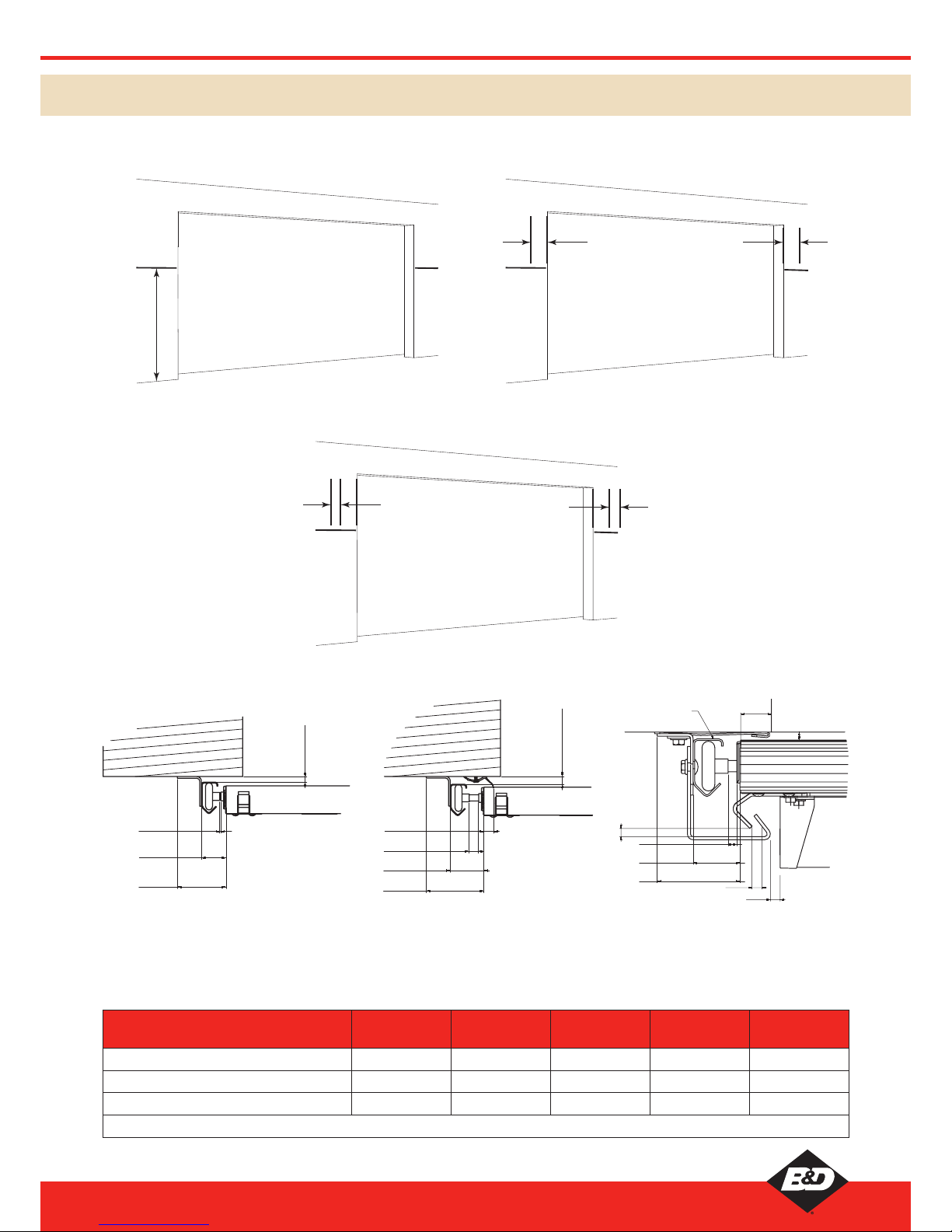
1.6 CHECK & MARK OUT THE OPENING
1. Using a water or lazer level, mark both sides approx. 1.5m
from the floor.
2. Mark equal overlap at each side based on panel width.
Approx.
1.5m
Mark level datum
marks each side
Mark equal overlap
based on panel width
3. Mark the track position as specified in Figure 1.6.2
from the previously marked panel width.
DETAIL
A at bottom
axle
B C D E/F (ref pg 11)
Panelift
®
PFT (Single wheel)
5mm 95mm 60mm n/a 10/5mm
Panelift® Icon™ PFI (Double wheel)
20mm 105mm 70mm 15mm 20/20mm
B&D Storm-Shield
™
PFI (Single wheel)
5mm 95mm 60mm n/a 17/12mm
NOTE: These measurements allow for final adjustment.
FIGURE 1.6.2
FIGURE 1.6.1 WHEEL-AXLE
A
B
C
E/F
D
A
C
B
E/F
A
B
C
E/F
PFT PFI FINAL B&D STORM-SHIELD™ PFI
WITH TRACKLOCK POSITIONING
10
10
30
8
TRACK
A
C
B
E/F
10
Panelift® PFT, Panelift® Icon™ PFI, B&D Storm-Shield™ PFI and Insul-Shield™ Installation Instructions
Revision 9 - March 2016
Page 11
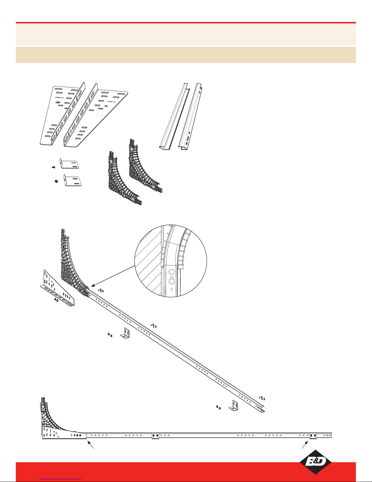
2.0 INSTALLATION
2.1 ASSEMBLING PFT & PFI vERTICAL TRACKS
PARTS NEEDED
FIGURE 2.1.1 TRACK ASSEMBLY
FIGURE 2.1.2 CLEARANCE FROM WALL
Approx measurement from jamb:
No seals E = 10mm, F = 5mm
With seals E&F = 20mm
E F
•1L/h&1R/hverticalstraighttracks
•1L/h&1R/hshorttoptrackangle
•2polypropylenecurves
•4ormoresmallanglejambbrackets
•6x5/16atheadboltswithwiznuts
•4x1/4domedheadboltsandwiznuts
The recomened vertical track cut height should
be door height minus:
Standard large curves less 190mm
Small curves less 170mm
Assemble vertical track bracket, wall brackets
and tracks together as shown in Figure 2.1.1.
Note Figure 2.1.2 when adjusting approximate
track clearance from jamb.
Assemble the rest of the brackets onto the
tracks ensuring the “V” section points away
from the wall bracket.
Before fitting the assembled vertical tracks refer
to the door type and mark out as per Figure
1.6.2 on page 10.
11
Panelift® PFT, Panelift® Icon™ PFI, B&D Storm-Shield™ PFI and Insul-Shield™ Installation Instructions
Revision 9 - March 2016
Page 12
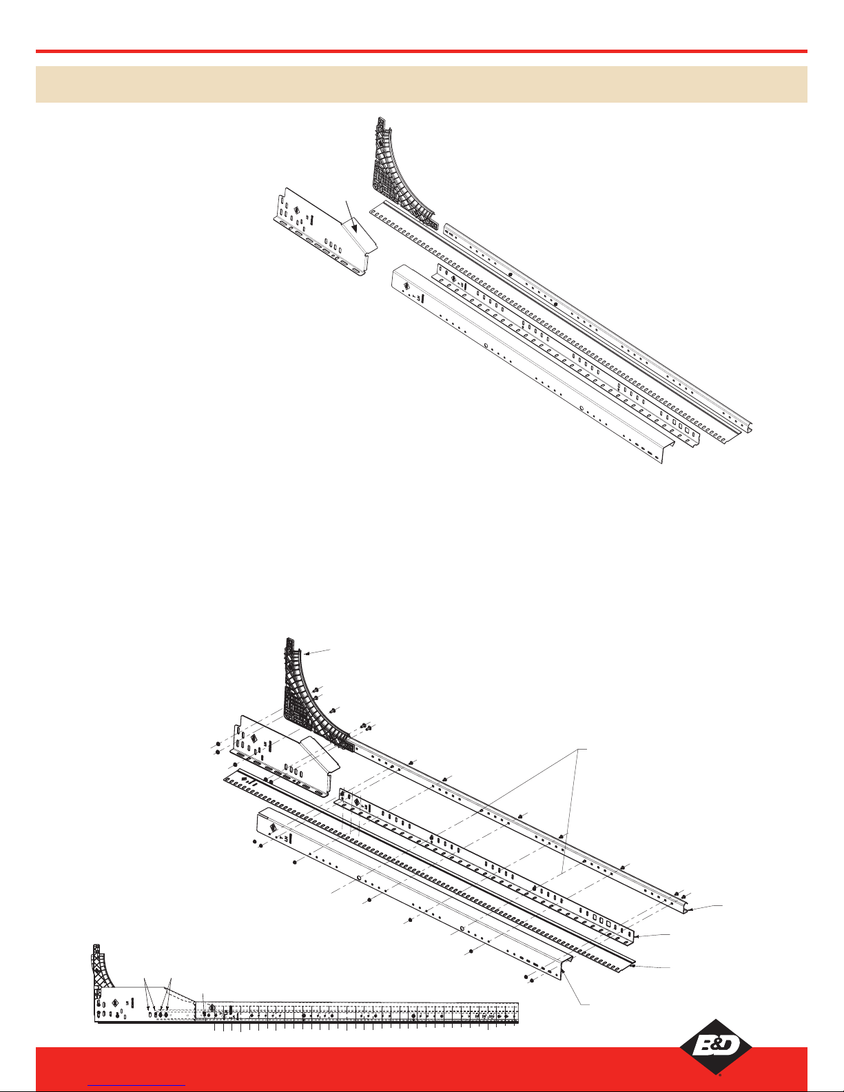
2.2
ASSEMBLING B&D STORM-SHIELD™ PFI vERTICAL TRACKS
First assemble parts A,E and F, loosely attach the
polypropylene curve (F) to the short top track bracket (E)
using 2 long and 3 short 5/16 flat head bolts and nuts for each
assembly as shown.
The small curves will align with the upper slots at the bottom
and large curves with the lower of the four slots, repeat for the
opposite side.
Attach the vertical tracks (A) to (E and F) ensuring the cut end
is at the bottom use 2 x 5/16 flat head bolts and wiz nuts to
each ensuring the ends fit snugly into the polypropylene curves
Now attach the long jamb brackets (B) to each vertical guide,
only attach with 2 x 1/4 dome head bolts and wiz nuts as
shown in the initial alignment holes, these will align with the
larger holes in the tracklock (D) when fitting later.
Refer to measurement E and F (Figure 1.6.2 page 10) before
tighten all nuts and bolts
TIP: To hold the jamb spacer (C) in place prior to fitting the
assembly to the wall fit a 1/4 bolt and wiz nut (dome head
to the wall) to the top this will allow it to hang in place whilst
fastening to the structure.
Before fitting the assembled vertical tracks refer to the door
type and mark out as per Figure 1.6.2 on page 10.
PARTS NEEDED
FIGURE 2.2.1 VERTICAL TRACK ASSEMBLY
The vertical tracks (A) must be cut as a pair,
the cut height should be door height minus:
Large curves less 190mm
Small curves less 170mm
The long jamb fixing brackets (B)
are marked with a ‘T’ indicating top,
do not cut from this end. The jamb spacer (C)
is cut to the full height of the assembled track
with top track bracket fitted make sure they are
cut left and right and from the bottom. Tracklock (D)
are also marked with a “T” indicating the top.
Tracklock cutting and fitting is shown on page 23.
fit warning
label here
Assembled FTL large curve
sample with jamb bracket and
spacer shown in position.
•1L/h&1R/hverticalstraighttracks(A)
•1L/h&1R/hlongjambbrackets(B)
•1L/h&1R/hjambspacer(C)
•1L/h&1R/htracklockbracket(D)
•1L/h&1R/hshorttoptrackanglebrackets(E)
•2polypropylenecurves(F)
•6x5/16atheadboltswithwiznuts
•4x1/4domedheadboltsandwiznuts
• 2xwarninglabels
FIGURE 2.2.1
INITIAL ALIGNMENT
TRACKLOCK-BRACKET
JAMB-SPACER
JAMB-BRACKET
TRACK
NO. OF FASTENERS ON
VERTICAL TRACK:
AVERAGE SHOULD BE
MINIMUM 5 SETS/METRE
3 X SHORT 5/16 BOLTS
2 X LONG 5/16 BOLTS
FTS (SMALL CURVE)
(FTS) (FTL)
This section will be cut when FTS small curves are used refer to Tracklock page 23
E
F
D
B
C
A
12
Panelift® PFT, Panelift® Icon™ PFI, B&D Storm-Shield™ PFI and Insul-Shield™ Installation Instructions
Revision 9 - March 2016
Page 13
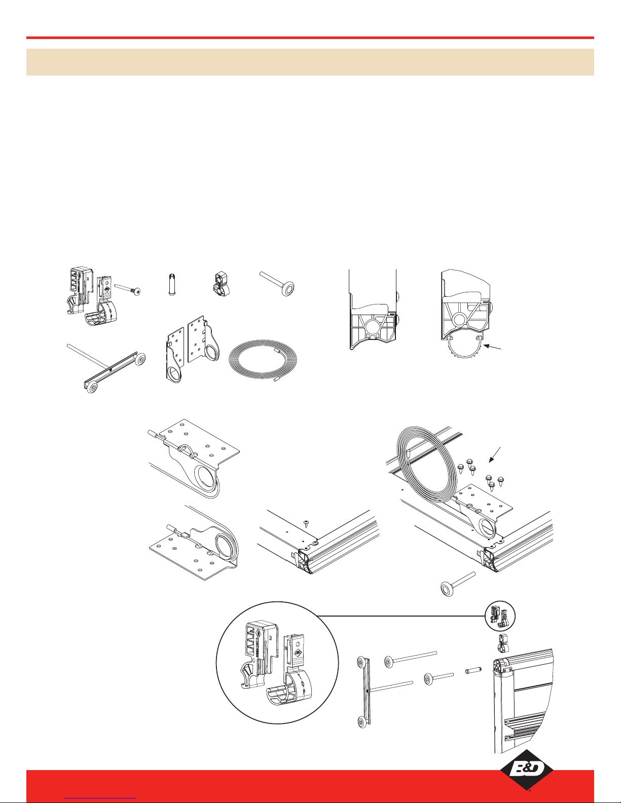
If installing taper please consult page 30. Open up the pack of
door panels making sure the bottom panel (weather strip seal
on the bottom of the panel and Bottom Hinge Hole see Figure
2.3.1) is on top of the pack.
Bottom Panel: Locate both bottom hangers and cables. Insert
cable through the holes of the bottom hanger as shown in
Figure 2.3.2A. Remove existing screws in the two bottom
corners of the panel near the weather strip and discard, see
Figure 2.3.2B. Attach the bottom hangers to the lower end of
the door using 6 TEK screws in each as shown in Figure 2.3.2C.
Insert the polyethylene hinge links into the recesses of the top
of the panel and fix into place using the white pins. Insert four
wheels and axles into the top of the panel (white pins) and the
bottom of the panel (grey block). Insert appropriate wheels
and axles, Figure 2.3.2C & 2.3.3. Ensure the axles are lightly
lubricated with lithium grease before inserting.
Insulated Insul-Shield
™
: Hinge links are in two pieces and clip
together when inserted. After the next panel has been lowered
in place a special screw is inserted to hold in place as shown
in Figure 2.3.3.
Middle Panels: Repeat the process for fitting links, pins and
wheels and axles to the top of each middle panel.
FIGURE 2.3.2
Secure hanger
using 6 TEK
screws to each
A B C
PARTS USED FIGURE 2.3.1
Hinge Pin Hinge Links
Bottom Hangers
(left hand- right hand)
2 Lifting Cable
(variable)
Standard
Bottom
Black Hinge
Other
Panels
Wheel Axles
Smooth-Track™
Insul-Shield™
2.3 ASSEMBLING BOTTOM & MIDDLE PANELS
FIGURE 2.3.3
FITTING THE INSULATED DOOR
SPLIT LINK FROM INSIDE
1. Click the male section of the link
marked TOP in first. Ensure TOP
is facing you from inside looking
out.
2. Insert the female part to the male
and click together.
3. The screw is fitted after the next
panel has been placed onto the
link via the hole provided.
Bottom Grey Hinge
with Offset
Bottom
Panels
Weather
strip
13
Panelift® PFT, Panelift® Icon™ PFI, B&D Storm-Shield™ PFI and Insul-Shield™ Installation Instructions
Revision 9 - March 2016
Page 14
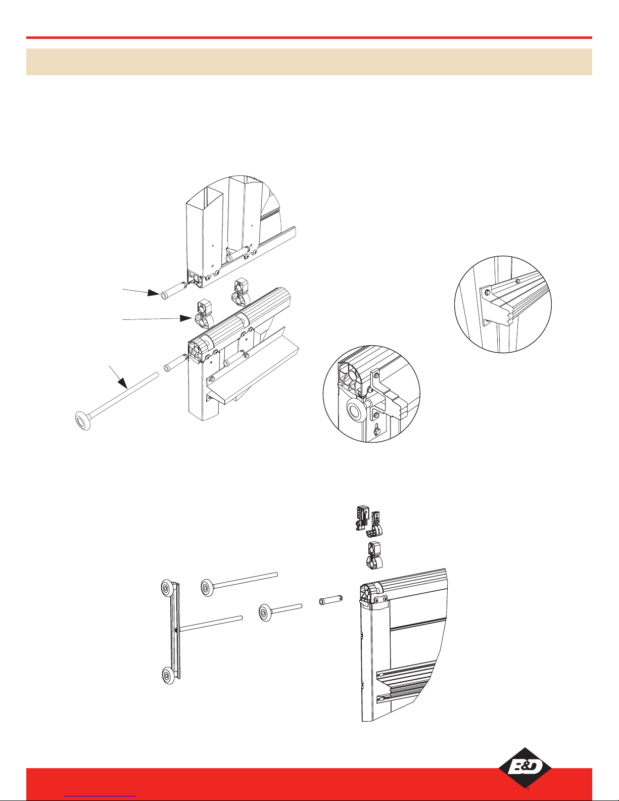
2.4 FITTING PFT & PFI REINFORCING
Doors wider than 3545mm require panel reinforcing, the
number and positioning of the reinforcing is shown on page 7.
Some PFT & PFI doors and all B&D Storm-Shield
™
PFI doors
are supplied with double end stiles and extended wheels,
Figure 2.4.1.
FIGURE 2.4.1
DOUBLE ENDSTILE
DOOR
REINFORCEMENT PLACEMENT
The reinforcement is generally fixed across the centre of
the panel. However there are three situations that require
alternative placement. The top panel with automatic opener,
the top panel with windows, the locking panel when a lock is to
be installed.
If a lock is to be fitted it generally straddles the centre of the
panel so the reinforcement has to be offset to allow clearance
for the installation and operation of the lock.
Fit the top panel reinforcing as high as possible when windows
and automatic openers are fitted (refer detail below).
It is important to secure reinforcing with 2 screws per stile.
FIGURE 2.4.2
REINFORCING WITH
SAFETY END CAPS FITTED
Hinge Pin
Hinge Link
Extended Wheel Axle
FIGURE 2.4.3
REINFORCING INSTALLED
ON THE TOP PANEL OF
THE DOOR
FIGURE 2.4.4 ASSEMBLE LINKS
& PINS ONTO THE PANEL
Insert the polyethylene hinge links into the recesses at the
top of the panel and fix into place using the white pins, insert
appropriate wheels and axles, Figure 2.4.4.
14
Panelift® PFT, Panelift® Icon™ PFI, B&D Storm-Shield™ PFI and Insul-Shield™ Installation Instructions
Revision 9 - March 2016
Page 15
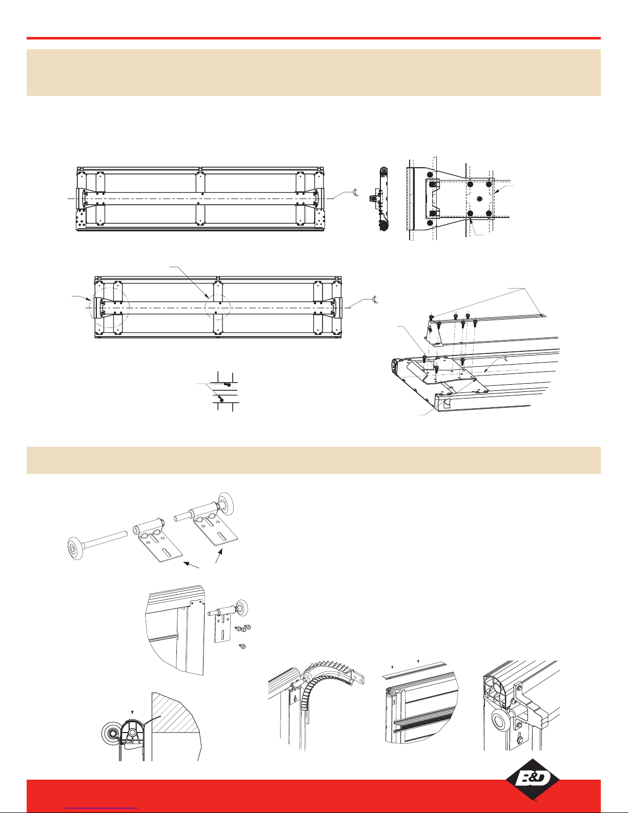
VIEW F:
FASTEN SCREWS
IN DIAGONAL
LOCATION
FIGURE 2.5.3
MID-PANEL
1. LINE UP THE FOLD TO
THE 2ND ENDSTILE
2. FASTEN 3
LOCATING SCREWS
3. LINE UP REO EVENLY
ACROSS PANEL AND
FASTEN ALL SCREWS
2.6 ASSEMBLING TOP PANEL PFT, PFI & PFI SEAL
FIGURE 2.6.4
FIGURE 2.6.6
The top panel can be easily identified by always having a centre stile for use
with an opener and no hinge link cut outs in the curved top edge.
Fit the PFI seal to the top of the top panel as shown in Figure 2.6.4 and Figure
2.6.6 or alternatively fit the seal to the lintel. The fixing points should be spaced
at 300-400mm centres.
First insert the wheels into the top hangers as shown in Figure 2.6.1. Then
assemble top hangers to top corners of the panel as shown in Figure 2.6.2 using
the vertical slots only. The additional two fixings will be fitted to the left and right
side after the panel is lowered into the tracks and adjusted to vertical. The top
panel reinforcing should be fitted as high as possible, refer Figure 2.6.5.
Top Hanger
FIGURE 2.6.3
FIGURE 2.6.2
Ensure all tek
screws indicated
are fitted after
adjusting.
FIGURE 2.6.1
INSTALLING
TOP PANEL
FIGURE 2.6.5
2.5 FITTING REINFORCING & END HOOKS TO BOTTOM
& MIDDLE PANEL OF B&D STORM-SHIELD™ PFI
Reinforcing and hook plates are fitted to the centre of the bottom and middle panels. Take special note of the detail shown and the
position and quantity of the fixings. B&D Storm-Shield
™
PFI reinforcing must be cut 80mm less than the panel width.
FIGURE 2.5.1
NOTCH SHOWS
LOCATION OF HOLES
UNDERNEATH REO
BENT CORNER
ALIGNMENT
MIDDLE PANEL
A
F
BOTTOM PANEL
FIGURE 2.5.2
FIGURE 2.5.4
15
Panelift® PFT, Panelift® Icon™ PFI, B&D Storm-Shield™ PFI and Insul-Shield™ Installation Instructions
Revision 9 - March 2016
Page 16
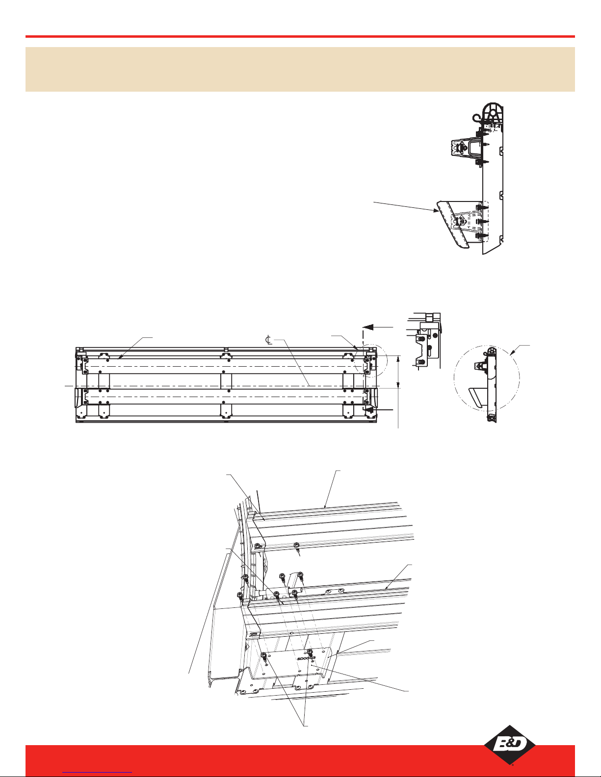
Assembly of the top panel is the same as panelift PFT and PFI.
The reinforcing must be fitted after the panel is in the tracks
in a vertical position with the wheels and hangars fitted and
adjusted.
Special care must be taken when fitting the lower reinforcing
as the hook plates must align correctly with the tracklock of the
short top track bracket Figure 2.7.1 and 2.7.3.
Fit the top reinforcing without hook plates over the top hangar
as shown at section H and previously at Figure 2.4.3.
The second lower reinforcing with hook plates is fixed to align
with the top section of the Tracklock. Refer to section B. This
measurement is taken from the bottom of the folded safety
edge note there is a different measurement for FTL (front
torsion large curve) and FTS (front torsion small curve).
NOTE: Last step - line up reo on top panel with the Tracklock
bracket.
FIGURE 2.7.1
FIGURE 2.7.3
K
K
B
REFER TO NOTE
TOP PANEL
VIEW H:
REO
H
G
SECTION K-K
FIGURE 2.7.2
2.7 ASSEMBLING THE TOP PANEL & FITTING
REINFORCING TO B&D STORM-SHIELD™ PFI
Lower reinforcing and hook
plates must align correctly
with the tracklock
TOP REO
REO (ON HOOK PLATE)
TOP PANEL HOOK PLATE
1. LOCATE HOOK PLATE TO POSITION
(REFER TO SIDE VIEW INSERT)
2. FASTEN 2 LOCATING SCREWS
3. LINE UP REO EVENTLY ACCROSS PANEL AND
FASTEN ALL 6 TEK SCREWS
4. LINE UP TOP REO AND
FASTEN ALL SCREWS
16
Panelift® PFT, Panelift® Icon™ PFI, B&D Storm-Shield™ PFI and Insul-Shield™ Installation Instructions
Revision 9 - March 2016
Page 17
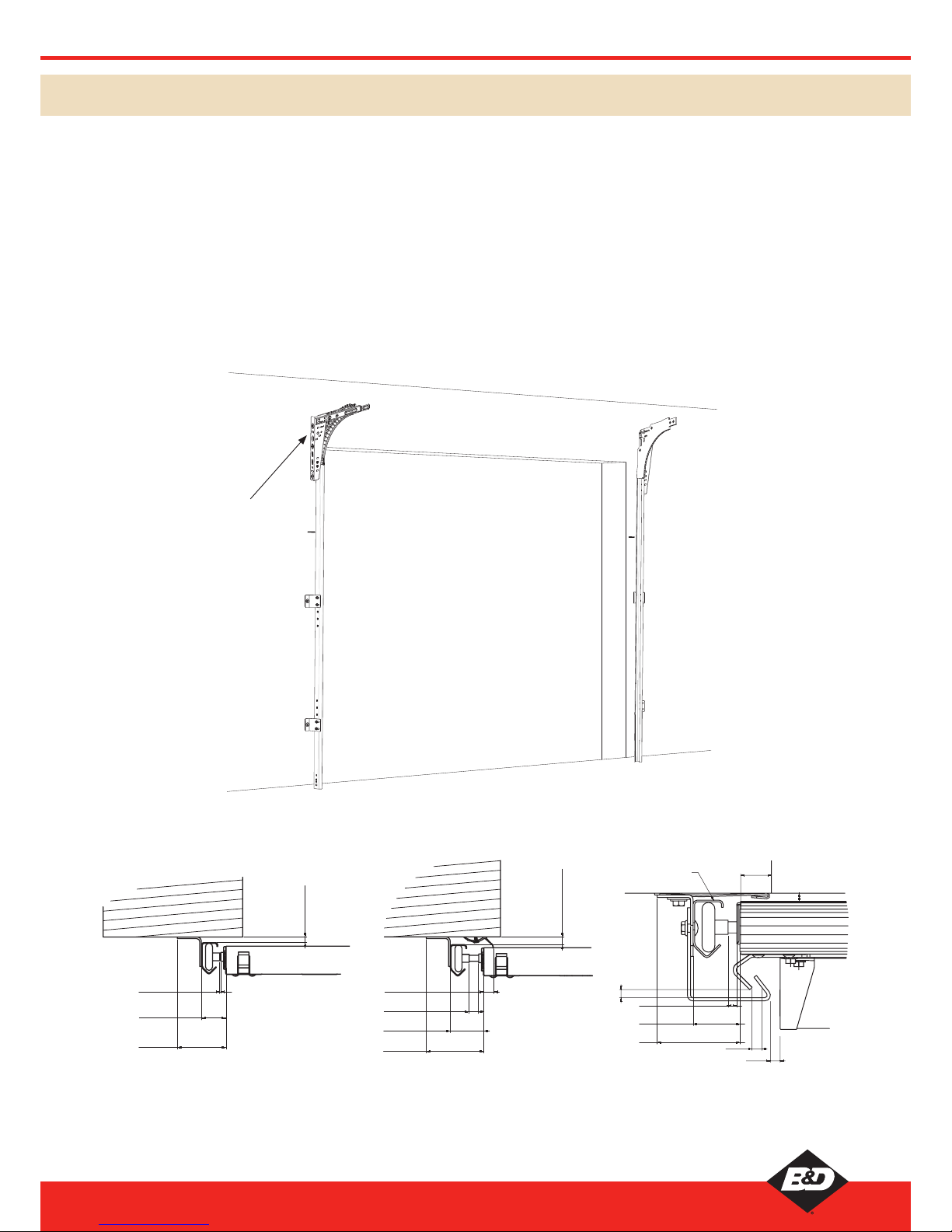
NOTE: If jamb seals are being fitted they should be cut 100mm taller than the door height and fitted prior to fitting the vertical tracks.
Refer to Figure 2.8.2 for correct position. The fixing points should be spaced at 300-400mm centres.
Set the vertical tracks parallel on both sides of the door. Use the level/datum marks to ensure the tracks are level with each other or
the door will not function correctly. Ensure the detail at Figure 2.8.2 is followed. The set out measurements for B&D Storm-Shield
™
PFI are the same as PFT but take note of the positioning for the jamb spacer as they must be fitted under the jamb bracket with the
rolled edge facing you, as indicated at Figure 2.8.2. Once satisfied temporarily fix in position with at least two fixings to the top bracket
and one to the bottom track bracket, these will hold the tracks in position and allow for minor adjustment. All fixings with washers will
be fitted after the door is fully adjusted and operating satisfactorily. (For B&D Storm-Shield
™
PFI doors refer to the DTCM compliance
instructions). Ensure the B&D Storm-Shield
™
pinch point warning stickers are fitted correctly as previously indicated.
FIGURE 2.8.2 WHEEL-AXLE
A
B
C
E/F
D
A
C
B
E/F
A
B
C
E/F
PFT & B&D STORM-SHIELD™ PFI PFI
FIGURE 2.8.1 INSTALLING VERTICAL TRACKS
NOTE: The DTCM compliance fixing
details for B&D Storm-Shield
™
PFI
vertical tracks must be followed
however the initial set out is the same.
NOTE: There must
be at least 3 fixings
with washers to each
top bracket and other
fixings are to have
washers fitted.
Tracks shown are
indicative only.
FINAL B&D STORM-SHIELD
™
PFI
WITH TRACKLOCK POSITIONING
10
10
30
8
TRACK
A
C
B
E/F
2.8 INSTALLING vERTICAL TRACKS
17
Panelift® PFT, Panelift® Icon™ PFI, B&D Storm-Shield™ PFI and Insul-Shield™ Installation Instructions
Revision 9 - March 2016
Page 18
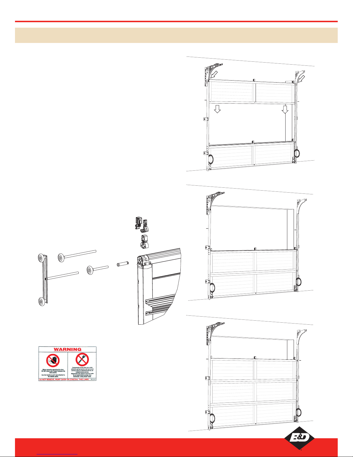
This procedure is the same for PFT, PFI & B&D Storm-Shield™
PFI doors.
Carefully lower the wheels of the bottom panel into the tracks. The
bottom door panel is to sit level in the door opening. The wheels
are to sit in the “V” groove of the vertical tracks and there should
be clearance between panel and tracks, see Figure 1.6.1.
Now you are ready to install the rest of the panels.
There is a link for every point where there is a stile, which should
all be folded down at this stage.
Insert panel into the guide engaging the wheels into the vertical
tracks, Figure 2.9.3, and nesting the panel onto bottom panels,
Figure 2.9.4. Starting at the centre, lift the panel enough to insert
the link, repeat this one at a time for the remaining links.
Repeat this procedure for all other panels with the exception of
the top panel which has externally mounted adjustable metal
hangers (Figure 2.6.3) these allow for forward and backward
adjustment of the top panel. When finally adjusted the additional
two locking fixings must be added, Figure 2.6.2.
NOTE: Ensure all white pins are inserted in PFT & PFI panel or
special screws if the panels are insulated, Figure 2.9.1.
FIGURE 2.9.3
FIGURE 2.9.4
FIGURE 2.9.5
FIGURE 2.9.2 LABEL
2.9 ADDING PANELS
NOTE: Ensure warning label is clearly visible.
FIGURE 2.9.1 ASSEMBLE LINKS
& PINS ONTO THE PANEL
18
Panelift® PFT, Panelift® Icon™ PFI, B&D Storm-Shield™ PFI and Insul-Shield™ Installation Instructions
Revision 9 - March 2016
Page 19
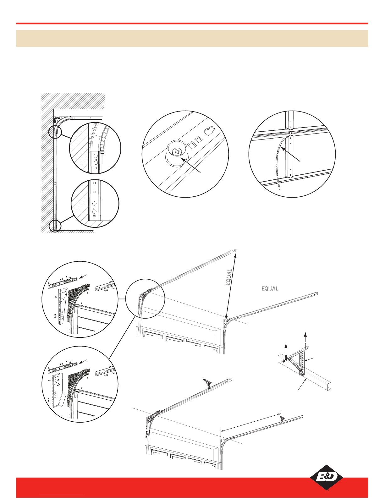
Assemble the track as shown in Figure 2.10.1, ensure that the plastic curve is aligned and butts up against the vertical track and
horizontal track snugly.
The horizontal tracks are identified by being the longer pair of tracks supplied and should be at least:
Door height + 350mm
2.10 INSTALLING HORIzONTAL TRACKS
The safety stops must always be fitted
at the end of the horizontal track to
prevent the panels from accidently
exiting track.
INSTALLING THE
SAFETY STOP
Track
Stop
The safety pull cord must always
be fitted to the door. Pass the cord
through the white hinge pin, adjust
length and tie in a knot at each end.
Alternatively fit ‘D’ handle.
INSTALLING THE SAFETY
PULL CORD OR ‘D’ HANDLE
Pull Cord
FIGURE 2.10.1 ASSEMBLING HORIZONTAL TRACK
EQUAL
EQUAL
Ensure a washer is
used under the wiz nut
FIGURE 2.10.2 BRACING
Fix to
Ceiling
Horizontal Track
Angle
¾ Door Height
FIGURE 2.10.3
SINGLE BRACE
Ensure a washer is
used under the wiz nut
19
Panelift® PFT, Panelift® Icon™ PFI, B&D Storm-Shield™ PFI and Insul-Shield™ Installation Instructions
Revision 9 - March 2016
Page 20
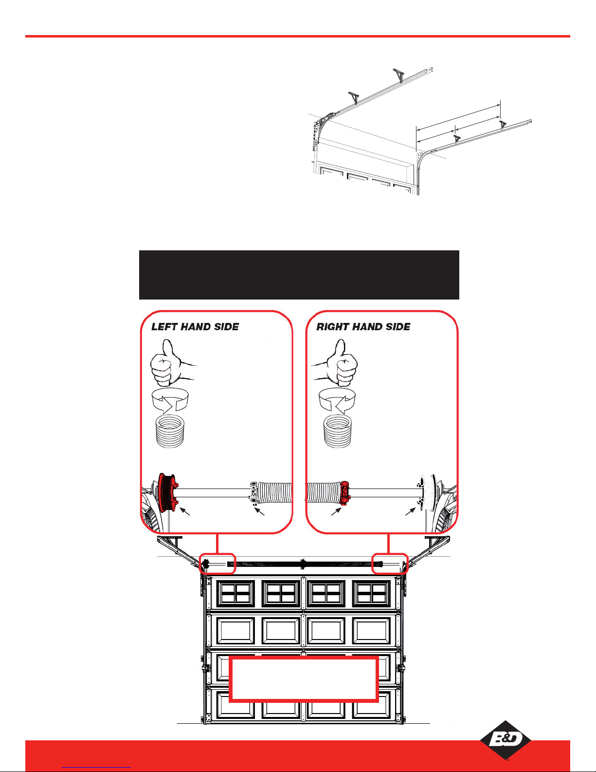
Before bracing the horizontal tracks, ensure that they are square
to the opening and level. To check whether your diagonals are
equal, measure from the top of the vertical track to the end of
the horizontal track on both sides. Check both sides. Adjust if
necessary and fix diagonal brace. Figure 2.10.1.
Use steel angle, Figure 2.10.2, to fix the horizontal tracks to
the building. Find a structurally sound location to fix your angle
to the ceiling or side wall. The track support must be located
approximately 3/4 height of the door, Figure 2.10.3. Failure to
do this will result in the tracks twisting out. For doors higher
than 2280mm and/or wider than 5000mm two supports will be
required, Figure 2.10.4.
Each installation must be assessed individually for ceiling fixing
requirements.
NOTE: For all insulated panels two (2) ceiling braces must be
fitted per horizontal track for all doors over 2400mm x 3000mm.
¾ Door Height
Equal
Equal
FIGURE 2.10.4
DOUBLE BRACE
FIGURE 2.10.5
These springs are Right
Hand Wound and can be
identified by the direction
of the curled fingers of the
Right hand when the thumb
is pointing up, matching the
same direction of the spring
end. The plugs in these
springs are painted Black
and go on the left hand side
of the door.
NOTE: Red cable drum
mounted on the left side
(standard headroom).
Springs & Drums are now colour coded
based on winding direction to match
international standards. Refer to notes when
using combo spring brackets.
INSIDE GARAGE LOOKING OUT
ATTENTION INSTALLERS!
NEW COLOUR CODING STANDARD FOR ALL B&D SECTIONAL DOOR SPRINGS
Red Cable Drum Black Cable DrumBlack Plug Red Plug
These springs are Left
Hand Wound and can be
identified by the direction
of the curled fingers of the
Left hand when the thumb
is pointing up, matching the
same direction of the spring
end. The plugs in these
springs are painted Red and
go on the right hand side of
the door.
NOTE: Black cable drum
mounted on the right side
(standard headroom).
20
Panelift® PFT, Panelift® Icon™ PFI, B&D Storm-Shield™ PFI and Insul-Shield™ Installation Instructions
Revision 9 - March 2016
Page 21
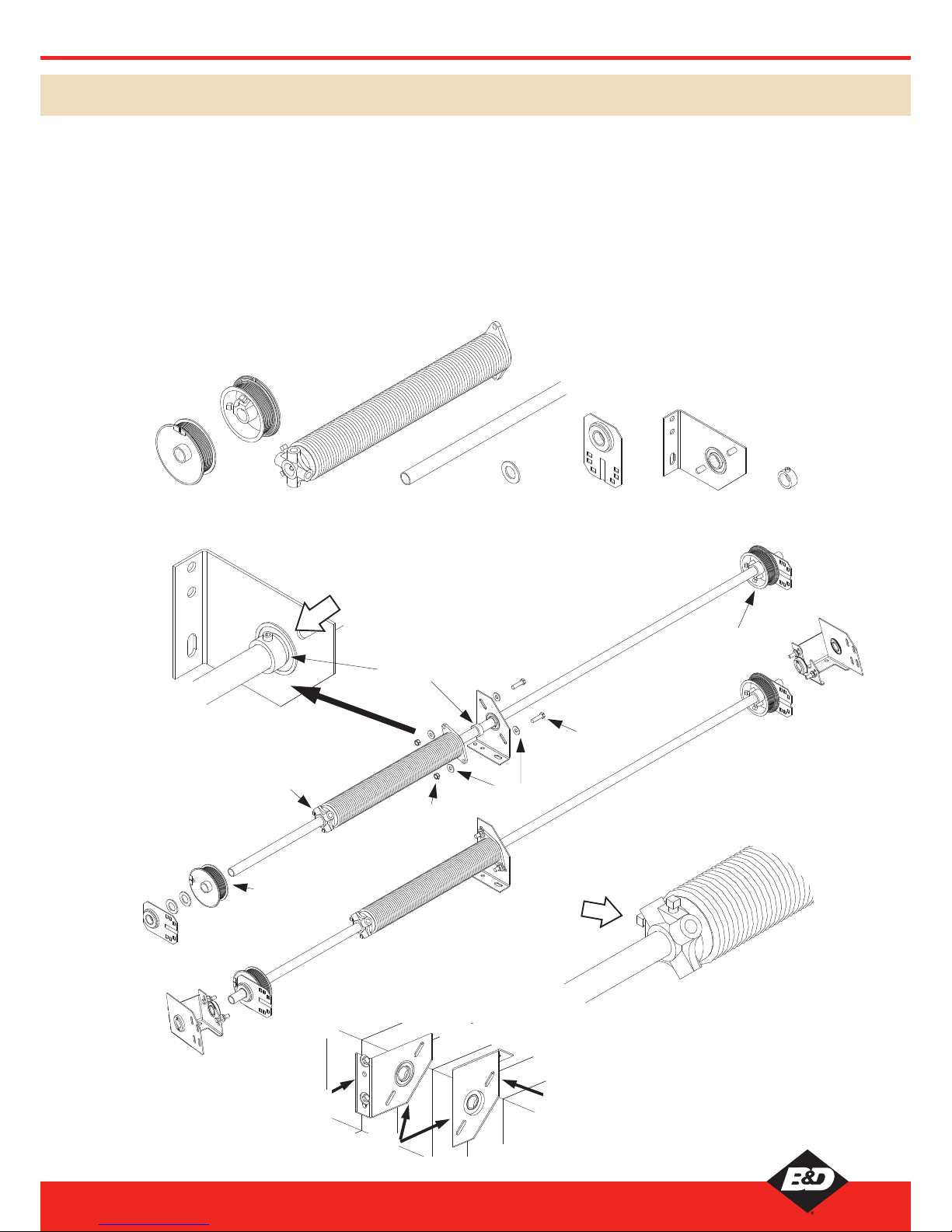
Place the torsion bar on the floor and position the lifting parts
in order. Place the spring anchor bracket onto the torsion bar,
positioning it approximately half way along.The cut off comer
should face the floor if mounted on the lintel, or if mounted on
the ceiling should face rearward, away from the lintel to allow
the panels to clear as the door operates, see Figure 37.
With single spring doors, slide a shaft collar against the spring
anchor bracket. The bearing flange in the spring anchor bracket
must face the spring. It may need to be reversed depending on
whether a left or right hand spring is supplied, see Figure 38.
The shaft collar is tightened against the bearing flange. Slide the
spring onto the torsion bar and over the shaft collar. A left hand
spring has a red winding plug, and should be fitted to the left
hand side of the spring anchor bracket. A right hand spring has
a black winding plug. The winding plugs should face away from
the spring anchor bracket, see Figure 39.
NOTE: It is important to use 2 of the 4 1¼ inch square necked
bolts to secure each side bearing plates in position.
Refer to page 28 when adding spring tension.
Cable Drums
Red* & Black*
Spring Axle
Shaft
Collar
Washer Side Bearing
Brackets
Spring Anchor
Bracket 65mm
Shaft Collar to be butted up against
Anchor Bracket and fixed to axle
on spring side of Anchor Bracket
DO NOT TIGHTEN
YET
FIGURE 38
FIGURE 39
Cable Drum marked
with Red Paint
Winding Plug marked
Refer to page 14
Cable Drum marked
with Black Paint
Bolt 3/8”
Nut 3/8”
Washer 3/8”
Shaft Collar
Note regarding Part Numbers
Springs and Cable Drums vary
from across different door sizes
FIGURE 37
Fixed to
Ceiling
Fixed to
Wall
Cut Corner facing down
FIGURE 2.11.1 PARTS NEEDED - SINGLE SPRINGS
2.11 STANDARD SPRING COUNTERBALANCE SYSTEM
21
Panelift® PFT, Panelift® Icon™ PFI, B&D Storm-Shield™ PFI and Insul-Shield™ Installation Instructions
Revision 9 - March 2016
Page 22

With two springs no shaft collar is necessary. Place the cable drum onto the torsion bar with the red cable drum on the left side and
the black cable drum on the right side as in Figure 41.
The set screws on the cable drums should face inwards see Figure 40. Place the two 3 mm cable drum spaces on each side. Then
the side bearing brackets are positioned outside the cable drum spacers with the flange facing outwards.
NOTE: It is important to use 2 of the 4 1¼ inch square necked bolts to secure each side bearing plates in position.
Refer to page 28 when adding spring tension.
Cable Drums
Red* & Black*
Springs
Red* & Black*
Axle Washer
Side Bearing
Brackets
Spring Anchor
Bracket 65mm
*Items marked as ‘Red’ are placed on the left hand side of the door
looking out, ‘black’ on the right hand side for standard installation
DO NOT
TIGHTEN
YET
FIGURE 40
FIGURE 41
Cable Drum marked
with Red Paint
Winding Plug marked
Refer to page 14
Winding Plug marked
Refer to page 14
Cable Drum marked
with Black Paint
Bolt 3/8”
Nut 3/8”
Washer 3/8”
Washer 26
44.5mm
Note regarding Part Numbers
Springs and Cable Drums vary
from across different door sizes
A
B
NOTE: When Combo spring brackets are used
move spring A to spring B position and spring
B to A position and attach to combo bracket.
FIGURE 2.11.2 AXLE ASSEMBLY
PARTS NEEDED - DOUBLE SPRINGS
22
Panelift® PFT, Panelift® Icon™ PFI, B&D Storm-Shield™ PFI and Insul-Shield™ Installation Instructions
Revision 9 - March 2016
Page 23
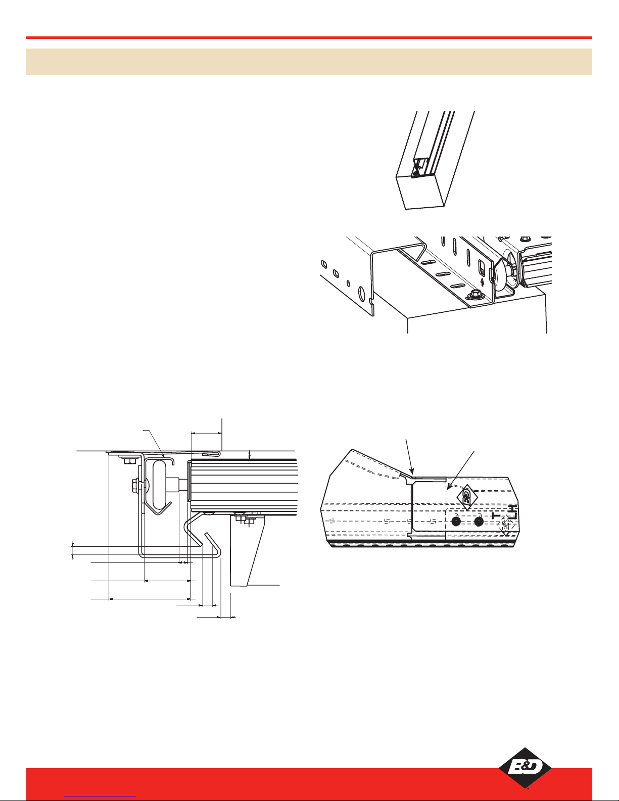
2.12 FITTING B&D STORM-SHIELD™ PFI TRACKLOCKS
Whilst fitting tracklocks is shown here it is preferable to leave
until the door is fully functioning and you are satisfied with the
operation.
FOR SMALL CURVE
• The top of the Tracklock must be cut back 60mm as
indicated at Figure 2.12.3.Only after removing this material
can the tracklock be cut to length from the bottom as a pair.
• After cutting, align the Tracklock with the Jamb Bracket.
The top of the cut Tracklock should be a snug fit with the
bottom of the top track bracket. Figure 2.12.3.
FOR LARGE CURVE
• if to long only cut as a pair from the bottom. Align the
Tracklock holes with the Jamb Bracket as shown on page
12. The top of the uncut Tracklock should be a snug fit
with the bottom of the top track bracket. Figure 2.12.3.
Attach via the key hole slots and ensure the clearance is correct
refer Figure 2.12.2.
When satisfied with clearances and operation a minimum of 5
pairs of 1/4 bolts and wiz nuts must be fitted to every metre of
track height.
When finally satisfied fit all substrate fixings and washers as
requested by the DTCM compliance details.
FIGURE 2.12.1
FIGURE 2.12.2 WHEEL-AXLE
FINAL B&D STORM-SHIELD™ PFI
WITH TRACKLOCK POSITIONING
10
10
30
8
TRACK
A
C
B
E/F
FIGURE 2.12.3
If using a small
curve cut at 60mm
before cutting to length
Bend and round
this edge if required
to align joint
23
Panelift® PFT, Panelift® Icon™ PFI, B&D Storm-Shield™ PFI and Insul-Shield™ Installation Instructions
Revision 9 - March 2016
Page 24
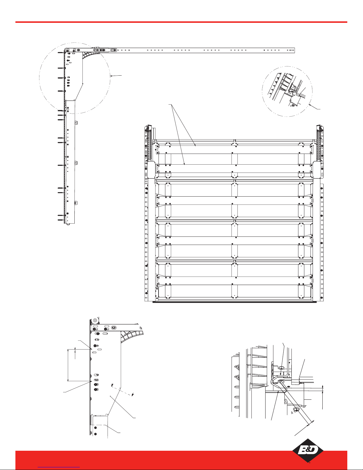
A = 170 (FTS), 190 (FTL)
LENGTH VERT-TRACK = DOOR HEIGHT - A
LEFT SIDE VIEW PROJECTION
D
REAR VIEW PROJECTION
INSTALL REO LAST
E
FIGURE 2.12.5
FIGURE 2.12.6
FIGURE 2.12.7
FIGURE 2.12.4
TOP-PANEL
HOOK PLATE
TOP-PANEL
TRACKLOCK
8-11
8-11
PROJ-VIEW
A
10
E
DASH-LINE INSIDE INDICATES APPROXIMATELY
TO CUT HERE FOR SMALL CURVE
ADJUST HOOK PLATE ALIGNED
WITHIN TRACKLOCK
TOP OF
VERTICAL TRACK
TOP OF PANEL
24
Panelift® PFT, Panelift® Icon™ PFI, B&D Storm-Shield™ PFI and Insul-Shield™ Installation Instructions
Revision 9 - March 2016
Page 25
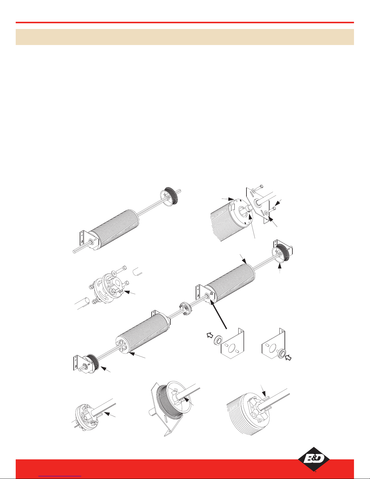
For very large doors whose springs simply become too large
and heavy to handle in a complete single axle assembly, two
solid torsion axles are supplied with a coupling to allow easier
installation.
Assemble both axle assemblies on the floor, only one Spring
Anchor Bracket is used, the other Spring Anchor Bracket is
fixed in position at the wall. Figure 48 shows the right half
of the axle assembly as it should look on the floor. The shaft
collar should be butted up against the Spring Anchor Bracket
opposite of the spring and then firmly fixed into place.
Lift and thread the Axle on the Cable Drum side through the
mounted Spring Anchor Bracket and fix the loose Spring
Anchor Bracket securely to the lintel, you may need to rest the
assembly end on the ladder or scissors lift.
Assemble the Torsion Shaft Couple engaging both left and
right hand axle assemblies as shown in Figure 49, it will
not be necessary to tighten the bolts as yet, allowing some
adjustment. The axles should be flush with each couple
allowing free rotation to occur.
Secure the springs assemblies to the Spring Anchor Brackets
as shown in Figure 50. The complete assembly should look like
Figure 51 by this stage. Cut the key to the required lengths and
then insert into the slots as shown in Figure 52 for the couple.
Attach lifting cable to cable drum in the same fashion
described on page 23 and adjust as described, however a key
needs to be inserted into place as shown in Figure 53 when
tightening the grub screws, the couple should allow some
adjustment before tightening the bolts connecting the two
axles fully.
The springs are tensioned in the same fashion as described on
page 28, however with the additional step of insertion of keys
into the slots which should be lined up between the winding
drum and axle then fixed firmly in place with grub screws,
Figure 54.
FIGURE 48
FIGURE 52 FIGURE 53 FIGURE 54
FIGURE 49
FIGURE 50
FIGURE 51
Threaded
Hole
Insert key then fix
into place with grub screw.
Cable Drum marked
with Red Paint
Winding Plug maeked.
Refer page 14.
Winding Plug marked.
Refer page 14.
Cable Drum
marked with
Black Paint
Torsion Shaft
Couple
Note regarding Part Numbers
Springs and Cable Drums vary with
door size
Torsion Shaft
Key
Torsion Shaft
Key
Torsion Shaft Key
Bolt 3/8”
Washer 3/8”
Check the orientation of the bearings in
Spring Anchor Brackets. The Flange side
must be on the same side as the Shaft
Collar, Figure 50.
The bearing can be ‘popped’ out and
reversed, if this is not the case.
Shaft Collar
Springs are differentiated
by the color of the winding
plugs, red or black. Refer
page 14.
2.13 LARGE DOORS - TwO PIECE SHAFTS
25
Panelift® PFT, Panelift® Icon™ PFI, B&D Storm-Shield™ PFI and Insul-Shield™ Installation Instructions
Revision 9 - March 2016
Page 26
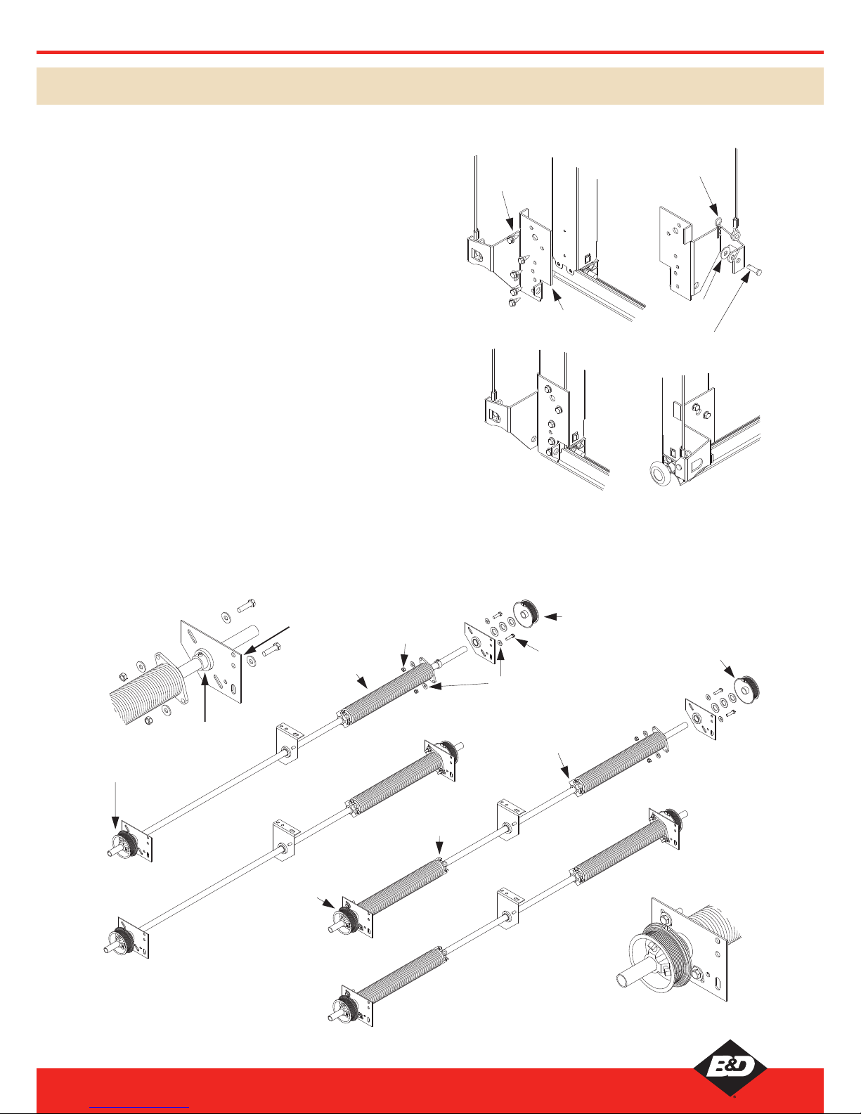
BOTTOM HANGERS: Find the Low Lift Bottom Hangers, the cables,
Clevis Pins, Humpback Spring Pins, and washers. Assemble Low Lift
Bottom Hangers as shown in Figure 55 A. Then assemble onto the
bottom panel as shown in Figure 55 B.
CURVE ASSEMBLY: Insert plastic curve onto the inside of the top
brackets and secure onto bracket using 2 nuts and bolts per curve
insuring that the “V” of the vertical track lines up with the curve.
From the Rear Torsion Parts Bag assemble each pulley wheel with the
spacers sandwiched between opposite handed corner brackets and
held with a nut, bolt and washer as shown in Figure 60. The two corner
brackets should overlap and be secured into place. Secure against the
wall in 3 points and connect to vertical tracks at two points as shown.
AXLE ASSEMBLY: The axle assembly for rear torsion is different in
that the Side Bearing Brackets are replaced with Sheave Bracket Rear
Torsion off which the springs are mounted and which are connected
to the free ends of the horizontal tracks rather than directly over the
opening.
Figure 57 illustrates the assembly of single spring rear torsion
installation. A shaft Collar is still required and fixed on the spring side
of the Flat Spring Anchor Brackets as shown in Figure 56.
Figure 58 demonstrates a double spring rear torsion installation, which
like a single spring rear torsion door has the springs mounted off the
sides on the Flat Spring Anchor Brackets rather than the centre.
For both variations the cable drums are mounted on the outside of the track and brackets with the grub screws pointing away from
the centre as shown in Figure 59 Additionally the red and black springs are put on opposite sides of the axle than for a standard
installation.
FIGURE 56
Shaft Collar
Sheave Bracket
Rear Torsion
FIGURE 57
FIGURE 58
FIGURE 59
‘Red’ Spring
‘Red’ Cable Drum
‘Black’ Cable Drum
NOTE - The ‘Red’ and “black’
colour coded Springs and
Cable Drums are put on the
opposite sides to that of a
standard installation
Cable Drum mounted
outside the bracket with
Screws pointing away
from centre
Cable Drum
marked with
Red Paint
Winding Plug
marked with red
paint denoting
‘Red’ Spring
Winding Plug
marked with red
paint denoting
‘Black’ Spring
Cable Drum
marked with
Black Paint
Bolt 3/8”
Nut 3/8”
Washer 3/8”
FIGURE 55
A
B
C
Bottom Hanger BB5R
Left Hand
Right Hand
Tekscrew SF Split Pin
Washer
Clevis Pin
FIGURE 2.14.1 BOTTOM HANGERS
FIGURE 2.14.2 AXLE ASSEMBLY
2.14 REAR TORSION INSTALLATION (PFT & PFI ONLY)
26
Panelift® PFT, Panelift® Icon™ PFI, B&D Storm-Shield™ PFI and Insul-Shield™ Installation Instructions
Revision 9 - March 2016
Page 27
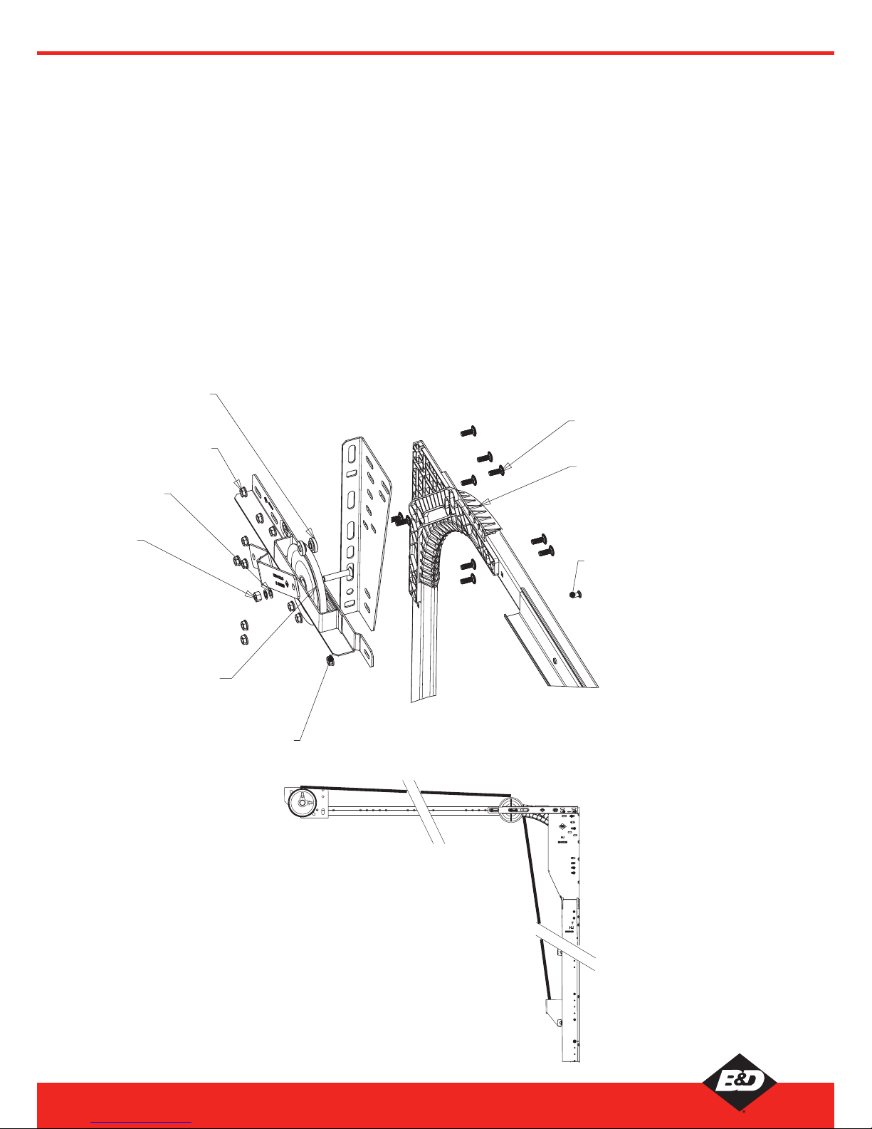
TORSION BAR INSTALLATION: Ensure that the ceiling fixing points are suitable to accept the weight of the torsion and spring
assembly.
Fix the flat spring anchor brackets to the free ends of the horizontal tracks, Figure 61. Rest the assemble torsion bar on top of the
tracks, then slide one axle end into one bearing and then through the other bearing. Secure the centre bearing plate into a solid
foundation either directly or by the use of suitable steel angle.
Now secure the springs to the spring anchor bracket using 3/8” x 1½” hexagonal head bolts and 3/8” washers and nuts.
Unwind the lifting cable on both sides and thread the cable behind the wheel axles around the ring on the bottom hanger, through
between the pairs of corner brackets around the pulley wheel and over to the rear drums, Figure 61.
Attach the lifting cable to the cable drum by slipping the cable into the slot on the outside groove. (The ferrule will prevent the cable
from coming out). Wind the cable by hand turning away from the door in an up and over direction. Once the cable is taut, slide the
cable drum against the end bearing bracket and tighten the 9.5 mm set-screws securely to the torsion bar. Be careful not to overtighten the set-screws.
Refer to page 28 when adding spring tension.
FIGURE 60
FIGURE 61
NUT 1/4" FLANGED 0T2702
TOP BRACKET LH ASSEMBLY
WASHER
000785
NUT FLANGED
5/16"-UNC 45713
140 mm SHEAVE
PULLEY 0T5251
PLASTIC CURVE OT3170
BOLT SQ NECK
5/16"-UNCx7/8" 0T2714
NUT
3/8"-UNC
006553
BOLT 1/4"x1/2"-UNC 0T2709
SPACER 0T5252
TOP BRACKET LH ASSEMBLY
(parts may differ to those shown)
27
Panelift® PFT, Panelift® Icon™ PFI, B&D Storm-Shield™ PFI and Insul-Shield™ Installation Instructions
Revision 9 - March 2016
Page 28
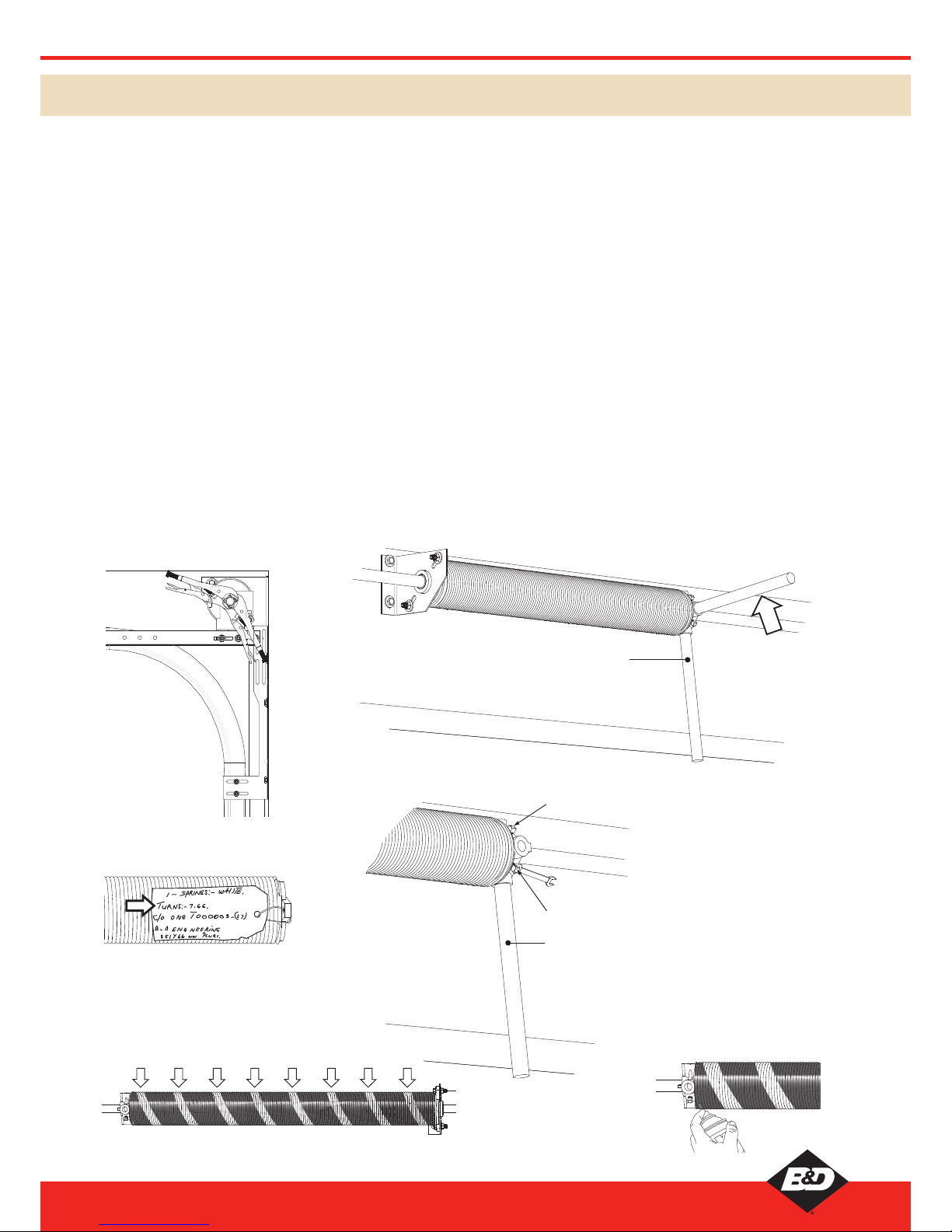
Secure the torsion bar to prevent any rotation, as shown in
Figure 2.15.1.
WARNING: TORSION SPRINGS CAN CAUSE SERIOUS
INJURY! IF YOU ARE NOT SURE, STOP NOW! ASK
TRAINED PERSONNEL.
The number of turns required for each spring is shown on a
paper tag attached to the springs Figure 2.15.2. If the spring
is required to have 7.5 turns for example, these are full turns
and are equivalent to 30 quarter turns. Alternatively, a line is
painted along every spring. If the spring is turned for example
8 times, then 8 lines can be counted along the spring, See
Figure 2.15.3.
WARNING: ONLY USE AUTHORISED WINDING BARS AS
LISTED ON PAGE 5.
Turn the spring by inserting winding bars into the winding plug
holes and wind up in an up and over direction towards the
ceiling, Figure 2.15.4. Once you have completed the amount of
turns required, remove one winding bar then tap the remaining
bar back towards the spring anchor bracket if spring snaking
occurs. Now you can tighten the two set screws with an open
ended spanner, Figure 2.15.5. Again be careful not to overtighten the set screws.
Repeat this procedure if there is more than one spring but
remember, always wind the springs, whether left or right hand,
in an up and over direction towards the opening.
WARNING: KEEP HANDS CLEAR OF THE SPRING AND THE
SPRING WINDING PLUG AT ALL TIMES.
Double check that the set screws are properly tightened, before
removing the restraints on the torsion bar.
Test the balance of the door. Put the door into the open
position and view along the horizontal tracks. Check that
the clearance in the vertical tracks (5-10mm) is also in the
horizontal tracks. If you find that the door is binding, open out
the horizontal tracks slightly to create the correct tolerance.
Once satisfied that the operation of the door is as near perfect
as possible, check that all nuts and bolts are tight and oil
the springs full length to prevent noise and reduce friction,
‘TAL 5’ or similar oil rich lubricant in a pressure spray can is
acceptable, Figure 2.15.6.
FIGURE 2.15.1
SECURING TORSION BAR
FIGURE 2.15.2 SPRING LABEL
FIGURE 2.15.4 ADDING TENSION
Always have one
winding bar engaged
and firmly held
while turning
Tension the
springs by
winding in the
up direction
FIGURE 2.15.5 TIGHTENING GRUB SCREWS
Grub screw 2
Grub screw 1
Use a spanner to
tighten grub screw
Maintain tension
while tightening both
screws, these must be
very firmly tightened
but not to the point of
deforming the axle
FIGURE 2.15.3 COUNTING THE TURNS
123456
78
2.15 ADDING TENSION TO SPRING
FIGURE 2.15.6
LUBRICATING SPRINGS
28
Panelift® PFT, Panelift® Icon™ PFI, B&D Storm-Shield™ PFI and Insul-Shield™ Installation Instructions
Revision 9 - March 2016
Page 29
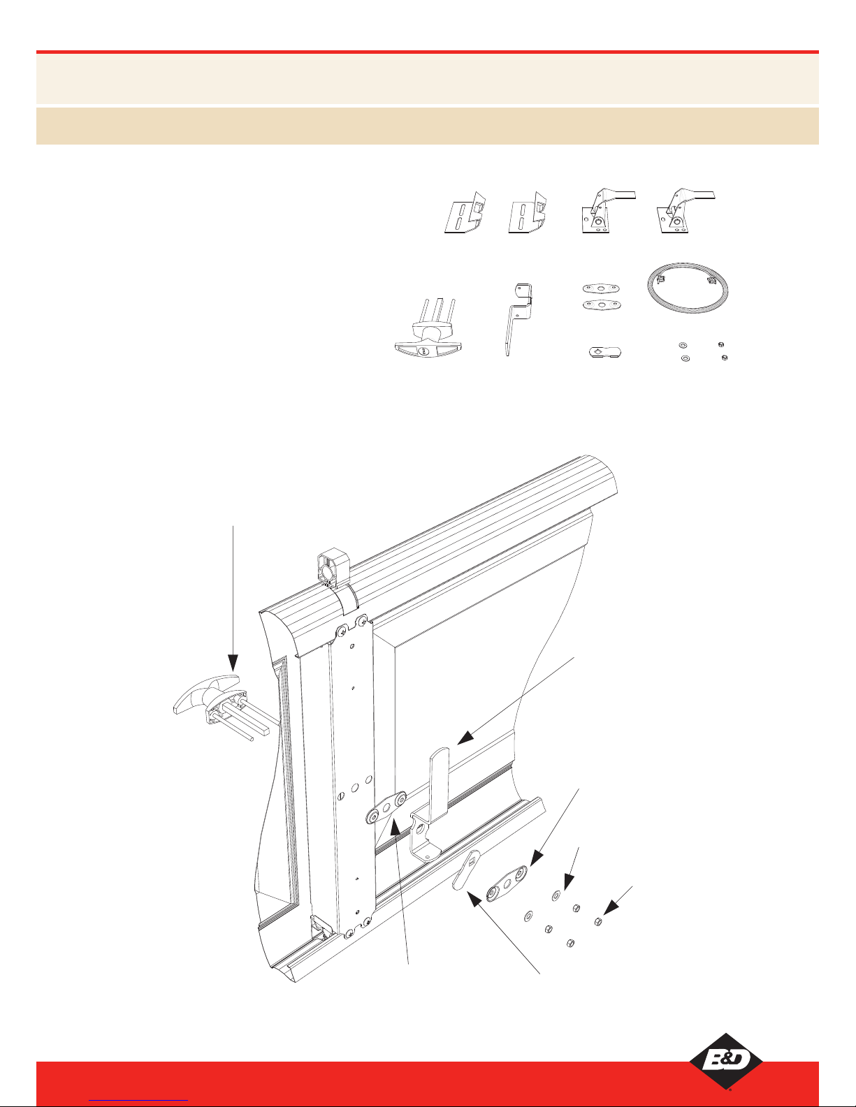
NOTE: In coffin garages (those with no access other
than the garage door), the lock handle should be
installed immediately after fitting the lock panel.
The lock handle is to be fixed to the middle of the
second panel. Using lock plate as a guide, centre on
central end stile and drill through the end stile and the
panel using a 1/2” (13 mm) drill bit for the large hole
and a 3/16”(5 mm) bit for the two holes on either side.
Fit the “T” handle to the panel by inserting the lock
shaft and the two 3/16” thread bolts into the panel
from the outside, through the lock muntin. Attach
the 3/16” or 4.7 mm nuts and washers securing the
‘T’ Handle in place. Next insert the lock guide plate
(dimples facing away from door) followed by the
internal handle, the lock cam and the second guide
plate (dimples facing the door). Lock together with
3/16” nuts and washers, see Figure 3.1.2.
Lock Strikes
External Lock
Handle
Internal Lock
Handle
Lock Cam
Lock Guide Plates
Lock Cable
Washer Nuts
Lock Catch
FIGURE 3.1.1 PARTS
FIGURE 3.1.2 LOCK ASSEMBLY
External Lock Handle
Lock Guide Plate
Internal Lock Handle
Lock Cam
Lock Washer
Nut 4mm
Lock Guide Plate
3.0 OPTIONAL COMPONENTS
3.1 LOCK INSTALLATION (PFT & PFI ONLY)
NOT SUITABLE FOR
B&D STORM-SHIELD
™
29
Panelift® PFT, Panelift® Icon™ PFI, B&D Storm-Shield™ PFI and Insul-Shield™ Installation Instructions
Revision 9 - March 2016
Page 30
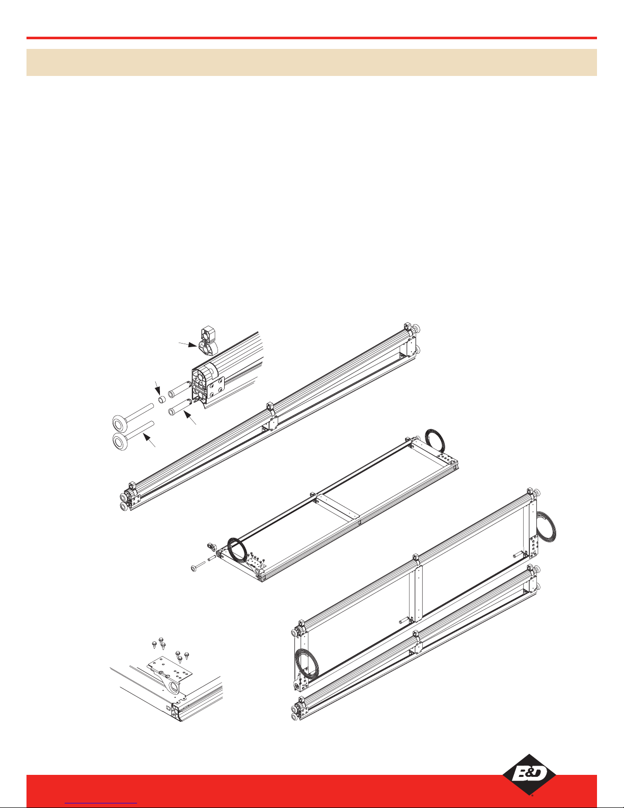
Tapers are accomplished using a small customised panel,
which results in a slight variation in the installation process,
please familiarise yourself with the standard installation before
proceeding.
The Lifting gear is now attached to a standard central panel,
which can be identified by a) having no weatherstrip at the
bottom and b) having the slots on the bottom edge to connect
with the tapered panel.
Tracks are assembled as standard with the only difference being
that one vertical track needs to be cut down to accommodate the
uneven floor. Both vertical tracks need to start from the ground
and end level with each other. Cut the track as necessary from
the ground end.
Assemble the tapered panel as shown in Figure 78 - the 2
spacers required are to be cut 10-12mm long from a white link
pin and fitted one to each side as shown. Insert into tracks as
shown in ‘Installing Bottom Panel’ on page 19.
The lifting panel is different from that shown on page 12 in that
there is no weatherstrip (it’s part of the taper panel) and slots are
present to connect to the tapered panel.
Assemble bottom hanger as shown in Figure A and B on page 13.
Modify bottom hanger as in Figure 79. The bottom hanger will thus
sit slightly higher up the panel than normal, so as not to interfere
with hinging movement. Also no wheel or links are connected at
the bottom as shown in Figure 80 when these as attached.
Simply assemble lifting panel onto the tapered panel as standard
as shown on page 19 ‘Installing Additional Panels’, see Figure 81.
3.2 HINGED TAPERS
FIGURE 79
FIGURE 80
FIGURE 81
FIGURE 78
Hinge Pin
Spacer
Wheel Axle
Hinge Link
30
Panelift® PFT, Panelift® Icon™ PFI, B&D Storm-Shield™ PFI and Insul-Shield™ Installation Instructions
Revision 9 - March 2016
Page 31

LIFTING CABLES LOOSE WHEN DOOR IS OPENED
• Cable drums have slipped
• Diagonals out of square
• Check length of lifting cables
TORSION BAR MOVING
• Cable drums not adjusted correctly
• Springs not adjusted correctly
• Shaft collar not fitted (single spring)
• Check end bearing brackets are square and vertical
DOOR WILL NOT HOLD UP IN OPEN POSITION
• Adjust tension on door
• Incorrect springs
• Panel reinforcing fitted incorrectly
DOOR NOT LEVEL
• Check water level marks are correct
• Lifting cable not equally taut
DOOR MOVING TO ONE SIDE
• Clearances incorrect
• Cable drum not hard up against end bearing brackets
DOOR PANELS JAMMING/RUBBING ON TRACKS
• Incorrect clearance between wheel and vertical track
• Door out of level
• Cable drum not lined up correctly
• Vertical tracks not parallel
• Lifting cables slipping
DOOR HARD TO LIFT
• Incorrect tension on springs
• Spring may have slipped on set screws
• Wrong spring
• Check all panel reinforcing on door panel
4.0 TROUBLESHOOTING
If all points have been checked please seek manufacturer for service.
COMMON SPRING PROBLEMS
SYMPTOM CAUSE SOLUTION
Door raises from the floor and
hangs down in opening
Cable length too long with cable not on high
portion of drum
Shorten cable length until the cable rolls onto
the flat portion of the drum when the door
starts into the horizontal position
Springs may be too strong (too short) Replace spring
Wrong cable drums for springs (too small) Replace cable drums
Door lifts from the floor and
runs away at the top
Door is over tensioned. Too many turns on
spring or wrong spring
Ensure that the correct spring is supplied (if not
replace) and that it has the correct number of
turns applied
Wrong cable drums for spring, (too small) Replace cable drums
Door falls to the floor and
hangs down in the opening
Door is under tensioned too few turns on spring
or wrong springs
Ensure that the correct spring is supplied (if not
replace) and that it has the correct number of
turns have been applied
Wrong cable drums for springs (too large) Replace cable drums
Door falls to the floor and
runs away at the top
Lifting cable may be too short for high lift cable
drum or vertical lift drum and is sitting too high
on the spiral portion of the drum
Increase the cable length to bring the cable
down lower on the spiral
Torsion springs too long Shorten springs
Door balances at the floor but
runs up or down in between
Cables in wrong position on spiral of the drums Adjust cable length
Poor balance throughout Winding spring in wrong direction Wind in correct direction
Door weight incorrect Supply correct springs
Springs binding Fit torsion bar collar
Lubricate springs
Door not level Cable lengths are equal
Equal turns on both springs
Level door during installation
31
Panelift® PFT, Panelift® Icon™ PFI, B&D Storm-Shield™ PFI and Insul-Shield™ Installation Instructions
Revision 9 - March 2016
Page 32
GENERAL CARE OF YOUR PANELIFT
CLEANING
COLORBOND® & COLOURED STEEL FINISH Your B&D
Panelift has been pre-painted with a silicone modified polyester
formulation, which is one of the best paint films commercially
available today. However, all exposed surfaces require some
attention to guard against the premature onset of corrosion
and any other harmful atmospheric effects. In our atmosphere
there are harmful deposits that gather on the door surface and
if not removed regularly, will seriously affect the appearance
and life of the door.
Washing of the door with clean water and a cloth every 14 days
is recommended – particular care should be taken to clean
areas of the door not normally washed by rain.
LOCK
Your lock does not require special maintenance, however, if the
keyway becomes stiff, the application of powdered graphite is
recommended – do not grease or oil the lock.
WARNING! Do not disassemble the lock mechanism and do
not allow paint to enter the lock keyway.
HINGES & HANGERS
Plastic hinges – no lubrication is generally required, however
silicon spray or lithium grease may be used if necessary.
CABLES
Check the cables regularly for corrosion, fraying or tangling, if
any of these are evident call your service provider.
REGULAR MAINTENANCE REQUIRED
B&D recommends that you check the operation of your
Panelift at least every six months (more regularly in extreme
environments or frequent use). The effort required to manually
open and to manually close the door should be about the same
(if door has an automatic opener, put into manual mode before
testing door).
If the door is difficult to operate in either direction (up or down)
then check that the inside surfaces of the guides are clean and
free of obstructions.
If the door is still difficult to operate, then your door will need
a service to adjust the spring tension and possibly other
operational parts of the door.
This service should only be carried out by an experienced door
technician, using the correct tools.
If you have an automatic opener fitted to your door, it is
particularly important that you ensure the optimum operation
of the door, otherwise you may reduce the effective life of the
opener.
To keep your door running well, it is recommended that your
door be serviced, by an experienced door technician, every 12
months (more regularly in extreme environments or frequent
use), or earlier if required.
SPRING TENSION
It is natural for springs to lose tension over time. When spring
tension is adjusted or when your door is first installed it is usual
to apply a little more tension than is required for balanced
operation, to allow for the normal “settling in” of the springs.
Lightly lubricate to prevent friction between the coils.
WARRANTY
Warranty conditional on proper care as recommended above.
Full details of the warranty are available from www.bnd.com.au
5.0 AFTER INSTALLATION CARE
32
Panelift® PFT, Panelift® Icon™ PFI, B&D Storm-Shield™ PFI and Insul-Shield™ Installation Instructions
YOUR REPRESENTATIvE IS
New South Wales:
34 Marigold St, Revesby 2212. Phone: (02) 9722 5555
Queensland:
17 Oasis Court, Clontarf 4019. Phone: (07) 3883 0200
Newcastle:
Unit 1/108 Mitchell Rd, Cardiff NSW 2285. Phone: (02) 4956 8533
Victoria:
147-153 Canterbury Rd, Kilsyth 3137. Phone: (03) 9237 7766
South Australia:
23 Frederick Rd, Royal Park 5014. Phone: (08) 8440 4747
Western Australia:
96 Mulgul Rd, Malaga 6090. Phone: (08) 9247 8777
International/Export:
34 Marigold St, Revesby 2212. Phone: +61 (0)2 9722 5555
B&D Doors Office Locations:
www.bnd.com.au
Prefixed trademarks are the property of B&D Australia Pty Ltd
B&D Doors & Openers is a division of B&D Australia Pty Ltd
ABN 25 010 473 971
Copyright 2014 B&D Australia Pty Ltd.
 Loading...