

Page 1

1
BD FACSort System
After completing this module, you will be able to:
• Describe the BD FACSort™ system and how it works.
• Perform instrument startup and shutdown procedures.
• Describe instrument maintenance procedures.
BD FACSort System 337452 Rev. A
Page 2
2
BD FACSort System
The BD FACSort™ system is an automated flow cytometer and cell sorter. It analyzes
cells as they pass through a focused laser beam one at a time in a moving fluid stream. A
BD FACSort flow cytometer can be used for routine research applications,
immunophenotyping, and DNA cell-cycle analysis. In addition, the BD FACSort flow
cytometer allows you to identify and sort (isolate) a subpopulation from your sample.
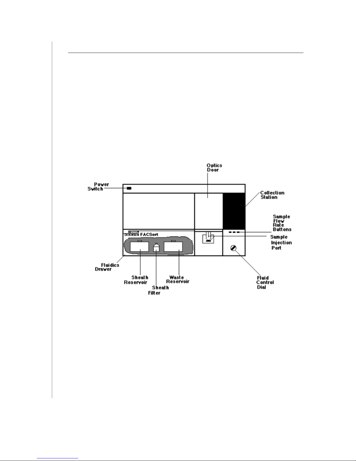
The BD FACSort system consists of a sensor module (Figure 3-1), computer module,
and several software packages. Many of the cytometer functions are controlled by the
software.
Cytometer
Figure 3-1 BD FACSort Sensor Module
Power Switch
This switch, located on the upper left corner of the instrument, turns the instrument on
and off.
BD FACSort System 337452 Rev. A
Page 3
3
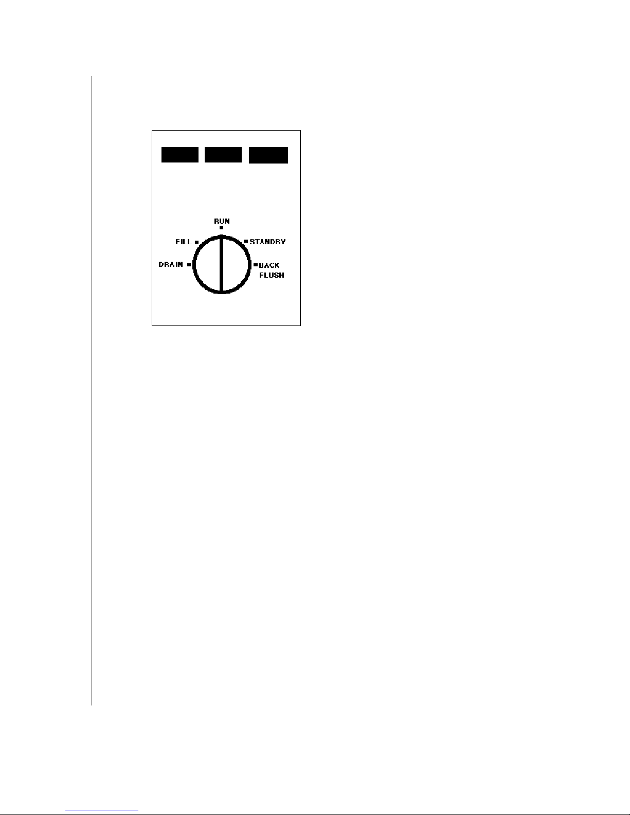
Fluidics Control Panel
This panel consists of the fluidics control dial and the sample flow rate buttons.
lolloLO
MED HI
Fluidics Control Dial
This rotary dial allows you to select from five fluidic modes.
DRAIN —forces liquids out of the flow cell and fluid lines leading to the waste.
FILL —fills the flow cell and fluid lines with sheath fluid at a controlled rate, which
prevents bubble formation.
RUN —pressurizes the sample tube to transport the cell sample suspension through the
sample injection tube and into the flow cell. When a tube is not on the Sample Injection
Port (SIP), the cytometer goes into auto Standby. Sheath flow is restricted and laser
power is lowered.
STANDBY —stops sheath flow and lowers laser power to conserve sheath fluid and
prolong laser life
• Hard STANDBY —When the fluid control dial is manually turned to STANDBY,
all fluid valves are closed except for one valve that vents the sample test tube air
pressure to the atmosphere. Additionally, the laser input current is reduced to a
standby level.
• Auto STANDBY —If the instrument is in RUN and the sample test tube is
removed, the instrument goes into autostandby. Twelve seconds later, the system
shuts off the sheath flow by means of a pinch valve between the flow cell and the
waste reservoir. Additionally, the laser input current is reduced to a standby level.
In this mode, back pressure is maintained to flush the sample injection tube. The
system returns to RUN mode when you reinstall the sample tube. The pinch valve
is opened and the laser returns to full power.
BD FACSort System 337452 Rev. A
Page 4
4
BACKFLUSH —reverses the flow of sheath fluid and flushes fluid out of the sample
injection tube to remove clogs.
Sample Flow Rate Buttons
Three buttons allow you to select the sample flow rate.
• LO —12 µ L/min of sample through the flow cell
• MED —35 µ L/min of sample through the flow cell
• HI —60 µ L/min of sample through the flow cell
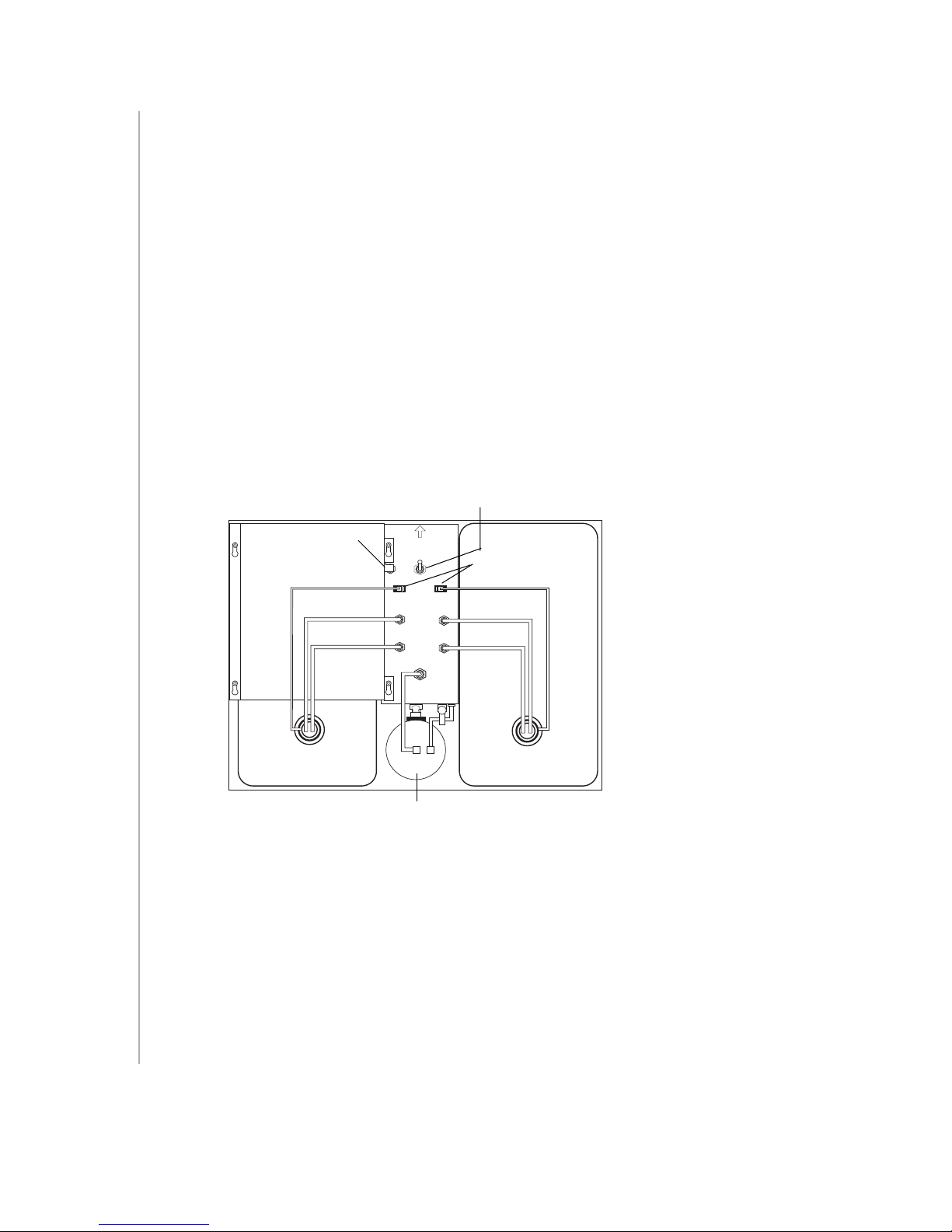
Fluidics Drawer
The fluidics drawer (the lower left panel of the instrument), slides out for easy access to
the fluidics reservoirs and sheath filter.
vent valve toggle switch
tab
metal bracket
sheath tank waste tank
VENT VALVE
PRESS TO
RELIEVE PRESSURE
J69 J70
SHEATH
SALINE
FILTER
sheath filter
probe sensor connectors
WASTE
Sheath Reservoir
This 4-liter container, located on the left, holds enough sheath fluid for approximately 3
hours of run time. It is equipped with a low-level fluid detector which indicates via
software a near-empty condition. A metal bracket fits over the reservoir to secure the
tank.
BD FACSort System 337452 Rev. A
Page 5

5
Waste Reservoir
This 4-liter container, located on the right, collects the fluid waste. A fluid-level detector
indicates, via software, a near-full condition.
CAUTION If potentially biohazardous materials are run through the instrument, treat this
material as biohazardous waste.
Sheath Filter
This 0.22-µm filter cleans the sheath fluid before it enters the flow cell. This reduces the
amount of debris in the sheath fluid.
Vent Valve Toggle Switch
A switch that, when set in the direction of the arrow, relieves the sheath reservoir of air
pressure. This allows for the removal of the reservoir when refilling.
Air Filter
This component filters the air that cools the laser.
Optics Door
This door shields the compartment which houses the flow cell assembly. Open this door
to view the flow cell while draining and filling.
Flow Cell
This quartz cuvette is where the laser intercepts the sample stream. The dimensions are
430 µm x 180 µm.
Sample Injection Port
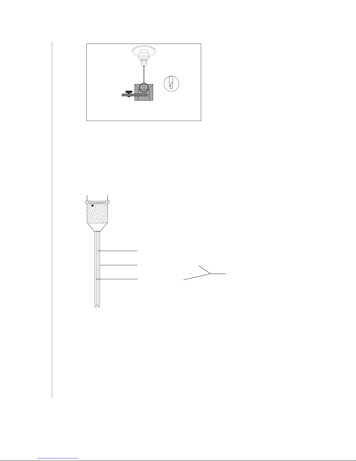
The SIP is the area where the sample tube is installed. It consists of the sample injection
tube through which the sample travels to the flow cell, the droplet containment system,
and the tube support arm (Figure 3-2 on page 6).
BD FACSort System 337452 Rev. A
Page 6
6
Figure 3-2 Sample Injection Port
Sample Injection Tube
This is the stainless steel tube that carries the cells from the sample tube to the flow cell.
The tube is covered with an outer sleeve that serves as part of a droplet containment
system. See Figure 3-3. The droplet containment system employs a vacuum pump to
aspirate fluid and prevent drips from splashing onto the countertop.
sample injection tube
droplet containment tube
vacuum to waste
Figure 3-3 Sample Injection Tube and Droplet Containment System
droplet containment
system
Tube Support Arm
This arm supports the sample tube. The arm has three positions: centered below the
sample tube, to the right, or to the left of the sample tube. Its main function is to
activate the droplet containment vacuum. The vacuum is activated when the arm is in
the right or left positions and off when the arm is centered.
BD FACSort System 337452 Rev. A
Page 7
7
Droplet Containment System
This system consists of a vacuum pump and an outer tube that surrounds the sample
injection tube. When the tube support arm is on either side of the injection tube, the
vacuum pump is activated, removing sheath as it backflushes from the tube
(Figure 3-3). When the tube support arm is centered, the pump is deactivated.
CAUTION When placing a tube on the SIP, be sure to center the tube support arm as soon
as possible to avoid having the sample aspirated and removed to the waste reservoir.
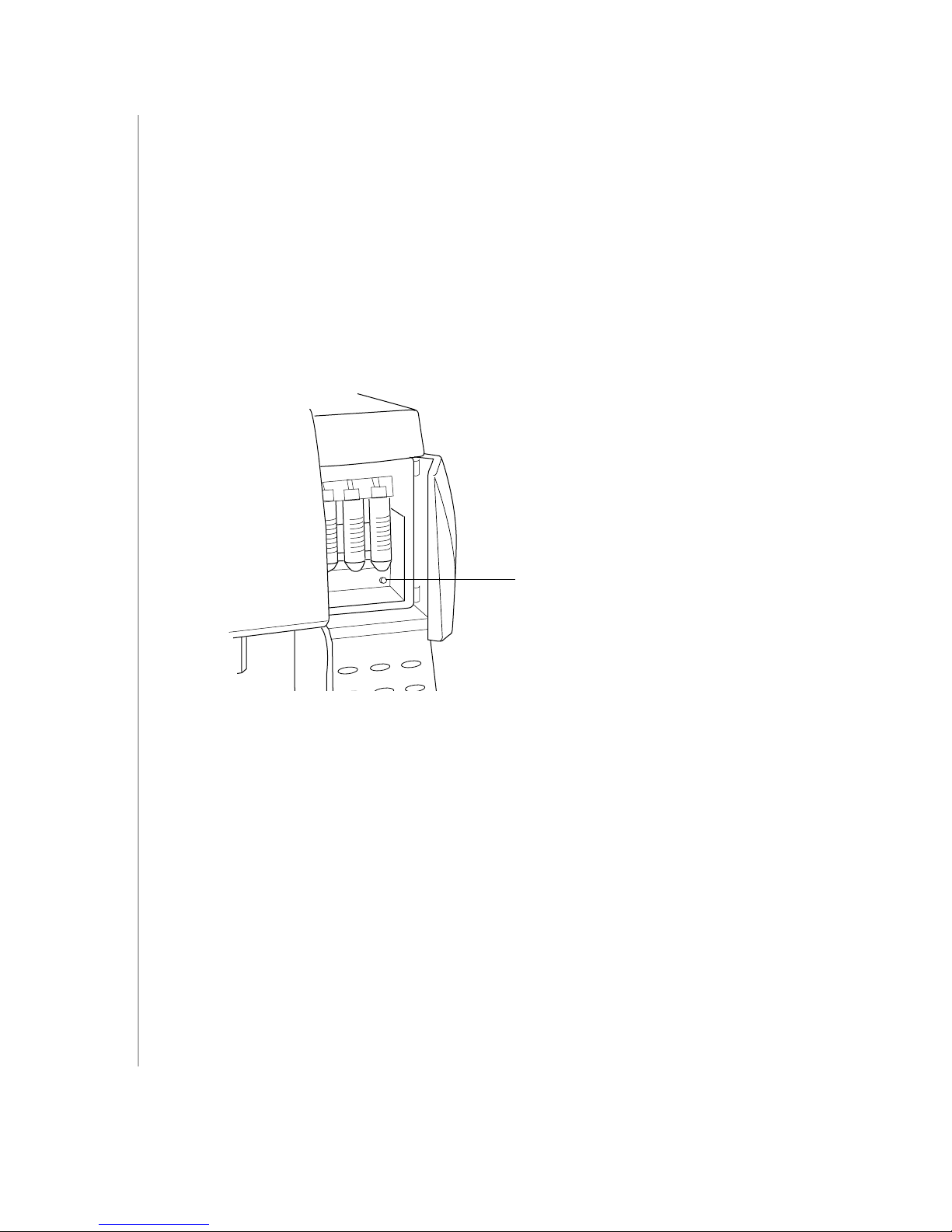
Collection Station
The area that houses the collection tubes.
purge button
Collection Tubes
The collection tubes are located in the collection station. Three 50 mL conical tubes can
be installed in the collection station. The conical tubes are used to collect the cells after
they are sorted.
Sort Line
The sort lines are tubings that deliver the sorted sample to the collection station. The
lines are not visible frm the collection station; however, periodic cleaning inolves
flushing these tubings.
Sort Line Purge Button
The purge button located in the collection station automatically rinses the sort line
when pressed.
BD FACSort System 337452 Rev. A
Page 8
8
Startup and Shutdown Procedures
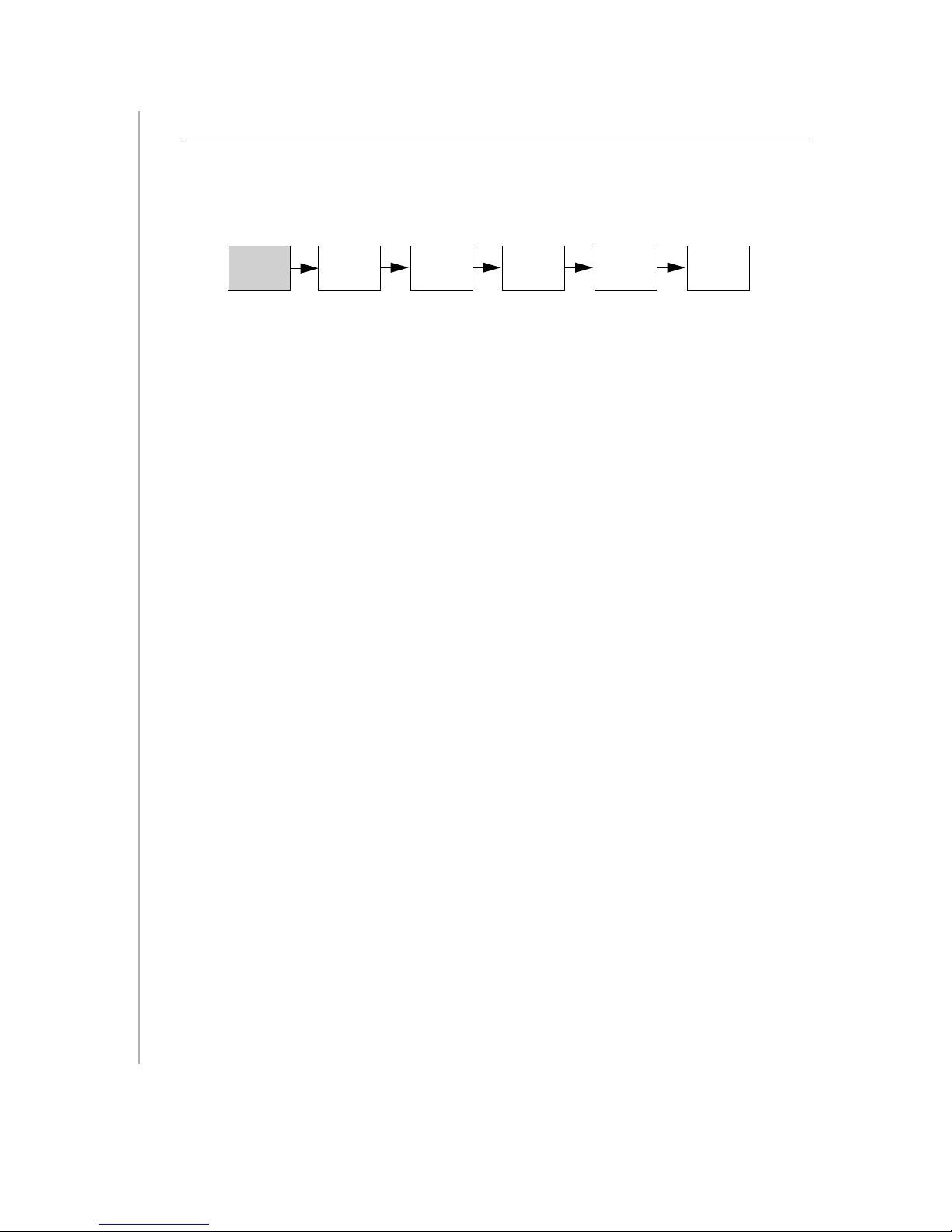
Acquisition of flow cytometry data is a multistep process. The following figure outlines
the main steps involved. In this exercise, we will focus on starting up the cytometer and
the computer.
Start Up
System
Always turn on the cytometer before turning on the computer when acquiring data.
This enables the computer to recognize that the cytometer is connected. When
analyzing data, it is not necessary to turn on the cytometer.
Turn on the cytometer.
1
The power switch is located in the upper left corner of the instrument.
2
Turn on the computer.
3
Choose your user ID and enter the password.
Perform
QC
Optimize
Settings
Acquire
Data
Analyze
Data
Shut Down
System
Filling the Sheath Tank
Recommended Sheath Fluid
• BD FACSFlow™ sheath fluid (BD Biosciences) for nonsorting applications.
• Phosphate-buffered saline (PBS) (Dulbecco’s Ca
applications.
2+
and Mg
2+
-free) for sorting
Non-recommended Sheath Fluids
• Fisher Hematology Diluent
• Isoton III
• Isolac D
• Deionized (DI) water
NOTICE If you make your own sheath fluid in the lab, be sure to pass it through a
0.22- µ m filter before running it on the instrument.
BD FACSort System 337452 Rev. A
Page 9

9
1
Slide the fluidics drawer out. Flip the vent valve toggle switch in the direction of
the arrow.
The switch, located between the sheath and waste tanks, relieves the sheath tank
of air pressure.
2
Disconnect the sheath tubing (white) and the air tubing (blue) from the
instrument by squeezing the metal clip on the quick-disconnect and pulling each
connector from the fitting.
3
Disconnect the fluid detection probe connector by squeezing the sides while
pulling the plastic connector.
4
Slide the metal bracket away from you, and lift up to remove it.
5
Remove the sheath tank, remove the fluid detection probe, and fill the tank to 3/4
its capacity with the recommended sheath fluid.
CAUTION Avoid filling the sheath tank to its maximum capacity. When a full tank
is pressurized, fluid may be forced into the air supply tubing, preventing proper
pressurization. Additionally, since there is approximately 400 mL of bleach in the
4 L waste tank, filling the sheath tank to maximum capacity will overfill the waste
tank.
6
Replace the sheath tank.
7
Replace the sheath bracket by sliding the metal bracket toward you. Make sure
that the square lip on the right side of the bracket is covering the ball valve.
8
Return the connectors to their original positions.
• Insert the sheath fluid detection probe connector into its housing.
• Insert the blue quick-disconnect into the blue-colored port until you hear a
click.
• Insert the white quick-disconnect into the white-colored port until you hear a
click.
• Verify there are no kinks in the sheath and waste tubing lines.
9
Flip the vent valve toggle switch to pressurize the tank.
Check the sheath tank to make sure it is properly pressurized. A properly
pressurized sheath tank will not be able to move around under the bracket.
BD FACSort System 337452 Rev. A
Page 10

10
Emptying the Waste Tank
Disconnect the waste tubing (orange) and the air tubing (white) from the
1
instrument by squeezing the metal clip on the quick-disconnect and pulling.
CAUTION It is good practice to empty the waste tank when you fill the sheath tank.
This prevents the waste tank from overflowing. Follow good laboratory practice:
wear appropriate safety attire and gloves when handling waste materials.
2
Disconnect the fluid detection probe connector by squeezing the sides and pulling.
3
Remove the waste tank, remove the fluid detection probe, and empty the tank
according to local, state and federal hazardous waste handling regulations.
4
Fill the waste container with 400 mL of undiluted household bleach.
This will make a 10% solution of bleach in the waste container once it is full.
Replace the waste tank.
5
Return the connectors to their original positions.
6
• Insert the waste fluid detection probe connector into its housing.
• Insert the orange quick-disconnect into the orange-colored port until you
hear a click.
• Insert the white quick-disconnect into the white-colored port until you hear a
click.
• Verify there are no kinks in the waste and air vent tubing lines.
Check the sheath filter to be sure that no air bubbles are trapped inside.
7
If bubbles are visible, gently tap the filter body to dislodge them and force them to
the top. Push the roller in the roller clamp forward to allow the pressurized
sheath fluid to force the air bubbles into the waste tank. Return the roller clamp
to closed position. Repeat steps if necessary.
Check the sheath line and the sheath filter line for bubbles.
8
If bubbles are in either line, disconnect the tubing at the quick-disconnect port
and press the tip of the valve against the side of a waste beaker. The pressurized
sheath fluid will force bubbles and sheath fluid out of the tubing.
NOTICE Allow the laser to warm up for 5 minutes after turning on the instrument,
before running samples.
BD FACSort System 337452 Rev. A
Page 11
System Shut Down
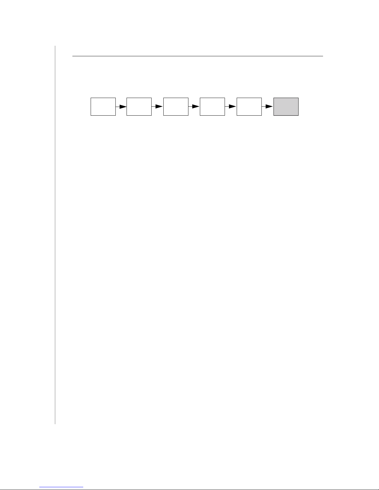
Acquisition of flow cytometry data is a multistep process. The following figure outlines
the main steps involved. In this exercise, we will focus on shutting down the cytometer
and the computer.
11
Start Up
System
Always clean the instrument before you power it off at the end of the day. Proper
cleaning will ensure that your instrument will function consistently.
To prevent the sample tube from becoming clogged and to remove adhesive dyes that
could remain in the tubing causing carryover, run a bleach solution through the SIP at
the end of each day followed by a distilled water rinse. Follow this procedure
immediately after running viscous samples or dyes such as propidium iodide (PI),
acridine orange (AO), or thiazole orange (TO).
Perform
QC
Optimize
Settings
Acquire
Data
Analyze
Data
Shut Down
System
Cleaning with 10% Bleach
1
Set the fluid control to RUN, install a tube containing 3 mL of a bleach solution
on the SIP with the support arm to the side (vacuum is on), and let it run for
1 minute.
Use BD FACS clean solution or a 1:10 dilution of bleach in DI water as the bleach
solution.
BD FACS clean solution is a bleach-based cleaning agent for daily use in
cytometer maintenance.
2
Move the support arm under the tube (vacuum is off). Allow the bleach solution
to run for 5 minutes on HI.
Rinsing with DI Water
Install a tube containing 3 mL of distilled water on the SIP with the support arm
1
to the side (vacuum is on). Let it run for 1 minute.
Move the support arm under the tube (vacuum is off). Allow the water to run for
2
5 minutes on HI.
Set the fluid control to STNDBY.
3
BD FACSort System 337452 Rev. A
Page 12

4 Place a tube containing no more than 1 mL of distilled water on the SIP.
CAUTION Sheath fluid will backflush into the tube and may cause the tube to
overfill if more than 1 mL of distilled water is in the sample tube. This could affect
instrument performance.
5 If you are finished running samples, choose Apple menu > Shutdown to turn off
the computer, and then shut off the power to the cytometer.
The tube of distilled water should remain on the SIP to prevent salt deposits from
forming in the injection tube.
Periodic Maintenance
The following periodic maintenance procedures are necessary to maintain optimal
instrument performance.
• Monthly cleaning
• Sheath filter replacement
• Air filter cleaning
• Bal seal replacement
• Sample O-ring replacement
The following section describes the monthly cleaning procedure. Other procedures can
be found in the BD FACSort User’s Guide.
Monthly Cleaning
Perform overall system fluidics cleaning at least once a month or more frequently if you
are running high volumes of samples or dyes such as propidium iodide (PI), acridine
orange (AO), or thiazole orange (TO).
1 Turn on the cytometer.
2 Remove the sheath tank.
3 Disconnect the upper tubing of the sheath filter from the SALINE FILTER port by
squeezing the metal clip on the quick-disconnect and pulling the connector from
the fitting.
4 Connect the sheath tubing (white) from the tank to the port labeled SALINE
FILTER. See Figure 3-4 on page 13.
12 BD FACSort System 337452 Rev. A
Page 13
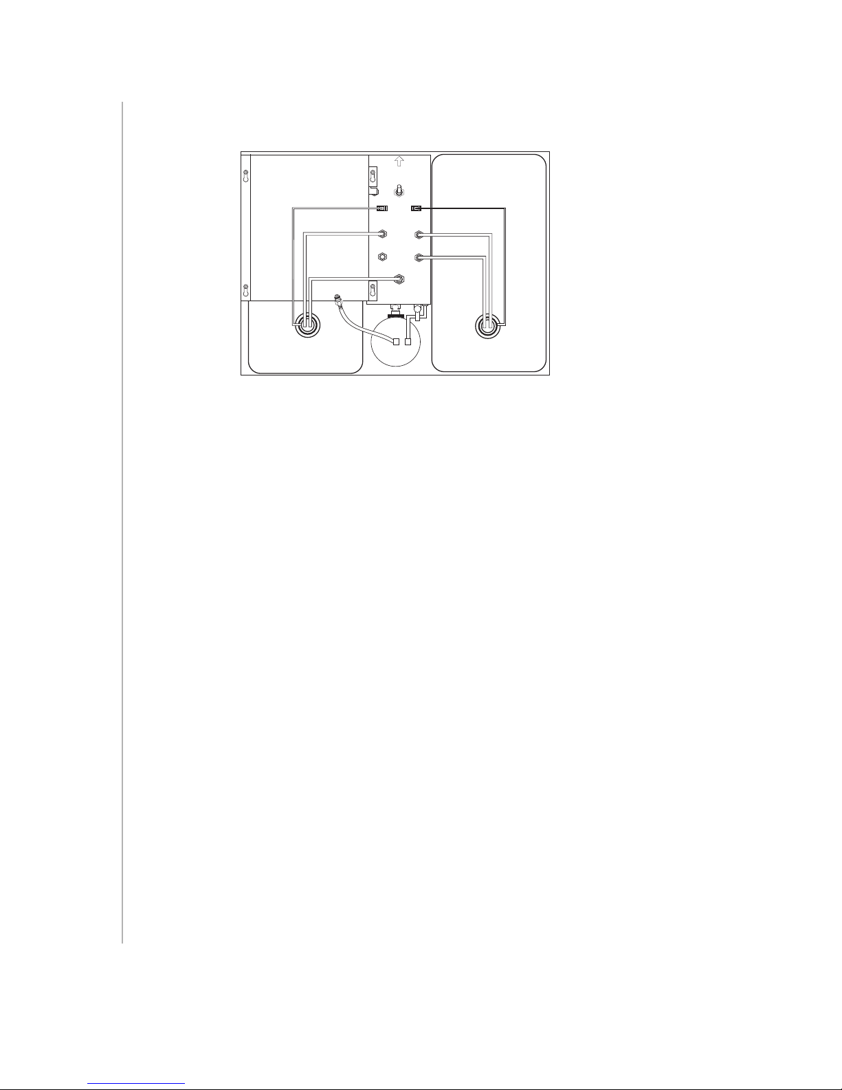
This bypasses the sheath filter and allows fluid to travel from the sheath tank
through the tubing directly to the flow cell and to the waste tank.
VENT VALVE
PRESS TO RELIEVE
PRESSURE
J69 J70
SHEATH
SALINE
FILTER
WASTE
Figure 3-4 Bypassing the sheath filter
CAUTION Running bleach or detergent through the sheath filter will break down
the filter paper within the filter body. These paper fragments might clog the flow
cell and require replacement of the filter.
5 Install a spare tank with 1 to 2 L of a bleach solution.
Use BD FACS clean solution or a 1:10 dilution of bleach in DI water as the bleach
solution.
6 Press the HI sample flow rate button, then install a tube containing 3 mL of
bleach solution on the SIP.
7 Press the RUN fluid control button and allow the solution to run for 20 to 30
minutes.
8 Remove the tube of bleach solution from the SIP.
OPTIONAL: Repeat steps 5 through 8 using BD FACS rinse solution.
BD FACS rinse solution is a detergent-based cleaning agent.
9 Repeat steps 5 through 8 using DI water.
Replace the tank containing the bleach solution with a spare tank containing 1 to
2 L of DI water. Replace the tube on the SIP with a tube containing 3 mL of DI
water.
10 Remove the tube of DI water from the SIP.
BD FACSort System 337452 Rev. A
13
Page 14

11 Replace the original sheath tank and connect the sheath filter. Place a tube
containing 1 mL of distilled water on the SIP.
12 Press the STNDBY button.
At this point, you can turn off the power to the cytometer if you are finished running
samples. The tube of distilled water should remain on the SIP to prevent salt deposits
from forming in the injection tube.
NOTICE You will need to run sheath fluid for approximately 5 minutes before
acquiring samples. If you will not be using your instrument for a week or longer,
perform monthly maintenance and keep the distilled water in the fluidic system until
you use the instrument again.
Contrad™ 70 is an excellent solution for removing clogs and wetting the fluidics. A
2% solution of Contrad 70 may be substituted for 10% bleach if necessary.
14 BD FACSort System 337452 Rev. A
 Loading...