

Page 1
N1134
INSTRUCTIONS
www.bnd.com.au
QLD Office: 17 Oasis Court
Clontarf 4019
(07) 3883 0200
NSW Office: 34-36 Marigold Street
Revesby 2212
(02) 9722 5555
VIC/TAS Office: 147-153 Canterbury Road
Kilsyth 3137
(03) 9237 7766
B&D Doors
New Zealand: 70 Allens Road
EastTamaki
114A2991
Auckland, New Zealand
(09) 273 8600
www.bnd.co.nz
SA Office: 23 Frederick Road
Royal Park 5014
(08) 8440 4747
WA Office: 96 Mulgul Road
Malaga 6090
(08) 9247 8777
The Controll-A-Door-P Diamond
has been tested and complies
with the standards:
AS/NZS 3350.2.95:2000
(incl. Amdt1) & AS/NZS
CISPR 14.1:2003
Page 2
IMPORTANT SAFETY INSTRUCTIONS FOR INSTALLATION AND USE
These safety alert symbols mean WARNING – a personal safety or property damage instruction. This
garage door opener is designed and tested to offer reasonable safe service provided it is installed,
operated, maintained and tested in strict accordance with the instructions contained in this manual.
WARNING – INCORRECT INSTALLATION
CAN LEAD TO SEVERE INJURY. FOLLOW
ALL INSTALLATION INSTRUCTIONS.
Door must not extend over public footpaths or
roads during operation.
Install only on a properly balanced garage door in
good operating condition.
must be repaired. Garage doors and components
attached to them are under extreme tension.
attempt to repair or adjust them.
garage door service.
This unit must be installed in a dry position that
is protected from the weather.
Permanently fasten the caution label adjacent to
the door control button as a reminder of safe
operating procedures.
After installation and adjustment, ensure that your
garage door
object placed on the floor.
adjust as necessary.
reverses on contact with a 40mm high
Sticking or binding doors
Do not
Get professional
Repeat monthly and
WARNING – IT IS VITAL FOR THE SAFETY
OF PERSONS TO FOLLOW ALL
INSTRUCTIONS. SAVE THESE
INSTRUCTIONS!
Watch the moving door and keep people away
until it is completely opened or closed. Do not
allow children to play with door controls. Keep
remote controls away from children.
Use caution when operating manual release if the
door is open, since it may fall rapidly if out of
balance or if springs are weak or broken. Property
damage or serious personal injury could result.
Disconnect electric power to the garage door
opener before making repairs or removing
covers.
This product is provided with a power supply cord of
special design. If damaged, it must be replaced by a
cord of the same type obtained from your local B&D
distributor, and must be fitted by a specialist.
The Protector System must be installed when the
force at the edge of the closing door force
exceeds 400N (40kg).
with the proper operation of the Safety Reverse
System or damage the garage door.
Excessive force will interfere
TABLE OF CONTENTS
Safety rules: 1
Door types: 2
Tools needed: 2
Hardware provided: 2
Before you begin: 2
Completed Installation: 2
ASSEMBLY 3-4
Assemble the rail: 3
Install the chain/belt: 3
Insert Chain/belt into rail: 3
Attach trolley to rail: 3
Fasten rail to opener and install chain/belt: 3
Attach sprocket cover: 4
Assemble header sleeve: 4
INSTALLATION
Position the header bracket: 4
Install the header bracket: 5
Attach the header bracket: 5
Position the opener: 5
Hang the opener: 6
Attach manual release rope & handle: 6
Connect electric power: 6
Install the light and lens: 6
Fasten door bracket: 7
Connect door arm to trolley: 8
114A2991
4-8
ADJUSTMENT 8-10
Program the travel limits: 8
Force adjustment: 9
Test the safety reverse system: 9
Install the door control: 10
Install the Safety Reversing Sensors (Optional): 11
Programming the code: 11
Operation of your opener: 12
Care of your opener: 12
Maintenance of your opener: 12
Problems: 13
Special features 14
Accessories: 15
Replacement parts: 16-17
Specifications: 18
Warranty: 19
1
Page 3
DOOR TYPES
A
B
C
2
1
11mm, 13mm
11/13mm
1
0mm, 8mm,
4
,5mm, 4mm
10
7
9
3
4
5
6
12
13
8
NOTICE
11
2
15
14
17
1
16
18
19
20
21
22
23
25
24
1
2
3
12
4
6
9
8
10
11
13
14
7
15
10
5
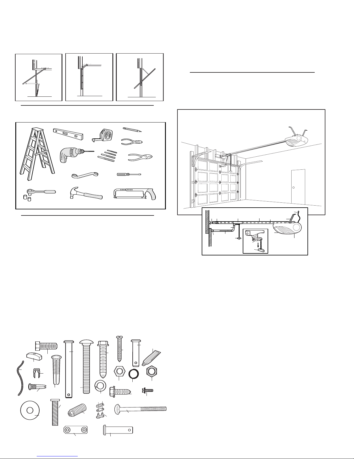
A. One-Piece Door with Horizontal Track Only
B. Sectional Door with Curved Track:
See Page 5 – Connect Door Arm to Trolley.
C. J-Style Tilt Door / One-Piece Door without Track
TOOLS NEEDED
BEFORE YOU BEGIN:
Look at the wall or ceiling above the garage door. The header
1.
bracket
must be securely fastened to structural supports.
2. Do you have a finished ceiling in your garage? If so, a support
bracket and additional fastening hardware (not supplied) may
be required.
3. Do you have an access door in addition to the garage door? If
not, Modell T7012 Emergency Access Device is required.
COMPLETED INSTALLATION
As you proceed with the assembly, installation and adjustment
procedures in this manual, you may find it helpful to refer back to
this illustration of a completed installation.
HARDWARE PROVIDED
(1) Hex Bolt (4)
(2) Clevis Pin (2)
(3) 8mm Carriage Bolt (2)
(4) Wood Screws (6)
(5) Sheet Metal Screws (2)
(6) Clevis Pin 8 x 25mm (1)
(7) Rope
(8) Handle
(9) Insulated Staples (10)
(10) Anchor (2)
(11) Concrete Anchor (6)
(12) Lock Washer (6)
(13) Hex Nut (6)
(14) Ring Fastener (4)
114A2991
(15) Rail Grease (1)
(16) Lock Nut (1)
(17) Metric Tapping Screw (2)
(18) Hex Screw (3)
(19) Flat Washer (2)
(20) Stop Bolt
(21) Spring Tensioner Nut (1)
(22) Master Link (1)
(23) Cariage Bolt, Front
Bracket (1)
(24) Transmitter Wall Mount
Bracket (1)
(25) Clevis PIn 8 x 32mm (1)
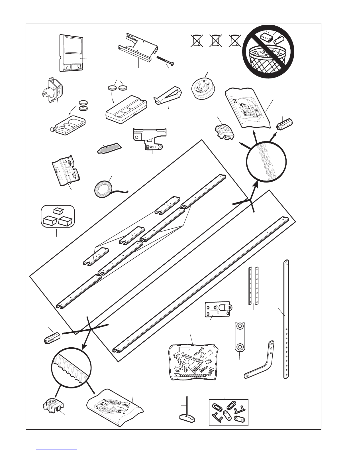
(1) Header Sleeve
(2) Idler Pulley Bracket
(3) Trolley
(4) Rail
(5) Chain/Belt
(6) Hanging Bracket
(7) Power Cord
(8) Opener
(10) Manual Release
Rope & Handle
(11) Curved Door Arm
(12) Straight Door Arm
(13) Door Bracket
and Plate
(14) Header Bracket
(15) Trolley Release Arm
(9) Light Lens
2
Page 4
ASSEMBLY SECTION
4
5
2
3
2
1
3
A
7
B
6
8
5
4
3
1
2
4
5
3
1
2
1
3
2
1
3
2
1
2
3
4
1
2
3
5
1
6
7
10
8
7
6
9
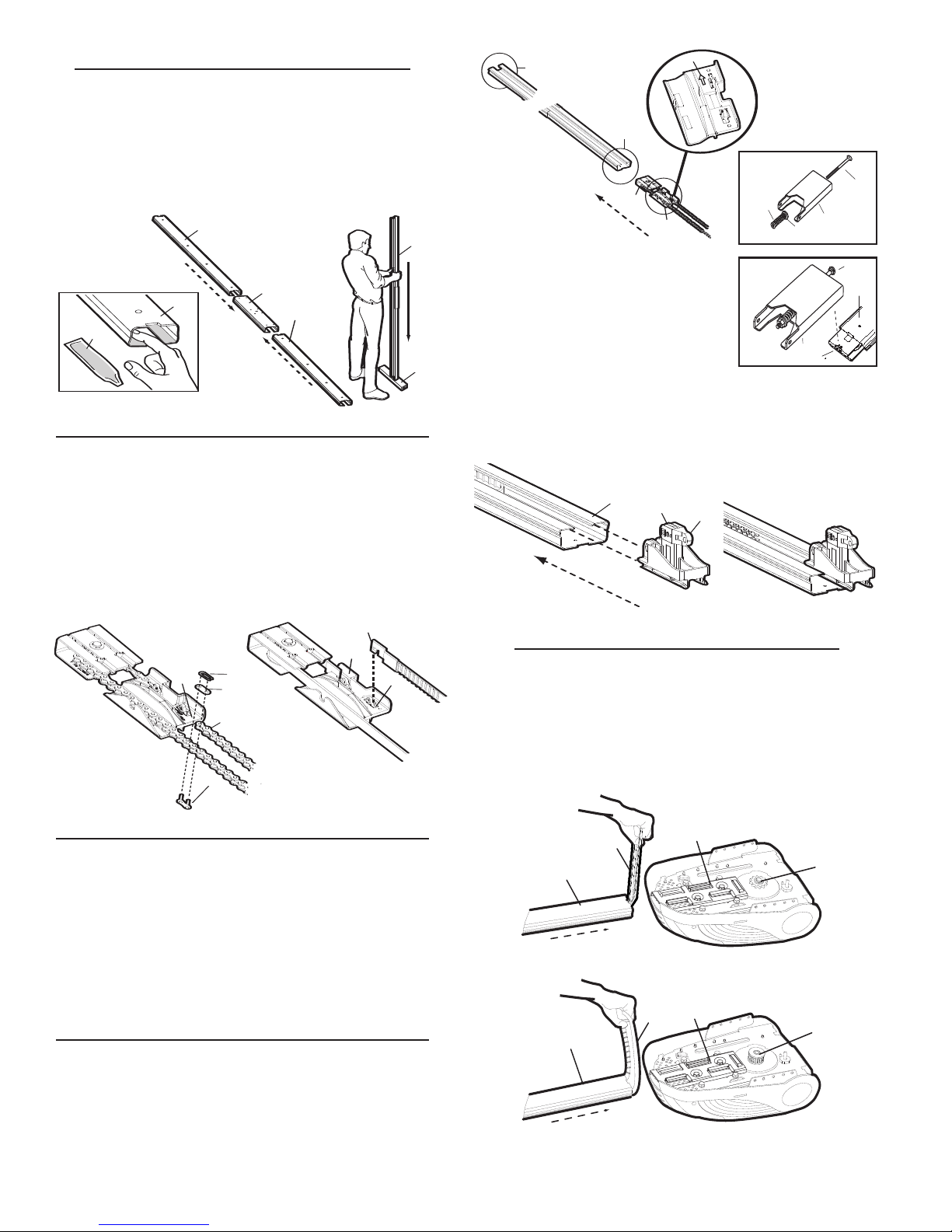
ASSEMBLE THE RAIL
Grease inside edges of rail brace sections using grease (1). Place
rail pieces (2) on flat surface for assembly. All four rail sections
are interchangeable. Slide rail brace (3) onto rail section. Connect
rail by sliding rail brace onto next rail section. Tap rail assembly
(4) on piece of wood (5) until rail sections are flush. Repeat with
remaining rail sections.
INSTALL THE CHAIN/BELT
Remove chain/belt from carton and lay chain out on floor (do not
allow chain/belt to twist).
A. Chain: Push pins of master link bar (3) through chain link (4)
and hole in back end of trolley (5). Push cap (2) over pins and
onto notches. Slide clip-on spring (1) over cap and onto pin
notches until both pins are securely locked in place.
B. Belt: Hook the trolley connector (6) into the slot (7) on the
trolley (8).
ATTACH TROLLEY TO RAIL
Slide outer trolley (1) into back (opener) end of the rail assembly
(2), be sure end with trolley release arm (3) is heading in
direction of opener. Slide outer trolley down rail until it engages
with inner trolley.
INSERT CHAIN/BELT INTO RAIL & ASSEMBLE
HEADER SLEEVE
Slide pulley bracket (1) and inner trolley (2) into back (opener
end) of rail assembly (3), be sure to insert pulley bracket as
shown with arrow (4) pointing toward front (header end) of rail (5).
Push bracket toward front (header end) of rail (5). Insert carriage
bolt (6) through header sleeve bracket (7). Loosely thread spring
nut (8) and flat washer (9) onto carriage bolt. Insert carriage bolt
(6) of header sleeve assembly (7) into bold cut out in pulley
bracket (1). Slide header sleeve assembly (7) on to front (header
end) of rail (10).
FASTEN RAIL TO OPENER AND INSTALL
CHAIN/BELT
Holding chain (4) and belt (5) out of the way, slide rail (1) onto
shim (2) until rail is secure. Take the chain/belt and wrap it
around the sprocket (3). Make sure the teeth on the sprocket
have engaged the chain/belt.
114A2991
3
Page 5
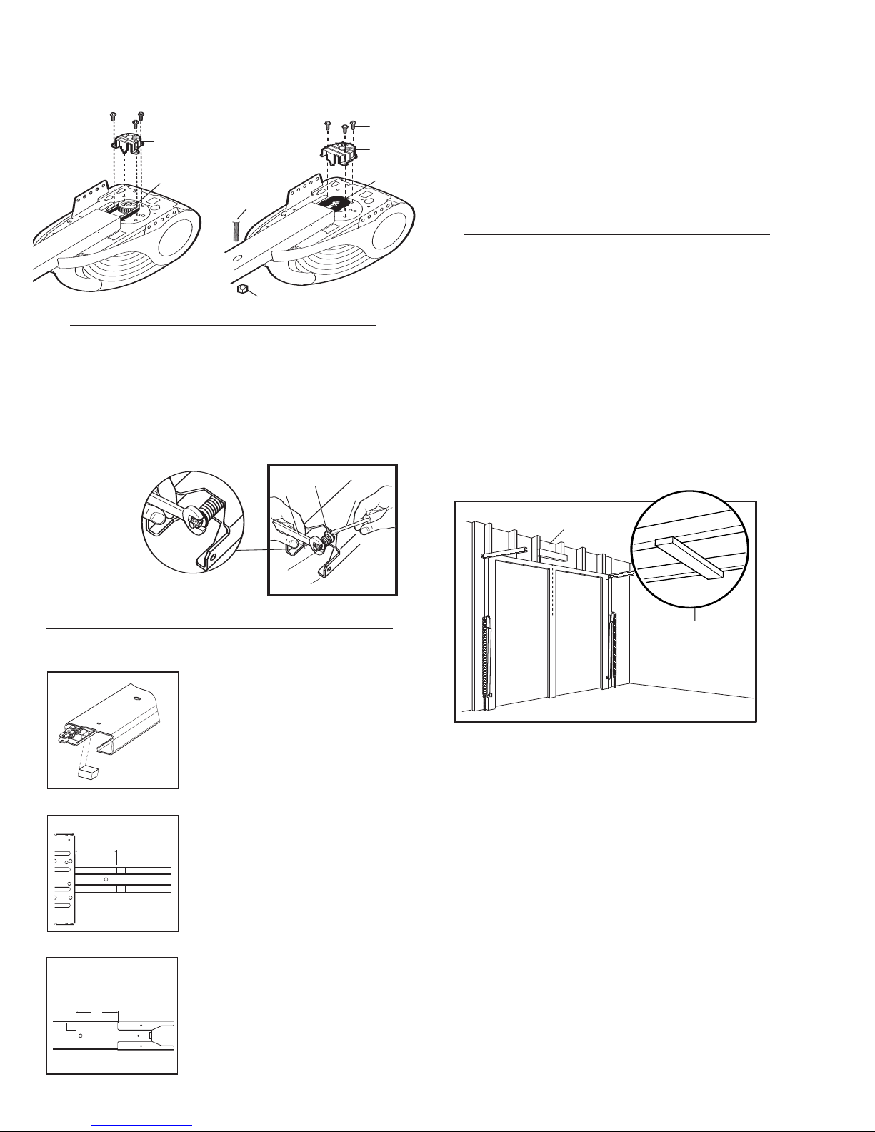
ATTACH SPROCKET COVER
2
1
3
2
1
3
4
5
1
2
3
4
5
1
2
3
114mm
114mm
Place sprocket cover (1) on top of the opener (2), secure with
screws (3). Install the trolley stop bolt (4), use the lock nut (5)
provided.
ASSEMBLE HEADER SLEEVE
Thread spring nut on carriage bolt until finger tight. Insert a
screwdriver tip (1) into one of the slots of the nut ring (2) and
brace it firmly against the header sleeve. Place an open end
wrench (3) on the square end of the spring nut (4), slightly rotate
nut about 1/4 turn clockwise until nut ring (2) is released against
header sleeve (5). This sets spring to optimum chain tension.
Chain may slip off sprocket if chain/belt is too loose. If chain does
slip re-tighten
spring nut by
turning nut
clockwise 1/2
Do NOT
turn.
overtighten
chain/belt.
INSTALLATION SECTION
Wear protective goggles when working overhead to protect
your eyes from injury.
Disengage all existing garage door locks
to avoid damage to
the garage door.
To avoid serious personal injury from entanglement, remove
all ropes connected to the garage door before installing the
operator.
It is recommended that the operator be installed
2.1m (7 feet) or more above the floor where space permits.
POSITION THE HEADER BRACKET
The header bracket must be rigidly fastened to a structural
support of the garage. Reinforce the wall or ceiling with a
40mm board if necessary. Failure to comply may result in
improper operation of safety reverse system.
You can attach the header bracket either to the header wall (1) or
to the ceiling
your particular requirements.
With the door closed, mark the vertical centreline
garage door. Extend line onto header wall above the door.
Open door to highest point of travel. Draw an intersecting
horizontal line on header wall 40mm above high point to provide
travel clearance for top edge of door.
(3). Follow the instructions which will work best for
(2) of the
CHAIN NOISE REDUCTION PADS (OPTIONAL)
1. Clean and remove grease
from rail in areas where
pads will be installed.
2. With chain tensioned, lift
up the chain and place
noise reduction pads under
the chain in orientation
shown.
3. Install with adhesive side
down allowing pad to stick
to rail.
114A2991
4
Page 6
1
2
2
1
1
2
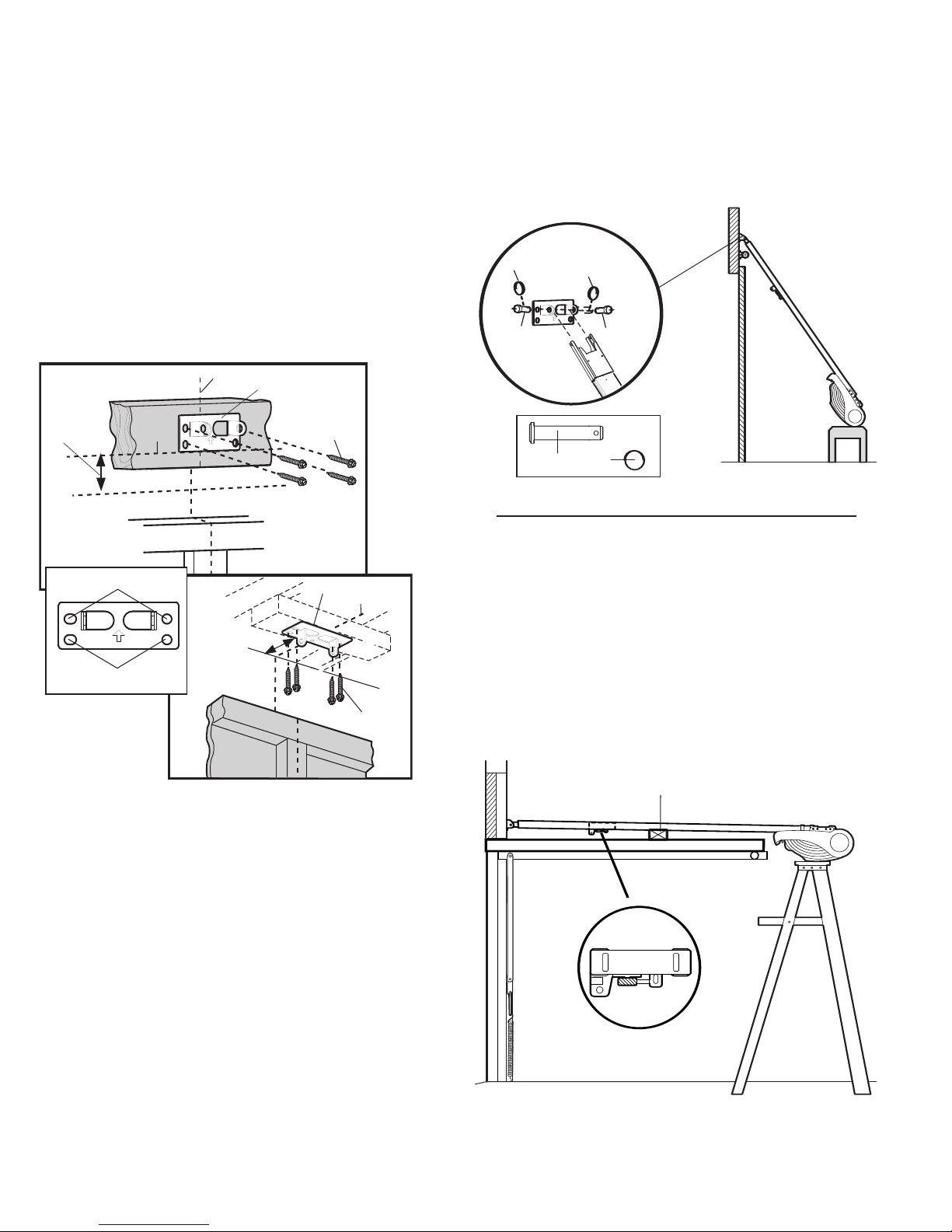
INSTALL THE HEADER BRACKET
2
50mm
(2")
3
1
4
A
B
150mm
(6")
1
2
3
5
5
1
NOTE: Refer to vertical centre and horizontal lines created in
section “Position the Header Bracket” on page 4 for proper
placement of header bracket.
A. Wall Mount: Centre the header bracket (1) on the vertical
centreline (2) with the bottom edge of the header bracket on
the horizontal line (4) (with the arrow pointing toward the
ceiling). Mark all of the header bracket holes (5). Drill 4.5mm
(3/16") pilot holes and fasten the header bracket with wood
screws (3).
B. Ceiling Mount: Extend vertical centreline (2) onto the ceiling.
Centre the header bracket (1) on the vertical mark no more
than 150mm (6") from the wall. Make sure the arrow is pointing
toward the opener. Mark all of the header bracket holes (5).
Drill 4.5mm (3/16") pilot holes and fasten the header bracket
with wood screws (3). For concrete ceiling mount, use
concrete anchors provided.
ATTACH RAIL TO HEADER BRACKET
Position opener on garage floor below the header bracket. Use
packing material to protect the cover. Raise rail until holes in the
header sleeve and holes in the header bracket align. Join with
clevis pins (1). Insert ring fasteners (2) to secure.
NOTE: To enable the rail to clear sectional door springs, it may
be necessary to lift opener onto a temporary support. The
opener must either be secured to a support or held firmly in
place by another person.
POSITION THE OPENER
SECTIONAL DOOR OR ONE-PIECE DOOR WITH TRACK
NOTE: A 25mm board (1) is convenient for setting an ideal
door-to-rail distance (unless headroom is not sufficient).
Raise the opener onto a stepladder. Open garage door. Place a
25mm board
centreline as shown. Rest the rail on the board.
If the raised door hits the trolley, pull down on the trolley release
arm to disconnect the trolley from the chain. The trolley can
remain disconnected until connecting door arm to trolley is
completed.
(1) laid flat on the top section of door near the
114A2991
5
Page 7
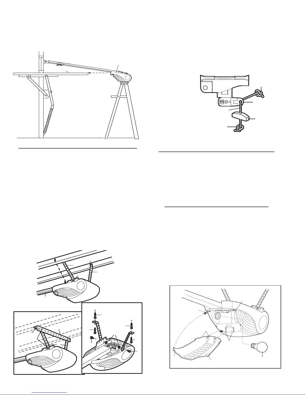
J-STYLE TILT DOOR / ONE-PIECE DOOR WITHOUT TRACK
A
2
1
1
3
B
4
2
1
3
5
4
2
3
4
2
3
3
C
2
1
2
3
4
NOTICE
2
1
4
2
4
5
5
1
3
With the door fully open and parallel to the floor, measure the
•
distance from the floor to the top of the door.
• Using a stepladder as a support, raise the top of the opener to
this height.
• The top of the door should be level with the top of the motor unit.
Do not position the opener more than 50mm above this point.
ATTACH EMERGENCY RELEASE ROPE & HANDLE
Thread one end of rope (1) through hole in top of red handle so
"NOTICE" reads right side up as shown (3). Secure with an
overhand knot (2). Knot should be at least 25mm (1") from end
of the rope to prevent slipping.
Thread other end of rope through hole in release arm of the
outer trolley (4). Adjust rope length so that handle is 1.8m
(6 feet) above the floor. Secure with an overhand knot.
NOTE: If it is necessary to cut rope, heat seal cut end with a
match or lighter to prevent fraying.
HANG THE OPENER
The opener must be securely fastened to a structural
support of the garage.
Two representative installations are shown. Yours may be
different.
provide rigid support. For concrete ceiling mount
concrete anchors
On
Hanging brackets (1) should be angled (Figure A) to
(Figure B), use
(4) provided.
each side of opener measure the distance from the opener to
the structural support (or ceiling).
Cut both pieces of the hanging bracket to required lengths.
not bend at the bracket holes.
Drill 4.5mm pilot holes in the
Do
structural supports (or ceiling). Attach ends of brackets to
supports with wood screws
(2).
Lift opener and fasten to hanging brackets with screw and lock
nut
(3). Check to make sure rail is centred over the door. Remove
25mm board. Operate door manually. If door hits the rail, raise
header bracket.
CONNECT ELECTRIC POWER
Do not attempt to operate your opener until instructed
during the travel limits programming procedure. IT WILL
NOT RUN. (See Adjustment section.)
Connect the opener to a mains which is properly EARTHED
(and as specified by local code).
Connect the door opener only to an outlet located near by the
opener.
INSTALL THE LIGHT AND LENS
Install a 40 watt maximum (240V, ESRC) light bulb in the socket
(1). Hinge the bottom of the lens (2) onto the cover from left of
the hinge bars
the upper corners and inserting the tabs
cover
(5).
To change bulb, squeeze the upper corners of the lens to
disengage tabs. The lens will drop open, remaining hinged at
bottom.
The light will turn on and remain lit for 2-1/2 minutes when
power is connected. After 2-1/2 minutes it will turn off.
(3) as shown. Close the lens by gently squeezing
(4) into slots on the
114A2991
6
Page 8
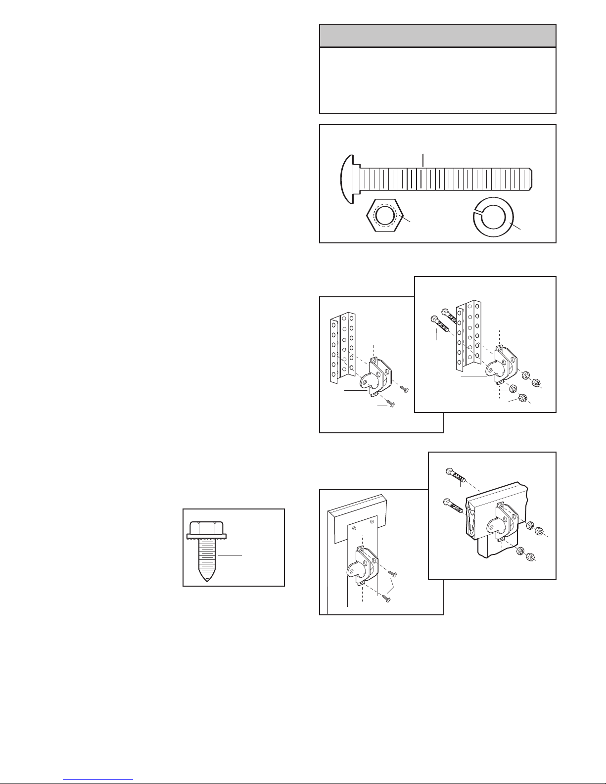
FASTEN DOOR BRACKET
6
5
4
WWARNARNINGING
CAUTIONCAUTION
1
1
5
3
4
2
2
1
5
3
4
6
2
6
Follow instructions which apply to your door type as illustrated
below or on the following page.
A horizontal reinforcement brace should be long enough to
be secured to two or three vertical supports. A vertical
reinforcement brace should cover the height of the top panel.
Figure 1 shows one piece of angle iron as the horizontal brace.
For the vertical brace, two pieces of angle iron are used to create
a U-shaped support. The best solution is to check with your
garage door manufacturer for an opener installation door
reinforcement kit.
NOTE: Many door reinforcement kits provide for direct attachment
of the clevis pin and door arm. In this case you will not need the
door bracket; proceed to Step 12.
SECTIONAL DOORS
1. Centre the door bracket on the previously marked vertical
centreline used for the header bracket installation. Note correct
UP placement, as stamped inside the bracket.
2. Position the top edge of the bracket 50mm - 100mm (2"-4")
below the top edge of the door, OR directly below any structural
support across the top of the door.
3. Mark, drill holes and install as follows, depending on your
door’s construction:
Metal or light weight doors using a vertical angle iron brace
between the door panel support and the door bracket:
• Drill 4.5mm (3/16") fastening holes. Secure the door bracket (1)
using the two 8mm x 13mm (1/4"-14x5/8") self-threading
screws (2). (Figure 2A)
• Alternately, use two 8mm (5/16") bolts (3), lock washers (4) and
nuts (5). (Figure 2B)
Metal, insulated or light weight factory reinforced doors:
• Drill 4.5mm (3/16") fastening holes. Secure the door bracket (1)
using the self-threading screws 8mm x 13mm (2). (Figure 3)
Wood Doors:
• Use top and bottom or side to side door bracket holes. Drill
8mm (5/16") holes through the door and secure bracket with
8mm x 65mm (5/16"x2") (6) carriage bolts, lock washers and
nuts. (Figure 4)
NOTE: The 8mm x 13mm (1/4"14x5/8") (2) self-threading screws are
not intended for use on wood doors.
HARDWARE
SHOWN
ACTUAL SIZE
Fibreglass, aluminum or lightweight steel garage doors
WILL REQUIRE reinforcement BEFORE installation of
door bracket. To prevent damage to garage doors
reinforce inside of door with angle iron both vertically
and horizontally.
HARDWARE SHOWN ACTUAL SIZE
Figure 1
Figure 2B
Figure 2A
114A2991
Figure 4
Figure 3
7
Page 9
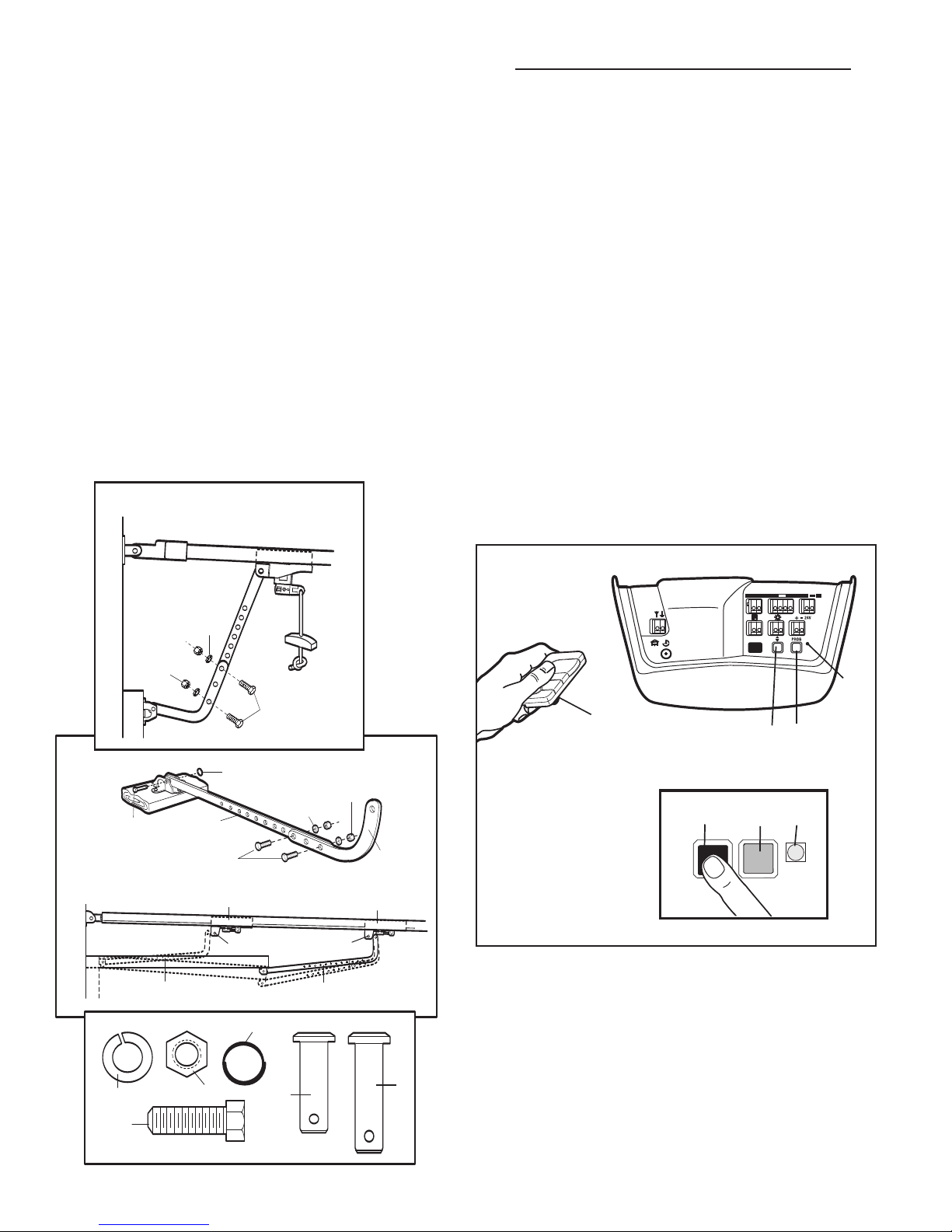
CONNECT DOOR ARM TO TROLLEY
9
12
13
10
11
8
5
4
7
1
3
8
2
4
5
3
6
4
5
7
3
8
B
A
1
2
3
2
3
1
1
3
2
60 s
120 s
180 s
O
–
4
A. Sectional Door Installation:
Close garage door and disengage the trolley as described in A.
Slide trolley about 50mm from door. Connect straight door arm
(1) to trolley door arm connector hole with a clevis pin (6).
Secure with a ring fastener
door bracket with remaining clevis pin and ring fastener. Bring
arm sections together. Line up two pairs of holes and join
sections with hardware
holes as far apart as possible.
Last, reconnect trolley as described and manually open the
door until the trolley engages.
One-Piece Door Installation:
B.
Disengage the trolley (Pull the manual release handle down
and back toward the opener).
Connect straight door arm (1) and curved door arm sections (2)
to obtain nearly the longest possible length, with hardware (3,
. With door closed, connect straight door arm section to
4, 5)
door bracket with a clevis pin
(7). Connect curved arm to trolley with remaining clevis pin.
Secure with ring fastener.
Last, reconnect trolley
manually open the door until the trolley engages.
(7). Fasten curved door arm (2) to
(3, 4, 5). For maximum rigidity, choose
(6). Secure with a ring fastener
(pull release handle straight down) and
ADJUSTMENT SECTION
SETTING THE LIMITS
Travel limits regulate the points at which the door will stop
when moving up or down. Follow the steps below to set the
limits.
To program the travel limits:
1. Press and hold the black button (1) until the yellow indicator
light (3) starts flashing slowly and then release.
2. Push and hold the black button (1) until the door reaches the
desired open position. Adjust the position of the door by using
the black (1) and orange (2) buttons. Black moves the door UP,
orange moves the door DOWN.
3. Push the programmed remote control (4) or push bar on the
door control that was shipped with your opener. This sets the
full UP (open) position. The door will travel to the floor and
reverse back to the UP (open) position. The opener has
learned its travel limits.
Check to be sure the door is high enough for your vehicle.
Adjust if necessary.
4. The indicator light (3) will stop flashing when the limits have
been learned.
NOTE: If the door reverses before it reaches the floor proceed to
#15 of the Having a Problem? section and follow the instructions
for setting the limits manually.
order to properly complete the setting of the limits.
The force MUST be learned in
114A2991
8
Page 10
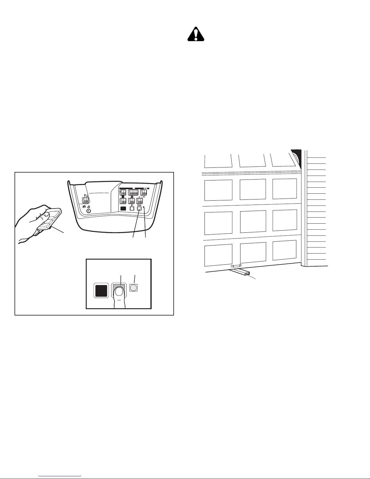
FORCE ADJUSTMENT
1
2
3
2
3
1
1
3
2
60 s
120 s
180 s
O
–
(2x)
3
2
2
3
1
3
2
60 s
120 s
180 s
O
–
4
4
1
The force, as measured on the closing edge of the door,
should not exceed 400N (40kg). If the closing force is
measured to more than 400N, a Safety Infrared Reversing
Sensor must be installed See “Install the Safety Infrared
Reversing Sensor” on page 11.
The force setting regulates the amount of power required to
open and close the door.
1. Locate the orange button (2).
2. Push the orange button (2) twice to enter unit into Force
Adjustment Mode. The LED (3) (indicator light) will flash
quickly.
3. Push the programmed remote control (4) or push bar on the
door control that was shipped with your opener. The door will
travel to the DOWN (close) position. Push the remote control
(4) again, the door will travel to the UP (open) position.
The LED (3) (indicator light) will stop flashing when the force has
been learned.
The door must travel through a complete cycle, UP and DOWN, in
order for the force to be set properly. If the unit cannot open and
close your door fully, inspect your door to ensure that it is
balanced properly and is not sticking or binding.
TEST THE SAFETY REVERSE SYSTEM
The safety reverse system test is important. Garage
door must reverse on contact with a 40mm
obstacle laid flat on the floor. Failure to properly
adjust opener may result in serious personal injury from a
closing garage door. Repeat test once a month and adjust
as needed.
Procedure: Place a 40mm obstacle (1) laid flat on the floor
under the garage door. Operate the door in the
The door must reverse on the obstruction. If the door
the obstruction, remove obstruction and repeat
Limits on page 8.
Repeat test.
When the door reverses on the 40mm obstacle, remove the
obstruction and run the opener through a complete travel cycle.
must not reverse in closed position. If it does, repeat
Door
Setting the Limits and Force on page 7 and 8 and repeat safety
reverse test.
Place 20kg at the centre of the door and ensure that the door
will not move up more than 500mm.
down direction.
stops on
Setting the
114A2991
9
Page 11
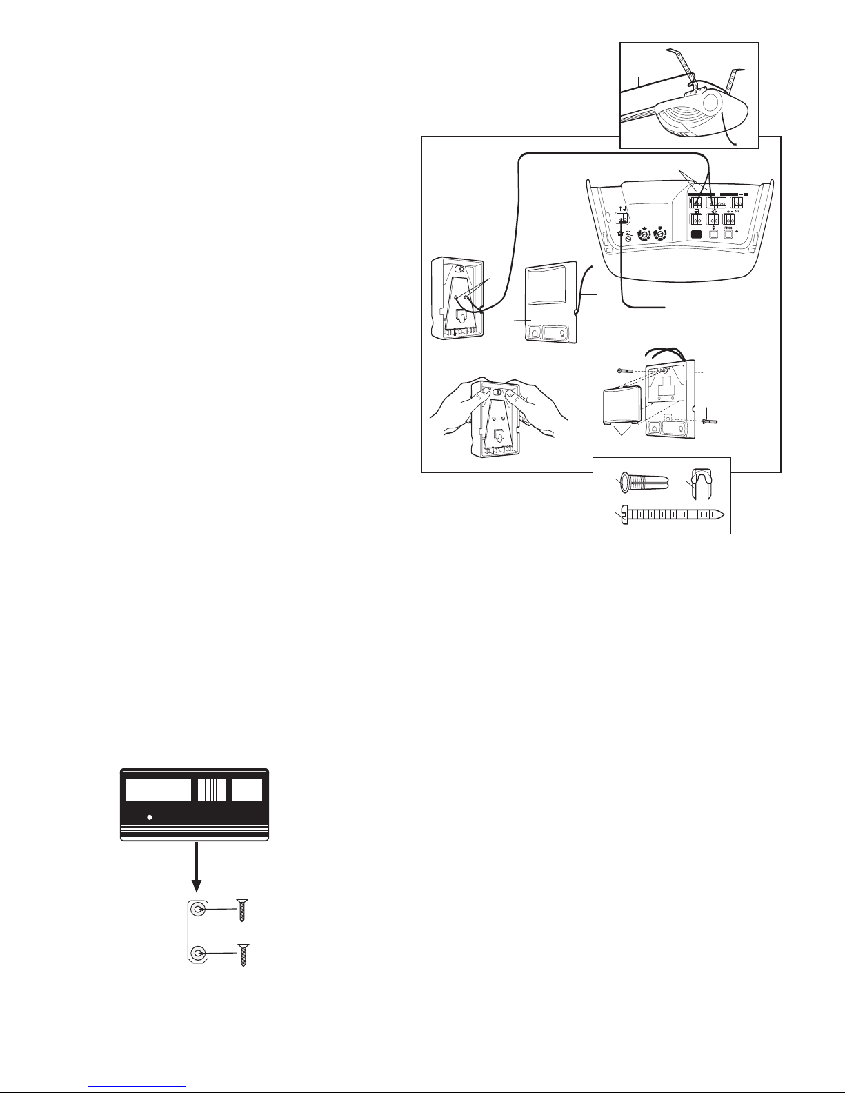
INSTALL THE DOOR CONTROL
LOCK
LIGHT
2
1
RED
WHT
8
8
kg
1
9
o
180s
120s
60s
5
7
1
3
3
2
9
5
7
1
3
kg
kg
2
1
RED
WHT
LOCK
LIGHT
1
2
7
9
4
4
3
5
6
Locate door control where the garage door is visible, away
from door and door hardware and out of the reach of
children. Mount at least 1.5m (5 feet) above the floor.
Serious personal injury from a moving garage door may
result from misuse of opener. Do not allow children to
operate the door control or remote control transmitter.
Fasten the caution label permanently to the wall near the
door control as a reminder of safe operating procedures.
There are 2 screw terminals (1) on the back of the door control
(2). Strip about 6mm (1/4") of insulation from bell wire (4).
Separate wires enough to connect the white/red wire to RED
terminal screw 1 and the white wire to WHT terminal screw 2.
Fasten the door control to an inside garage wall with sheet metal
screws (3) provided. Drill 4mm (5/32") holes and use anchors if
installing into drywall. A convenient place is beside the service
door and out of reach of children.
Run the bell wire up the wall and across the ceiling to the garage
door opener. Use insulated staples to secure wire. Connect the
bell wire to the terminals as follows: white/red to red and white to
white (5).
OPERATION OF THE MULTI-FUNCTION DOOR CONTROL
Press the white square to open or close the door. Press again to
stop the door while it is moving.
Light Feature: Press the Light button to turn the opener light on or
off. If you turn it on and then activate the opener, the light will remain
on for 2-1/2 minutes. Press again to turn it off sooner. The Light
button will not control the opener lights when the door is in motion.
Lock Feature: Prevents operation of the door from portable
remote controls. However, the door will open and close from the
Door Control push button, the Outside Keylock and the Keyless
Entry Accessories.
•
To Activate: Press and hold the Lock button for 2 seconds. The
push button light will flash as long as the Lock feature is
on.
• To turn off: Press and hold the Lock button again for 2 seconds. The
push button light will stop flashing. The Lock feature will also turn off
whenever the
PROG button on the control panel is activated.
REMOTE CONTROL WALL MOUNT (OPTIONAL)
1. Locate wall mount bracket at least 1.5m above the floor.
2. Attach to the wall with 2 x ø 3.5 max flat head screws (not
provided).
Slide remote control onto wall mount bracket.
3.
NOTE: Tightening the wall mount screws will reduce clearance
between bracket and wall.
114A2991
10
Page 12
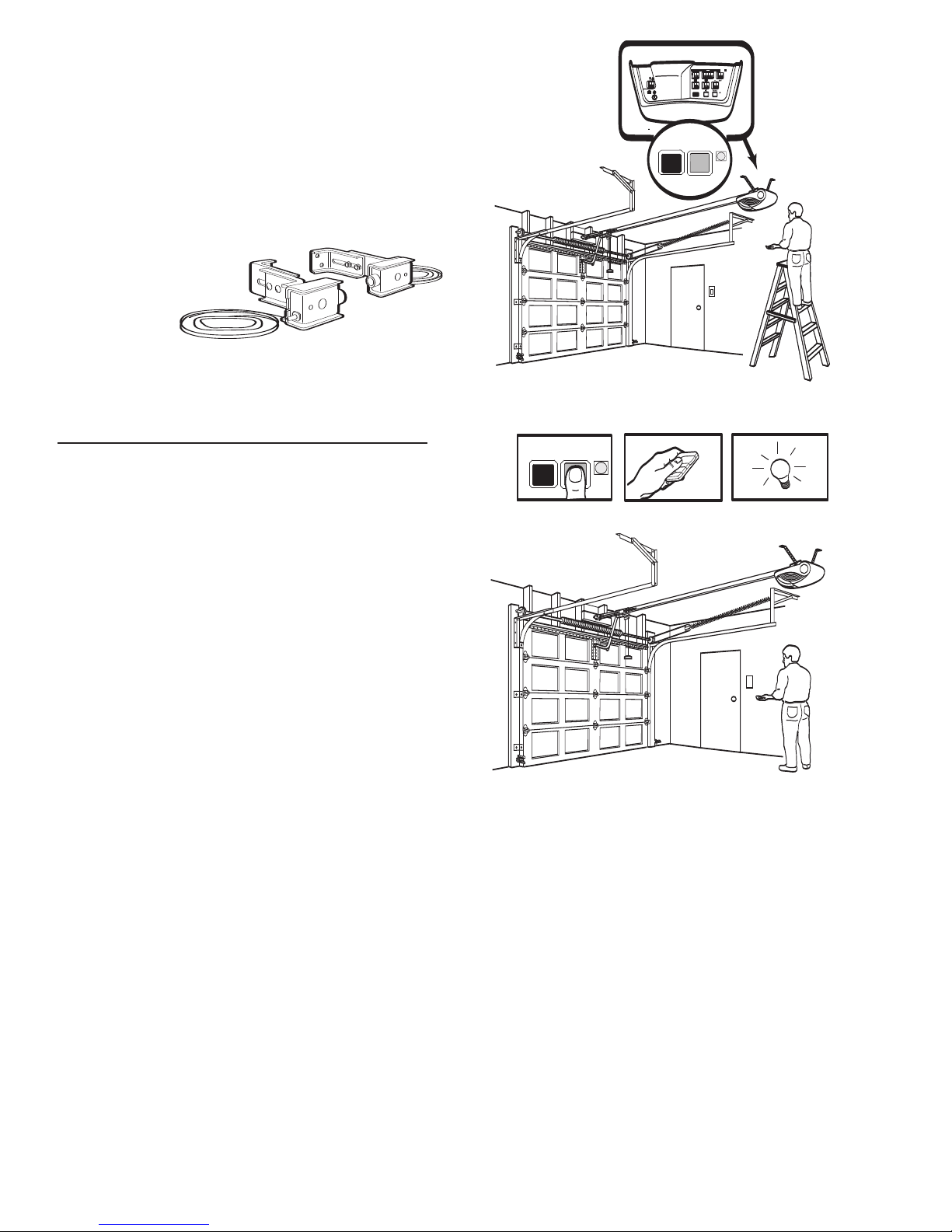
INSTALL THE SAFETY INFRARED REVERSING
1
3
2
1
3
2
60 s
120 s
180 s
O
–
SENSOR (See Accessories)
Install this accessory for all installations on doors over 2.5m
in height and when the closing force as measured on the
bottom of the door is over 400N (40kg).
After opener has been installed and adjusted, The Safety
Infrared Reversing Sensor
accessory can be installed.
Instructions are included with this accessory.
The Safety Infrared Reversing Sensor provides an additional
measure of safety against a small child being caught under a
garage door.
It uses an invisible
beam which, when
broken by an
obstruction, causes
a closing door to
open and prevents
an open door from
closing and is
strongly recommended for homeowners with young children.
Note: The opener will automatically detect the Safety Infrared
Reversing Sensor when it is installed. The opener will not close
unless the sensors are aligned and functioning.
PROGRAM YOUR OPENER AND REMOTE
Activate the opener only when door is in full view, free of
obstruction and properly adjusted. No one should enter or
leave garage while door is in motion. Do not allow children to
operate push button(s) or remote(s). Do not allow children to
play near the door.
Your garage door opener receiver and remote control transmitter
are set to a matching code. If you purchase additional remote
controls, the garage door opener must be programmed to accept
the new remote code.
Program the Receiver to Match Additional Remote Control
Codes:
Using the orange “LEARN” Button:
1. Press and release the orange “learn” button on the opener.
The learn indicator light will glow steadily for 30 seconds (1).
2. Within 30 seconds, press and hold the button on the hand-held
remote that you wish to operate your garage door (2).
Release the button when the opener light blinks. It has learned
3.
the code. If the light bulb is not installed, two clicks will be
heard (3).
Using the Multi-Function Door Control:
1. Press and hold the button on the hand-held remote that you
wish to operate your garage door (4).
2. While holding the remote button, press and hold the LIGHT
button on the Multi-Function Door Control (5).
3. Continue holding both buttons while you press the push bar on
the Multi-Function Door Control (all three buttons are held) (6).
4. Release buttons when the opener light blinks. It has learned the
code. If the light bulb is not installed, two clicks will be heard (7).
Now the opener will operate when the remote control push button
is pressed. If you release the remote control push button before
the opener light flashes, the opener has not learned the code.
To Erase all Remote Control Codes:
To deactivate any unwanted remote, first erase all codes: Press
and hold the orange “learn” button on opener until the learn
indicator light goes out (approximately 6 seconds). All previous
codes are now erased. Reprogram each remote or keyless entry
you wish to use.
3-Channel Remote:
The large button is factory programmed to operate your opener.
Additional buttons on any 3-channel remote or mini-remote can be
programmed to operate this or other B&D garage door openers.
11114A2991
Page 13
OPERATION OF YOUR OPENER
Your opener can be activated by any of the following devices:
The wall mounted door control.
•
until door starts to move.
• The Outside Keylock or Keyless Entry System (if you have
installed either of these accessories).
• The Remote Control Transmitter. Hold the push button down
until the door starts to move.
The left push button on the control panel,
•
not in a learn or limit setting mode (the indicator light must not be
on).
OPENING THE DOOR MANUALLY
Door should be fully closed if possible.
The door can be opened manually by pulling the trolley release
handle down and back (toward the opener). To reconnect the
trolley, pull the release handle straight back. It will reconnect on
the next up or down operation.
Do not use the manual release handle to pull the door open
or closed.
WHEN THE OPENER IS ACTIVATED BY THE REMOTE
CONTROL OR WALL MOUNTED DOOR CONTROL:
1. If open, the door will close. If closed, the door will open.
2. If closing, it will reverse
3. If moving, the door will stop.
4. If the door has been stopped while moving, it will next move in
the opposite direction.
5. If an obstruction is encountered while closing, the door will
reverse.
6. If an obstruction is encountered while opening, the door will stop.
7. The optional Safety Infrared Reversing Sensor uses an invisible
beam which, when broken by an obstruction, causes a closing
door to open and prevents an open door from closing. It is
STRONGLY RECOMMENDED for homeowners with young
children.
The opener light will turn on: 1) when opener is initially plugged
in; 2) when the power is interrupted; 3) when the opener is
activated.
The light turns off automatically after 2-1/2 minutes. Bulb size is
40 Watts maximum (240V, ESRC).
Hold the push button down
when the opener is
CARE OF YOUR OPENER
When properly installed, opener will provide high performance
with a minimum of maintenance. The opener does not require
additional lubrication. Lubricate springs and have your door
serviced by a professional service technician to maintain good
operating condition.
Limit and Force Adjustments: These adjustments must be
properly set and checked when the opener is installed.
conditions may cause some minor changes in the door operation,
requiring some re-adjustments, particularly during the first year of
operation.
Refer to the limit and force adjustments on page 4. Follow the
instructions carefully and
any adjustment.
Remote Control Transmitter: The lithium batteries should
produce power for up to five years. To replace batteries, use a
screwdriver blade to pry open the case along the side where
“Open” is stamped on the back. Insert batteries positive side
down. To replace cover, snap shut along both sides.
Do not dispose of old batteries with household waste. Take
batteries to a proper disposal centre.
Additional remotes can be purchased at any time for use in all
vehicles using garage. Refer to Accessories. The receiver must
be programmed to operate with any new remote.
repeat the safety reverse test after
Weather
MAINTENANCE OF YOUR OPENER
Once a Month:
Manually operate door to check for imbalance or binding.
Examine your installation, cables, springs and mountings
for wear or damage.
service if necessary. To avoid possible injury, do not use until
repaired.
• Repeat safety reverse test. Adjust if necessary.
• Check to be sure door opens and closes fully. Adjust Limits
and/or Force if necessary.
Oil door rollers, bearings and hinges. The opener does not require
additional lubrication. Do not grease the door tracks. Refer to door
manufacturer’s maintenance instructions.
Call for professional garage door
Once a Year:
114A2991
12
Page 14

HAVING A PROBLEM?
1. Opener doesn't operate from either door control or remote:
• Does the opener have electric power? Plug lamp into outlet. If it
doesn't light, check the fuse box or the circuit breaker. (Some
outlets are controlled by a wall switch.)
• Have you disengaged all door locks? Review installation
instruction warnings on page 1.
Is there a build-up of ice or snow under door? The door may be
•
frozen to ground. Remove any obstruction.
• The garage door spring may be broken. Have it replaced.
2. Opener operates from remote but not from door control:
• Is door control button lit? If not, remove the bell wire from the
opener terminals. Short the red and white terminals by touching
both terminals at the same time with a piece of wire. If the
opener runs, check for a faulty wire connection at the door
control, a short under the staples, or a broken wire.
• Are wiring connections correct? Review page 7.
3. Door operates from door control but not from remote:
• Replace battery if necessary.
If you have two or more remotes and only one operates, review
•
Program Your Opener and Remote on page 9.
• Is the door control button flashing? The opener is in lock mode.
If you have a Multi-Function Door Control, push and hold the
Lock button for 2 seconds. The door control button will stop
flashing.
4. Remote has short range:
• Is battery installed?
• Change the location of the remote control on the car.
• A metal garage door, foil-backed insulation or metal siding will
reduce the transmission range.
5. Door reverses for no apparent reason and opener light
doesn't blink:
• Is something obstructing the door? Pull manual release handle.
Operate door manually. If it is unbalanced or binding, call for
professional garage door service.
• Clear any ice or snow from garage floor area where garage
door closes.
• Repeat Setting Limits and Force, see pages 7 and 8.
Repeat safety reverse test after adjustment is complete.
6. Door reverses for no apparent reason and opener light
blinks for 5 seconds after reversing:
Check The Safety Infrared Reversing Sensor (if you have installed
this accessory). If the light is blinking, correct alignment.
7. Opener noise is disturbing in living quarters of home:
If operational noise is a problem because of proximity of the
opener to the living quarters, Vibration Isolator Kit 062155 can be
installed. This kit was designed to reduce the "sounding board
effect" and is easy to install.
8. The garage door opens and closes by itself:
Make sure remote push button is not stuck "on".
9. Door stops but doesn't close completely:
Repeat Setting the Limits, see page 7.
Repeat safety reverse test after any adjustment of door arm
length, close force or down limit.
10. Door opens but won't close:
• Check The Safety Infrared Reversing Sensor (if you have
installed this accessory). If the light is blinking, correct alignment.
• If opener light does not blink and it is a new installation, repeat
Setting the Limit and Force on pages 7 and 8.
Repeat the safety reverse test after the adjustment is complete.
11. Opener light does not turn on:
Replace light bulb (230V/40W maximum). Replace burned out
bulbs with rough service light bulbs.
12. Opener strains:
Door may be unbalanced or springs are broken. Close door and
use manual release rope and handle to disconnect trolley. Open
and close door manually. A properly balanced door will stay in any
point of travel while being supported entirely by its springs. If it
does not, call for professional garage door service to correct the
problem.
13. Opener motor hums briefly, then won't work:
• Garage door springs are broken. SEE ABOVE.
• If problem occurs on first operation of opener, door is locked.
Disable door lock.
Repeat safety reverse test after adjustment is complete.
14. Opener won't activate due to power failure:
• Pull manual release rope and handle down to disconnect trolley.
Door can be opened and closed manually. When the power is
restored, pull the manual release handle down and toward
opener. The next time the opener is activated, the trolley will
reconnect.
• The Outside Quick Release accessory (if fitted) disconnects the
trolley from outside the garage in case of power failure.
15. Setting the limits manually:
1. Press and hold the black button until the yellow indicator light
starts flashing slowly then release.
2. Adjust the position of the door by using the black and orange
buttons. Black moves the door UP (open) and orange moves
the door DOWN (close).
Check to be sure the door opens high enough for your vehicle.
3. Push the remote control or door control. This sets the UP
(open) limit and begins closing the door.
either the orange or the black button.
Adjust the desired DOWN (close) limit position using the black
and orange buttons. Check to be sure the door is fully closed
without applying excessive pressure on the rail (rail should not
bow upwards and the chain/belt should not sag or droop below
the rail). Push the remote control or door control. This sets the
DOWN (close) limit and begins opening the door.
NOTE: If neither the black or the orange button is pressed, the
door will reverse off the floor and the DOWN travel limit will be set
automatically.
Open and close the door with the remote control or door control
4.
2 or 3 times.
• If the door does not stop in the desired UP (open) position or
reverses before the door stops at the DOWN (close) position,
repeat Setting the Limits and Force on pages 7 and 8
• If the door stops in both the desired UP (open) and DOWN
(close) positions, proceed to
System.
Test the Safety Reversal
Immediately press
The door will stop.
.
114A2991
13
Page 15
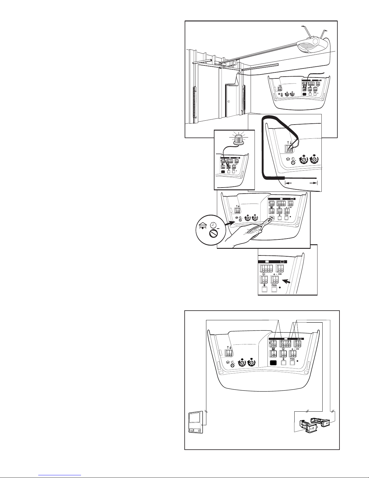
SPECIAL FEATURES
A
kg
1
9
o
180s
120s
60s
5
7
1
3
3
2
9
5
7
1
3
kg
kg
3
2
E
kg
1
9
o
180s
120s
60s
5
7
1
3
3
2
9
5
7
1
3
kg
kg
D
o
180s
120s
60s
C
250mm
kg
9
o
180s
120s
60s
5
7
1
3
9
5
7
1
3
kg
kg
1
3
2
B
kg
9
o
180s
120s
60s
5
7
1
3
9
5
7
1
3
kg
kg
1
3
2
LOCK
LIGHT
62159
62153
A. Door within a door connection
(If this feature is not installed, the jumper must remain intact.) If
installed, the door must be closed during door within a door
operation, and wiring must be correct. Remove jumper from
terminal leads. Replace with contact switch leads as shown.
B. Flashing light connection
The flashing light can be installed anywhere. Connect FLA230
light leads to terminals. When the opener is activated, the light
will begin to flash two seconds before the door moves, and
continue flashing while the door is in motion. See flashing light
instructions.
Coaxial antenna adapter
C.
A coaxial antenna connection can be used if the transmitter
range is too short. Cut off the existing antenna. Use standard
coax cable. Strip off end of insulation to 250mm. Reposition
antenna.
D. Timer for auto close
Shipped in OFF position. To activate, The Safey Infrared
Reversing Sensor, must be installed.
close door 60, 120, or 180 seconds after opening (minimum
close time is 30 seconds). If The Safety Infrared Reversing
Sensor beam is interrupted, auto close time will reset.
NOTE: Cutting the diode (as shown) places the unit into a fail-
safe mode, and your operator will function only if The Safety
Infrared Reversing Sensor is installed and properly functioning.
E. External radio feature
To supply power to an external radio receiver or accessory.
Timer can be set to
114A2991
14
Page 16
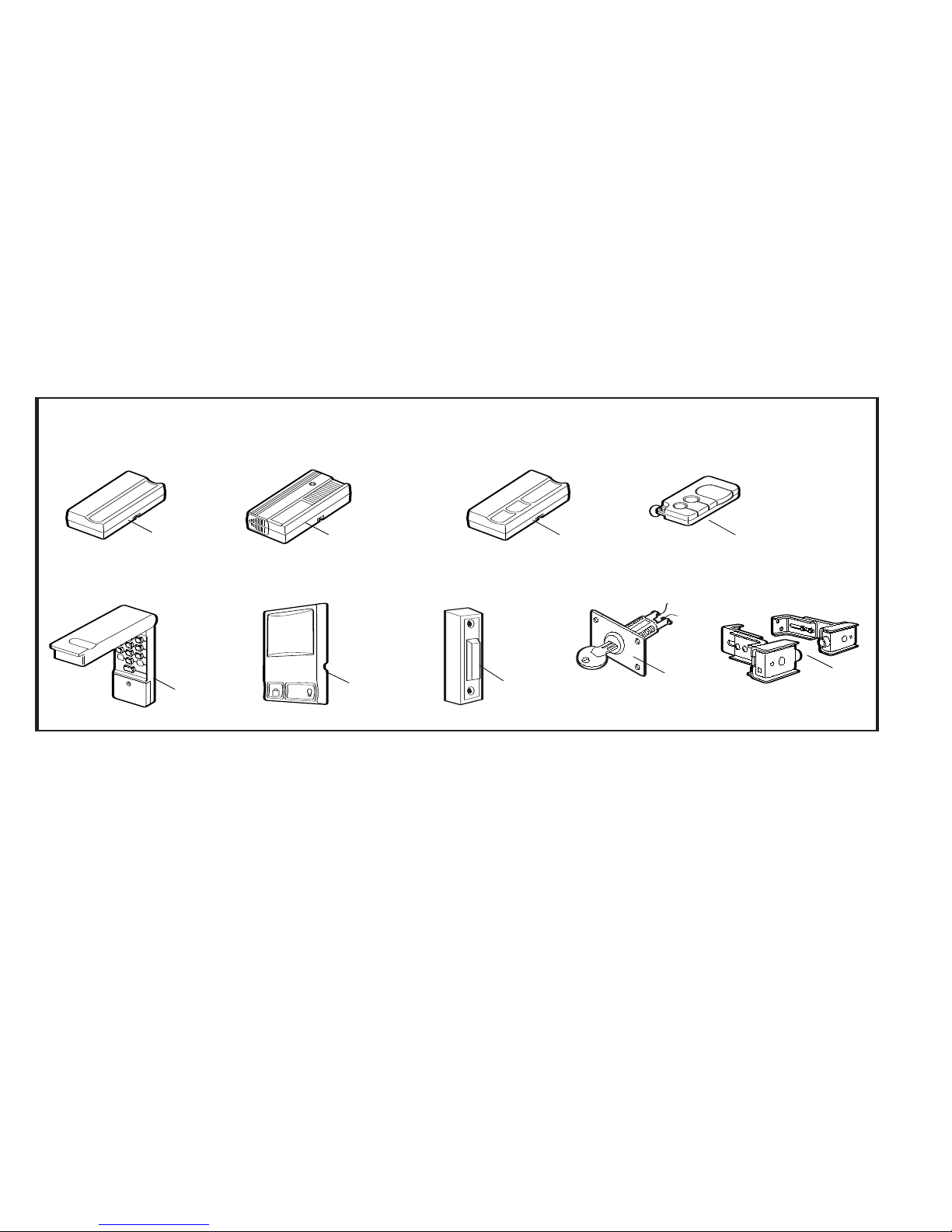
ACCESSORIES
62266
62171
62170
62162
62173
T7012
7
62228
3
4
5
LOCK
LIGHT
62159
6
2
1
8
62153
9
(1) Model 62266 1 Channel Remote
(2) Model 62171 2 Channel Remote
(3) Model
(4) Model 62162 3 Channel Keyring Remote
(5) Model 62173 Wireless Keyless Entry Keypad
(6) Model
(7) Model 62228 Push Button Wall Unit
(8) Model T7012 Emergency Key Release
(9) Model
62170 3 Channel Remote
62130 Multi-Function Door Control Panel
62153 The Safety Infrared Reversing Sensor
WIRING INSTRUCTIONS FOR ACCESSORIES
Lighted Push Button:
Outside Keylock: To opener terminals: Red-1 and White-2.
Safety Infrared
Reversing Sensor:
Door Control Panel: To opener terminals: Red-1 and White-2.
To opener terminals: Red-1 and White-2.
To opener terminals: White-2 and Black-3.
114A2991
15
Page 17
NOTI
CE
41A2828
178B34
12C778
4A1008
83A11
12VDC
Pb Cd Hg
41A5800
183D177
183D178
7423CR3
(chain)
31D525
41A5801-1 (1.7m)
41A5801 (2.3m)
41A5801-2 (2.5m)
41A5801-3 (3.0m)
41B4494-1
702
5CR
3
(ch
ain
)
41B4101-1
210C42
144C77
41A4335E (433MHz)
10A19
41A92
12C855
41A3475-24
178B35
171A28
12C810
29B137
12A0644
41A5047
10A20
LIG
HT
LOCK
41A5273-1
31D537
41A5844 (2.3m)
41A5844-1 (2.5m)
41A5844-2 (3.0m)
8423CR3
(belt)
8025CR3
(belt)
41B4103
REPLACEMENT PARTS
114A2991
16
Page 18
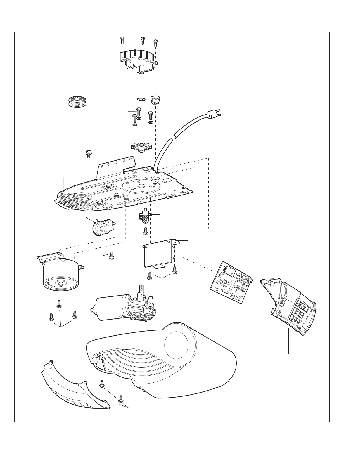
37D117-2
171A543
158A49
28A95
41B5348
108D56
171A320
41A5696-4C
41D163
41D605
171A545
171A384-8
171A384
171A315
41B5351-5
41C5392
41B4375-3
171A498
31D525
216A206
41C5350-8
171A479
26B72
41C67 (belt drive)
REPLACEMENT PARTS
114A2991
17
Page 19

SPECIFICATIONS
Input Voltage ..............230-240V, 50Hz
Max. Pull Force
Power .........................165W
Normal Torque
Stand-by power
rating @ 230V ............6W
Type ...........................DC Permanent lubrication
...........................24 V DC
Volts
Length of Travel
Travel Rate.................12-17cm per second nom., 20-100% ramp
..........................1x230V/40W/E27 socket, on when door
Lamp
Door Linkage ..............Adjustable door arm. Pull cord trolley
Personal .....................Push button and stop. Push button and
Electronic
Electrical.....................Low voltage push button wiring.
Limit Adjustment.........Electronic, Semi and Fully Automatic.
Start Circuit.................Low voltage push button circuit.
Length (Overall)..........3.2m (with standard rail)
Headroom Required ...30mm
Hanging Weight..........7.5kg
Billion Code ................32
Dip Switch .................1 (optional)
Keypad ......................1 (optional)
..........800N
...........8Nm
Motor
Drive Mechanism
.........Adjustable to 3m
starts, off 2-1/2 minutes after stop.
release.
Safety
automatic reversal in
button and automatic stop in
....................Automatic force adjustment
Dimensions
Receiver Code Registers
down direction. Push
up direction.
Operating Frequency..433.92MHz
114A2991
18
Page 20
WARRANTY
Controll-A-Door®Automatic Garage Door Opener
1.
Definitions
‘B&D’ means
(a) in Australia - B&D Doors of 17 Oasis Court Clontarf, Queensland 4019
(b) in New Zealand - B&D Doors (NZ) Ltd of 70 Allens Road East
Tamaki Auckland, which is a subsidiary of Alesco NZ Ltd.
‘Purchaser’ means the purchaser of the Opener.
‘Opener’ means the ‘Controll-A-Door Automatic Garage Door Opener’
‘Approved Distributor’ means an approved B&D distributor of the Opener.
‘Major Components’ means all components of the Opener that make up
the power head (including any track assembly, if any), that is attached to
a garage door.
‘Ancillary Components’ means all components of the Opener which are
not Major Components.
‘Manufacturer’s Written Instruction Manual’ means the instruction manual
provided with the Opener.
2. This warranty applies to every sale of an Opener to a Purchaser by B&D
or its Approved Distributor, and is the only warranty given on behalf
of B&D.
3. B&D warrants that it will, at its option, either repair or replace any
defects:
(i) in materials or workmanship in the Opener, subject to the following:
for Major Components of the Opener that are installed by B&D or
(a)
an Approved Distributor the warranty shall be valid for a period of
sixty (60) months;
for Major Components of the Opener that are not installed by B&D
(b)
or an Approved Distributor the warranty shall be valid for a period
of twelve (12) months, provided that all costs of disconnection,
reinstallation and freight shall be borne by the Purchaser.
(c) for Ancillary Components of the Opener the warranty shall be
valid for a period of twelve (12) months. Globes and batteries
excluded.
(ii) in installation for a period of twelve (12) months from the date of
installation where the Opener has been installed by B&D or its
Approved Distributor.
4. The warranties provided in clause 3(i) shall only apply to an Opener
which is being used under normal use and service in accordance with
the Manufacturer’s Written Instruction Manual and are limited to the
repair or replacement, at B&D’s option, of any defective Opener or parts
thereof.
5. The warranty provided in clause 3(i) shall apply from:
(i) the date of delivery of the Opener by B&D; or
(ii) the date of installation of the Opener by B&D or one of its Approved
Installers; or
(iii) the date of purchase of the Opener by the Purchaser; whichever is
the later.
6. (i) Where the Opener has been sold to the Purchaser by B&D, the
Purchaser shall make all warranty claims hereunder directly with B&D;
(ii) Where the Opener has been sold to the Purchaser by an Approved
Distributor, the Purchaser shall make all warranty claims hereunder
directly with the Approved Distributor.
The Purchaser will pay for any service call made by B&D or an Approved
7.
Distributor where such a call is made for the purpose of adjustment (as
described in the Manufacturers Written Instruction Manual) and not for
rectification of a defect pursuant to the warranty hereunder.
8. (i) The Purchaser shall be responsible for any expense incurred by B&D
or an Approved Distributor in ensuring that the Opener is readily
accessible for any repair work carried out under this warranty.
Where an Opener is installed outside a capital city metropolitan area
(ii)
and a warranty claim is made pursuant to this warranty, any travelling
expenses and costs of transporting the Opener, incurred
its Approved Distributor, shall be borne by the Purchaser.
9. Subject to paragraph 12 hereof;
(i) the obligations of B&D under this warranty are limited to those
contained herein and such warranties are expressly in lieu of all other
warranties, express or implied, including any implied warranty of
merchantability or fitness for a particular purpose and notwithstanding
any course of dealing between the parties or custom and usage in
the trade to the contrary.
B&D shall not be subject to nor incur and the Purchaser releases B&D
(ii)
from any claim or liability (including consequential loss or damage and
loss or use or profit) by reason of delay, defective or faulty materials or
workmanship, negligence or any act, matter or thing done, admitted or
omitted by B&D.
by B&D or
10.Subject to Clause 12 hereof, this warranty does not extend to and B&D
will be relieved of all obligations, responsibilities and liabilities (direct or
consequential) in the event that defects in manufacture of the Opener
are directly or indirectly in the opinion of B&D due to or result from:
(i) being fitted to any door or other closing device which is not of the
type or condition defined in the Manufacturers Written Instruction
Manual as suitable for installation of the Opener.
(ii) Lack of proper maintenance or care of the Door and Opener. Door
must be serviced in accordance to the door’s care and
maintenance instructions. Failure to maintain the door may result
in the opener warranty being voided.
(iii)
Incorrect and unreasonable use.
(iv) Faulty installation or adjustment of the Opener or door to which the
Opener is connected where such installation or adjustment is not
carried out by B&D or one of its Authorised B&D Distributors.
(v) Failure to observe any instructions or directions provided with the
Opener or given to the Purchaser by B&D or an Approved
Distributor.
(vi) Modifications or repairs made or attempted to be made by any
unauthorised person.
(vii) Faulty electrical wiring of structures to which the Opener is affixed.
(viii)
Radio (including citizen brand transmissions) or other electronic
interference.
(ix) Water damage, including effects from rust and corrosion.
(x) Use with doors locked.
(xi) Operation of the opener with excessively high opening or closing
force settings.
The warranty contained in Clause 3 does not cover batteries or globes
11.
and B&D shall not be liable for any defect, malfunction or failure of such
items.
12. It is expressly provided that the warranties or any terms and conditions
of them or other statement contained in this document or other literature
given to the Purchaser shall not be read or applied so as to purport to
exclude, restrict or modify or have the effect of excluding, restricting or
modifying the application in relation to the supply of the Opener of all or
any of the provisions of Divisions 2 and 2A of Part V of the Trade
Practices Act, 1974, or the Consumer Guarantees Act 1993 if the
purchase is a ‘consumer’ and purchased the opener in New Zealand,
(“The Act”) as amended or the exercise of a right conferred by such a
provision or any other condition or warranty implied by any relevant
State Act or Territorial Ordinance or by the general law and which by
law cannot be excluded, restricted or modified provided that to the
extent that the Act permits B&D to limit its liability for a breach of
condition or warranty implied by the Act, B&D’s liability for such breach
shall be limited to the payment of the cost of replacing the Opener or
acquiring an equivalent Opener or repairing the Opener.
13. This warranty shall be governed by and construed in accordance with
Australian law if the opener was purchased in Australia, or New Zealand
law if the opener was purchased in New Zealand.
14. Upon making a claim under this warranty the purchaser must produce
proof of the date of purchase, together with the warranty certificate set
out below:
Purchased from:
Installed by:
Installed on (date):
The Purchaser shall complete this certificate and keep it together with a
copy of the receipt of purchase in a safe place – production of such
information will assist the handling of a claim made under this warranty.
The B&D Diamond and Controll-A-Door are registered Trademarks of
B&D Australia Pty Ltd., an Alesco company. ABN 25010473971.
114A2991 ©2005, All Rights Reserved Printed in Mexico
 Loading...